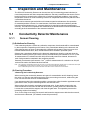
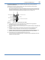
1
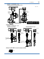
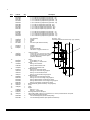
User’s Manual CONDUCTIVITY METERING SYSTEM Model SC210G CONDUCTIVITY DETECTOR IM 12D08G03-01E R IM 12D08G03-01E 8th Edition i < Introduction > Introduction Conductivity Measuring System consists of a SC210G Conductivity Detector, as described in this manual, used in conjunction with an SC202, FLXA202/FLXA21 or SC450G Conductivity Converter. The SC210G Conductivity Detector may use sensors with cell constant of 0.05 cm-1, to measure conductivities of 0 to 200 µS/cm, or sensors with cell constant of 5 cm-1, to measure conductivities of 0 µS/cm to 20 mS/cm. The SC210G detector may be inserted into the process piping, for direct measurement of process liquids, or a sample of the liquid may be obtained via a piping connection. Users should thoroughly read this manual prior to using the product, so as to understand how to obtain best results when using it. This user manual is intended to cover installation, piping and wiring, periodic inspection and maintenance for the SC210G Conductivity Detector. This manual does not describe the units in Table shown below which are the component units of the conductivity measuring system. Each of these units comes with an instruction manual, so read the applicable manuals for details of the units concerned. Manual Name IM No. FLXA202, FLXA21 2-Wire Liquid Analyzer IM 12A01A02-01E SC202G, SC202SJ 2-Wire Conductivity Transmitter IM 12D08B02-01E SC402G 4-Wire Conductivity Converter IM 12D08N04-01E SC450G 4-Wire Conductivity Converter IM 12D08N05-01E When you receive the SC210G detector, carefully unpack it and inspect for evidence of any damage that may have occurred during transit. The SC210G is shipped with the specifications and options specified at order time. Confirm that the model and suffix codes on the nameplate agree with those specified in your order. For more details of model and suffix codes, refer to Section 1.2.2 later in this manual. Media No. IM 12D08G03-01E 8th Edition : Oct. 2015 (YK) All Rights Reserved Copyright © 2007, Yokogawa Electric Corporation IM 12D08G03-01E 8th Edition : Oct.28,2015-00 ii < Introduction > For the safe use of this equipment n Safety, Protection, and Modification of the Product • In order to protect the system controlled by the product and the product itself and ensure safe operation, observe the safety precautions described in this user’s manual. We assume no liability for safety if users fail to observe these instructions when operating the product. • If this instrument is used in a manner not specified in this user’s manual, the protection provided by this instrument may be impaired. • Be sure to use the spare parts approved by Yokogawa Electric Corporation (hereafter simply referred to as YOKOGAWA) when replacing parts or consumables. • Modification of the product is strictly prohibited. • The following symbols are used in the product and user’s manual to indicate that there are precautions for safety: n Notes on Handling User’s Manuals • Please hand over the user’s manuals to your end users so that they can keep the user’s manuals on hand for convenient reference. • Please read the information thoroughly before using the product. • The purpose of these user’s manuals is not to warrant that the product is well suited to any particular purpose but rather to describe the functional details of the product. • No part of the user’s manuals may be transferred or reproduced without prior written consent from YOKOGAWA. • YOKOGAWA reserves the right to make improvements in the user’s manuals and product at any time, without notice or obligation. • If you have any questions, or you find mistakes or omissions in the user’s manuals, please contact our sales representative or your local distributor. n Warning and Disclaimer The product is provided on an “as is” basis. YOKOGAWA shall have neither liability nor responsibility to any person or entity with respect to any direct or indirect loss or damage arising from using the product or any defect of the product that YOKOGAWA can not predict in advance. n Compliance with the simple apparatus requirements SC210G meet the simple apparatus requirements defined in the following standards. Note: TIIS certified types cannot be connected. Use the sensors under the conditions of use required by the standards. Applicable standards: ANSI/ISA-60079-11 (2014) ANSI/ISA-60079-0 (2009) CAN/CSA-C22.2 NO. 60079-11:14 CAN/CSA-C22.2 NO. 60079-0:11 방호장치 의무안전인증 고시 GB 3836.4-2010 IM 12D08G03-01E 8th Edition : Oct.28,2015-00 iii < Introduction > Conditions of use: (1) Use in combination with an internally isolated transmitter, or use with, a transmitter in combination with isolated barrier. The FLXA21 is internally isolated. (2) Upper limit of the process temperature. The upper limit of process temperature is indicated below when the sensor is used in combination with a YOKOGAWA transmitter. For FLXA21, model and suffix code below is available. FLXA21-D-□-D-EA-C1-○-A-N-LA-N-NN □: can be any value. ○: must be NN or C1. Any option code is available. For SC202S, model and suffix code below is available SC202S-A-E There are no SC202S models that meet the Korean explosion proof standards. Any option code is available. Upper limit of process temperature on the SC210G Transmitter used in combination Ambient temperature Ta Temperature class *1: FLXA21 40°C SC202S 60°C 40°C 60°C T6 30 30 64 64 T5 95 (*1) 35 95 (*1) 79 T4 105 45 105 105 T3 105 65 105 105 T2 105 105 105 105 T1 105 105 105 105 Care about upper limit 100°C of temperature class T5 should be taken. Other warnings are provided in the following. WARNING Handling precautions: (1) Potential electrostatic charging hazard Electrostatic charge may cause an explosion hazard. Avoid any actions that cause the generation of electrostatic charge, e.g., rubbing with a dry cloth. (2) Because the enclosure of terminal box is made of aluminium, ignition sources due to impact and friction sparks are excluded. (3) IEC60079-14 (Electrical installations in hazardous areas) requires a label indicating ‘simple apparatus’, stick this label to this sensor if necessary. IM 12D08G03-01E 8th Edition : Oct.28,2015-00 iv < Introduction > n Symbol Marks Throughout this user’s manual, you will find several different types of symbols are used to identify different sections of text. This section describes these icons. WARNING Indicates a potentially hazardous situation which, if not avoided, could result in death or serious injury. CAUTION Indicates a potentially hazardous situation which, if not avoided, may result in minor or moderate injury. It may also be used to alert against unsafe practices. IMPORTANT Indicates that operating the hardware or software in this manner may damage it or lead to system failure. NOTE Draws attention to information essential for understanding the operation and features. IM 12D08G03-01E 8th Edition : Oct.28,2015-00 v < Introduction > After-sales Warranty n Do not modify the product. n During the warranty period, for repair under warranty consult the local sales representative or service office. Yokogawa will replace or repair any damaged parts. Before consulting for repair under warranty, provide us with the model name and serial number and a description of the problem. Any diagrams or data explaining the problem would also be appreciated. l If we replace the product with a new one, we won’t provide you with a repair report. l Yokogawa warrants the product for the period stated in the pre-purchase quotation Yokogawa shall conduct defined warranty service based on its standard. When the customer site is located outside of the service area, a fee for dispatching the maintenance engineer will be charged to the customer. n In the following cases, customer will be charged repair fee regardless of warranty period. • Failure of components which are out of scope of warranty stated in instruction manual. • Failure caused by usage of software, hardware or auxiliary equipment, which Yokogawa Electric did not supply. • Failure due to improper or insufficient maintenance by user. • Failure due to modification, misuse or outside-of-specifications operation which Yokogawa does not authorize. • Failure due to power supply (voltage, frequency) being outside specifications or abnormal. • Failure caused by any usage out of scope of recommended usage. • Any damage from fire, earthquake, storms and floods, lightning, disturbances, riots, warfare, radiation and other natural changes. n Yokogawa does not warrant conformance with the specific application at the user site. Yokogawa will not bear direct/indirect responsibility for damage due to a specific application. n Yokogawa Electric will not bear responsibility when the user configures the product into systems or resells the product. n Maintenance service and supplying repair parts will be covered for five years after the production ends. For repair for this product, please contact the nearest sales office described in this instruction manual. IM 12D08G03-01E 8th Edition : Oct.28,2015-00 Blank Page < CONTENTS > vii CONDUCTIVITY METERING SYSTEM Model SC210G CONDUCTIVITY DETECTOR IM 12D08G03-01E 8th Edition CONTENTS Introduction.....................................................................................................i For the safe use of this equipment..............................................................ii After-sales Warranty.....................................................................................v 1.General....................................................................................................... 1-1 1.1 SC210G Conductivity Detector........................................................................ 1-1 1.1.1 1.2 2. Specifications..................................................................................................... 1-2 1.2.1 Standard Specifications...................................................................... 1-2 1.2.2 Model and Suffix Codes...................................................................... 1-3 1.2.3 External Dimensions........................................................................... 1-5 Name and Function of Each Part............................................................. 2-1 2.1 3. Conductivity Detector.......................................................................... 1-1 Conductivity Detector....................................................................................... 2-1 Installation and Piping, Wiring................................................................. 3-1 3.1Installation.......................................................................................................... 3-1 3.1.1 Site Selection...................................................................................... 3-1 3.1.2Preparation......................................................................................... 3-1 3.1.3 Installation of the Detector.................................................................. 3-4 3.2Piping.................................................................................................................. 3-5 3.2.1 Joint Position....................................................................................... 3-5 3.2.2 Material for Piping............................................................................... 3-5 3.2.3 Notes for Piping................................................................................... 3-6 3.3Wiring.................................................................................................................. 3-7 3.3.1 Detector Cable Specifications............................................................ 3-7 3.3.2 Laying Detector Cables...................................................................... 3-8 4.Operation.................................................................................................... 4-1 4.1 4.2 Preparation for Operation................................................................................. 4-1 4.1.1 Checking Piping and Wiring................................................................ 4-1 4.1.2 Flowing Measured Solution................................................................ 4-1 4.1.3 Checking Operation............................................................................ 4-1 Steady-State Operation..................................................................................... 4-2 4.2.1 If any Problem Arises During Operation............................................. 4-2 4.2.2 Cautions When Stopping or Resuming Operation............................. 4-2 IM 12D08G03-01E 8th Edition : Oct.28,2015-00 5. < CONTENTS > viii Inspection and Maintenance.................................................................... 5-1 5.1 Conductivity Detector Maintenance................................................................ 5-1 5.1.1 Sensor Cleaning................................................................................. 5-1 5.1.2 Replacing the Sealing O-ring.............................................................. 5-2 5.1.3 Replacement of a Faulty Electrode.................................................... 5-4 Customer Maintenance Parts List.......................................CMPL 12D08F00-01E Revision Information................................................................................................i IM 12D08G03-01E 8th Edition : Oct.28,2015-00 < 1. General > 1-1 1.General 1.1 SC210G Conductivity Detector 1.1.1 Conductivity Detector The conductivity detector can be classified into the following two types in terms of application and cell constant. SC210G-A conductivity detector for low range (cell constant: 0.05 cm-1) SC210G-B conductivity detector for medium range (cell constant: 5 cm-1) These conductivity detectors are structured (follow-through structure) to introduce a measuring solution to themselves through a connected sampling pipe (nominal diameter: 15A). The SC210G-A and SC210G-B have a type which is connected directly to a process pipe (direct insertion type). (1) SC210G-A conductivity detector for low range (cell constant: 0.05 cm-1) This detector's electrode is a stainless steel (316 SS) 2-eledtrode coaxial type and is used to measure a solution whose conductivity is 0 to 200 µS/cm. (2) SC210G-A conductivity detector for medium range (cell constant: 5 cm-1) This detector's electrode is a 2-electrode type having three ringed platinum electrodes arranged at an equal distance in its glass tube bore (of the three platinum electrodes, two on the sides are short-circuited internally and serve as a pair with the middle electrode). It is used to measure a solution whose conductivity is 200 µS/cm to 20 mS/cm. SC210G-A cell constant: 0.05 cm-1 Figure 1.1 SC210G-B cell constant: 5 cm-1 Electrode Construction of the Conductivity Detectors IM 12D08G03-01E 8th Edition : Oct.28,2015-00 1.2 1-2 < 1. General > Specifications This chapter describes the specifications of the SC210G Conductivity Detector. For the specifications of other devices (for example, the SC202G, SC202SJ, FLXA202/FLXA21 two-wire conductivity transmitter, the PH201G distributor), refer to their respective user’s manuals. 1.2.1 Standard Specifications Cable with pin terminals (applicable to FLXA202/FLXA21, SC202G and SC202SJ) Cable with M4 ring terminals (applicable to FLXA202/FLXA21) Cable with M3 ring terminals (applicable to SC450G, SC202/TB) Object of measurement : Conductivity of solutions Measuring principle : Two-electrode system Cell constant : 0.05 cm-1, 5 cm-1 Measuring range : 0 - 0.5 µS/cm to 0 - 200 µS/cm (Cell constant: 0.05 cm-1) 0 - 200 µS/cm to 0 - 20 mS/cm (Cell constant: 5 cm-1) Temperature Range : 0 to 105 °C (chamber material: SCS14) 0 to 100 °C (chamber material: Polypropylene) Pressure range : 0 to 1 MPa (chamber material: SCS14) 0 to 500 kPa (chamber material: Polypropylene) Measured solution condition : Although flow rate is not limited in measurement, less than 20 L/min is recommended for flow-through type. If slurry is included in measured solutions in flow-through type detectors, the electrode part and the inside of solution chamber may be worn significantly. Air bubbles should not be mixed in the measured solutions to obtain correct measured values. Temperature sensor : Thermistor (PB36NTC) Wet part Materials SC210G-A : For sensor, Stainless steel (316 SS), Fluoro rubber (FKM) (O-ring) and Polytrifluorochloroethylene For body, Stainless steel (316 SS), polypropylene and Fluoro rubber (FKM) (O-ring) SC210G-B : For sensor, Platinum, glass and Fluoro rubber (FKM) (O-ring) For body, Stainless steel (316 SS), polypropylene and Fluoro rubber (FKM) (O-ring) Construction : JIS C0920 watertight (equal to NEMA4) Applicable transmitter/converter with various detectors Detector Type of terminals Converter: SC100 (*3) Transmitter: SC202G, SC202SJ (*3) Converter: SC402G (*3) Converter: SC450G Analyzer: FLXA202/FLXA21 *1: *2: *3: Pin Yes Yes (*2) Yes SC210G Ring M4 Ring M3 N.A. N.A. Yes (*1) N.A. N.A. Yes N.A. Yes N.A. Applicable when option code /TB (screw terminal) specified for SC202G/SC202SJ. Both pin and M3 ring can be used for SC450G, but M3 ring are recommended. SC402G, SC100 and SC202SJ have been terminated. IM 12D08G03-01E 8th Edition : Oct.28,2015-00 < 1. General > 1.2.2 1-3 Model and Suffix Codes (1)SC210G Conductivity Detector Construction Model Suffix Code SC210G ............................... Measuring -A range -B Screw-in type -100 -103 -206 Flange type -207 -208 Flow-through -302 -312 type (*1) -303 -313 -304 -314 -305 -315 -306 -402 With gate -403 valve Sensor length -L015 -L030 -L050 -L100 -L150 -L200 Cable length -03 -05 -10 -15 -20 -AA -BB -CC -DD -EE -Y1 -Y2 -Y3 -Y4 -Y5 Style code *A Option Option Code Description ...................... ...................... ...................... ...................... ...................... ...................... ...................... ...................... ...................... ...................... ...................... ...................... ...................... ...................... ...................... ...................... ...................... ...................... ...................... ...................... ...................... ...................... ...................... ...................... ...................... ...................... ...................... ...................... ...................... ...................... ...................... ...................... ...................... ...................... ...................... ...................... ...................... ...................... ...................... /SCT /ANSI /PF /PS /SS /X1 /DG1 Medium range; cell constant: 5 cm-1 R1-1/2 1-1/2NPT male JIS 10K 50 RF flange ANSI Class150 2 RF flange (with serration) JPI Class150 2 RF flange Rc1/2 female, chamber material: SCS14 Rc1/2 female, chamber material: PP 1/2NPT female, chamber material: SCS14 1/2NPT female, chamber material: PP JIS 10K 15 RF flange, chamber material: SCS14 JIS 10K 15 FF flange, chamber material: PP ANSI Class150 1/2 RF flange with serration, chamber material: SCS14 ANSI Class150 1/2 FF flange, chamber material: PP JPI Class150 1/2 RF flange, chamber material: SCS14 R1-1/4 1-1/4NPT male 150 mm (Standard) 300 mm (*2) 500 mm (*2) 1000 mm (*2) 1500 mm (*2) 2000 mm (*2) 3 m (M4 ring terminals) (*4) 5 m (M4 ring terminals) (*4) 10 m (M4 ring terminals) (*4) 15 m (M4 ring terminals) (*4) 20 m (M4 ring terminals) (*3) (*4) 3 m (pin terminals) 5 m (pin terminals) 10 m (pin terminals) 15 m (pin terminals) 20 m (pin terminals) (*3) 3 m (M3 ring terminals) (*5) 5 m (M3 ring terminals) (*5) 10 m (M3 ring terminals) (*5) 15 m (M3 ring terminals) (*5) 20 m (M3 ring terminals) (*5) Style A Stainless steel tag plate With ANSI connection adaptor (*6) DAI-ELperfrow (perfluoro-elastomer) specification (*7) SUS mounting hardware (for PP construction) SUS mounting hardware (for SCS14 construction) Epoxy-coated (baked) Oil-prohibited use (Degrease cleaning treatment) (except for the type with gate valve) Material Certificate (*8) (except for gate valve) ........................ Conductivity detector ........................ Low range; cell constant: 0.05 cm-1 /MCT *1: *2: *3: *4: *5: *6: *7: *8: The model is not equipped with a mounting brackets, place an order on the SC210G with option code /PS or /SS when you select flow-through model. The PP chamber material can have cracks or splits unless it is not supported by a mounting hardware. Only for Screw-in type and Flange type Impossible use for the SC400G Used for connection to FLXA202/FLXA21. Used for connection to SC450G or SC202/TB. Adaptor for cable inlet (carbon steel) Materials for O-ring of electrode assembly and chamber seal become perfluoro-elastomer. But, in construction -402 and -403, the sealing part of gate valve doesn’t become the elastomer. Additional lead time is required. IM 12D08G03-01E 8th Edition : Oct.28,2015-00 1-4 < 1. General > (2)Spare Parts for SC210G Name Electrode Assembly (*1) (for SC210G-A) Part No. K9208EA K9208EB K9208EC K9208ED K9208EE K9208EF K9315NA K9315NB K9315NC K9315ND K9315NE K9315NF Electrode Assembly (*2) K9208KA (for SC210G-A with gate valve) K9315NN Electrode Assembly (*1) K9208JA (for SC210G-B) K9208JB K9208JC K9208JD K9208JE K9208JF K9315NG K9315NH K9315NJ K9315NK K9315NL K9315NM Electrode Assembly (*2) K9208MA (for SC210G-B with gate valve) K9315NP Cable K9315QA K9315QB K9315QC K9315QF K9315QG K9315QR K9315QS K9315QT K9315QU K9315QV K9315QJ K9315QK K9315QL K9315QM K9315QQ O-ring K9050AT K9050MR K9319RN Remarks 150 mm (C=0.05cm-1) 500 mm (C=0.05cm-1) 1000 mm (C=0.05cm-1) 1500 mm (C=0.05cm-1) 2000 mm (C=0.05cm-1) 300 mm (C=0.05cm-1) 150 mm (C=0.05cm-1) with perfluoro-elastomer 300 mm (C=0.05cm-1) with perfluoro-elastomer 500 mm (C=0.05cm-1) with perfluoro-elastomer 1000 mm (C=0.05cm-1) with perfluoro-elastomer 1500 mm (C=0.05cm-1) with perfluoro-elastomer 2000 mm (C=0.05cm-1) with perfluoro-elastomer (C=0.05cm-1) (C=0.05cm-1) with perfluoro-elastomer 150 mm (C=5cm-1) 500 mm (C=5cm-1) 1000 mm (C=5cm-1) 1500 mm (C=5cm-1) 2000 mm (C=5cm-1) 300 mm (C=5cm-1) 150 mm (C=5cm-1) with perfluoro-elastomer 300 mm (C=5cm-1) with perfluoro-elastomer 500 mm (C=5cm-1) with perfluoro-elastomer 1000 mm (C=5cm-1) with perfluoro-elastomer 1500 mm (C=5cm-1) with perfluoro-elastomer 2000 mm (C=5cm-1) with perfluoro-elastomer (C=5cm-1) (C=5cm-1) with perfluoro-elastomer 3 m (M4 ring terminals, SC210G...-03) 5 m (M4 ring terminals, SC210G...-05) 10 m (M4 ring terminals, SC210G...-10) 15 m (M4 ring terminals, SC210G...-15) 20 m (M4 ring terminals, SC210G...-20) 3 m (pin terminals) 5 m (pin terminals) 10 m (pin terminals) 15 m (pin terminals) 20 m (pin terminals) 3 m (M3 ring terminals) 5 m (M3 ring terminals) 10 m (M3 ring terminals) 15 m (M3 ring terminals) 20 m (M3 ring terminals) Fluoro rubber (FKM) O-ring (for screw-in type, flange type and flow-through type) Fluoro rubber (FKM) O-ring (for gate valve type) Perfluoro-elastomer O-ring (for all types) Note: "C" is cell constant of the detector. *1: For the electrode assembly for oil-prohibited use (/DG1) and/or with material certificate (/MCT), please contact Yokogawa. *2: For the electrode assembly with material certificate (/MCT), please contact Yokogawa. IM 12D08G03-01E 8th Edition : Oct.28,2015-00 1.2.3 1-5 < 1. General > External Dimensions (1)Screw-in Type SC210G- □ -100, SC210G- □ -103 Unit : mm Clearance for maintenance access H + 60 82 91 G 1/2 Cable inlet Mounting screw R1-1/2 or 1-1/2NPT Gage diameter Approx. H + 184 Approx. H + 10 H ø30 26 SC210G-B SC210G-A <Sensor length> <Mounting screw> Suffix Code SC210G - □ - 100 SC210G - □ - 103 28 A R 1-1/2 1-1/2 NPT Suffix Code SC210G - □ - 10□ - L015 - □ □ *A SC210G - □ - 10□ - L030 - □ □ *A SC210G - □ - 10□ - L050 - □ □ *A SC210G - □ - 10□ - L100 - □ □ *A SC210G - □ - 10□ - L150 - □ □ *A SC210G - □ - 10□ - L200 - □ □ *A H 150 300 500 1000 1500 2000 IM 12D08G03-01E 8th Edition : Oct.28,2015-00 1-6 < 1. General > (2)Flange Type SC210G- □ -206, SC210G- □ -207, SC210G- □ -208 Unit : mm Clearance for maintenance access 91 82 H + 50 G 1/2 Cable inlet Approx. H + 172 4 - ø19 hole t øC øD ø30 26 SC210G-B SC210G-A H 28 <Sensor length> <Flange> Flange rating Sensor length code JIS 10K 50 RF SC210G - □ - 206 -L □ □ □ - □ □ * A SC210G - □ - 207 -L □ □ □ - □ □ * A ANSI Class150 2 RF SC210G - □ - 208 -L □ □ □ - □ □ * A JPI Class150 2 RF Note : ANSI flange with serrations. øC øD t 120 155 16 120.7 152.4 19.1 120.6 152 19.5 Sensor length code SC210G - □ - 20□ - L015 - □ □ * A SC210G - □ - 20□ - L030 - □ □ * A SC210G - □ - 20□ - L050 - □ □ * A SC210G - □ - 20□ - L100 - □ □ * A SC210G - □ - 20□ - L150 - □ □ * A SC210G - □ - 20□ - L200 - □ □ * A H 162 312 512 1012 1512 2012 (3)Flow-through Type SC210G- □ -302, SC210G- □ -303 *1 Screw connection (Chamber Material: SCS14) Clearance for maintenance access 91 210 Unit : mm 82 SUS Mounting Hardware of option code /SS Approx. 102 Chamber 55 Outlet Rc1/2 or 1/2 NPT 20 G 1/2 Cable Inlet 82 203 Approx. 374 42 172 ø58 Inlet Rc1/2 or 1/2 NPT 70 100 JIS 50 A pipe (O.D ø60.5) IM 12D08G03-01E 8th Edition : Oct.28,2015-00 1-7 < 1. General > SC210G- □ -312, SC210G- □ -313 Screw connection (Chamber Material: PP) Clearance for maintenance access Unit : mm 91 82 210 G 1/2 Cable inlet Rc1/2 100 1/2NPT Mounting Hardware Option code /PS Approx. 372 40 47 Outlet 170 58 Rc1/2 47 1/2NPT 99 JIS 50A pipe (O.D. ø60.5) Inlet Upright/horizontal position SC210G- □ -304, SC210G- □ -305, SC210G- □ -306 Flange connection (Chamber Material: SCS14) Clearance for maintenance access Unit : mm 82 91 210 G 1/2 Cable inlet Approx. 409 t Outlet øD øC 75 205 ø58 4 - øh Flange rating JIS 10K 15 RF ANSI Class150 1/2 RF JPI Class150 1/2 RF Inlet øC øD t øh 70 95 12 15 60.5 88.9 11.2 15.7 60.3 89 10.9 16 Note: ANSI flange with serration. IM 12D08G03-01E 8th Edition : Oct.28,2015-00 1-8 < 1. General > SC210G- □ -314, SC210G- □ -315 Flange connection (Chamber Material: PP) Clearance for maintenance access 91 210 Unit : mm 82 Mounting Hardware Option /PS G 1/2 Cable inlet Approx. 419 t 100 4 - øh Outlet øD øC 215 91 58 Inlet JIS 50A pipe (O.D. ø60.5) Upright/horizontal position 91 Flange rating øC øD t 70 95 12 JIS 10K 15 FF ANSI Class150 1/2 FF 60.5 88.9 12 øh 15 15 (4)With Gate Valve SC210G- □ -402, SC210G- □ -403 SC210G-A (Low range) Clearance for maintenance access 210 91 SC210G-B (Medium range) Clearance for maintenance access 82 255 G 1/2 Cable inlet 264 G 1/2 Cable inlet 123 Mounting screw R1-1/4 or 1-1/4NPT male 410 Gage diameter 89 28 Unit : mm 82 91 123 155 26 Mounting screw R1-1/4 or 1-1/4NPT male Gage diameter 133 199 ø30 (5)Option: With ANSI connection adaptor (-ANSI) ø15 45 26 1/2NPT G1/2 IM 12D08G03-01E 8th Edition : Oct.28,2015-00 2. 2-1 < 2. Name and Function of Each Part > Name and Function of Each Part This chapter explains the name and function of each part of the SC210G conductivity detector. 2.1 Conductivity Detector ● Direct insertion type conductivity detector Terminal box: Which incorporates a wire terminal for connecting a dedicated cable. A Cell fixed number label and a Name plate are stuck inside the Terminal box. Wire port Union nut: Loosening it enables changing the direction of the terminal box. Connecting screw: Screw-in type with gate valve For mounting the detector on the electrode insertion hole. A flange type is also available. Electrode: Screw-in type Low-range (cell constant: 0.05 cm-1) and medium-range (cell constant: 5 cm-1) types are available. They are different in shape. A RTD (thermister) is also incorporated. Flange type ● Flow-through type conductivity detector Union nut: Loosening this enables changing the direction of the electrode. Measured solution outlet Holder: Choice of polypropylene resin and stainless steel types. Low-range type. medium-range type (screw connection piping type) Measured solution inlet Figure 2.1 Conductivity Detector IM 12D08G03-01E 8th Edition : Oct.28,2015-00 Blank Page 3. 3-1 < 3. Installation and Piping, Wiring > Installation and Piping, Wiring This chapter explains the installation and piping procedure for the SC210G Conductivity Detector. For installation of the Conductivity Transmitter/Conductivity Converter, and wiring, refer to individual User’s Manual. After close inspection at the plant, the SC210G conductivity detector is packed carefully so as not to be damaged during shipment. When unpacking, handle carefully to avoid any violent shock. After unpacking is completed, inspect the appearance visually and confirm that there is no damage. For confirmation, look at the model code shown on the name plate and the Cell fixed number label are stuck inside the Terminal box, and verify that the product is the ordered one. Additionally, confirm the length of the dedicated cable provided for the detector. 3.1Installation 3.1.1 Site Selection Install the conductivity detector in a place where: ● Facilitates inspection and maintenance ● The temperature and pressure of the measured solution satisfy their usable conditions ● The measured solution contains no bubbles affecting the measured value ● There is no change in the level of the measured solution IMPORTANT When ultra-pure water flows through plastic pipe, electrostatic charge may be produced. When the detector is installed on this plastic pipe, the electrostatic charge goes through the sensor, and into a converter circuit through terminals on the converter which is connected to the detector. This electrostatic charge will discharge and damage electronic parts on the converter circuit. 3.1.2Preparation Conductivity detectors are divided into direct insertion types, which are attached directly to the electrode insertion hole provided on a process pipe, etc., and flow-through types which are connected to a sampling pipe. When using the direct insertion type conductivity detector, provide it with an electrode insertion hole of an appropriate screw size or flange size. When using a flow-through type conductivity detector whose holder is made of polypropylene resin, provide with a nominal 50A pipe (outer diameter: 60.5 mm) for mounting the detector. The mounting pipe for mounting can be set vertically or horizontally. Note: When the holder is made of polypropylene resin, be sure to fix the detector on pipes or other structure to prevent the pipe joint from breakage. When the holder material is stainless steel (SCS14), support the detector by conduit pipe. Thus it is not necessary to install special mounting pipe. <Electrode Insertion Hole Handling Procedure> When handling the electrode insertion hole, consider the following points: ● Does the measured solution overflow through the electrode insertion hole when the conductivity detector is removed for maintenance. IM 12D08G03-01E 8th Edition : Oct.28,2015-00 3-2 < 3. Installation and Piping, Wiring > ● Can the conductivity detector be removed for maintenance even if the process solution cannot be stopped arbitrarily. In addition, the mounting direction of the detector is not especially limited. (1)Screw-in Type Figure 3.1 shows the procedure for electrode insertion hole processing in case of the screw-in type. Unit: mm Machine Rc 1-1/2 screw (for SC210G-□-100) Machine 1-1/2 NPT female screw (for SC210G-□-103) (Reference diameter) (Solution level) ø32 or more (Electrode insertion hole) Approx.160 (1*) *1: Always keep the electrode tip dipped more than 60 mm for SC210G-A, more than 100 mm for SC210G-B. Figure 3.1Procedure for Electrode Insertion Hole Processing for the Screw-in Direct Insertion Type Detector. Figure 3.2 shows the procedure for the direct insertion type with a gate valve. Unit: mm Solution level Machine Rc 1-1/4 screw (for SC210G-A-402) Machine 1-1/4 NPT female screw (for SC210G-A-403) (Reference diameter) Approx.89 ø32 or more (Electrode insertion hole) Figure 3.2Procedure for Electrode Insertion Hole Processing for the Direct Insertion Type Detector with Gate Valve IM 12D08G03-01E 8th Edition : Oct.28,2015-00 3-3 < 3. Installation and Piping, Wiring > (2)Flange Type Figure 3.3 Shows the procedure for electrode insertion hole processing for the flange type. Unit: mm JIS 10K 50 RF (For SC210G-A-206) ANSI Class 150 2 RF (For SC210G-A-207) JPI Class 150 2 RF (For SC210-A-208) Approx.143 ø32 or more (Electrode insertion hole) (Solution level) (*1) *1: Always keep the electrode tip dipped more than 60 mm for SC210G-A, more than 100 mm for SC210G-B. Figure 3.3Procedure for Electrode Insertion Hole Processing for the Flange Type Direct Insertion Type Detector <Procedure for the Installation of Flow-through-type Detector Mounting Pipe> This procedure is only applicable for the polypropylene resin holder. Install a 50A pipe of nominal size (outer diameter: 60.5 mm) with sufficient strength vertically or horizontally. When the mounting pipe is installed vertically, the conduit pipe is free to install horizontally. The detector holder is structured to permit changing the direction of the measured solution outlet backwards/forwards and right/left. Cable lead-in port can also be changed in any direction horizontally. The detector can be fixed on a wall by removing the pipe mounting bracket. When mounting the detector in this manner, process holes as shown in Figure 3.4. Unit: mm 2-M6 screw hole 50 Figure 3.4 Processing of Holes for Mounting on the Wall IM 12D08G03-01E 8th Edition : Oct.28,2015-00 3.1.3 3-4 < 3. Installation and Piping, Wiring > Installation of the Detector When the installation preparations mentioned in section 3.1.2 are completed, install the detector. In case of the screw-in direct insertion type detector, wind seal tape on the thread part and drive it fully into the electrode insertion hole. In case of the flange type direct insertion detector, put a gasket between the detector's flange surfaces and electrode insertion hole and tighten the four bolts with equal force. In case of the flow-through-type detector, fix the detector at the specified position of the mounting pipe. When using the SC210G conductivity detector, after installing it, adjust the direction of the terminal wiring port so as to facilitate wiring. Loosening the union nut allows the terminal box to turn freely. NOTE Note that you have to loosen the union nut when you adjust the direction of the terminal port. If you do not loosen the union nut, the internal wiring will be damaged. Terminal box Wiring port Union nut Connecting screw Electrode Figure 3.5 Union Nut for Direction Adjustment of Terminal Box IM 12D08G03-01E 8th Edition : Oct.28,2015-00 3-5 < 3. Installation and Piping, Wiring > 3.2Piping When using the flow-through-type conductivity detector, if the detector is not connected directly to a process pipe, install a sampling pipe to introduce the measured solution to the detector. The procedure for installation of the sampling pipe is explained here. 3.2.1 Joint Position Pipe joint holes are provided on the bottom and side of the holder, and the bottom pipe joint hole faces the measured solution inlet and side pipe joint hole, the measured solution outlet. In case of the stainless steel (SCS14) holder, the side pipe joint hole can be set in any horizontal direction. The polypropylene resin holder is assembled so that the pipe joint hole faces right when the fixing bracket is at the rear, as a rule. By changing the installation direction of the bracket, the pipe joint hole can be made to face to the left or front (See Figure 3.6). Bracket Mounting Screws (four) Bracket Chamber Pipe Mounting Bracket Figure 3.6 3.2.2 Bracket for Fixing the Polypropylene Resin Holder Material for Piping When connecting a pipe to the detector, use one of the following: (1)For the Polypropylene Resin (PP) Holder ● Hard vinyl chloride tube (JIS K9741): nominal size: A16 ● Polypropylene resin tube: nominal size: A16 ● Wired soft vinyl chloride tube: nominal size: A15 (2)For the Stainless Steel (SCS14) Holder ● Stainless steel pipe (JIS G3459) for piping Stainless steel (304 SS) or Stainless steel (316 SS): nominal size: A15 IM 12D08G03-01E 8th Edition : Oct.28,2015-00 3.2.3 3-6 < 3. Installation and Piping, Wiring > Notes for Piping (1)Pressure of Measured solution For the SC210G-A and SC210G-B conductivity detector, when the holder is made of stainless steel, the allowable maximum pressure is 1 MPa in terms of the strength. For the polypropylene resin holder, the allowable maximum pressure is 500 kPa. The allowable maximum pressure depends on the materials of tube. (2)Temperature of Measured solution For the SC210G-A and SC210G-B conductivity detector, the allowable maximum temperature is 105°C when the material of the holder is stainless steel, and 100°C when it is polypropylene resin. Meanwhile, conductivity differs in even the same solution depending on the temperature. In the conductivity transmitter and conductivity converters, conductivity compensated by the temperature is obtained by setting a reference temperature and temperature compensation coefficient. Thus, the less the temperature of the measured solution varies from the reference temperature, the more excellent the measuring accuracy becomes. (3)Flow rate of Measured solution Because the flow rate does not affect measuring accuracy, it is not especially necessary to control the flow rate. However, when slurry is contained in the measured solution, if it passes through the detector at a large flow rate, the electrode and holder may be worn or damaged. Except when a large flow rate is needed, it is recommended to keep it below 20 L/min. (4)Bubbles in Measured solution If a large amount of bubbles exist in the measured solution, the measured value deflects, disturbing proper measurement. When bubbles exist in the measured solution in a process pipe, take appropriate measures; for example, by providing an overflow tank as shown in Figure 3.7. (5)Safety at Maintenance Time When removing the electrode for inspection and maintenance, mount a stop valve to the pipe to prevent measured solution from spouting from the holder. Overflow tank Stop valve Drain piping Process piping Figure 3.7 Example of Sampling Piping with Bubble Removal Function IM 12D08G03-01E 8th Edition : Oct.28,2015-00 3-7 < 3. Installation and Piping, Wiring > 3.3Wiring 3 m, 5 m, 10 m, 15 m or 20 m long detector cables are supplied with the conductivity detector according to the customer's specifications. Connect the detector cables to the converter terminals (see Figure 3.8). Ring-shaped and Pin-shaped terminals are available. 3.3.1 Detector Cable Specifications Cable length: 3 meters (suffix code: -03, -AA, -Y1) 5 meters (suffix code: -05, -BB, -Y2) 10 meters (suffix code: -10, -CC, -Y3) 15 meters (suffix code: -15, -DD, -Y4) 20 meters (suffix code: -20, -EE, -Y5) Cable outside diameter: Approximately 10.5 mm Maximum cable temperature: 50°C Terminal treatment: Detector: Ring-shaped terminals Converter: Pin-shaped terminals or ring-shaped terminals Unit: mm T2 T1 C1 C2 Black Red White Green ø10.5 To detector To converter White Yellow Brown Brown Black Red L (Cable Length) Approx. 75 14 15 (Ring shaped 16 terminals) 12 11 Approx. 80 Green White Yellow Brown Black Red Figure 3.8 13 13 14 15 16 (Pin shaped terminals) 12 11 Detector Cable IM 12D08G03-01E 8th Edition : Oct.28,2015-00 3-8 < 3. Installation and Piping, Wiring > 3.3.2 Laying Detector Cables [Notes for laying detector cables] ● The conductivity detector requires calibration. The sensor should be easy to remove for calibration and maintenance. ● Cabling should not touch any pipes or the like that may get hotter than 50°C. [Procedures for laying detector cables] First check that the inside of the connector is not wet. Then connect cables to the detector. After connecting, tighten the connector locknut completely, to maintain rainproofness. Note: The resistance value between cable cores 11 (12) and 13 (14), 11 (12) and 15 (16) and 13 (14) and 15 (16) usually should be at least 2 MΩ. Connect other end of the detector cable to the converter terminals. Check the marking on cable cores and connect each core to the corresponding converter terminal. Note: For more details on converter wiring, including the converter cable entry port, refer to the separated converter user's manual. 11 12 13 14 15 16 Temperature Electrode SC210G Conductivity Detector (two-electrode system) Applicable Converter / Transmitter: SC402G/SC450G, SC202, FLXA202/FLXA21 Figure 3.9 Connecting Detector Cable Applicable transmitter/converter for SC210G Detector Type of terminals Converter: SC100 Transmitter: SC202G, SC202SJ Converter: SC402G (*3) Converter: SC450G Analyzer: FLXA202/FLXA21 *1: *2: *3: Pin Yes Yes (*2) Yes SC210G Ring M4 Ring M3 N.A. N.A. Yes (*1) N.A. N.A. Yes N.A. Yes N.A. Applicable when option code /TB (screw terminal) specified for SC202G/SC202SJ. Both pin and M3 ring can be used for SC450G, but M3 ring are recommended. SC402G has been terminated. IM 12D08G03-01E 8th Edition : Oct.28,2015-00 4-1 < 4. Operation > 4.Operation Check that the conductivity measuring system is operating correctly and providing appropriate measurements. Then place the system in steady operation. For converter operating instruction, refer to the separate converter User's Manual. This chapter provides operating instructions for detectors. 4.1 Preparation for Operation 4.1.1 Checking Piping and Wiring [Checking Wiring] Check that detector cable connections are correct. ● Check that calibration can be performed without any problems. ● Check that the detector cable is appropriately protected from damage. ● Check that the detector cable length is appropriate. [Piping and detector installation conditions] ● Confirm that (temperature and corrosion resistance of) piping materials is appropriate for the solution(s) to be measured. ● Check that the solution level reaches the measured solution outlet when the flow of measured solution is started. ● Check that the measured solution outlet of the detector is oriented to point to the downstream side of the piping. ● Check that the detector can be readily removed for maintenance. 4.1.2 Flowing Measured Solution Check that there are no problems in flowing the measured solution: ● Check piping connections for measured solution leaks. ● Check that pressure and temperature are within the permitted operating ranges. 4.1.3 Checking Operation After setting the operating parameters and calibrating, run the conductivity measuring system and check that measurements are normal. ● Check whether bubbles in the measured solution are affecting measurement stability and accuracy. ● Check whether there are rapid changes in solution temperature which may affect accuracy of reference-temperature-converted conductivity measurement. Note: If there any problems with measurement accuracy, try slowing down the flow velocity, changing the measurement point, and also avoid mixing solutions with different temperatures. IM 12D08G03-01E 8th Edition : Oct.28,2015-00 4.2 4-2 < 4. Operation > Steady-State Operation In steady-state operation, perform periodical calibrations using standard solutions to maintain the measurement accuracy. For details of checks and maintenance to be performed during steadystate operation, refer to the separate converter User's Manual. Note: When the measured solution is free of contaminants, the SC210G detector can operate without maintenance for extended periods of time (usually, one year or so). 4.2.1 If any Problem Arises During Operation If the converter detects any problem in the detector system, it outputs a FAIL contact signal. If any problem is found, refer to the separate converter User's Manual and promptly take corrective action. 4.2.2 Cautions When Stopping or Resuming Operation If the electrode is stored in the atmosphere for a long time after its operation has been suspended, wash off contamination from the electrode. When resuming sensor operation, perform calibration using standard solutions. IM 12D08G03-01E 8th Edition : Oct.28,2015-00 5. 5-1 < 5. Inspection and Maintenance > Inspection and Maintenance The SC210G Conductivity Detector can be used not only for measuring general solutions (at normal temperatures and where suspended solids etc. that may contaminate the sensor are low levels) but also for measuring the conductivity of solutions under bad conditions, such as hightemperature solutions or those containing corrosive or suspended solids that may adhere to and contaminate the sensor. When used to measure general solutions, this detector permits maintenance-free operation for extended periods. However, for measurement of solutions under bad conditions, periodic inspection and maintenance (e.g., electrode cleaning) is required to maintain measurement accuracy. The interval for inspection and maintenance as described below should be determined according to the characteristics of the measured solutions. 5.1 Conductivity Detector Maintenance 5.1.1 Sensor Cleaning (1)Guidelines for Cleaning If the measuring solution contains any adhesive component, the electrode will be contaminated by that component. Depending on the nature of the contaminant adhering to the electrode, the same phenomenon as when an electrode with a different cell constant is used occurs so as to increase measurement error; thus, the electrode must be cleaned in specified cycles. Observe the contaminant adhering to the electrode, determine a cleaning cycle and clean the electrode according to that cycle. Note, however, that electrodes (cell constant: 0.05 cm-1) used for measurement of a solution less than 200 µS/cm hardly need to be cleaned, because not much foreign matter is contained in the measuring solution. Generally, an electrode (cell constant: 5 cm-1) used for measurement of a solution over 200 µS/ cm does not need to be cleaned at short intervals. Note: The Conductivity Transmitter/Converter has a function to check electrode polarization caused partly by contamination and output an <ABNORMAL> signal (example of SC202: error code Err.1) when it exceeds the allowable limit. If Error is detected by this function, clean the electrode and confirm that it is restored to normal condition. (2)Cleaning Procedure <Removing the Conductivity Detector> When removing the conductivity detector to inspect for contamination and for cleaning, loosen the union nut. Use two wrenches and grip the fixing screw using one wrench, while turning the union nut with the other wrench counterclockwise. If any pressure exists in the measuring solution, except when a direct insertion type detector with gate valve is used, stop the measuring solution flow and remove it. When using a direct insertion type detector with gate valve, fix the stopper screw using one wrench and remove the union nut with the other wrench, pull the probe of the electrode until it comes into contact with the stopper, and close the gate valve. This operation prevents the measuring solution from leaking. Then, fix the fixing screw using one wrench and loosen the stopper screw with the other wrench, and remove the electrode. (To reinstall, reverse this procedure). IM 12D08G03-01E 8th Edition : Oct.28,2015-00 5-2 < 5. Inspection and Maintenance > <Cleaning an Electrode with a Cell Constant of 0.05 cm-1> Remove contaminant adhering to the inner and outer electrodes. For contamination of the outer electrode, even removing contamination adhering to the bore only attains is purpose. (For the structure of the electrode, see Section 1.1 and Figure 1.1). This electrode is structured so as to allow its outer electrode to be removed by loosening the lock nut. However, the cell constant may change depending on the condition after reassembly; thus, do not disassemble it as a rule. <Cleaning an Electrode with a cell constant of 5 cm-1> This electrode uses glass. To prevent breakage, keep the protective tube fit when cleaning. The section from which contaminant needs to be removed is the inner side of the glass tube incorporating a platinum electrode. Using a fine rod on which absorbent cotton is wound, rub the surface gently to remove the contaminant. Platinum electrode Protective tube Figure 5.1 5.1.2 Rod with absorbent cotton Cleaning an Electrode with a 5 cm-1 Cell Constant Replacing the Sealing O-ring If the sealing O-ring is defective and a pressure exists in the measuring solution, the solution will overflow. Accordingly, inspect the fixing screw O-ring for any defect. In particular, when measuring a high temperature solution, pay attentions to deterioration and, if necessary, replace it periodically. The sealing O-ring is fit in the position shown in Figure 5.2. Except for the direct insertion type conductivity detector with gate valve, the sealing O-ring can be inspected and replaced by loosening the union nut and removing the electrode. Union nut Union nut Stopper screw Fixing screw Sealing O-ring K9050AT Fixing screw Sealing O-ring (K9050MR) Gate valve Sealing O-ring (K9050MS) Figure 5.2 Sealing O-ring IM 12D08G03-01E 8th Edition : Oct.28,2015-00 5-3 < 5. Inspection and Maintenance > For the direct insertion type conductivity detector with gate valve, proceed as follows for inspection and replacement. Replacing the O-ring for the Direct Insertion Type Conductivity Detector with Gate Valve (1) Remove the outer electrode and lock nut First, remove the spring tip from the outer electrode. Then turn the lock nut clockwise (the direction indicated by arrow 1 in Figure 5.3) using a wrench to loosen it and turn the outer electrode counterclockwise (the direction indicated by arrow 2 in Figure 5.3). Electrode probe Lock nut 1 Loosen the lock nut. Spring Outer electrode Gasket 2 Loosen the outer electrode. Inner electrode Figure 5.3 Removing the Outer Electrode and Lock Nut (2) Pull the stopper screw from the electrode probe and replace the O-ring (Parts No.: K9050MS). Replace two at the same time as a rule. (3) Replace the stopper screw in the electrode probe. Then replace the spring. Fully tighten the lock nut. (4) Replace the outer electrode. (Note that the cell constant changes depending on the installation condition). Replace the outer electrode and fix to the allowable limit. (5) Fasten the spring. First turn the lock nut counterclockwise until it firmly contacts the outer electrode. Then insert both ends of the spring into the holes of the outer electrode. (6) The procedure up to (5) completes replacement of the O-ring. The cell constant may change depending on reassembly after the replacement. As a rule, calibrate with standard solution. IM 12D08G03-01E 8th Edition : Oct.28,2015-00 5.1.3 5-4 < 5. Inspection and Maintenance > Replacement of a Faulty Electrode If the electrode is judged to be defective, replace the electrode assembly as follows: (1) Stop the supply of power to the converter. How to disassemble or assemble the conductivity detector, refer to 5.1.1 Sensor Cleaning. (2) Disconnecting the electrode assembly from the dedicated cable The electrode assembly of the SC210G low/medium-range conductivity detector is provided with a lead wire, which is connected to the dedicated cable through the terminal box. If the SC210G detector is used, remove the lead wires (4) of the electrode assembly connected to the terminal box. Separate the terminal box from the electrode assembly. The electrode assembly is fixed into the terminal box. Insert an Allen wrench into the two holes (ø3.2 mm) on the collar in the neighbourhood of the union nut and turn it counterclockwise to remove it (see Figure 5.4). Terminal box Union nut Collar Allen wrench Figure 5.4 How to Remove Electrode Assembly (3) Installing a substitute electrode assembly and reconnecting the wires For the high-range electrode assembly, replace the union nut on the electrode assembly and fasten it with the holder mounting screws. Then, connect dedicated cable connector. For the low/medium-range electrode assembly, replace dissembled parts on the electrode assembly, connect it to the terminal box and fasten with mounting screws. Then, connect each lead wire of the electrode assembly to the specified terminal. Connect the green lead wire to terminal C1, the yellow lead wire to terminal C2, and the red and black lead wires to terminals T1 and T2. (4) Changing the indication of the cell constant Change the cell constant (CORR. %) indicated on the name plate inside the terminal box to the one of the new electrode assembly installed. The cell constant is indicated on the name plate attached to the cable of the new electrode assembly. (5) Enter the cell constant of the installed electrode assembly. IM 12D08G03-01E 8th Edition : Oct.28,2015-00 Customer Maintenance Parts List Model SC210G Conductivity Detector 2 Ring-shaped Pin-shaped To "A" 21 "A" 3 4 3 5 To "A" To "A" 7 7 8 8 9 9 10 10 1 1 To "A" 7 7 8 8 9 9 22 (inside) (O-ring x 2 ) 11 11 12 10 10 16 17 14 15 18 11 11 12 12 19 13 In-Situ Type Flow-Through Type All Rights Reserved, Copyright © 1991, Yokogawa Electric Corporation. Subject to change without notice. In-Situ Type (with Gate Valve) CMPL 12D08F00-01E 9th Edition : Oct. 2015 (YK) 2 Item 1 Part No. K9315QA K9315QB K9315QC K9315QF K9315QG Qty 1 Description Cable Assembly L = 3 m with M4 ring-shaped crimp (SC210G...-03) L = 5 m with M4 ring-shaped crimp (SC210G...-05) L = 10 m with M4 ring-shaped crimp (SC210G...-10) L = 15 m with M4 ring-shaped crimp (SC210G...-15) L = 20 m with M4 ring-shaped crimp (SC210G...-20) K9315QR K9315QS K9315QT K9315QU K9315QV L = 3 m with pin-shaped crimp (SC210G...-AA) L = 5 m with pin-shaped crimp (SC210G...-BB) L = 10 m with pin-shaped crimp (SC210G...-CC) L = 15 m with pin-shaped crimp (SC210G...-DD) L = 20 m with pin-shaped crimp (SC210G...-EE) K9315QJ K9315QK K9315QL K9315QM K9315QQ L = 3 m with M3 ring-shaped crimp (SC210G...-Y1) L = 5 m with M3 ring-shaped crimp (SC210G...-Y2) L = 10 m with M3 ring-shaped crimp (SC210G...-Y3) L = 15 m with M3 ring-shaped crimp (SC210G...-Y4) L = 20 m with M3 ring-shaped crimp (SC210G...-Y5) 2 3 4 5 6 G9600DE G9600FD L9811GG K9149SD 1 2 1 1 1 Cup Assembly Washer Gasket Nut Connector (with ANSI connection) 7 8 9 10 K9208TG K9208TH K9050AP - 1 1 1 1 Washer Washer Screw Electrode Assembly, see Table 1 on page 3, and item 21. 11 K9050AT K9050MR K9319RN 1 K9050AN K9050AU L9840EA 1 12 13 14 L9840QA L9840KA K9053LD K9053JN 15 K9053LK K9053JV K9053MD K9053KG 16 17 18 19 20 21 22 K9053PB K9053KN K9053NC K9053JW K9050TP L9852AE L9832BG L9832BH K9053LR K9053AT K9050MS K9319RR CMPL 12D08F00-01E SC210G...../SS Mounting hardware of Flow-through Type (SCS14) 20 O-Ring for sealing For SC210G--1 (2,3) (Fluoro-rubber (FKM)) For SC210G-A(B)-40 (Fluoro-rubber (FKM)) For SC210G--1 (2,3) /PF option (Perfluoro-elastomer) 1 Screw Screw Rating : R 1-1/2 Screw Rating : 1-1/2 NPT male Flange Rating : JIS 10K 50 RF 1 Rating : ANSI Class150 2 RF Rating : JPI Class150 2 RF Holder Assembly Rating : Rc 1/2 female, SCS14 Rating : Rc 1/2 female, Polypropylene 1 Rating : 1/2 NPT female, SCS14 Rating : 1/2 NPT female, Polypropylene Holder Assembly Rating : JIS 10K 15 RF flange, SCS14 Rating : JIS 10K 15 FF flange, Polypropylene 1 1 1 1 1 1 2 2 Rating : ANSI Class150 1/2 RF flange, SCS14 Rating : ANSI Class150 1/2 FF flange, Polypropylene Rating : JPI Class150 1/2 RF flange, SCS14 Bracket Assembly (Holder assembly : Polypropylene) Screw Valve Nipple Rating : R 1-1/4 Rating : 1-1/4 NPT male Mounting hardware for /SS option Name Plate (CORR.%) When you purchase item 10, have to purchase with this name plate. O-Ring for sealing of gate valve type For SC210G-A(B)-40 (Fluoro-rubber (FKM)) For SC210G-A(B)-40/PF option (Perfluoro-elastomer) 9th Edition : Oct. 2015 (YK)) 3 Table 1 (For Item 10 Electrode Assembly) Parts No. K9208EA K9208EB K9208EC K9208ED K9208EE K9208EF K9315NA K9315NB K9315NC K9315ND K9315NE K9315NF K9208KA K9315NN K9208JA K9208JB K9208JC K9208JD K9208JE K9208JF K9315NG K9315NH K9315NJ K9315NK K9315NL K9315NM K9208MA K9315NP Description 150 mm Electrode Assembly (C=0.05 cm-1) for SC210G-A 500 mm Electrode Assembly (C=0.05 cm-1) for SC210G-A 1000 mm Electrode Assembly (C=0.05 cm-1) for SC210G-A 1500 mm Electrode Assembly (C=0.05 cm-1) for SC210G-A 2000 mm Electrode Assembly (C=0.05 cm-1) for SC210G-A 300 mm Electrode Assembly (C=0.05 cm-1) for SC210G-A 150 mm Electrode Assembly (C=0.05 cm-1) with perfluoro-elastomer, for SC210G-A 300 mm Electrode Assembly (C=0.05 cm-1) with perfluoro-elastomer, for SC210G-A 500 mm Electrode Assembly (C=0.05 cm-1) with perfluoro-elastomer, for SC210G-A 1000 mm Electrode Assembly (C=0.05 cm-1) with perfluoro-elastomer, for SC210G-A 1500 mm Electrode Assembly (C=0.05 cm-1) with perfluoro-elastomer, for SC210G-A 2000 mm Electrode Assembly (C=0.05 cm-1) with perfluoro-elastomer, for SC210G-A Electrode Assembly (C=0.05 cm-1) of gate valve type for SC210G-A Electrode Assembly (C=0.05 cm-1) of gate valve type with perfluoro-elastomer for SC210G-A 150 mm Electrode Assembly (C=5 cm-1) for SC210G-B 500 mm Electrode Assembly (C=5 cm-1) for SC210G-B 1000 mm Electrode Assembly (C=5 cm-1) for SC210G-B 1500 mm Electrode Assembly (C=5 cm-1) for SC210G-B 2000 mm Electrode Assembly (C=5 cm-1) for SC210G-B 300 mm Electrode Assembly (C=5c m-1) for SC210G-B 150 mm Electrode Assembly (C=5 cm-1) with perfluoro-elastomer, for SC210G-B 300 mm Electrode Assembly (C=5 cm-1) with perfluoro-elastomer, for SC210G-B 500 mm Electrode Assembly (C=5 cm-1) with perfluoro-elastomer, for SC210G-B 1000 mm Electrode Assembly (C=5 cm-1) with perfluoro-elastomer, for SC210G-B 1500 mm Electrode Assembly (C=5 cm-1) with perfluoro-elastomer, for SC210G-B 2000 mm Electrode Assembly (C=5 cm-1) with perfluoro-elastomer, for SC210G-B Electrode Assembly (C=5 cm-1) of gate valve type for SC210G-B Electrode Assembly (C=5 cm-1) of gate valve type with perfluoro-elastomer for SC210G-B Note : "C" means cell constant. For the electrode assembly for oil-prohibited use (/DG1) (except the gate valve type) and/or with material certificate (/MCT), please contact Yokogawa. 9th Edition : Oct. 2015 (YK) CMPL 12D08F00-01E i Revision Information Title : Conductivity Metering System Model SC210G Conductivity Detector Manual No. : IM 12D08G03-01E Oct. 2015/8th Edition Added FLXA202 P i, P1-2, P1-3, P3-8. Unification ot the material name P1-2, P1-4, P3-5. Changed CMPL Rev Apr. 2015/7th Edition P ii to iii Added to “■ Compliance with the simple apparatus requirements”. P1-2 Note of *3 chaged; Table of “Applicable transmitter/converter with various detectors”. P2-1 The Name plate and the cell fixed number label added to Figure 2.1. P3-1 The description of “3.Installation and Piping, Wiring” was changed; The Name plate and the cell fixed number label. P3-1 Symbol Marks of “IMPORTANT” added to “3.1.1 Site Selection”. Oct. 2014/6th Edition P1-1 "1.2.1 Standard Specifications" added Cable with ring terminals; P1-4 "Spare Parts for SC210G” changed length of Electrode Assembly; Fig of With ANSI connection adaptor (-ANSI) changed; A version of CMPL12D08F00-01E changed Jun. 2011/5th Edition Pi Manual No. of FLXA21 added; P1-2 FLXA21 added to combination of detector and converters. P1-3 Some of description for MS-code modified (M4 ring description); P1-4 Some of description for spare parts modified (M4 ring description); P3-6 FLXA21 added to Figure 3.9. P2 of CMPL 12D08G03-01E modified (M4 ring description for cable). Mar. 2010/4th Edition P1-3 Note of *7 added to MS-code on Section 1.2.2. Dimension of optional cable inlet adapter for "/ANSI" added to Figure 1.5. Jul. 2009/3rd Edition P3-2 Comment of Figure 3.1 modified; P3-3 Comment of Figure 3.3 modified; P3-4 Note for terminal box direction adjustment added to section 3.1.3; P3-7 Some error of section 3.3 corrected; P5-3 Figure 5.2 modified; CMPL 12D08F00-01E 6th edition revised, because parts no. of item 10 electrode assembly modified, and item 22 added. Jan. 2008/2nd Edition Ring terminals added for SC450G converter. Jul. 2007/1st Edition Newly published n If you want to have more information about Yokogawa products, you can visit Yokogawa’s home page at the following web site. Home page: http://www.yokogawa.com/an IM 12D08G03-01E 7th Edition : Apr.28,2015-00 Blank Page


![Model SC450G [Style: S2] Conductivity](http://vs1.manualzilla.com/store/data/005772923_1-d910951678550c5451dfdc47fd4527d0-150x150.png)

![SC450G 導電率変換器 [スタイル:S2]](http://vs1.manualzilla.com/store/data/006528460_2-777bddcbd7f006e5f45ca478d2d1b911-150x150.png)