1
Non-EMC® SAN Products Data
Reference Manual
P/N 300-011-726
REV A01
EMC Corporation
Corporate Headquarters:
Hopkinton, MA 01748-9103
1-508-435-1000
www.EMC.com
Copyright © 2001 – 2011 EMC Corporation. All rights reserved.
Published January, 2011
EMC believes the information in this publication is accurate as of its publication date. The information is
subject to change without notice.
THE INFORMATION IN THIS PUBLICATION IS PROVIDED “AS IS.” EMC CORPORATION MAKES NO
REPRESENTATIONS OR WARRANTIES OF ANY KIND WITH RESPECT TO THE INFORMATION IN THIS
PUBLICATION, AND SPECIFICALLY DISCLAIMS IMPLIED WARRANTIES OF MERCHANTABILITY OR
FITNESS FOR A PARTICULAR PURPOSE.
Use, copying, and distribution of any EMC software described in this publication requires an applicable
software license.
For the most up-to-date regulatory document for your product line, go to the Technical Documentation and
Advisories section on EMC Powerlink.
For the most up-to-date listing of EMC product names, see EMC Corporation Trademarks on EMC.com.
All other trademarks used herein are the property of their respective owners.
2
Non-EMC SAN Products Data Reference Manaul
Contents
Preface............................................................................................................................ 13
Chapter 1
CNT/Inrange Switches and Directors
CNT/Inrange FC/9000......................................................................
Component overview .................................................................
Features overview .......................................................................
Director Management (IN-VSN Enterprise Manager)...........
Availability management...........................................................
Performance management .........................................................
References.....................................................................................
Chapter 2
Nortel OPTera Metro
Introduction .........................................................................................
Available OPTera Metro topologies .................................................
Nortel OPTera protection scheme ....................................................
Power budget calculations ................................................................
Diagnostics and maintenance ...........................................................
Chapter 3
22
23
25
26
26
27
27
30
32
33
34
36
Ciena Products Data
Ciena ONLINE7000............................................................................
ONLINE7000 card types ............................................................
ONLINE7000 topologies ............................................................
ONLINE7000 protection scheme...............................................
ONLINE7000 power budget calculations ................................
ONLINE7000 diagnostics and maintenance ...........................
Ciena CN 4200/CN4200 MC.............................................................
Available modules.......................................................................
Common optical filters ...............................................................
Non-EMC SAN Products Data Reference Manaul
38
41
44
45
46
47
48
51
56
3
Contents
Service protection schemes ........................................................
Supported network topologies..................................................
Power budget calculations.........................................................
Diagnostics and maintenance....................................................
CIENA CN 2000..................................................................................
Extended reach mode distance solution for Fibre Channel ..
Enhanced distance limits for lossless throughput during
endpoint congestion....................................................................
Cisco Nexus 5020 ................................................................................
Description ...................................................................................
Key features..................................................................................
Supported features......................................................................
Unsupported features.................................................................
Front view ....................................................................................
Rear view ......................................................................................
System architecture .....................................................................
Management ................................................................................
Reliability, availability, and serviceability ..............................
Further reading............................................................................
Cisco Nexus 5010 ................................................................................
Description ...................................................................................
Key features..................................................................................
Supported features......................................................................
Unsupported features.................................................................
Front view ....................................................................................
Rear view ......................................................................................
System architecture .....................................................................
Management ................................................................................
Reliability, availability, and serviceability ..............................
Further reading............................................................................
Cisco Nexus 4000 ................................................................................
Description ...................................................................................
Management ................................................................................
Key features..................................................................................
Manageability ..............................................................................
Hardware characteristics............................................................
Internal Interfaces .......................................................................
Switch Module LEDs .................................................................
Supported SFP transceiver.........................................................
Management options .................................................................
Product specifications.................................................................
Technical specifications ..............................................................
Cisco Metro 1500.................................................................................
Metro 1500 power budget calculations ....................................
4
Non-EMC SAN Products Data Reference Manaul
56
58
61
62
63
66
66
70
70
71
71
71
71
72
73
74
76
76
77
77
78
78
78
78
79
80
81
82
83
84
84
85
86
86
87
90
91
93
93
94
95
97
98
Contents
Supported Metro 1500 topologies ............................................. 99
Metro 1500 diagnostics and maintenance .............................. 100
Cisco ONS 15540 ............................................................................... 101
ONS 15540 system components............................................... 102
Available ONS 15540 topologies ............................................. 106
ONS 15540 protection scheme ................................................. 108
ONS 15540 power budget calculations................................... 110
ONS 15540 overall optical link loss budget ........................... 110
ONS 15540 diagnostics and maintenance .............................. 110
Cisco ONS 15454 MSTP ................................................................... 111
Intended audience ..................................................................... 111
Description.................................................................................. 111
Key features ................................................................................ 112
System architecture ................................................................... 115
MSTP SFP support..................................................................... 130
SFP technical details .................................................................. 142
MSTP management ................................................................... 148
MSTP further reading ............................................................... 149
Chapter 4
Finisar FLX-2000 Link Extender
Introduction ....................................................................................... 152
Configuration guidelines ................................................................. 153
Host connection ......................................................................... 153
Symmetrix connection .............................................................. 153
Switch connections .................................................................... 153
Buffer-to-Buffer Credit calculation ......................................... 153
Cable requirements ................................................................... 153
Power budget ............................................................................. 154
Firmware..................................................................................... 154
Symmetrix microcode ............................................................... 154
Diagnostics and maintenance .................................................. 154
How STS-1s are interleaved to create an STS-12................... 158
Chapter 5
Lucent OptiStar EdgeSwitch
Overview............................................................................................ 160
Supportable configurations ............................................................. 161
Symmetrix setup ............................................................................... 162
Non-EMC SAN Products Data Reference Manaul
5
Contents
Chapter 6
Blade Servers
Blade server switch modules ..........................................................
DELL SW3014 Brocade 4-port 1/2 Gb FC switch module ..
DELL SW4016 Brocade 4-port 1/2/4 Gb FC switch
module ........................................................................................
HP A7535A Brocade 4-port 1/2/4 Gb FC switch module ..
IBM PN 26K5601 Brocade 2-port entry-level switch
module ........................................................................................
IBM PN 90P0165 Brocade 2-port enterprise-level switch
module ........................................................................................
IBM PN 32R1812 Brocade 6-port SAN switch module........
IBM PN 32R1813 Brocade 3-port SAN switch module........
DELL SW4314 Brocade M Series 6-port SAN switch
module ........................................................................................
DELL SW4416 Brocade M Series 6-port 1/2/4 Gb FC
switch module............................................................................
IBM PN 32R1790 Brocade M Series 6-port SAN switch
module ........................................................................................
IBM PN 32R1833 Brocade M Series 6-port SAN switch
module ........................................................................................
IBM PN 32R1905 Brocade M Series 3-port SAN switch
module ........................................................................................
Blade servers .....................................................................................
Blade server architecture..........................................................
NPIV gateways .................................................................................
Advantages ................................................................................
Supported NPIV gateway modules........................................
Basic features of NPIV Gateways............................................
Frequently asked questions (FAQ) .........................................
Comparison chart......................................................................
Brocade Access Gateway .................................................................
Hardware and software requirements for Access
Gateway ......................................................................................
Access Gateway theory of operation ......................................
Access Gateway CLI commands.............................................
Advantages of Access Gateway ..............................................
Case studies: How to set up an Access Gateway fabric
and its benefits ...........................................................................
Access Gateway qualification plan.........................................
Qualification results..................................................................
164
166
167
169
170
171
173
174
176
178
179
182
184
187
187
206
207
207
208
210
218
220
220
221
224
226
227
254
256
Glossary ....................................................................................................................... 259
6
Non-EMC SAN Products Data Reference Manaul
Figures
Title
1
2
3
4
5
6
7
8
9
10
11
12
13
14
15
16
17
18
19
20
21
22
23
24
25
26
27
28
29
Page
CNT/Inrange FC/9000 .................................................................................. 22
Nortel OPTera shelf diagram ....................................................................... 31
Point-to-point protected topology ............................................................... 32
Hubbed ring topology ................................................................................... 32
OPTera protection scheme ............................................................................ 34
ONLINE7000 UPSR protection diagram for main shelf ........................... 39
I/O flowchart: Point-to-point/ring configuration over extended
distance ..............................................................................................................40
Point-to-point topology ................................................................................. 44
Line drop mode .............................................................................................. 44
Ring network ................................................................................................... 44
O-UPSR ring configuration in normal mode ............................................. 45
O-UPSR ring configuration in failure mode ............................................... 46
Ciena CN 4200 FlexSelect Advanced Services Platform ........................... 48
CN 4200 block diagram ................................................................................. 49
CN 4200 MC block diagram ......................................................................... 50
M6S module .................................................................................................... 51
F10-T module .................................................................................................. 52
F10-A module ................................................................................................. 52
FC4-T module ................................................................................................. 53
OPS-1 module ................................................................................................. 53
OPS-2 module ................................................................................................. 54
OPS-2 850 module .......................................................................................... 54
Fixed-gain Optical Amplifier module ......................................................... 55
Optical Supervisory Channel (OSC) module ............................................. 56
Redundant path line card protection .......................................................... 57
CN 4200/CN 4200 MC optical protection switching ................................ 58
Unprotected point-to-point configuration .................................................. 59
Protected point-to-point configuration ....................................................... 59
Linear Add/Drop configuration .................................................................. 59
Non-EMC SAN Products Data Reference Manaul
7
30
31
32
33
34
35
36
37
38
39
40
41
42
43
44
45
46
47
48
49
50
51
52
53
54
55
56
57
58
59
60
61
62
63
64
65
66
67
68
69
70
71
72
8
Hubbed ring configuration ........................................................................... 60
Meshed ring configuration ........................................................................... 61
CIENA CN 2000, OUSP 2048 model (rear view) ....................................... 64
CIENA CN 2000, OUSP 2048E model (rear view) .................................... 64
Typical CIENA CN 2000 distance extension setup ................................... 67
Nexus 5020 (front view) ................................................................................ 72
Nexus 5020 (rear view) .................................................................................. 73
Nexus 5010 (front view) ................................................................................ 79
Nexus 5010 (rear view) .................................................................................. 79
Nexus 4001I switch module for IBM BladeCenter .................................... 85
Switch module 4001I ..................................................................................... 88
Switch Module LEDs and System Activity LEDs .................................... 91
Point-to-point (two-site) configuration ....................................................... 99
Multi hop (three-site) configuration .......................................................... 100
Cisco 15540 .................................................................................................... 101
Client/network signal transmission in Cisco ONS 15540 ...................... 102
Unprotected point-to-point topology ........................................................ 106
Protected point-to-point topology ............................................................. 106
Bus topology ................................................................................................. 107
Hubbed-ring topology ................................................................................. 107
Meshed ring topology ................................................................................. 108
Cisco 15540 splitter protection diagram ................................................... 109
Cisco ONS 15454 MSTP ANSI and ETSI mechanics ............................... 112
2.5 Gb/s Data muxponder .......................................................................... 119
2.5 Gb/s data muxponder (protected and unprotected) ........................ 120
8-Port enhanced data muxponder ............................................................. 122
8-Port data muxponder (unprotected) ...................................................... 124
8-Port buffer credit spoofing flow chart ................................................... 126
10 Gb/s Multi-rate enhanced transponder .............................................. 127
10 Gb/s Multi-rate enhanced transponder block diagram .................... 128
FLX-2000 function ........................................................................................ 152
STS-1 organization ....................................................................................... 156
STS-12 organization ..................................................................................... 158
OptiStar switches over SONET network .................................................. 160
Basic blade server architecture ................................................................... 188
Front plane of a Dell blade server with 10 server blades ....................... 189
Back plane of a Dell blade server with 10 server blades ........................ 190
Server blade example .................................................................................. 191
Management module example ................................................................... 193
KVM module example ................................................................................ 194
Pass-thru example ........................................................................................ 196
FC blade server – Switch module connectivity mechanism .................. 197
Ethernet switch module example .............................................................. 198
Non-EMC SAN Products Data Reference Manaul
73
74
75
76
77
78
79
80
81
82
83
84
85
86
87
Power module example ............................................................................... 199
Fan module example .................................................................................... 200
NPIV Gateway external N_Ports ............................................................... 206
Part I: Access Gateway module attached to two fabrics ......................... 212
Part II: N_Port failover in an Access Gateway module attached to
two fabrics (after N1 and N4 go offline) .....................................................213
Part I: Intelligent Pass-Thru module attached to single fabric A .......... 214
Part II: N_Port failover in an Intelligent Pass-Thru module attached
to single fabric A (after N2 and N3 go offline) ...........................................214
Part III: N_Port failover in an Intelligent Pass-Thru module attached
to fabrics A and B (after N2 and N3 go offline and the primary and
backup port settings have changed) ............................................................215
Blade servers using Fibre Channel switch modules ................................ 221
Blade servers using Access Gateway ......................................................... 222
Topology ........................................................................................................ 228
Brocade-based blade server chassis attached to a 4-switch full mesh
Connectrix B fabric .........................................................................................237
Connectrix MDS fabric ................................................................................. 238
Completed migration ................................................................................... 239
Topology ........................................................................................................ 247
Non-EMC SAN Products Data Reference Manaul
9
10
Non-EMC SAN Products Data Reference Manaul
Tables
Title
1
2
3
4
5
6
7
8
9
10
11
12
13
14
15
16
17
18
19
20
21
22
23
24
25
26
27
28
Page
Oversubscription ............................................................................................. 14
Maximum number of Fibre Channel circuits on the OUSP ...................... 65
Serial console port pinouts............................................................................. 89
Port LED indications during normal operation.......................................... 92
System LED indications ................................................................................. 92
Out-of-Band Management Port LED Indications ....................................... 93
Supported SFP transceiver............................................................................. 93
Product specifications..................................................................................... 94
Switch module environmental and physical specifications...................... 95
Power specifications ....................................................................................... 96
Protocol support per service card ............................................................... 116
Supported modules on ONS 15454 MSTP................................................. 117
Data muxponder receiver trunk side specifications ................................ 121
Buffer credits supported per port on 2.5G Data Muxponder ................ 122
8 Gb/s data muxponder receiver trunk side specifications.................... 125
Buffer credits supported per port on 8-port enhanced data
muxponder......................................................................................................126
10 Gb/s multi-rate enhanced transponder receiver trunk side
specifications...................................................................................................129
ONS15454 MSTP SFP matrix ....................................................................... 130
SONET/SDH SFPs ........................................................................................ 132
Data SFPs ........................................................................................................ 133
DWDM SFPs .................................................................................................. 136
CWDM SFPs................................................................................................... 138
Grey XFPs ..................................................................................................... 139
DWDM XFPs.................................................................................................. 140
SONET/SDH SFPs optical specification.................................................... 143
Ethernet pluggables optical specification .................................................. 144
ESCON SFPs optical specification .............................................................. 144
FC/FICON pluggables optical specification............................................. 145
Non-EMC SAN Products Data Reference Manaul
11
Tables
29
30
31
32
33
34
35
36
37
38
39
40
41
42
43
44
45
46
12
CWDM SFPs optical specification ..............................................................
DWDM SFPs optical specification ..............................................................
DWDM SFPs optical performances ............................................................
XFPs optical specification ............................................................................
DWDM XFPs optical specification .............................................................
DWDM XFPs optical performances ...........................................................
STS-1s and optical carrier rates ...................................................................
Switch features ..............................................................................................
Indicator codes for blade servers ................................................................
Indicator codes for management modules ................................................
Indicator codes for I/O modules ................................................................
Processor information ..................................................................................
Mezzanine cards............................................................................................
FC switch modules........................................................................................
Supported Interoperable configurations ...................................................
Comparison chart..........................................................................................
New CLI commands .....................................................................................
Fibre Channel Access Gateway support limitations................................
Non-EMC SAN Products Data Reference Manaul
146
146
146
147
147
147
157
164
192
194
196
201
201
202
203
218
225
257
Preface
This document provides data information for some vendor directors and
switches, including descriptions, system architecture, and management.
This document also provides installation guidelines and cabinet
configuration examples.
E-Lab would like to thank all the contributors to this document, including
EMC engineers, EMC field personnel, and partners. Your contributions are
invaluable.
As part of an effort to improve and enhance the performance and capabilities
of its product lines, EMC periodically releases revisions of its hardware and
software. Therefore, some functions described in this document may not be
supported by all versions of the software or hardware currently in use. For
the most up-to-date information on product features, refer to your product
release notes. If a product does not function properly or does not function as
described in this document, please contact your EMC representative.
Audience
This material is intended for technical consultants, solutions
architects, implementation specialists, end users, or anyone
interested in learning more about the features of the EMC Connectrix
director and switches.
Overview
Just as the primary function of a disk array is storage capacity,
measured in gigabytes (Gb), the primary function of a Connectrix
director or switch is to provide connectivity. Connectivity capacity, or
bandwidth capacity, is currently measured in gigabits per second
(Gb/s) or terabits per second (Tb/s) per second.
Fibre Channel directors and switches can be built with many different
architectures. The bandwidth comparisons can be complicated by
ASIC architectures and front-end against back-end bandwidth
Non-EMC SAN Products Data Reference Manaul
13
characteristics. As a result of these complexities, E-Lab recommends
normalizing the comparison of communication capacity between
Fibre Channel Director products with a chassis-level metric of ports
oversubscribed at a given line-rate. This strategy is an algebraic proxy
for a gigabit per second metric, but it speaks more directly to the
administrative complexities created by an oversubscribed Director.
For example, a product able to achieve no oversubscription when
scaled to its maximum capacity will require the minimum amount of
bandwidth monitoring and fewest corrective actions. A product with
a high degree of oversubscription, in a response-time-sensitive
environment may require a large amount of planning, monitoring,
and unscheduled attention. A premium price for a product with no
oversubscription may yield large administrative dividends.
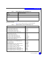
The definition of oversubscription can vary by vendor. E-Lab's
definition is: the ratio of bandwidth required to bandwidth available.
When all ports, associated pair-wise, in any random fashion, cannot
sustain full duplex at full line-rate, the switch is oversubscribed.
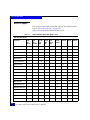
E-Lab's oversubscription analysis of the current Connectrix Director
product set is provided in Table 1.
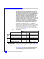
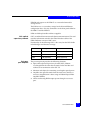
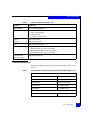
Table 1
Oversubscription
Chassis
2 Gb/s
4 Gb/s
Measurements
ED-10000M
ED-140M
ED-48000B
MDS 9513
Maximum non-oversubscribed port count
256
140
256
264
Maximum oversubscribed port count
N/A
N/A
N/A
528
Oversubscription ratio at max config
N/A
N/A
N/A
2:1
Maximum non-oversubscribed port count
128
70
128
132
Maximum oversubscribed port count
256
140
256
528
Oversubscription ratio at max config
2:1
2:1
16:8
4:1
EMC Support Matrix
and E-Lab
Interoperability
Navigator
For the most up-to-date information, always consult the EMC Support
Matrix (ESM), available through E-Lab Interoperability Navigator
(ELN), at: http://elabnavigator.EMC.com, under the PDFs and
Guides tab.
The EMC Support Matrix links within this topology guide will take
you to Powerlink where you are asked to log in to the E-Lab
Interoperability Navigator. Instructions on how to best use the ELN
14
Non-EMC SAN Products Data Reference Manaul
(tutorial, queries, wizards) are provided below this Log in window. If
you are unfamiliar with finding information on this site, please read
these instructions before proceeding any further.
Under the PDFs and Guides tab resides a collection of printable
resources for reference or download. All of the matrices, including
the ESM (which does not include most software), are subsets of the
E-Lab Interoperability Navigator database. Included under this tab
are:
◆
The EMC Support Matrix, a complete guide to interoperable, and
supportable, configurations.
◆
Subset matrices for specific storage families, server families,
operating systems or software product.
◆
Host connectivity guides for complete, authoritative information
on how to configure hosts effectively for various storage
environments.
Under the PDFs and Guides tab, consult the Internet Protocol pdf
under the "Miscellaneous" heading for EMC's policies and
requirements for the EMC Support Matrix.
Related
documentation
Related documents include:
◆
The EMC Networked Storage Topology Guide has been divided into
several TechBooks and reference manuals. The following
documents, including this one, are available through the E-Lab
Interoperability Navigator, Topology Resource Center tab, at
http://elabnavigator.EMC.com.
• Backup and Recovery in a SAN TechBook
• Building Secure SANs TechBook
• Extended Distance Technologies TechBook
• Fibre Channel over Ethernet (FCoE): Data Center Bridging (DCB)
Concepts and Protocols TechBook
• Fibre Channel SAN Topologies TechBook
• iSCSI SAN Topologies TechBook
• Networked Storage Concepts and Protocols TechBook
• Storage Virtualization and Replication Technologies TechBook
• WAN Optimization Controller Technologies TechBook
• EMC Connectrix SAN Products Data Reference Manual
• Legacy SAN Technologies Reference Manual
Non-EMC SAN Products Data Reference Manaul
15
• Non-EMC SAN Products Data Reference Manual
◆
EMC Support Matrix, available through E-Lab Interoperability
Navigator at http://elabnavigator.EMC.com >PDFs and Guides
◆
RSA security solutions documentation, which can be found at
http://RSA.com > Content Library
All of the following documentation and release notes can be found at
http://Powerlink.EMC.com. From the toolbar, select Support >
Technical Documentation and Advisories, then choose the
appropriate Hardware/Platforms, Software, or Host
Connectivity/HBAs documentation links.
Hardware documents and release notes include those on:
◆
◆
◆
◆
◆
◆
Connectrix B series
Connectrix M series
Connectrix MDS (release notes only)
CLARiiON
Celerra
Symmetrix
Software documents include those on:
◆
◆
◆
◆
◆
EMC Ionix ControlCenter
RecoverPoint
Invista
TimeFinder
PowerPath
The following E-Lab documentation is also available:
◆
◆
Host Connectivity Guides
HBA Guides
For Cisco and Brocade documentation, refer to the vendor’s website.
Authors of this
TechBook
◆
http://cisco.com
◆
http://brocade.com
This TechBook was authored by Mark Lippitt, Erik Smith, Erik Paine,
and Mark De Castro with contributions from the following EMC
employees: Kieran Desmond, Ger Halligan, and Ron Stern, along
with other EMC engineers, EMC field personnel, and partners.
Mark Lippit is a Technical Director in EMC E-Lab with over 30 years
experience in the storage industry, including Engineering and
Marketing roles at Data General, Tandem Computers, and EMC.
Mark initiated and led the Stampede project in 1997, which became
16
Non-EMC SAN Products Data Reference Manaul
EMC's first Connectrix offering. Mark is an active T11 participant, a
committee within the InterNational Committee for Information
Technology Standards, responsible for Fibre Channel Interfaces.
Erik Smith is a Consultant Systems Integration Engineer and has
been with EMC for over 12 years. For the past 6 years, Erik has
worked in the E-Lab qualifying new FC switch hardware, firmware,
and management application revisions, in addition to being a major
contributor to the Topology Guide. Erik is one of the founding
members of the original SAN team in Technical Support. Erik is a
member of T11.
Erik Paine is a Principal Systems Integration Engineer and has been
with EMC for over 11 years. Erik transferred to E-Lab with a strong
networking background spanning over 20 years, including time
spent at BBN Inc., Tufts University, and numerous engineering roles
within EMC. Erik is using his networking and Ethernet knowledge to
help qualify and integrate the emerging storage technologies utilizing
Ethernet as a medium.
Mark Anthony P. De Castro is a Senior System Integration Engineer
in EMC E-Lab with over 7 years of experience in the networking
industry, including engineering, provisioning, implementation, and
support roles. Prior to joining EMC in 2008, Mark worked at the Cisco
Technical Assistance Center, AT&T in Singapore, and BT in
Singapore. He holds a Bachelor’s degree in Computer Science and is
a Cisco Certified Network Professional (CCNP) and Cisco Certified
Internet Professional (CCIP).
Conventions used in
this document
!
EMC uses the following conventions for special notices:
CAUTION
CAUTION, used with the safety alert symbol, indicates a
hazardous situation which, if not avoided, could result in minor or
moderate injury.
!
IMPORTANT
An important notice contains information essential to software or
hardware operation.
Note: A note presents information that is important, but not hazard-related.
Non-EMC SAN Products Data Reference Manaul
17
Typographical conventions
EMC uses the following type style conventions in this document.
Normal
Used in running (nonprocedural) text for:
• Names of interface elements (such as names of windows,
dialog boxes, buttons, fields, and menus)
• Names of resources, attributes, pools, Boolean expressions,
buttons, DQL statements, keywords, clauses, environment
variables, functions, utilities
• URLs, pathnames, filenames, directory names, computer
names, filenames, links, groups, service keys, file systems,
notifications
Bold
Used in running (nonprocedural) text for:
• Names of commands, daemons, options, programs,
processes, services, applications, utilities, kernels,
notifications, system calls, man pages
Used in procedures for:
• Names of interface elements (such as names of windows,
dialog boxes, buttons, fields, and menus)
• What user specifically selects, clicks, presses, or types
18
Italic
Used in all text (including procedures) for:
• Full titles of publications referenced in text
• Emphasis (for example a new term)
• Variables
Courier
Used for:
• System output, such as an error message or script
• URLs, complete paths, filenames, prompts, and syntax when
shown outside of running text
Courier bold
Used for:
• Specific user input (such as commands)
Courier italic
Used in procedures for:
• Variables on command line
• User input variables
<>
Angle brackets enclose parameter or variable values supplied by
the user
[]
Square brackets enclose optional values
|
Vertical bar indicates alternate selections - the bar means “or”
{}
Braces indicate content that you must specify (that is, x or y or z)
...
Ellipses indicate nonessential information omitted from the
example
Non-EMC SAN Products Data Reference Manaul
Where to get help
EMC support, product, and licensing information can be obtained as
follows.
Product information — For documentation, release notes, software
updates, or for information about EMC products, licensing, and
service, go to the EMC Powerlink website (registration required) at:
http://Powerlink.EMC.com
Technical support — For technical support, go to Powerlink and
choose Support. On the Support page, you will see several options,
including one for making a service request. Note that to open a
service request, you must have a valid support agreement. Please
contact your EMC sales representative for details about obtaining a
valid support agreement or with questions about your account.
We'd like to hear from you!
Your feedback on our TechBooks is important to us! We want our
books to be as helpful and relevant as possible, so please feel free to
send us your comments, opinions and thoughts on this or any other
TechBook:
[email protected]
Non-EMC SAN Products Data Reference Manaul
19
20
Non-EMC SAN Products Data Reference Manaul
1
CNT/Inrange Switches
and Directors
This chapter contains information on CNT/Inrange switches and
directors.
◆
CNT/Inrange FC/9000 ..................................................................... 22
Note: For information on EMC® qualified third-party products, refer to the
EMC Select document on Powerlink.
CNT/Inrange Switches and Directors
21
CNT/Inrange Switches and Directors
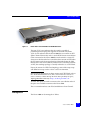
CNT/Inrange FC/9000
The CNT/Inrange FC/9000 64 is a Fibre Channel Enterprise Director,
scalable from 24 ports to 64 ports. E-Lab Navigator lists the
configurations supported by the FC/9000.
The FC/9000 can be used in a high-speed SAN designed to support
data-intensive high-availability applications, such as backup and
recovery, business continuance, and data and resource sharing.
Note: FICON and distance testing are not complete.
Fabric Management is performed by the IN-VSN Enterprise Manager
in a client/server architecture installed on a PC, usually housed in or
near the FC/9000 Director cabinet.
E-Lab Navigator lists specific versions of supported firmware, as well
as fabric topology constraints associated with the FC9000.
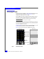
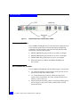
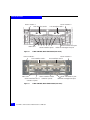
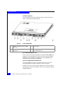
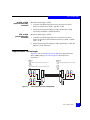
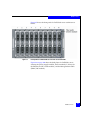
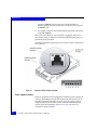
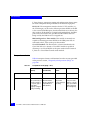
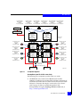
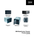
Figure 1 shows the CNT/Inrange FC/9000 Director cabinet.
Front view
Rear view
FCM module
Ethernet port
FSW modules
FIO modules
Ethernet port
Board
releases
Fan assembly
Cable trough
Figure 1
22
Power switches
CNT/Inrange FC/9000
Non-EMC SAN Products Data Reference Manaul
Power connectors
CNT/Inrange Switches and Directors
Component overview
FIO (FC/9000 XCAF or base I/O module)
FIO modules provide the physical connectivity between the FC/9000
backplane and the external devices connected to the FC/9000. The
FC/9000 supports a minimum (base) configuration of three base FIO
modules and a maximum of eight per chassis.
FIO modules are hot-swappable, containing a single processor,
supporting memory, reset button, and front panel indictors to show
current status: temperature, heartbeat, logged in/out, and activity
(traffic).
The Extended Credit Addressing Facility (XCAF) FIO has two
features: the ability to provide 64 buffer-to-buffer credits and FICON
addressing.
Blank panels must be inserted where FIO modules are not present.
FSW (FC/9000 switching module)
FSW modules provide the physical and logical connectivity between
FIO modules installed in the chassis. These modules provide the
middle or cross-connect stage of the switch architecture.
The FC/9000 supports a minimum (base) configuration of four FSW
modules and maximum of five (high-availability configuration) per
chassis, with only four FSW on line at any time.
FSW modules are hot-swappable, containing a single processor,
supporting memory, reset button, and front panel indictors to show
current status: temperature, heartbeat, and activity (on line or off
line).
Blank panels must be inserted where FSW modules are not present.
FCM (FC/9000 control module)
FCM modules provide the common control interface for the FC/9000
system. This module acts a proxy for all external communication to
other modules from the IN-VSN Enterprise Manager. The FC/9000
requires a minimum of one FCM, or can have a maximum two for
redundancy.
Each hot-swappable FCM module contains a single processor,
supporting memory, reset button, and front panel indictors to show
status: link, data, 100 Mb/s, online/offline, primary board, fault,
4-character display window.
CNT/Inrange FC/9000
23
CNT/Inrange Switches and Directors
Blank panels must be inserted where FCM modules are not present.
Power supply assembly
Power supplies are located in the front left and right sides of the
chassis. The power supplies are hot swappable, redundant, and load
sharing. The on/off switches are located in the front lower section of
the switch.
Fan module assembly
A fan assembly in the rear of the chassis provides cooling for the
FC/9000, drawing air through and pushing air out. In the event of a
single fan failure, the remaining three fans will accelerate to maintain
the cooling process. These fans are replaceable either within a unit or
the entire unit (pair).
Backplane module
The backplane provides connectivity among all system modules,
including the FIO, FSW, FCM, power supply, and fans. The backplane
can be expanded with a special wiring harness and dipswitch
configuration to provide connectivity for 128 ports.
The backplane provides:
◆
Port-to-port bus connection
◆
Interprocess communication at 100 Mb/s with redundancy
◆
Connection to expansion interface modules
◆
Power distribution bus connectivity
◆
Power supply alarm signals
◆
DC fail status
◆
AC fail status
◆
Power supply present status
◆
Fan status and control
◆
Slot geographical addressing
◆
Miscellaneous status and control
IN-VSN Enterprise Manager
The IN-VSN Enterprise Manager is the GUI used to manage the
FC/9000. It is a software application that has two components based
on a client/server architecture. The client periodically (every five
seconds) polls the server through Ethernet (10/100 Mb/s) to send
and retrieve changes to the FC/9000.
24
Non-EMC SAN Products Data Reference Manaul
CNT/Inrange Switches and Directors
The IN-VSN Enterprise Manager Client can:
◆
Define module and port configurations
◆
Define zoning
◆
Monitor alarms
◆
Monitor system performance
◆
Invoke system diagnostics
◆
Implement some director parameters
The IN-VSN Enterprise Manager's client software application
operates on Windows NT and Windows 2000 Professional platforms.
The IN-VSN Enterprise Manager server software application requires
a dedicated PC, operates on Windows NT and Windows 2000
Professional platforms, and has basic hardware compatibility
requirements from CNT/Inrange. The server communicates with the
FCM module through Ethernet (10/100 Mb/s) to send and retrieve
changes to/from the FC/9000.
Features overview
Features of the CNT/Inrange FC/9000 include:
◆
High availability: fully redundant internal pathing, power,
cooling and control; no single point of failure
◆
Non-disruptive code loads and hot-swappable GBICs
◆
Auto-discovering, self-configuring 1.0625 Gb ports; arbitrated
loop (FC-AL), transitive loop (TL), switched fabric (FC-SW)
◆
Enterprise Manager SAN fabric management system IN-VSN
Enterprise Manager
◆
Employment of orphan zoning by zoning, hard zoning, port
zoning, and broadcast zoning, to guard against losing ports not
proactively assigned to a defined zone
◆
Phone-home and pager direct-dial feature
◆
Statistical and diagnostic monitoring
◆
Class 2,3 Fibre Channel environments
◆
64 ports available through 8-port I/O modules (8 ports per FIO
module)
◆
GBIC Port Module (SE form factor) available in multimode fiber
(shortwave)
CNT/Inrange FC/9000
25
CNT/Inrange Switches and Directors
◆
64 buffer-to-buffer credits (BB_Credits) available per port
◆
Support for Class 2 and Class 3 Fibre Channel protocols
◆
Auto-negotiate function on all ports, to provide either switched
F_Port or T_Port connections
◆
Full duplex 100 MB/s data rate per Fibre Channel port
◆
Supported port types: F_Port, FL_Port, TL_Port
Director Management (IN-VSN Enterprise Manager)
The IN-VSN Enterprise Manager:
◆
Provides centralized monitoring and control of multiple fabrics
and all vital network functions from a single console. Using a
Java-based and/or SNMP interface, multiple concurrent users
can access levels of fabric information ranging from basic
monitoring and configuration information to detailed
performance data. Enterprise Manager is a configuration tool, as
well as an application for management of SAN configuration,
application and performance.
◆
Allows centralized configuration and management of fabric using
client/server architecture.
◆
PC Management Server allows Server functionality and Client.
◆
Supports Windows NT 4.0 and Windows 2000 Professional
Clients.
◆
Allows centralized management of Director.
◆
Provides support for online, nondisruptive code upgrades.
◆
Features 10/100 Mb Ethernet connections to FCM for out-of-band
management.
◆
Provides extensive centralized logging: Event, Audit, Session
logs, and SNMP support.
Availability management
Availability management includes:
◆
26
Management system helps you track the status of redundant
power, cooling, and control.
Non-EMC SAN Products Data Reference Manaul
CNT/Inrange Switches and Directors
◆
Phone home/email home provides instant notification of system
or network issues.
◆
Front panel display allows quick check of fan operation,
temperature, and port status.
Performance management
Performance management includes:
◆
Dynamic statistics display performance data for each online port.
◆
Zoning of FC/9000 ports allows efficient and secure
communication among nodes.
◆
Event Log and Audit Log streamline the troubleshooting process
and provide rapid error source identification.
◆
SNMP traps show whether defined limits have been exceeded.
References
Note the following for more information:
◆
http://www.cnt.com x
◆
IN-VSM FC9000 Fibre Channel Director Installation Manual
◆
IN-VSM FC9000 Fibre Channel Director Maintenance Manual
◆
IN-VSM FC9000 Fibre Channel Director Installation and Operation
Manual
◆
IN-VSM FC9000 Fibre Channel Director Site Planning Guide Manual
CNT/Inrange FC/9000
27
CNT/Inrange Switches and Directors
28
Non-EMC SAN Products Data Reference Manaul
2
Nortel OPTera Metro
This chapter contains information on the Nortel OPTera Metro
platform.
◆
◆
◆
◆
◆
Introduction ........................................................................................
Available OPTera Metro topologies.................................................
Nortel OPTera protection scheme....................................................
Power budget calculations................................................................
Diagnostics and maintenance ..........................................................
30
32
33
34
36
Note: For information on EMC-qualified third-party products, refer to the
EMC Select document on Powerlink.
Nortel OPTera Metro
29
Nortel OPTera Metro
Introduction
The Nortel OPTera Metro platform is a true protocol- and
bit-rate-independent fiber-optic transport system. The OPTera Metro
supports the following protocols: SONET, ATM, Gigabit Ethernet, IP,
FDDI, and all optical interfaces (OC-n).
Note these capacities:
◆
An ETSI- and NEBS-compliant unit, the OPTera Metro shelf can
accommodate up to 10 Gb/s of capacity in less than 2 cubic feet of
space.
◆
An OPTera Metro system can have one to eight pairs of shelves at
multiple sites configured in a hubbed ring or point-to-point
topology. Each site can have one or more shelves.
◆
A fully loaded system (16 shelves) can transport up to 32
protected or 64 unprotected channels (wavelengths) over each
optical fiber.
◆
Each channel can operate from 50 Mb/s to 2.5 Gb/s. This allows a
total transport capacity of 80 Gb/s.
A shelf is a basic building block of a Nortel OPTera DWDM system. A
shelf contains a subsystem of components that convert optical signals
into electrical, allow adding and dropping functionality, and multiplex
and pass signals through the network.
A Nortel OPTera shelf holds:
◆
Optical Channel Interface (OCI); provides signal interface card.
◆
Optical Channel Laser and Detector (OLCD)
◆
Optical Channel Manager (OCM)
◆
Optical Multiplexer (OMX); provides add/drop filtering (ADF) to
multiplex each OCLD optical wavelength signal onto the single
mode fiber.
◆
Shelf Processor (SP); provides monitoring and control
functionality.
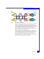
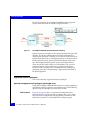
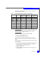
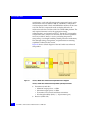
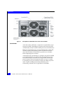
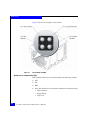
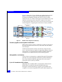
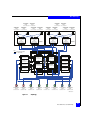
Figure 2 on page 31 shows an example of a Nortel OPTera shelf.
30
Non-EMC SAN Products Data Reference Manaul
Nortel OPTera Metro
Device
interfaces
Darkfiber
network
Add
Tx
Rx
OCI
A
OCM
A
Backplane
OCLD
W
Drop
OMX
W
Tx
Rx
OMX
E
Tx
Rx
Backplane
Add
Tx
Rx
Figure 2
OCI
B
OCM
B
OCLD
E
Drop
Nortel OPTera shelf diagram
The OCI interface provides the necessary connections to connect the
OPTera to customer traffic. There are two types of OCI card(s):
1.25 Gb/s and 622 Mb/s. The Optical Channel and Detector (OCLD)
receives electrical client signal from the back plane, converts electrical
signal to DWDM wavelength, and provides 32-channel fault
monitoring and two Fibre Channel optical connectors (connected to
Fibre Channel pigtails from OMX modules).
The optical signals from the DWDM network are converted into
electrical signals only on the shelf that drops them, creating a logical
point-to-point topology between two shelves that carry the same
optical wavelength band. (At least two shelves with the same
wavelength band in two locations of the network are necessary.) All
other bands pass through the shelf's optical filters.
Introduction
31
Nortel OPTera Metro
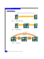
Available OPTera Metro topologies
The point-to-point configuration (which is the basis for all other
configurations) will include a local and remote site. The data will
flow between the different sites using two links. Each link includes a
transmit and receive single-mode fiber cable (dark fiber). The two
links are usually described as east-to-west or west-to-east. The cabinets
usually contain four shelves or bands, which make up the site.
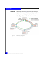
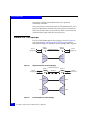
Figure 3 and Figure 4 show possible OPTera Metro DWDM
topologies.
Terminal 2
Terminal 1
Figure 3
1
1
2
2
3
3
Point-to-point protected topology
Hub site
1
Remote site
3
2
3
Remote site
1
2
Figure 4
32
Hubbed ring topology
Non-EMC SAN Products Data Reference Manaul
Nortel OPTera Metro
Nortel OPTera protection scheme
A protected channel connects an attaching device interface by using a
single OCI card and two OCLD cards (each having the same
wavelength) in one shelf of the shelf pair to two corresponding
OCLD cards (each having the same wavelength) and a single OCI
card in the second shelf of the shelf pair. The data flow between the
OCI card and two OCLD cards within each shelf is managed by the
two Optical Channel Manager (OCM) cards in each shelf.
This scheme creates two data paths inside the DWDM network. One
path is active as long as signal integrity is maintained by the physical
connections. Any disruption will fail over to the alternate data path
using the second OCLD pair.
Note that this configuration neutralizes and single OCI, one on each
shelf. A mixture of protected and unprotected channels is available in
a single shelf.
Nortel OPTera protection scheme
33
Nortel OPTera Metro
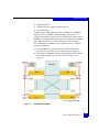
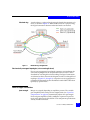
Power budget calculations
Calculate the power budget as shown in the following example.
B
OC-12(1)-P
OC-3(1)-P
OC-12(3)-P
OC-12(2)-P
Gbe(2)-P
Gbe(1)-P
Hub site
DCN
1
2
PC
Gateway IP address
3
4 dB
6 dB
Remote site B
3
OC-3(1)-P
Remote site A
2
2 dB
OC-12(1)-P
OC-12(3)-P
OC-12(2)-P
Figure 5
1
Gbe(2)-P
Gbe(1)-P
OPTera protection scheme
Note that this is only an approximation, and that a site survey is
required before activation:
1. Fiber losses are calculated according to the distances times the
specifications of the fiber cable. In this case 0.2 dB per km, so for
the 30 km leg (30 km * 0.4 dB/km = 6 dB loss).
2. Each connector has approximately 0.5 dB loss per connector.
3. Add up all of the fiber losses, on all three legs, with the connector
losses:
6 dB + 2 dB + 4 dB + (0.5 dB * 6) = 15 dB
34
Non-EMC SAN Products Data Reference Manaul
Nortel OPTera Metro
4. Add repair margin (10%): 15dB + 1.5 dB = 16.5 dB.
5. With a Maximum Link Budget (see Nortel OPTera end-of-life
chart): 18.3 dB. Subtract total link budget (16.5 dB) from
Maximum Link Budget (18.3 dB) and if result is Positive (1.8 dB),
then link budget is within parameters.
Power budget calculations
35
Nortel OPTera Metro
Diagnostics and maintenance
For configuration, power budget calculation and troubleshooting
details, consult the Nortel OPTera Metro technical publications.
Using the Symmetrix Fibre Channel director online utilities can
complement repair and system diagnostics.
36
Non-EMC SAN Products Data Reference Manaul
3
Ciena Products Data
This chapter contains data on Ciena products.
◆
◆
◆
Ciena ONLINE7000 ........................................................................... 38
Ciena CN 4200/CN4200 MC ............................................................ 48
CIENA CN 2000 ................................................................................. 63
Note: For information on EMC-qualified third-party products, refer to the
EMC Select document on Powerlink.
Ciena Products Data
37
Ciena Products Data
Ciena ONLINE7000
The Ciena ONLINE7000 platform is a true protocol and
bit-rate-independent fiber-optic transport system that supports the
following protocols:
◆
◆
◆
◆
◆
◆
◆
◆
◆
SONET/SDH
IP
Ethernet
GbE
Fibre Channel
FDDI
ESCON
FICON
ATM
The ONLINE7000 backplane is utilized for management (FCAPS
capability: Fault Configuration, Administration, Provisioning and
Service).
The ONLINE7000 platform offers the following:
◆
Up to 33 protected wavelengths and 66 unprotected wavelengths
◆
Client interface through a Software Provisionable Transceiver:
OC-3/12/48 (STM-1/4/16), GbE
◆
Bitrate Flexible Transceiver: 100 Mb/s to 2.5 Gb/s, including
Fibre Channel, FICON, ESCON, D1 Video, HDTV, FDDI, Fast
Ethernet, ATM, IP for long distance applications
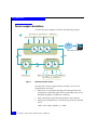
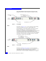
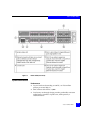
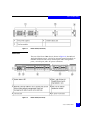
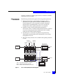
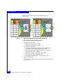
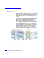
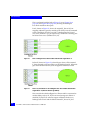
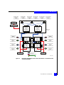
Figure 6 on page 39 is a general UPSR protection diagram of a single
Network Element (shelf) consisting of a general Main Shelf without
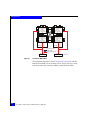
Expansion shelf, accompanied by a top-down I/O flowchart (Figure 7
on page 40) in conjunction with card descriptions used for a
two-node point-to-point/two-node ring configuration over extended
distance.
38
Non-EMC SAN Products Data Reference Manaul
Ciena Products Data
BWDM
WPSU X-OSC
CWDM
X-OSC
PEM
WCI
POST
PSM AMP
GRDM
PRE
AMP
CWDM
GWDM BWDM
Power
Power
Alarm
Alarm
1
Figure 6
2
3
4
5
6
7
8
9
10 11 12 13 14 15 16 17 18
ONLINE7000 UPSR protection diagram for main shelf
Within the ONLINE7000 Network Element the cards are housed in at
least two areas (Main Shelf and one or more Expansion Shelves) of a
single DWDM node. The complexity and density of the multiplexing
(number of GRDM cards) circuits determine the number of shelves
utilized within the DWDM configuration.
Ciena ONLINE7000
39
Ciena Products Data
Fibre Channel
switch
ISLs
ONLINE7000
east
<local>
GRDM
Network element 1
WPSU
WCI
WCI
CWDM
CWDM
PEM
PSM
BWDM
AMP
BWDM
OSC
OSC
AMP
Maximum
distance
working
Maximum
distance
protection
AMP
OSC
OSC
AMP
BWDM
BWDM
PEM
PSM
CWDM
CWDM
WCI
WCI
ONLINE7000
west
<remote>
WPSU
Network element 2
GRDM
ISLs
Fibre Channel
switch
Figure 7
40
I/O flowchart: Point-to-point/ring configuration over extended
distance
Non-EMC SAN Products Data Reference Manaul
Ciena Products Data
ONLINE7000 card types
Note: All ports available on the following cards require MU cables.
GRDM CP: gigabit rate
data mux circuit pack
GRDM cards are used for point-to-point traffic connections, and must
be used in conjunction with 3RWCI CPs (Wave Channel Interface
Circuit Packs responsible for Regeneration, Reshape, Retime of
optical signals) by multiplexing two Gigabit Ethernet (GbE) or two
Fibre Channel Channels MU ports (or tributaries) into a single (Tx,
Rx) wavelength for transport across the ONLINE7000/9000/11000
system.
Conceptually bypassing the GRDM card is allowed, since WCIs
support OC-48 bitrate capacity. However, Fibre Channel uses 1.0625
Gb/s, and WCIs accept only one port. GRDM accepts two ports and
allows FC/GigE Performance monitoring.
The GRDM card accepts only MU Fibre Channel connections. GRDM
will accept shortwave 850nm and longwave 1310nm connections.
SC-to-MU cable converters are required in order to attach to
EMC-supported switches.
Note: When an 850nm wavelength enters the GRDM, the wavelength out of
the GRDM will be increased from 850nm to 1310nm.
Note: Do not mix protocols on the same GRDM card. (For example, Port 1
cannot use GbE if Port 2 uses Fibre Channel.)
WPSU: working
protection splitter unit
Note: WPSUs are used in unidirectional path switched ring configurations
(redundant path, redundant band with dedicated protection).
UPSR cards use optical couplers that have either one of these two
capabilities:
◆
Splits a single (Tx, Rx) wavelength input from the GRDM card to
two identical wavelengths utilized for working and protection
lines.
◆
Combines two optical incoming signals into one output.
Direct connection to a WPSU is possible if the input received is an
MU type OC-3 or 12 or OC-48 bandwidth connection.
Ciena ONLINE7000
41
Ciena Products Data
WCI: wave converter
interface (SONET/SDH
input if there are no
GRDMs)
The WCI converts the optical signal received by the WPSU card to an
electrical pulse, and back again to an optical signal. WCI converts the
1310nm impulse from the WPSU to a frequency band (1530 to
1563.1 nm) utilized by the ONLINE7000.
Note: WCI supports up to 80 km.
Note: The number of WCIs should be double the number of GRDM cards in a
UPSR protection configuration.
Note: WCI3RL is a card with 3R (reshape, regeneration, retime) capability,
along with 160 km extended reach going from customer premise equipment
to the WCI3RL.
42
CWDM: channel wave
division multiplexer
The CWDM multiplexes up to three different wavelengths received
from WCI cards into a single band and reroutes the single band to a
CWDM on Network Element 1 of a two-node point-to-point
connection. On the other side of the ring (Network Element 2 of a
two-node point-to-point connection), CWDM demuxes the single
band into a maximum of three different channels with the same band.
CWDMs can also demultiplex the input of a BWDM to wavelength
outputs to several WCI cards.
BWDM: band wave
division multiplexer
This card multiplexes (adds) a band of three wavelengths coming
from the CWDM and demultiplexes (drops) a band coming from the
pre-amp. Working-line bands are in the range 1 through 5, and
protection-line bands are 7 through 11.
Pre-amp:
pre-amplifier
The pre-amp amplifies optical signals entering the node. The
pre-amp is used in conjunction with a post-amp to compensate for
signal loss caused by long spans between nodes, or it is used in
conjunction with the Line CP if no post-amp is required in that span.
pre-amps are field-replaceable and hot-swappable.
PEM: processor
element module
PEMs contain the Software Application/Firmware on the Network
Element (ONLINE7000). PEMs between multiple Network Elements
share the same Global database (user privileges, circuits, Network
Element configuration information, etc.) tables.
PSM: persistent
storage module
PSMs contain nonvolatile storage of configuration and status
information for the node. The PSM data store is implemented in Flash
Non-EMC SAN Products Data Reference Manaul
Ciena Products Data
EPROM and appears to the PEM CP as a networked removable
storage device.
The PSM serves as a secondary storage for the Network Element
configuration data. Also, the connections on the front panel differ for
the PSM CP and the PEM CP.
PSMs are field-replaceable and hot-swappable.
OSC: optical
supervisory channel
OSCs are utilized for internetwork element communication. This card
transfers information stored in the Global database tables of the
PEMs. Different versions of OSCs exist.
Functionality of the following OSCs is the same, but the OSCs differ
in link budgets and distance coverage:
Post-amp:
post-amplifier
OSC
Link budget
Distance
OSC
25 dB
80 km
OSCE
35 dB
110 km
X-OSC
35 dB (approximate)
120 km (approximate)
The post-amp circuit provides the following functions:
◆
Splits off the Optical Supervisory channel (OSC) 1510 nm
wavelength from the other data channels on the line fiber and
redirects it for termination at the OSC CP.
◆
Monitors and adjusts the remaining wavelengths optical power.
◆
Amplifies the optical channels from the node out to the line as
necessary. Amplification is done using an Erbium-Doped Fiber
Amplifier (EDFA).
◆
Allows monitoring EDFA output power through a test-access
port.
Ciena ONLINE7000
43
Ciena Products Data
ONLINE7000 topologies
The ONLINE7000 supports the following three topologies:
Line
east
East
mux
Line
west
West
mux
West terminal
East terminal
Figure 8
Point-to-point topology
Line
east
East
mux
Line
west
West
mux
ADM terminal
West terminal
Figure 9
Line
west
West
mux
Line
west
West
mux
Line
east
East
mux
ADM terminal
West terminal
44
Line
west
West
mux
East terminal
Line drop mode
Line
east
East
mux
Figure 10
Line
east
East
mux
Ring network
Non-EMC SAN Products Data Reference Manaul
Line
west
West
mux
Line
east
East
mux
East terminal
Ciena Products Data
ONLINE7000 protection scheme
The ONLINE7000 employs O-UPSR (Optical–Unidirectional Path
Switched Ring) for data protection. In an O-UPSR ring, traffic is
duplicated and sent around both sides of the ring simultaneously.
Note: The generic term for O-UPSR is ODPR (Optical Dedicated Protection
Ring).
O-UPSR restoration is performed on a per-channel basis at those
nodes where the channel enters or exits the ring (rather than at the
intervening nodes). The destination node selects the better of the two
signals and forwards the traffic to the subtending equipment.
Typically, the working path is selected unless it has failed or
degraded. In the case of a failure or degradation, the destination node
performs restoration by selecting the protected path.
Inner fiber carries
optical signals in a
clockwise direction
Outer fiber carries
optical signals in a
counterclockwise direction
NE 1
NE 4
NE 2
NE 3
Figure 11
O-UPSR ring configuration in normal mode
Ciena ONLINE7000
45
Ciena Products Data
NE 1
NE 4
NE 2
NE 3
Figure 12
O-UPSR ring configuration in failure mode
Note: Optical UPSR dedicated protection: redundant path and bands.
Note: ONLINE7000 supports a maximum of 33 wavelengths utilizing a
WPSU splitter on the tributary incoming links.
ONLINE7000 power budget calculations
The link budget needed for the ONLINE7000 to function must fall
within the range of 33 dB or less. Ciena’s power budget calculation is:
<LINK BUDGET> =
46
Non-EMC SAN Products Data Reference Manaul
[0.3 dB/km * <km fiber used>] +
[0.5 * (number of connects)] +
[<km fiber used> * 0.1 dB/km] + 1.0 dB
Ciena Products Data
Where:
• <number of connects> = [number of Cross-connects +
termination].
• <0.1 dB/km> is used to calculate the Maintenance Margin.
ONLINE7000 diagnostics and maintenance
For configuration, power budget calculation, and troubleshooting
details, consult the Ciena technical publications.
Additional information regarding the ONLINE7000 is accessible at
http://www.ciena.com.
Ciena ONLINE7000
47
Ciena Products Data
Ciena CN 4200/CN4200 MC
Ciena CN 4200 and Ciena CN 4200 MC Advanced Services Platforms
are multiservice switching, aggregation, and transport systems that
allow carriers to groom, switch, and transpond a diversity of
sub-wavelength client services onto higher-speed OTU1 (2.7 Gb/s)
and OTU2 (10.7 Gb/s) transport streams. Using innovative timeslot
technology, these service platforms can support a multitude of both
like and unlike services. They can also directly transpond a variety of
10G services such as 10 GbE LAN/WAN PHY, 10G FC/FC1200 and
OC-192/STM-64 into OTU2.
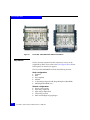
Figure 13
Ciena CN 4200 FlexSelect Advanced Services Platform
The full list of supported services includes:
48
◆
10/100BaseT (supports jumbo frames)
◆
ESCON
◆
Fibre Channel, FC100, FC200, FC400, and 10G FC/FC1200
◆
FICON, both 1 G and 2 G
◆
Gigabit Ethernet and 1000BaseT (supports jumbo frames)
◆
OC-3/12/48/192
◆
STM-1/4/16/64
Non-EMC SAN Products Data Reference Manaul
Ciena Products Data
◆
10 GbE WAN PHY
◆
10 GbE LAN PHY (supports jumbo frames1)
◆
OTU1 and OTU2
For higher optical fiber efficiencies, the CN 4200 and CN 4200 MC
support in-chassis CWDM and DWDM filters. These filters are
designed in a modular fashion and accommodate growth up to 40
DWDM or 8 CWDM channels without service interruption. DWDM
and CWDM channels can even be combined on the same fiber.
The CN 4200 and CN 4200 MC service platforms share a common
transport architecture.
Figure 14
◆
The CN 4200 has four line card slots, each delivering client
connectivity using OTU1 and/or OTU2 transport (Figure 14).
◆
The smaller CN 4200 MC, which is intended for more focused site
service requirements, has two line card slots (Figure 15 on
page 50).
CN 4200 block diagram
Ciena CN 4200/CN4200 MC
49
Ciena Products Data
Figure 15
CN 4200 MC block diagram
Both systems employ a distributed switch architecture that provides
sufficient grooming capability for stand-alone applications, yet is
optimized for aggregation of services onto OTU1 and OTU2
wavelengths. Optional redundancy of interfaces and common
elements guarantee operator-class service availability, with less than
25 ms automatic protection switching, faster than SONET/SDH.
Client service identities (e.g., ESCON, 1000BaseT) are
software-provisionable rather than determined at the hardware layer,
thereby offering a wide mix of services on the same card. The CN
4200 delivers standardized and rigorous performance monitoring
metrics for all supported client services.
The CN 4200 and CN 4200 MC systems give operators a scalable
solution for delivering multiservice transport and offer the following
key features:
50
◆
High density multiservice transport platform supporting
CWDM/DWDM
◆
Flexible assignment of ports as client or network ports
◆
Extensive performance monitoring on all client and network
services
◆
Service-level loopbacks for fault isolation
◆
Front chassis accessibility for all connections and servicing
Non-EMC SAN Products Data Reference Manaul
Ciena Products Data
Available modules
This section provides information on available modules.
◆
“M6S/M3S” on page 51
◆
“F10-T” on page 51
◆
“F10-A” on page 52
◆
“FC4-T” on page 52
◆
“Optical Protection Switch (OPS) modules” on page 53
◆
“Optical Amplifier (OA) modules” on page 54
◆
“Optical Supervisory Channel (OSC) module” on page 55
M6S/M3S
The M6S is a 6-port multiservice module with programmable
interfaces using SFP pluggable optics. Each port can be provisioned
with its own service identity. The M3S is a 3-port version of the same
module. Each M6S/M3S also contains a switch fabric.
Figure 16
M6S module
The three RJ-45 ports (MGMT-1, -2, and CNSL) are used for remote
and local management purposes, are accessible through the module’s
faceplate, and are only active if the module is functioning as the
system controller. (Please note that although MGMT-1, -2 and CNSL
are present in this figure, this is not an OA card.)
F10-T
The F10-T module (Figure 17 on page 52) is a highly-adaptable
transponder/regenerator card designed exclusively for 10G services.
It is equipped with two full-duplex optical ports, a pluggable XFP
transceiver port, and a network port implemented in discrete DWDM
Ciena CN 4200/CN4200 MC
51
Ciena Products Data
optics and intended for long-range transport. This port can be
equipped with either a fixed or tunable wavelength transmitter.
Figure 17
F10-T module
F10-A
The F10-A card (Figure 18) is a service aggregation and grooming
module that combines 2.5G services (such as ODU1 and
OC-48/STM-16), as well as time-slotted services (such as Gigabit
Ethernet and FC200), into a G.709 OTU2 stream. External
connectivity is provided by two pluggable SFP transceiver ports and
a network port implemented in discrete DWDM optics and is
intended for long-range OTU2 transport. This port can be equipped
with either a fixed or tunable wavelength transmitter. The F10-A
switch fabric is similar to that on the M6S.
Figure 18
F10-A module
FC4-T
The FC4-T card (Figure 19 on page 53) is a service aggregation
muxponder that combines three Fibre Channel client services into a
single 10G OTU2 stream. The client services are software
provisionable as either all FC200 or all FC400. (It does not support
52
Non-EMC SAN Products Data Reference Manaul
Ciena Products Data
mixed client data rates.) The aggregated 10G output of an FC4-T card
can only be dissembled by another FC4-T. For this reason, FC4-T
cards always work in pairs in a point-to-point manner.
Figure 19
FC4-T module
Optical Protection Switch (OPS) modules
The CN 4200/CN 4200 MC systems offer three OPS modules for
single (OPS-1), dual (OPS-2), and 850nm (OPS-2 850) protection
switching, each which can be used for both client-side and
network-side protection switching. Optical protection switches
protect against line failures by detecting a decrease or loss of optical
power in the primary signal source and, if found, switching to the
protecting signal source.
OPS-1
Figure 20
The OPS-1 module (Figure 20) contains one optical protection switch
and supports 1310nm, DWDM, and CWDM wavelengths on SMF.
OPS-1 module
Ciena CN 4200/CN4200 MC
53
Ciena Products Data
OPS-2
Figure 21
OPS-2 850
The OPS-2 module (Figure 21) incorporates two optical protection
switches into one module and supports 1310nm, DWDM, and
CWDM wavelengths on SMF.
OPS-2 module
The OPS-2-850 module (Figure 22) incorporates two optical
protection switches, but it dedicated solely to support 850 nm
services on 50µm and 62.50 µm.
Note: There is no single switch 850nm module.
This module is composed of 50 µm MMF and components.
Additional loss is experienced when connected to 62.5 µm MMF.
Figure 22
OPS-2 850 module
Optical Amplifier (OA) modules
The Optical Amplifier (OA) product suite comprises of the
OAF-00-1-C (a fixed-gain optical amplifier), as well as the
OAV-0S-U-C variable-gain optical amplifier. The OAs are C-band
amplifiers and accommodate a single optical fiber for unidirectional
transmission.
54
Non-EMC SAN Products Data Reference Manaul
Ciena Products Data
These amplifiers yield a bandwidth of 35nm and have a gain region
of about 1530nm to 1565nm to coincide with Ciena's 100GHz and
200GHz DWDM channel plans.
Figure 23
Fixed-gain Optical Amplifier module
The fixed-gain OA provides a constant gain and a flat gain shape
across the DWDM C-band transport spectrum. The three RJ-45 ports
that are used for remote and local management purposes (labeled
MGMT-1, -2, and CNSL in Figure 13 on page 48) are accessible
through the module’s faceplate and are only active if the module is
functioning as the system controller.
Optical Supervisory Channel (OSC) module
The Optical Supervisory Channel (OSC) module (Figure 24 on
page 56) offers OSC connectivity to nodes that have no integrated
OSC function. The OSC module provides an out-of-band full-duplex
communications channel for remote node management, monitoring,
and control, similar in purpose to the DCC of SONET/SDH.
Equipped with its own 1510nm mux/demux filter, the OSC travels
the same fiber as the DWDM stream and always terminates on
neighboring nodes. Because it is has a dedicated wavelength, the
OSC data is entirely separate from the user data.
Ciena CN 4200/CN4200 MC
55
Ciena Products Data
Figure 24
Optical Supervisory Channel (OSC) module
Common optical filters
The CN 4200/CN 4200 MC chassis accommodates the deployment of
Ciena common optical filters for integrated optical multiplexing
capabilities. The filter modules come in half-width and full-width
form factors. These modules include:
◆
DWDM, 100GHz ITU grid provides for up to 40 wavelengths
◆
DWDM, 200GHz ITU grid provides for up to 16 wavelengths
◆
CWDM, 20nm ITU grid provides for up to 8 wavelengths
◆
Wide band filters for 1310nm and 1550nm/DWDM band
mux/demux.
Service protection schemes
The CN 4200 and CN 4200 MC offer the following types of protection:
56
◆
1+1 redundant path line card protection, which prevents service
failures due to both fiber and line cards
◆
1+1 switch fabric-based protection, which prevents service
outages due to switch fabric, line cards, and optical transceiver
failures as well as fiber cuts
◆
Optical protection switching, which is useful for guarding against
service outages in the event of either a fiber break or far-end
transmitter failure
Non-EMC SAN Products Data Reference Manaul
Ciena Products Data
Redundant path line card protection for the CN 4200/CN 4200 MC is
used when the client supplies two client signals requiring path
protection. In this case, the switching is performed by the client and
not the CN 4200/CN 4200 MC. An example is when a CN 4200/CN
4200 MC is connected to an Ethernet switch implementing protection
using IEEE 802.3ad Link Aggregation.
Figure 25
Redundant path line card protection
The advantage of line card protection is that during normal
operation, with no failure conditions present, the client is free to use
protection bandwidth as well as working bandwidth, doubling
available bandwidth for the client.
For enhanced network protection requirements, the CN 4200/CN
4200 MC distributed switch fabric provides a robust 1+1 network
protection solution that prevents service outages due to not only fiber
cuts, but line card failures as well.
Using the system's switching capabilities, operators can establish 1+1
protection at both the channel (i.e., timeslot) and ODU path levels.
With switch fabric protection, a signal failure on the trunk fiber or on
a trunk card causes the system to switch to the protecting signal.
Channel layer protection is most appropriate for multiservice OTU1
streams where the sub-wavelength services terminate at different
sites. Multichannel ODU-layer protection should be used whenever
the sub-wavelength services of a multiservice OTU1 stream terminate
at the same sites. Single-channel ODU layer protection should be
established for any OTU1 stream that carries a single,
directly-mapped service such as an OC-48 or STM-16.
Ciena CN 4200/CN4200 MC
57
Ciena Products Data
For OTU2 protection, the CN 4200/CN 4200 MC offers integrated
optical switch protection on the 10G transport modules.
Figure 26
CN 4200/CN 4200 MC optical protection switching
Optical protection switching can also be implemented using the OPS
modules. The discrete OPS modules allow network designers to
deploy optical protection switching at several levels in the network to
provide trunk protection, wavelength protection, or client protection.
Trunk protection guards against network fiber breaks in the trunk
line. Wavelength protection guards against wavelength failures,
which may be the result of either a network fiber cut or a far-end
transmitter failure. Client protection is positioned on the client
interfaces of the transport cards, switching between working and
protecting client ports and presenting a single protected channel to
the client equipment.
Supported network topologies
This section describes supported network topologies.
Optically managed network topologies (wavelength level)
Using either CWDM or DWDM SFP transceivers and the appropriate
optical filter modules, operators can implement any of the following
optical transport topologies discussed in this section.
Point-to-point
58
Figure 27 on page 59 shows an unprotected configuration that
interconnects two systems, residing at separate sites, over a single
fiber pair. In this configuration one optical filter positioned at each
node muxes/demuxes several WDM OTU1 transport signals.
Non-EMC SAN Products Data Reference Manaul
Ciena Products Data
Figure 27
Unprotected point-to-point configuration
The CN 4200CN/CN 4200 MC also supports protected point-to-point
topologies for maximum protection of client services. Figure 28
depicts one such configuration.
Figure 28
Linear add/drop
point-to-point
Figure 29
Protected point-to-point configuration
The CN 4200/CN 4200 MC can also support a linear optical
add/drop point-to-point configuration where two terminal nodes
bracket some number of intermediate add-drop nodes. In Figure 29,
the terminal nodes are 1 and 4 and the add/drop nodes are 2 and 3.
Linear Add/Drop configuration
Ciena CN 4200/CN4200 MC
59
Ciena Products Data
Hubbed ring
Figure 30
60
A hubbed ring is composed of a hub and two or more add/drop or
satellite nodes, as shown in Figure 30. All channels on the ring
originate and terminate on the hub node. At add/drop nodes, certain
channels are terminated (dropped and added) while channels not
being dropped are passed through optically without being
electrically regenerated.
Hubbed ring configuration
Non-EMC SAN Products Data Reference Manaul
Ciena Products Data
Meshed ring
Figure 31
A meshed ring is a physical ring having the logical characteristics of a
mesh, as shown in Figure 31. While traffic travels on a physical ring,
the logical connections between individual nodes are meshed.
Meshed ring configuration
Electronically managed topologies (sub-wavelength level)
For any given aggregated wavelength, operators can implement the
same basic topologies for the encapsulated client services as those
described for wavelength-level networking. The logical connections
are identical to those shown in the diagrams for the wavelength-level
topologies (Figures 27 through 31) except that service aggregation is
performed electronically by the distributed switch fabric rather than
optically by optical filters.
Power budget calculations
Span margin
Margin is assigned depending on amplifiers present. The variable
gain amplifier (OAV) with span loss compensation (see “Span loss
compensation” on page 62) automatically adjusts for span margin.
For fixed-gain amplifiers (OAFs), 0.4dB plus 3 percent of span loss
needs to be added to the calculation. Ciena component specifications
already include connectors.
Ciena CN 4200/CN4200 MC
61
Ciena Products Data
Span loss
compensation
Ciena's span loss compensation feature mitigates the effects of aging
spans by dynamically adjusting the gain of a span's receive amplifier
to offset any increased loss, such as that which occurs due to fiber
aging. Span loss compensation acts on a per fiber basis, thus ensuring
independent gain adjustments on each fiber in the span. Ordinarily,
the affect of aging spans must be set aside as system margin during
initial span engineering, but when this loss is offset through dynamic
span loss compensation, much less margin (6 - 8dB for a regional
system) need be held in reserve.
Diagnostics and maintenance
For configuration, power budget calculation, and troubleshooting
details, consult the Ciena technical publications. Additional
information regarding the CN 4200/ CN 4200 MC is accessible at
http://www.ciena.com.
62
Non-EMC SAN Products Data Reference Manaul
Ciena Products Data
CIENA CN 2000
The CIENA CN 2000 is a SONET multiplexer performing the
adaptation of Fibre Channel, Gigabit Ethernet, and ESCON to
SONET, providing storage application transparent connectivity over
SONET or DWDM networks.
The CN 2000 has two models:
◆
OUSP 2048 runs OUSP software release 2.04.
◆
OUSP 2048E runs OUSP software release 3.10.
The OUSP 2048 provides a total of six and the OUSP 2048E provides a
total of eight configurable connections for Fibre Channel, ESCON, or
Gigabit Ethernet into a SONET service (OC-3/OC-12/OC-48 or DS-3,
which is only available on OUSP 2048E). These interfaces are then
configured on the CN 2000 to reside on dedicated STS-1s (up to 96).
The number of STS-1s provisioned determines the bandwidth
available to the connection, and should be allocated to meet
performance guidelines as required by the application.
The equivalent number of STS-1s for the support of wire rate of each
of the protocols is:
◆
Fibre Channel — 20 STS-1
◆
Gigabit Ethernet — 24 STS-1
◆
ESCON — 4 STS-1
In many cases, however, applications require significantly less than
wire rate. Therefore, less than the full rate of STS-1 can be
provisioned, allowing for more circuits per line interface to be
transported.
Note: Table 2 on page 65 contains examples of sub-rate provisioning.
If the OUSP is configured for service path protection, 96 STS-1s
through two OC-48 connections are available, yielding 5 Gb/s total
SONET bandwidth. 1+1 protection reduces this to 2.5 Gb/s (48
STS-1s). Figure 32 on page 64 and Figure 33 on page 64 show the rear
view of the OUSP 2048 and 2048E models.
CIENA CN 2000
63
Ciena Products Data
Power module 1
Line interface card 1
Main card
Figure 32
1
Power module 2
Line interface card 2
2 3 4 5 6
Client interface ports
CIENA CN 2000, OUSP 2048 model (rear view)
Power module 1
Line interface card 1
Main card
Power module 2
Line interface card 2
Client interface card 2
Client interface card 1 contains 4 ports
contains 4 ports
Figure 33
64
Serial maintenance port
Ethernet management port
Serial maintenance port
Ethernet management port
CIENA CN 2000, OUSP 2048E model (rear view)
Non-EMC SAN Products Data Reference Manaul
Ciena Products Data
Once the network connection is known, use Table 2 to allocate the
appropriate number of STS-1s.
Table 2
Maximum number of Fibre Channel circuits on the OUSP
Line Interface
Network
Number of
STS-1s per Fibre
Channel circuit
Maximum number
of circuits (1+1
Linear protection)
Maximum number
of circuits (Service
path protection)
OC-48
DWDM
20
2
4
OC-48
DWDM
10
4
6
OC-48
DWDM
8
6
6
OC-12
DWDM/SONET
12
1
2
OC-12
DWDM/SONET
6
2
4
OC-12
DWDM/SONET
2
6
6
OC-3
SONET
3
1
2
OC-3
SONET
1
3
6
OC-48 is the most com68mon interface into DWDM networks, with OC-12
being less common. OC-3 is the most common interface for SONET
connectivity, with OC-12 being less common.
There are two ways to configure the CIENA CN 2000:
◆
Start a CLI session using Telnet, or
◆
Install the OUSM 7000 GUI and server.
The OUSM software requires a Solaris/Windows server and a
Windows client. Refer to the CIENA documentation for additional
details.
The following are the recommended configuration parameters for the
CIENA CN 2000:
◆
Enable Extended Reach Mode (flow control on) for Fibre Channel
and insure that auto negotiation for BB_Credit is configured.
◆
Enable the Link Reset on Protection switch
(lr-protocol-link-reset).
◆
Set one CN 2000’s synchronization mode as self-timed, and all
others loop-timed.
CIENA CN 2000
65
Ciena Products Data
◆
ESCON SRDF requires four STS-1s. If configured for fewer than
four STS-1s and EMC FarPoint™ is used, the FarPoint buffers
cannot exceed 500 KB.
◆
(Model OUSP 2048E only) Enable Auto Compression mode to get
optimum throughput.
You must also enable Interop mode on Brocade switches.
Extended reach mode distance solution for Fibre Channel
In extended reach mode, the CN 2000 extends the reach of the Fibre
Channel protocol by locally terminating the R_RDYs from the
attached equipment and providing instantaneous R_RDY responses
to received frames. The attached equipment still transparently
performs Fibre Channel port login through the CN 2000.
Extended reach mode enables the attached equipment receiving data
to control the maximum sustainable throughput over any distance.
When an attached device slows the traffic flow by reducing or
stopping the transmission of R_RDYs to the CN 2000, the CN 2000
buffers the frames in transit between the connected CN 2000s until
the attached device resumes normal traffic flow.
Some frame loss still can occur if the buffers overflow due to
extended traffic pauses, depending on the bandwidth provisioned for
the service and the distance between the connected CN 2000s. To
guarantee zero frame loss, the system must operate within the
parameters defined under Enhanced Distance Limits for Lossless
Throughput During Endpoint Congestion.
Enhanced distance limits for lossless throughput during endpoint congestion
When Fibre Channel extended reach or Gigabit Ethernet perfect
Quality of Service is enabled, CIENA guarantees zero frame loss over
the distance calculated using the following formula:
Distance <
BB_Credit * 108 (km * MB/s)
Throughput
Where:
• Distance the service path length in km.
• BB_Credit is 256 for OUSP 2048 and 1792 for OUSP 2048E.
• Throughput is the average traffic in MB/s) transmitted across
the service path.
66
Non-EMC SAN Products Data Reference Manaul
Ciena Products Data
A service path can be extended indefinitely when the attached client
equipment receiving the traffic is not congested. The receiving device
is considered congested if it stops issuing R_RDYs (for Fibre
Channel).
When the receiving client equipment is not congested, there is
theoretically no limit to how far the service path can be extended.
If the limit defined in the calculation is exceeded and the receiving
client equipment is congested, frames could be lost.
The CN 2000 Installation, Configuration and Engineering Guide
(A0012103-A00 ICE GUIDE.pdf, available from the CIENA
Corporation), contains additional information on flow control,
transport latency, and data compression.
Figure 34 depicts the client (Fibre Channel and ESCON) and line
(OC-N) connections for the CIENA solution.
Symmetrix
Server
FC SRDF
Symmetrix
Server
FC SRDF
CN 2000 server
and client
CLARiiON
MirrorView
CLARiiON
MirrorView
FC switch
FC switch
LAN 10/100Base-T
CIENA
CN 2000
FC/ESCON SRDF
Figure 34
OC-48/12/3
or DS-3
OC-48/12/3
or DS-3
Optional DWDM or SONET
carrier equipment
CIENA
CN 2000
FC/ESCON SRDF
Typical CIENA CN 2000 distance extension setup
CIENA CN 2000
67
Ciena Products Data
68
Non-EMC SAN Products Data Reference Manaul
4
Cisco Products Data
This chapter contains data on Cisco products.
◆
◆
◆
◆
◆
◆
Cisco Nexus 5020 ............................................................................... 70
Cisco Nexus 5010 ............................................................................... 77
Cisco Nexus 4000 ............................................................................... 84
Cisco Metro 1500 ................................................................................ 97
Cisco ONS 15540 .............................................................................. 101
Cisco ONS 15454 MSTP.................................................................... 111
Note: For information on EMC-qualified third-party products, refer to the
EMC Select document on Powerlink.
Cisco Products Data
69
Cisco Products Data
Cisco Nexus 5020
This section introduces the Nexus 5020 and contains the following
information:
◆
“Description” on page 70
◆
“Key features” on page 71
◆
“Supported features” on page 71
◆
“Unsupported features” on page 71
◆
“Front view” on page 71
◆
“Rear view” on page 72
◆
“System architecture” on page 73
◆
“Management” on page 74
◆
“Reliability, availability, and serviceability” on page 76
◆
“Further reading” on page 76
Note: EMC resells the Cisco Nexus switch. For Cisco switch documentation,
visit http://cisco.com. EMC Connectrix® MDS release notes and data sheets
can be found on Powerlink. EMC Connectrix Nexus 5000 release notes and
the Nexus 5020 and 5010 data sheets can be found on Powerlink.
Description
The Nexus 5020 switch is a 2 RU, top-of-rack switch that provides
Ethernet and Fibre Channel consolidation in a single physical cable.
The Fibre Channel over Ethernet (FCoE) protocol is used to
consolidate Ethernet and Fibre Channel traffic onto the same physical
connection between the server and the switch. As a top-of-rack
switch, all the servers in the rack connect to the Nexus 5020 switch,
and it connects to the LAN or SAN.
The Nexus 5020 switch provides 10-Gigabit Ethernet and FCoE ports
and both 10-Gigabit Ethernet and native 1-, 2-, and 4-Gbps Fibre
Channel ports. The switches provide consolidated I/O connectivity
to both production Ethernet LANs and Fibre Channel SANs in a
cost-effective, high-performance, low-latency Ethernet switch.
70
Non-EMC SAN Products Data Reference Manaul
Cisco Products Data
Key features
The Nexus 5020 has the following features:
◆
Provides 1.04 terabits per second (Tb/s) throughput with very
low latency.
◆
Forty fixed 10-Gigabit Ethernet, Cisco Data Center Ethernet, and
FCoE Small Form Factor Pluggable Plus (SFP+) ports. Sixteen of
the forty fixed ports support both Gigabit Ethernet and 10-Gigabit
Ethernet. The default is 10-Gigabit Ethernet.
◆
Two expansion module slots that can be configured to support up
to 12 additional 10-Gigabit Ethernet, Cisco Data Center Ethernet,
and FCoE SFP+ ports, up to 16 Fibre Channel switch ports, or a
combination of both.
◆
Serial console port and an out-of-band 10/100/1000-Mbps
Ethernet management port.
◆
1+1 redundant, hot-pluggable power supplies.
◆
4+1 redundant, hot-pluggable fan modules to provide highly
reliable front-to-back cooling.
Supported features
For the most up-to-date information on supported features, consult
the EMC Support Matrix located on the E-Lab Interoperability
Navigator.
Unsupported features
For the most up-to-date information on unsupported features,
consult the most current version of the appropriate Connectrix M
Series release notes and product documentation on Powerlink.
Front view
The Nexus 5020 chassis is 2 RU (3.47 inches) tall, 17.3 inches wide,
and 30.0 inches deep. It is designed to be mounted in a standard
19-inch rack. The switch has two power supplies and five fans
modules on the front of the switch. Ports are at the rear of the switch.
Cisco Nexus 5020
71
Cisco Products Data
The airflow is front to back. Figure 35 shows the front of the Nexus
5020 switch.
Figure 35
Nexus 5020 (front view)
Rear view
The rear of the Nexus 5020 chassis has 40 fixed 10-Gigabit Ethernet
ports, 2 slots for optional expansion modules, an Ethernet connector
with 2 cross-connect ports and 2 management ports, a console port,
and 2 AC power connectors. Figure 36 on page 73 shows the rear of
the Nexus 5020 switch.
72
Non-EMC SAN Products Data Reference Manaul
Cisco Products Data
Figure 36
Nexus 5020 (rear view)
System architecture
Performance
◆
Layer 2 hardware forwarding at 1.04 Tb/s or 773.8 million
packets per second (Mp/s)
◆
MAC address table entries: 16,000
◆
Low-latency cut-through design provides predictable, consistent
traffic latency regardless of packet size, traffic pattern, or
enabled-features
Cisco Nexus 5020
73
Cisco Products Data
Fibre Channel ports
◆
Up to 16 4/2/1 Gb/s auto-sensing ports
◆
Port types:
• Fibre Channel standard port type: E
• Fibre Channel enhanced port types: SD and TE
Gigabit Ethernet Ports
◆
40 fixed 10 Gigabit Ethernet ports
• Two open slots accomodates up to 12 more GE ports
Virtual SANs (VSANs)
◆
Up to 32 VSANs supported
Media types
◆
Hot-pluggable 10 Gigabit Ethernet SFP+ optics
◆
10 Gigabit Ethernet SFP+ Copper Twinax
◆
4 Gigabit per second Fibre Channel SFPs
Classes of Fibre Channel service
◆
Class 3
◆
Class F
Fabric services
◆
Name Server
◆
Registered State Change Notification (RSCN)
◆
Login Services
◆
Name Server Zoning
Management
Interface
◆
Switch management using 10/100/1000 management or console
ports
◆
CLI-based console to provide detailed out-of-band management
Mechanical specifications
◆
(HxWxD): 3.47 in. x 17.3 in. x 30.0 in. (8.8 x 43.9 x 76.2 cm) -2 RU
• Height =: 3.47 in. (8.8 cm)
• Width = 17.3 in (43.9 cm)
74
Non-EMC SAN Products Data Reference Manaul
Cisco Products Data
• Depth = 30.0 in. (76.2 cm)
◆
Weight
• With 1 power supply and 5 fan modules = 44 lbs (20 Kg)
• AC power supply = 4 lbs (2 Kg)
• Expansion module = 1 lb (0.5 Kg)
• Fully loaded (2 power supplies/2 expansion modules = 50 lbs
(23 Kg)
Environment
Temperature
◆
• Operating: 32 to 104° F (0 to 40° C)
• Non-operating: -40 to 158° F (-40 to 70° C)
◆
Humidity (RH), Non-condensing: 5 to 95%
◆
Altitude: 0 to 10,000 ft (0 to 3,000 m)
◆
Cooling: Airflow, front to back
Power
AC-input voltage = 100-240 VAC
◆
• Rated = 200-240 Vrms
◆
AC-input Frequency (VinFrequency
• Minimum = 47 Hz
• Rated = 50-60 Hz
• Maximum = 63 Hz
◆
Maximum power = 750W
◆
Heat dissipation = 2,566 BTU/hr
Supported management protocols
SSHv2, Telnet, AAA, RADIUS, TACACS+, Syslog, SNMPv1, v2,
and v3
◆
◆
Enhanced SNMP MIB support, XML (NETCONF) support,
Remote Monitoring (RMON), Advanced Encryption Standard
(AES) for management traffic, unified username and passwords
across CLI and SNMP
◆
Microsoft Challenge Handshake Authentication Protocol
(CHAAP)
◆
Digital certificates for management between switch and RADIUS
server
Cisco Nexus 5020
75
Cisco Products Data
◆
Cisco Discovery Protocol (DCDP) v1, v2
◆
Role-based Access Control (RBAC)
◆
Switched Port Analyzer (SPAN) on physical, PortChannel,
VLAN, and Fibre Channel interfaces, Enhanced Remote SPAN
(ERSPAN)
◆
Ingress and egress packet counters per interface, Network Time
Protocol (NTP)
◆
Power-on self-test (POST), Cisco GOLD: Ethernet and Fibre
Channel
◆
Comprehensive bootup diagnostic tests
Management applications
◆
CLI
◆
Fabric Manager and Device Manager
Reliability, availability, and serviceability
Reliability, availability, and serviceability features include:
◆
Hot swappable SFP optics
◆
Redundance hot-swappable field replaceable power supplies and
fans
◆
Hot-swappable expansion modules
◆
N+1 power redundancy
◆
N+1 fan module redundancy
◆
Online diagnostics
◆
SNMP traps for alerts
Further reading
Hardware documents can be located at http://www.cisco.com.
76
Non-EMC SAN Products Data Reference Manaul
Cisco Products Data
Cisco Nexus 5010
This section introduces the Nexus 5010 and includes the following
information.
◆
“Description” on page 77
◆
“Key features” on page 78
◆
“Supported features” on page 78
◆
“Unsupported features” on page 78
◆
“Front view” on page 78
◆
“Rear view” on page 79
◆
“System architecture” on page 80
◆
“Management” on page 81
◆
“Reliability, availability, and serviceability” on page 82
◆
“Further reading” on page 83
Description
The Nexus 5010 switch is a 1RU, top-of-rack switch that provides
Ethernet and Fibre Channel consolidation in a single physical cable.
The Fibre Channel over Ethernet (FCoE) protocol is used to
consolidate Ethernet and Fibre Channel traffic onto the same physical
connection between the server and the switch. As a top-of-rack
switch, all the servers in the rack connect to the Nexus 5010 switch,
and it connects to the LAN or SAN.
The Nexus 5010 switch is a part of a family of switches that provide
10-Gigabit Ethernet and FCoE ports and both 10-Gigabit Ethernet and
native 1-, 2-, and 4-Gbps Fibre Channel ports. The switches provide
consolidated I/O connectivity to both production Ethernet LANs and
Fibre Channel SANs in a cost-effective, high-performance,
low-latency Ethernet switch.
Cisco Nexus 5010
77
Cisco Products Data
Key features
The Nexus 5010 has the following features:
◆
Twenty fixed 10-Gigabit Ethernet, Cisco Data Center Ethernet,
and FCoE SFP+ ports. Eight of the twenty fixed ports support
Gigabit Ethernet and 10-Gigabit Ethernet speed.
◆
One expansion module slot that can be configured to support up
to 6 additional 10-Gigabit Ethernet, Cisco Data Center Ethernet,
and FCoE SFP+ ports, up to 8 Fibre Channel switch ports, or a
combination of 4 additional 10-Gigabit Ethernet, Cisco Data
Center Ethernet, and FCoE SFP+ ports with 4 additional Fibre
Channel switch ports.
◆
Serial console port and an out-of-band 10/100/1000-Mbps
Ethernet management port.
◆
1+1 redundant, hot-pluggable power supplies.
◆
1+1 redundant, hot-pluggable fan modules to provide highly
reliable front-to-back cooling.
Supported features
For the most up-to-date information on supported features, consult
the EMC Support Matrix located on the E-Lab Interoperability
Navigator.
Unsupported features
For the most up-to-date information on unsupported features,
consult the most current version of the appropriate Connectrix M
Series release notes and product documentation on Powerlink.
Front view
The Nexus 5010 chassis is 1 RU, 1.72 inches tall, 17.3 inches wide and
30.0 inches deep. It is designed to be mounted in a standard 19-inch
rack. The switch has two power supplies and two fans modules on
the front of the switch. Ports are at the rear of the switch. The airflow
is front to back. Figure 37 on page 79 shows the front of the Nexus
5010 switch.
78
Non-EMC SAN Products Data Reference Manaul
Cisco Products Data
Figure 37
Nexus 5010 (front view)
Rear view
The rear of the Nexus 5010 chassis, shown in Figure 38, has 20 fixed
10-Gigabit Ethernet ports, 1 slot for an optional expansion module, an
Ethernet connector with 2 cross-connect ports and 2 management
ports, a console port, and 2 AC power connectors.
Figure 38
Nexus 5010 (rear view)
Cisco Nexus 5010
79
Cisco Products Data
System architecture
Performance
◆
Layer 2 hardware forwarding at 1.04 Tb/s or 773.8 million
packets per second (Mp/s)
◆
MAC address table entries: 16,000
◆
Low-latency cut-through design provides predictable, consistent
traffic latency regardless of packet size, traffic pattern, or
enabled-features
Fibre Channel ports
◆
Up to eight 4/2/1 Gb/s auto-sensing ports
◆
Port types:
• Fibre Channel standard port type: E, N_Ports for NPV mode
• Fibre Channel enhanced port types: SD and TE
Gigabit Ethernet Ports
◆
20 fixed 10 Gigabit Ethernet ports
• One open slot accomodates up to six more GE ports
Virtual SANs (VSANs)
◆
Up to 32 VSANs supported
Media types
◆
Hot-pluggable 10 Gigabit Ethernet SFP+ optics
◆
10 Gigabit Ethernet SFP+ Copper Twinax
◆
4 Gigabit per second Fibre Channel SFPs
◆
10 Gigabit Long-range SFPs
Classes of Fibre Channel service
◆
Class 3
◆
Class F
Fabric services
◆
Name Server
80
◆
Registered State Change Notification (RSCN)
◆
Login Services
◆
Name Server Zoning
Non-EMC SAN Products Data Reference Manaul
Cisco Products Data
Management
Interface
◆
Switch management using 10/100/1000 management or console
ports
◆
CLI-based console to provide detailed out-of-band management
Mechanical specifications
(HxWxD): 1.72 in. x 17.3 in. x 30.0 in. (4.368 x 43.9 x 76.2 cm) -1 RU
◆
• Height =: 1.72 in. (4.368 cm)
• Width = 17.3 in (43.9 cm)
• Depth = 30.0 in. (76.2 cm)
◆
Weight = Nexus 5010 with 2 power supplies and 1 expansion
module is 35 lbs (15.875 Kg)
Environment
Temperature
◆
• Operating: 32 to 104° F (0 to 40° C)
• Non-operating: -40 to 158° F (-40 to 70° C)
◆
Humidity (RH), Non-condensing: 5 to 95%
◆
Altitude: 0 to 10,000 ft (0 to 3,000 m)
◆
Cooling: Airflow, front to back
Power
AC-input voltage = 100-240 VAC
◆
• Rated = 200-240 Vrms
◆
AC-input Frequency (VinFrequency
• Minimum = 47 Hz
• Rated = 50-60 Hz
• Maximum = 63 Hz
◆
Maximum power = 450W
◆
Heat dissipation = 1,536 BTU/hr
Supported management protocols
SSHv2, Telnet, AAA, RADIUS, TACACS+, Syslog, SNMPv1, v2,
and v3
◆
Cisco Nexus 5010
81
Cisco Products Data
◆
Enhanced SNMP MIB support, XML (NETCONF) support,
Remote Monitoring (RMON), Advanced Encryption Standard
(AES) for management traffic, unified username and passwords
across CLI and SNMP
◆
Miscrosoft Challenge Handshake Authentication Protocol
(CHAAP)
◆
Digital certificates for management between switch and RADIUS
server
◆
Cisco Discovery Protocol (DCDP) v1, v2
◆
Role-based Access Control (RBAC)
◆
Switched Port Analyzer (SPAN) on physical, PortChannel,
VLAN, and Fibre Channel interfaces, Enhanced Remote SPAN
(ERSPAN)
◆
Ingress and egress packet counters per interface, Network Time
Protocol (NTP)
◆
Power-on self-test (POST), Cisco GOLD: Ethernet and Fibre
Channel
◆
Comprehensive bootup diagnostic tests
Management applications
◆
CLI
◆
Fabric Manager and Device Manager
Reliability, availability, and serviceability
Reliability, availability, and serviceability features include:
82
◆
Hot-swappable field replaceable power supplies, fans, and
expansion modules
◆
N+1 power redundancy
◆
N+1 fan module redundancy
◆
Online diagnostics
◆
SNMP traps for alerts
◆
In Service Software Upgrades (ISSU) not supported
Non-EMC SAN Products Data Reference Manaul
Cisco Products Data
Further reading
Hardware documents can be located at http://www.cisco.com.
Cisco Nexus 5010
83
Cisco Products Data
Cisco Nexus 4000
The Cisco Nexus 4000 Switch Module for IBM BladeCenter (also
referred to as Cisco Nexus 4001I) is a Layer 2 device, which runs
Cisco NX-OS.
This section contains information on this switch module, including:
◆
“Description” on page 111
◆
“Key features” on page 112
◆
“Manageability” on page 86
◆
“Hardware characteristics” on page 87
◆
“Switch Module LEDs ” on page 91
◆
“Supported SFP transceiver” on page 93
◆
“Management options ” on page 93
◆
“Product specifications” on page 94
◆
“Technical specifications” on page 95
For more detailed information about this Cisco switch module, refer
to www.cisco.com.
Description
The Cisco Nexus 4000, shown in Figure 39 on page 85, is a 20 port, 10
G FCoE aware Ethernet switch module intended for use in IBM Blade
Server and is fully compliant with the IEEE 802.1 Data Center
Bridging (DCB) specification. This blade switch is also referred to as
the Nexus 4001I switch module.
84
Non-EMC SAN Products Data Reference Manaul
Cisco Products Data
Figure 39
Nexus 4001I switch module for IBM BladeCenter
The term FCoE aware indicates that the switch is capable of
performing FIP snooping and supports the creation of dynamic
ACLs. It also indicates that the Nexus 4000 does not contain an FCF
(Fibre Channel Forwarder) and as a result FCoE frames received from
CNAs connected to the Nexus 4000 that are destined to a native FC
device must be forwarded to a switch that does contain an FCF before
the FC frame can be de-encapsulated and forwarded onto the SAN.
Because the CNAs are not directly connected to a switch that contains
an FCF, the resulting topology is actually referred to as a CEE Cloud.
Due to the nature of a CEE Cloud topology, some of the setup steps
will differ from steps used in a direct connect environment.
Note: For more information on direct connect and CEE Cloud, refer to
the “FCoE Initialization Protocol (FIP)” section in the Fibre Channel over
Ethernet TechBook, available through the E-Lab Interoperability Navigator,
Topology Resource Center tab, at http://elabnavigator.EMC.com.
14 of the 10 G ports are used to connect to the server blades and 6 of
the ports are available to connect to the Nexus 5020.
The six external interfaces can all be bundled into a Port Channel.
Management
The Nexus 4000 can be managed via Telnet.
Cisco Nexus 4000
85
Cisco Products Data
Key features
The Cisco Nexus 4000 includes the following features:
◆
A total of 20 high-bandwidth, full-line-rate, nonblocking 10
Gigabit Ethernet ports
• 14 downlinks: Used for each blade server in the IBM BCH or
BCH-T chassis; use Gigabit Ethernet and 10 Gigabit Ethernet
autosensing
• 6 uplinks: Used for connectivity to upstream switches with
Gigabit Ethernet and 10 Gigabit Ethernet autosensing
◆
Simplified blade server I/O access based on lossless 10 Gigabit
Ethernet and unified fabric architecture; provides standard
Ethernet, Fibre Channel over Ethernet (FCoE), and IP-based
storage such as Small Computer System Interface over IP (iSCSI)
and network-attached storage (NAS) through the same lossless 10
Gigabit Ethernet interface, reducing the cabling and interconnect
modules needed and so using less power
◆
Support for IEEE 802.1 Data Center Bridging (DCB) lossless
Ethernet
◆
Tight integration with server virtualization with the Cisco Nexus
1000V Switch
◆
1.5 us latency
Manageability
Simple Network Management Protocol
The Cisco NX-OS software is compliant with Simple Network
Management Protocol (SNMP) version 1, version 2, and version 3. A
large number of MIBs is supported.
Role-Based Access Control
With role-based access control (RBAC), you can limit access to device
operations by assigning roles to users. You can customize access and
restrict it to the users who require it.
Cisco NX-OS Device Configuration Methods
You can configure devices using the CLI from a Secure Shell (SSH)
session or a Telnet session. SSH provides a secure connection to the
switch. You can also configure devices using the XML management
86
Non-EMC SAN Products Data Reference Manaul
Cisco Products Data
interface, which is a programmatic method based on the NETCONF
protocol that complements the CLI.
Hardware characteristics
This section lists the Switch Module hardware characteristics:
◆
Six external 10 Gb Ethernet ports for uplink
◆
14 internal XAUI ports for connection to the server blades in the
chassis
◆
One 10/100/1000Base-T RJ45 copper management port for
out-of-band management link
This port is available on the front panel next to the console port.
◆
One external RS-232 serial console port
This port is available on the front panel and uses an RJ45
connector.
Hardware features
This section describes the physical features of the Switch Module and
includes the following topics:
External Interfaces
This section describes the external interfaces on the Switch Module
and includes the following sections:
◆
“Location of Interfaces ” on page 88
◆
“Out-of-Band Management Port ” on page 88
◆
“External 10-Gigabit Ethernet Module Ports ” on page 88
◆
“Serial Console Port ” on page 89
◆
“Location of LEDs ” on page 91
Cisco Nexus 4000
87
Cisco Products Data
Location of Interfaces
Figure 40 displays the Switch Module and the hardware interfaces,
which are described in following table.
Figure 40
Switch module 4001I
1-6
10 Gb Ethernet Small Form Factor Pluggable
(SFP+) ports
7, 10
Release latches
8
Out-of-band management port (labeled
Management)
9
Serial console port has RJ45 connector for management
console (labeled Console)
Out-of-Band Management Port
The out-of-band management RJ45 port supports10/100/1000Base-T
Ethernet. It can autonegotiate to operate at any line speed (10, 100,
1000 Mbps); full and half duplex modes for 10 and 100 Mbps line
speed, and only full duplex at 1000 Mbps.
External 10-Gigabit Ethernet Module Ports
The Switch Module contains a switching ASIC that is capable of
forwarding Ethernet and FCoE packets at wire rate speed.
Six SFP+ ports are wired for external uplink access and are located on
the front panel of the Switch Module. These external uplinks support
10GBASE-SR SFP+.
88
Non-EMC SAN Products Data Reference Manaul
Cisco Products Data
The port speed for the internal Ethernet ports can be set to 1 Gb or 10
Gb (only the internal Ethernet ports can be set to auto-negotiate. The
duplex setting must be full duplex.
For information on configuring the port settings, refer to the Cisco
Nexus 4001I and 4005I Switch Module for IBM BladeCenter NX-OS
Configuration Guide and the Cisco Nexus 4001I and 4005I Switch
Module for IBM BladeCenter NX-OS Command Reference.
Serial Console Port
The Switch Module can be accessed through a serial console port
located on the front panel. This is the standard Cisco RS-232 console
using an RJ45 connector for the Switch Module.
You can use the console port to connect the Switch Module to a host
such as a PC, workstation, or a terminal server. Use the supplied
console cable to connect the switch module to a host.
The console port is an asynchronous RS-232 serial port with an RJ-45
connector. Table 3 lists the pinouts for the console port on the Switch
Module.
Table 3
Serial console port pinouts
Pin
Signal
1a
RTS
2
DTR
3
TxD
4
GND
5
GND
6
RxD
7
DSR
8
CTS
a. Pin 1 is connected internally to pin 8.
For more information about the console port, refer to the Cisco Nexus
4001I and 4005I Switch Module for IBM BladeCenter Getting Started
Guide and the Cisco Nexus 4001I and 4005I Switch Module for IBM
BladeCenter NX-OS Configuration Guide located at www.cisco.com.
Cisco Nexus 4000
89
Cisco Products Data
Internal Interfaces
This section describes the internal interfaces of the Switch Module
and includes the following topics:
◆
“Internal 10-Gigabit Ethernet Module Server Ports ” on page 90
◆
“Internal 100BASE-T Ethernet Management Port ” on page 90
Internal 10-Gigabit Ethernet Module Server Ports
The Switch Module contains a switching ASIC capable of forwarding
Layer-2 packets at wire rate speed.
Fourteen of the 10 Gb Ethernet ports are wired for internal access to
the server blades. These downlink ports connect to the server blades
through the IBM BladeCenter chassis backplane, using the KX/KX4
interface.
The port speed for the internal Ethernet ports can be set to 1 Gb, 10
Gb, or auto-negotiate. However, the duplex setting must be full
duplex.
Note: The auto-negotiate speed mode works with network adapters that
support IEEE802.3ap Clause 73, fixed 1G or fixed 10G. For network adapters
that use the auto-negotiate speed mode, but do not support IEEE802.3ap
Clause 73, the switch port speed must be set to corresponding fixed speed of
either 10 Gb or 1 Gb.
Internal 100BASE-T Ethernet Management Port
The internal Ethernet management port (MGMT1) is used only for
Switch Module management traffic, not for data traffic. It is
connected to the IBM Advanced Management Module (aMM)
through the blade enclosure backplane connector. Traffic to and from
this port is isolated from the switch module ports. This port only
supports autonegotiation with 100 Mb/s and full-duplex mode.
The Switch Module supports two 100Base-T Ethernet ports connected
to the Management Modules through the backplane. The two
Management Module Ethernet interfaces are combined into a single
Ethernet interface on the switch module management circuits. Which
of the two Management Module interfaces is active is determined by
the chassis.
90
Non-EMC SAN Products Data Reference Manaul
Cisco Products Data
Switch Module LEDs
This section describes the LEDs on the Switch Module and includes
the following topics:
◆
“Location of LEDs ” on page 91
◆
“Uplink 10 Gb Ethernet Port LEDs ” on page 91
◆
“System Status LED ” on page 92
◆
“Management Port LEDs ” on page 93
Location of LEDs
You can use the switch module LEDs to monitor switch module
activity. Figure 41displays the LEDs that are described in Table 4,
Table 5 on page 92, and Table 6 on page 93.
Figure 41
Switch Module LEDs and System Activity LEDs
1
10 Gb Ethernet port 15 Link and Activity LED
2
10 Gb Ethernet port 16 Link and Activity LED
3
10 Gb Ethernet port 17 Link and Activity LED
4
10 Gb Ethernet port 18 Link and Activity LED
5
10 Gb Ethernet port 19 Link and Activity LED
6
10 Gb Ethernet port 20 Link and Activity LED
7
Out-of-band management port Activity LED
8
Out-of-band management port Link LED
9
System Status Fault LED
10
System Status OK LED
Uplink 10 Gb Ethernet Port LEDs
The Switch Module port LEDs are described in Table 4. Each of the
six uplink ports has two LEDs. The Activity LED blinks green or is off
to indicate link activity. The Link Status LED is either solid green or
off.
Cisco Nexus 4000
91
Cisco Products Data
Table 4
Port LED indications during normal operation
Port LED Indications
Port Status
Activity LED
Indication
Link Status LED
Indication
LED Description
Off
Off
No link established
Off
Solid green
No activity but link established
Blinking green
Solid green
Activity (traffic) on an established link
Blinking green
Off
Activity (traffic) on an established link and port disabled
(error disabled, STP blocked)
System Status LED
The system status is indicated by two LEDs. The OK LED is off when
there is no power to the device, and displays as blinking or solid
green when the system is active. The Fault LED is either off or
displays as amber to indicate a malfunction. Table 5 describes the
System Status LED conditions.
Table 5
System LED indications
System LED Indication
Description
OK LED
Dark (off)
Power off
Solid green
System normal
Blinking green
power-on self-test (POST) in progress
Fault LED
92
Dark (off)
No malfunction
Solid amber
System fault or malfunction
Non-EMC SAN Products Data Reference Manaul
Cisco Products Data
Management Port LEDs
The out-of-band management port has two 10/100/1000 Base-T
Ethernet LEDs. The indications of the Link LED and Activity LED are
described in Table 6.
Table 6
Out-of-Band Management Port LED Indications
LED Indication
Description
Link LED
Solid green
Ethernet connection is established at the particular port with its link partner
Off
The port is not linked
Activity LED
Blinking Green
Port is operating
Off
No activity
Supported SFP transceiver
The Switch Module supports both copper and fiber SFP+ Ethernet
transceivers. The enhanced Small-Form-Factor Pluggable (SFP+)
10-Gigabit Ethernet transceiver module is a bidirectional device with
a transmitter and receiver in the same physical package. It has a
20-pin connector on the electrical interface and duplex LC connector
on the optical interface. The Switch Module supports the following
transceiver:
Table 7
Supported SFP transceiver
Model
Description
SFP-10G-SR
10-Gigabit Ethernet—short range SFP+ module
Management options
The Switch Module offers the following management options:
◆
BladeCenter Advanced Management Module. The Switch
Module supports the chassis management interface to the aMM
in a BladeCenter chassis. For a standalone switch modules, you
Cisco Nexus 4000
93
Cisco Products Data
can use the aMM to configure the Switch Module. See the IBM
BladeCenter Advanced Management Module User's Guide for
more information.
◆
SNMP network management. You can manage Switch Modules
from an SNMP-compatible management station. The Switch
Module supports a comprehensive set of Management
Information Base (MIB) extensions. See the Cisco Nexus Switch
Module 4001I and 4005I for IBM BladeCenter NX-OS
Configuration Guide on Cisco.com and the documentation that
came with your SNMP application for more information.
Product specifications
Table 8 lists the specifications for the Cisco Nexus 4000.
Table 8
Product specifications (page 1 of 2)
Description
Specification
Performance
• 400-Gbps switching capacity
• Forwarding rate of 300 million packets per second (mpps)
• Low, predictable, and consistent latency of 1.5 microseconds regardless of packet size, traffic
pattern, or enabled features on 10 Gigabit Ethernet interface
• Line-rate traffic throughput on all ports
• Configurable maximum transmission units (MTUs) of up to 9216 bytes (jumbo frames)
Hardware tables and
scalability
MAC addresses
8192
Number of configurable VLANS
512 (configurable range 1 to 4096)
Spanning-tree instances (sum of the VLANs per port:
• Rapid Spanning Tree Protocol
that is, the number of VLANs times the number of ports)
(RSTP): 3000
• Multiple Spanning Tree (MST)
Protocol: 10,000
94
Access control list (ACL) entries
512
Number of EtherChannels
7
Number of ports per EtherChannel
8
Queues
8 hardware queues per port
Memory
2-GB DDR2 DIMM with ECC
Flash memory
a-GB eUSB
Non-EMC SAN Products Data Reference Manaul
Cisco Products Data
Product specifications (page 2 of 2)
Table 8
Description
Specification
Power consumption
12V at 5.75A (69W) (maximum)
Indicators
Total of 16 LEDs on the faceplate
• 2 LEDs for uplink port status
• 2 switch-status LEDs
• 2 management-port-status LEDs
Dimensions
(L x W x H)
10.27 x 11.57 x 0.79 in.
(260.93 x 293.9 x 20 mm)
Weight
Approximately 3.94 lb (1.79 kg)
Environmental ranges
•
•
•
•
Predicted mean time
between failure (MTBF)
Approximately 187,265 hours
Operating temperature: 32 to 104?‹ F (0 to 40?‹C)
Storage temperature: .13 to 158?‹ F (.25 to 70?‹C)
Operating relative humidity: 10 to 85% noncondensing
Storage relative humidity: 5 to 95% noncondensing
Technical specifications
Technical specifications for the Switch Module in listed in Table 9 and
Table 10.
Table 9
Switch module environmental and physical specifications (page 1 of 2)
Environmental Ranges
Operating temperature
32 to 104°F (0 to 40°C)
Storage temperature
–13 to 158°F (–25 to 70°C)
Relative humidity
10 to 85% (noncondensing)
Operating altitude
Up to 10,000 ft (3049 m)
Storage altitude
Up to 15,000 ft (4573 m)
Physical Specifications
Weight
3 lbs 15 oz (1.79 kg)
Cisco Nexus 4000
95
Cisco Products Data
Table 9
Switch module environmental and physical specifications (page 2 of 2)
Physical Specifications
Dimensions (H x D x W)
Table 10
0.79 x 10.27 x 11.57 in. (20 x 260.93 x
293.9 cm)
Power specifications
Power specifications
96
Maximum power
69 W
Input voltage range and frequency
12 VDC +/- 10%
Input current maximum
5.75 A (= 69 W/12 V)
Total input BTU
235 BTUs per hour, 69 W
Non-EMC SAN Products Data Reference Manaul
Cisco Products Data
Cisco Metro 1500
The Cisco Metro 1500 platform is a true protocol and
bit-rate-independent fiber-optic transport system. It supports the
following protocols: SONET, ATM, Gigabit Ethernet, IP, FDDI, and all
optical interfaces (OC-n).
◆
The Cisco Metro 1500 does not have an internal backplane, and
the optical connections are made using external jumpers.
◆
The system can support up to eight channel cards and has
redundant (two) power supplies.
◆
Three types of channel card can be inserted into the chassis:
• Low-Speed (LS) (data rate 10 to 200 Mb/s)
• High-Speed (HS) (data rate 100 to 1250 Mb/s)
• OC-48 (2.5G) (data rate 2.5 Gb/s)
DWDM Modules are mux and demux modules. The point-to-point
configuration is normally connected between the mux and demux
modules. If you require a protected scheme you will have to
provision the boxes with RSM modules and use their connectors to
run two single-mode (dark) fiber connectors. The RSM module
monitors the signals and, if the primary connections fail, switches to
the secondary backup connector or link.
The operator should be aware that the RSM modules are a passive
device and cause significant power losses to the system. The result is
a significant shorter maximum distance; E-Lab Navigator contains
information that can help you determine that distance.
The following configuration(s) can be implemented using the Cisco
Metro 1500 system:
◆
Point-to-point — The point-to-point configuration, which is the
basis for all other configurations, will include a local and remote
site. The data will flow between the different sites using two
links. Each link includes a transmit and receive single-mode fiber
cable (dark fiber).
Cisco Metro 1500
Cisco Metro 1500
Point to point
Location 1 (local)
Location 2 (remote)
Cisco Metro 1500
97
Cisco Products Data
◆
Point-to-multipoint
Channels 1-8 drop-off
Cisco Metro 1500
Cisco Metro 1500
Cisco Metro 1500
Channels 1-8
Point to
multipoint
Location 1 (local)
Cisco Metro 1500
Cisco Metro 1500
Cisco Metro 1500
Location 2 (remote)
Location 2 (remote)
Channels 9-16
Location 1 (local)
Channels 9-16 drop-off
Metro 1500 power budget calculations
Use the following information to calculate the power budget:
◆
98
Link loss budget for Cisco Metro 1500 input cards:
Card
Link loss budget
Standard
19 dB
Extended
24 dB
2.5 Gb/s
10 to 19 dB
◆
Fiber losses are calculated on the distances times the
specifications of the fiber cable, in this case.2dB per km (80 km *
0.2 dB/km = 16 dB loss) and each connector has approximately
0.5 dB loss per connector.
◆
BSM (Band Splitter Module) has an insertion loss of 3dB. Mux
insertion loss is approximately 4 dB.
◆
Demux insertion loss is approximately 4 dB. RSM insertion loss is
approximately 3 to 5 dB. BSM insertion loss is approximately 3
dB.
Non-EMC SAN Products Data Reference Manaul
Cisco Products Data
No RSM, no BSM
(unprotected mode)
extended
Maximum link budget = 24 dB:
1. Calculate total link budget minus mux insertion loss minus
demux insertion losses: 24 dB – 2(4) dB = 16 dB.
2. Divide resultant power budget by cable specification: 16 dB
divided by 0.2 dB/km = 80 km (50 miles).
RSM, no BSM
(protected mode)
extended
Maximum link budget = 24 dB:
1. Calculate total link budget minus mux insertion loss minus
demux insertion loss minus RSM insertion loss: 24 dB – 2(4) dB –
5 dB = 11 dB.
2. Divide resultant power budget by cable specification: 11 dB /0.2
dB/km = 55 km (34 miles).
Supported Metro 1500 topologies
Figure 42, next, and Figure 43 on page 100 show supported Cisco
Metro 1500 topologies. (E-Lab Navigator contains distance
limitations.)
Site A
Site B
Shelf 1
High-speed transparent channel cards 1-8
RSM
NEMI
Shelf 2
High-speed transparent channel cards 9-16
BSM
Shelf 1
8 High-speed transparent channel cards
RSM
NEMI
Shelf 2
RSM
DEMI
BSM
T
L
Tx
Rx B
D
M
D
M
D
M
D
M
8
1
8
1
10
9
24
17
Rx
Rx
Tx
Tx
32
25
DMUX
RSM
DMUX
Tx
Rx A
BSM
MUX
DMUX
T
Tx
Rx
B
8
7
6
5
4
3
2
1
8
7
6
5
4
3
2
1
MUX
16
15
14
13
12
11
10
9
A Rxx
BSM
16
15
14
13
12
11
10
9
x
Rx
RSM
8
7
6
5
4
3
2
1
MUX
Figure 42
L RTxx
8
7
6
5
4
3
2
1
D
M
10 D
9 M
24 D
17 M
32 D
25 M
Point-to-point (two-site) configuration
Cisco Metro 1500
99
Cisco Products Data
Site A
Site B
Shelf 1
High-speed transparent channel cards 1-8
RSM
NEMI
Shelf 2
High-speed transparent channel cards 9-16
BSM
Shelf 1
High-speed transparent channel cards 1-8
RSM
NEMI
Shelf 2
RSM
DEMI
BSM
T
L
D
M
D
M
D
M
D
M
8
1
8
1
10
9
24
17
32
25
Rx
Rx
Tx
Tx
DMUX
Tx
Rx B
BSM
DMUX
Tx
Rx A
8
7
6
5
4
3
2
1
D
M
24 D
17 M
32 D
25 M
Site C
Tx
Rx L
10 D
9 M
RSM
MUX
DMUX
T
Tx
Rx
B
8
7
6
5
4
3
2
1
MUX
A Rxx
BSM
16
15
14
13
12
11
10
9
x
Rx
RSM
16
15
14
13
12
11
10
9
MUX
8
7
6
5
4
3
2
1
RSM
L RTxx
8
7
6
5
4
3
2
1
Tx
Rx A
Tx
Rx B
Shelf 1
High-speed transparent channel cards 9-16
RSM
16
16
NEMI
L RTxx
RSM
DMUX
15
14
13
12
11
10
9
MUX
15
14
13
12
11
10
9
B
Figure 43
T
A Rxx
Tx
Rx
Multi hop (three-site) configuration
Metro 1500 diagnostics and maintenance
For configuration, power budget calculation and troubleshooting
details consult the Cisco Metro 1500 technical publications.
Using the Symmetrix Fibre Channel director online utilities can
complement repair and system diagnostics.
100
Non-EMC SAN Products Data Reference Manaul
Cisco Products Data
Cisco ONS 15540
The Cisco ONS 15540 platform (shown in Figure 44) is a true protocol
and bit-rate-independent fiber-optic transport system. A client’s
1310nm single-mode SC Fibre Channel protocol connection is
converted from an electrical signal to an ITU G.692 compliant
wavelength, and then optically multiplexes it with the other client
signals for transmission over a fiber-optic link and demultiplexed
from an optical wavelength back to an electrical signal.
The system is capable of supporting 3R (Reshape, Regeneration,
Retime) mode with monitoring capabilities are Gigabit Ethernet,
SONET (OC-3, OC-12, OC-48), SDH (STM-1, STM-4, STM-16), Fibre
Channel (1 Gb/s), ESCON and FICON.
Up to 32 channels are supported on the ONS 15540 and 1310nm
single-mode cables are accepted to the ONS 15540 unit.
Mux/demux
motherboard
Line card
motherboard
Mux/demux
module
Transponder
module
Processor
card
Fan trays
and air intake
Figure 44
Cisco 15540
A 12-slot modular vertical chassis that receives power through
redundant –48 VDC inputs and contains a redundant external AC
power supply. The two left-most slots (slots 0 and 1) hold the
mux/demux motherboards containing optical mux/demux modules
corresponding to the east and west directions. Slots 2 through 5 and 8
through 11 hold the line card motherboards, which are populated
with transponder modules. Slots 6 and 7 hold the processor cards.
Cisco ONS 15540
101
Cisco Products Data
The system has an optical backplane for carrying signals between the
transponders and the optical mux/demux modules and an electrical
backplane for system control.
Figure 45 illustrates the principle functions required for transmission
of the signal between the client and transport networks, within the
Cisco ONS 15540.
Transponder (3R)
Transceiver ITU optics
ISLs
(ITU
wavelength)
ONS 15540
West
Figure 45
Mux/
demux
Optical
backplane
Mux/
demux
FC
switch
Transponder (3R)
ITU optics Transceiver
Optical
backplane
(ITU
wavelength)
ISLs
FC
switch
ONS 15540
East
Client/network signal transmission in Cisco ONS 15540
From the transmit direction, the following functions occur. (From the
receive direction the opposite functions occur.)
1. A transceiver receives the 1310 nm input client signal.
2. The client signal is converted to electrical; then 3R-function-signal
enhancements are performed in the transponder.
3. A modulated laser diode converts the electrical signal to optical
wavelength compliant to ITU laser grid.
4. Transmission of the signal is implemented over the optical
backplane.
5. The optical Mux/demux module takes multiple (clients’) input
signals and multiplexes them into a single DWDM signal.
6. The DWDM signal is placed onto fiber for transmission on the
DWDM network side.
ONS 15540 system components
The Cisco ONS 15540 has a modular architecture that allows
flexibility in configuration and permits incremental upgrades of the
system.
102
Non-EMC SAN Products Data Reference Manaul
Cisco Products Data
Transponder modules
The transponder modules populate the line card motherboards and
have two interfaces; an external interface that connects to client
equipment and an internal interface that connects to the line card
motherboard.
Client-side interfaces
Client-side interfaces on the transponder module is protocol
transparent and bit-rate transparent and accepts a client signal on the
1310nm wavelength through SC connections.
Both multimode (MM) and single-mode (SM) fiber are supported for
client connections on specific protocols.
Encapsulation of client signals is supported on the transponder
interfaces in either 3R-enhanced mode, which allows some client
protocol monitoring (such as code violations and data errors) 3R
mode, where the transponder is transparent to the client data stream
or in regular 3R (Fast Ethernet, FDDI, 2 Gb/s Fibre Channel).
Note: For Fibre Channel switch (1 Gb/s) attachment, only 1310 nm
wavelength single mode cables are supported on the ONS 15540. 850 nm
multimode cables are supported only for serial (ESCON) protocols.
Transport-side
interfaces
In the transponder module, the client signal is regenerated and
retransmitted on an ITU-compliant wavelength across the optical
backplane. The laser on each transponder module is capable of
generating one of two wavelengths on the transport side. Thus, there
are 16 different transponder modules (for channels 1 and 2, 3 and 4, 5
and 6, and so on, up to 31 and 32) to support the 32 channels.
Transport-software determines which wavelength each module
should generate based on whether it is inserted in the upper (subslot
0 or 2) or lower (subslot 1 or 2) of a line card motherboard.
A safety protocol, LSC (laser safety control), is provided to shut the
transmit laser down on the transport side when a fiber break or
removed connector is detected.
The transponder modules are hot-pluggable, permitting in-service
upgrades and replacement.
Line card
motherboards
Line card motherboards hold the transponder modules and provide
the optical connections from the transponder modules to the optical
backplane. The line card motherboards are modular and are capable
of being populated based on customer requirements.
Cisco ONS 15540
103
Cisco Products Data
One system can hold up to eight line card motherboards, each of
which accepts four transponder modules.
Three types of line card motherboards are available: Splitter, East,
and West:
◆
Splitter supports protection against fiber failure by delivering the
ITU wavelengths emitted from their associated transponders over
the optical backplane to the optical mux/demux modules in both
the west and east slots (slots 1 and 2, respectively).
◆
East and West deliver the ITU wavelengths from their associated
transponder modules over the optical backplane to the optical
mux/demux modules in either the east or west slot.
Mux/demux
motherboards
The mux/demux motherboards hold the optical mux/demux
modules. Either slot 0 or slot 1 can be populated with a single
mux/demux motherboard for unprotected operation, or both slots
can be populated for protected operation. Each motherboard can
accept up to four optical mux/demux modules depending upon the
type of module used, and can be populated according to user needs.
OSC (optical
supervisory channel)
There are two versions of the mux/demux motherboard with and
without the OSC. Implemented with a dedicated laser and detector
for a 33rd wavelength (channel 0) on the mux/demux motherboard,
the OSC is a per-fiber duplex management channel for
communicating between Cisco ONS 15540 systems. The OSC allows
control and management traffic to be carried without the necessity of
a separate Ethernet connection to each Cisco ONS 15540 in the
network.
The OSC carries the following types of information:
◆
CDP (Cisco Discovery Protocol) packets – Used to discover
neighboring devices
◆
IP packets – Used for SNMP and Telnet sessions between nodes
◆
OSCP (OSC Protocol) – Used to determine whether the OSC link
is up
OSC is required for each Cisco ONS 15540 system in order for the
NMS to manage it on the network. Without an OSC module, ONS
15540 system must be separately managed by Ethernet or serial
connections.
104
Non-EMC SAN Products Data Reference Manaul
Cisco Products Data
Optical mux/demux
modules
Mux/demux modules are responsible for optically multiplexing and
demultiplexing a specific band of ITU wavelengths. In the transmit
direction, the optical mux/demux modules multiplex signals
transmitted by the transponder modules over the optical backplane
and provide the interfaces to connect the multiplexed signal to the
transport (DWDM) network. From the receive direction the optical
mux/demux modules demultiplex the signals from the transport
network side before passing them over the optical backplane to the
transponders.
Two types of optical mux/demux modules are used in the ONS
15540, add/drop and terminal. Each module supports a range of
channels called a band. In regards to add/drop mux/demux
modules, a band contains 4 or 8 channels; in the case of the terminal
mux/demux modules, a band contains 16 channels.
ONS 15540
channels
4-channel add/drop
mux/demux module
8-channel add/drop
mux/demux module
16-channel terminal
mux/demux module a
1 through 4
Band A
Band AB
Band AD
5 through 8
Band B
9 through 12
Band C
13 through 16
Band D
17 through 20
Band E
21 through 24
Band F
25 through 28
Band G
29 through 32
Band H
Band CD
Band EF
Band EH
Band GH
a. A 16-channel terminal mux/demux module occupies two subslots in a mux/demux slot.
An add/drop mux/demux module adds a specified band of channels
at a node and passes the other bands through. To support the
32-channel spectrum, there are eight different 4-channel modules and
four different 8-channel modules (as shown in the table).
Processor cards
The Cisco ONS 15540 includes two processor cards for redundancy.
Each processor is composed of a number of subsystems, including a
CPU, a system clock, Ethernet switch for communicating between
processors and with the LRC (line card redundancy controller) on the
Cisco ONS 15540
105
Cisco Products Data
mux/demux and line card motherboards, and a processor
redundancy controller.
The active processor controls the node, and all motherboards, and a
processor redundancy controller. The active processor controls the
node, and all cards in the system make use of the system clock and
synchronization signals from the active processor.
Available ONS 15540 topologies
The Cisco ONS 15540 supports the topologies shown in Figure 46,
next, through Figure 50 on page 108. E-Lab Navigator contains
information to help you determine which topologies EMC supports.
Node 1
Client
equipment
Node 2
Mux/
demux
Figure 46
Client
equipment
DWDM transport
Mux/
demux
Unprotected point-to-point topology
Node 1
DWDM transport
Node 2
Working
Client
equipment
Client
equipment
Protection
Figure 47
106
East Mux/
demux
Mux/
West
demux
West Mux/
demux
Mux/
East
demux
Protected point-to-point topology
Non-EMC SAN Products Data Reference Manaul
Cisco Products Data
Node 1
Node 2
Node 3
Client
equipment
Client
equipment
Bands AB
Band B
Mux/
demux
Mux/
Mux/
demux demux
East
Figure 48
West
Band A
Mux/
demux
East
West
Bus topology
Bands ABC
Node 1 (hub)
Node 4
Node 2
Band C
Band A
Node 3
Band B
Figure 49
Hubbed-ring topology
Cisco ONS 15540
107
Cisco Products Data
Bands ABC
Node 1
Node 2
Node 4
Bands CD
Band A
Node 3
Bands BD
Figure 50
Meshed ring topology
ONS 15540 protection scheme
To survive a fiber failure, fiber-optic networks are designed with both
working and protection fibers. In the event of a fiber cut or other
facility failure, working traffic is switched to the protection fiber. The
Cisco ONS 15540 supports such facility protection using a splitter
scheme (shown under “Splitter protection considerations” on
page 109) to send the output of the DWDM transmitter on two
transport side interfaces.
A splitter on each line card motherboard couples the transponder’s
DWDM interface across the optical backplane to the internal
interfaces on the optical mux/demux modules in the east and west
mux/demux slots.
On the transport side, one fiber pair serves as the working
connection, while the other pair provides protection. The signal is
transmitted on both connections, but in the receive direction; an
optical switch selects one signal to be the active one.
If a loss of light is detected on the working fiber, a switch to the
standby signal is made under control of the LRC (line card
redundancy controller).
Assuming, for example that the working signal in the diagram below
is on the east interface, a failure of the signal on that fiber would
108
Non-EMC SAN Products Data Reference Manaul
Cisco Products Data
result in a switchover, and the signal on the west interface would be
selected for the receive signal.
Splitter protection
considerations
The following considerations apply when using splitter protection:
◆
Splitter protected line card motherboard supports splitter
protection. The signal splitter introduces 4.6 dB of loss in the
transmit direction. Cisco recommends using the nonsplitter
protected line card motherboards (east or west version) for
configurations where splitter protection is not required.
◆
Switchover after a failure under splitter protection is
nonrevertive. After a switchover, manual intervention is required
to revert to using the previously failed fiber for the working
traffic once the fault has been remedied.
◆
The OSC plays a crucial role in splitter-based protection by
allowing the protection fiber to be monitored for a cut or other
interruption of service.
◆
LSC (laser safety control) is not available when splitter protection
is used.
Protocol
Optical
monitoring
splitter
Client
ITU
optics
optics
Mux/demux
motherboard
Client
Device
Mux/demux
Optical
backplane
LRC
East
OSC
LRC
West
LRC = Line card redundancy controller
OSC = Optical supervisory channel
SRC = Switch card redundancy controller
Figure 51
Processor
SRC
CPU
Cisco 15540 splitter protection diagram
Cisco ONS 15540
109
Cisco Products Data
ONS 15540 power budget calculations
Use the following information to calculate the power budget:
Total Loss =
(Line Card Motherboard Receive Loss) + (Mux/Demux module drop loss)
+ (Fiber loss) + (Mux/Demux module transmit loss)
+ (Line Card Motherboard transmit loss)
ONS 15540 overall optical link loss budget
Transmit power and receiver range:
Channel
Transmit power (dBm)
Receiver sensitivity (dBm)
Data Channels
6
-32 to -8
OSC
6
-24 to 0
ONS 15540 diagnostics and maintenance
For configuration, power budget calculation and troubleshooting
details, consult Cisco technical publications.
Additional information regarding Cisco ONS 15540 is accessible from
http://www.cisco.com.
110
Non-EMC SAN Products Data Reference Manaul
Cisco Products Data
Cisco ONS 15454 MSTP
This section contains information on the Cisco ONS 15454 MSTP,
Multi-Service Provisioning Platform), including:
◆
“Intended audience” on page 111
◆
“Description” on page 111
◆
“Key features” on page 112
◆
“System architecture” on page 115
◆
“MSTP SFP support” on page 130
◆
“SFP technical details” on page 141
◆
“MSTP management” on page 147
◆
“MSTP further reading” on page 148
Intended audience
This material is intended for Technical consultants, solutions
architects, implementation specialists, end-users, or anyone
interested in learning more about the features of the ONS 15454
Multi-Service Transport Platform (MSTP).
Description
The Cisco ONS 15454 MSTP allows a metro or regional LH DWDM
system to become as intelligent and flexible as the Cisco ONS 15454
Multi-Service Provisioning Platform (MSPP), including wide service
interface mix, service transparency, flexible topology, completely
reconfigurable traffic pattern, and simplified operations. The Cisco
ONS 15454 MSTP, with its MSPP capabilities, supports a broad range
of standards-based services in a single platform. Figure 52 on
page 112 shows the Cisco ONS 15454 MSTP.
Cisco ONS 15454 MSTP
111
Cisco Products Data
Figure 52
Cisco ONS 15454 MSTP ANSI and ETSI mechanics
Key features
The key features mentioned in this section may or may not be
supported by EMC. Please refer to the EMC Support Matrix for the
latest updates on client level support.
The Cisco ONS 15454 MSTP includes the following features:
Node configurations
Terminal
◆
Hub
◆
Line amplifier
◆
OADM
◆
2° Reconfigure Optical Add/Drop Multiplexer (ROADM)
◆
Multidegree ROADM (3-8° )
◆
Network configurations
Linear point-to-point
◆
Open ring, single hub
◆
Open ring, multiple-hub
◆
Closed ring, no hub
◆
Mesh and multiple-ring topologies
◆
112
Non-EMC SAN Products Data Reference Manaul
Cisco Products Data
Protocol features
◆
10 GE LAN PHY
◆
10 GE WAN PHY
◆
10 G Fibre Channel
◆
OC-768 / STM-256
◆
OC-192 / STM-64
◆
OC-48 / STM-16
◆
OC-12 / STM-4
◆
OC-3 / STM-1
◆
4 G Fibre Channel / FICON
◆
2 G Fibre Channel / FICON
◆
1 G Fibre Channel / FICON
◆
InterSystem Channel-3 (ISC-3) p
◆
InterSystem Channel-1 (ISC-1) c & p
◆
1 G Ethernet
◆
ESCON
◆
Fast Ethernet
◆
HDTV
◆
D1 Video
◆
DV-6000
◆
DVB-ASI
◆
SDI
◆
Sysplex CLO & Sysplex ETR
Advanced intelligent software features
Network topology Auto Discovery
◆
Point-and-click node and network setup and regulation
◆
Automatic network optical power management and monitoring
◆
Single management interface (single IP address) for all the
shelves in a node
◆
Network-level alarm correlation for a quick and easy
troubleshooting (G.798-based)
◆
DCN extension to provide the possibility to use any available
DCN access (including DCC and GCC bytes) for management of
nodes
◆
Automatic Node turn-up for installation and deployment
without the use of Cisco Transport Planner parameters
◆
User interface: Cisco Transport Controller (CTC)
Integrated node and subnetwork craft GUI
◆
Layered graphical views: network, wavelength, node, shelf, card
◆
User-provisionable graphics and fonts
• Background maps
• Color schemes
◆
Cisco ONS 15454 MSTP
113
Cisco Products Data
◆
◆
◆
◆
◆
◆
A-to-Z wavelength circuit routing and creation
Network autodiscovery with provisionable subnetwork domain
control
System inventory
PC-based client
Familiar browser interface-Netscape Navigator or Microsoft
Internet Explorer
Complete Performance Monitoring support
• 15-minute (32 entries) and 24-hour (two entries)
• Optical layer
• SONET/SDH layer
• ITU-T G.709 layer (including FEC/E-FEC)
• Client interface type-specific
• Threshold-crossing alerts threshold setting
For more information on CTC, refer to “Cisco Transport Controller
(CTC)” on page 147.
Alarm monitoring and reporting
◆
Shelf LEDs - Critical, major, minor, remote
◆
Card LEDs - Card failure, active/standby state, signal fail
◆
Cisco Transport Controller craft interface
• Layered graphical views with real-time alarm text and
coloring: network, wavelength, node, shelf, card
◆
Multiple technology views including DWDM and SONET/SDH
with MSTP integration
◆
Environmental alarm contacts
◆
4-alarm output contact closures (standard): critical, major, minor,
remote
◆
Up to 48 provisionable alarm contacts in systems equipped with
Alarm Interface Controller (AIC-I)
Network security features
◆
Four-level user control with provisionable timeout durations:
superuser, provisioning, maintenance, retrieve
◆
Multiple usernames and logged-in users
◆
RADIUS
Maintenance features
◆
Remote software downloads and in-service, hitless activation
◆
Loopback
◆
Database backup and restore
◆
Lamp test
114
Non-EMC SAN Products Data Reference Manaul
Cisco Products Data
Timing and synchronization
◆
Two external timing-source inputs (SONET, T1 and SDH E-1, 2
MHz)
◆
Line timing
◆
Two timing-source outputs (recovered from line optics)
◆
Internal Stratum 3 holdover
◆
Synchronous status-messaging support
Additional features
100-Mb/s user data channel (Fast Ethernet) transported on the
optical supervisory channel (OSC)
◆
Front only (ETSI) or front and rear access (ANSI) shelf assembly
options
◆
A and B monitored DC power inputs
◆
Compliance and certifications
◆
◆
◆
◆
◆
Network Equipment Building Standards (NEBS) Level 3
compliance
Operations Systems Modification of Intelligent Network
Elements (OSMINE) certifications
Storage-vendor qualification and certifications
ITU-T and CE Mark compliance
MEF 9 and MEF 14 certification for GE and 10 GE Xponder
units
System architecture
This section includes the following information:
◆
“Wavelength interfaces” on page 116
◆
“Transmission elements” on page 117
◆
“Distance extension cards” on page 118
Cisco ONS 15454 MSTP
115
Cisco Products Data
Wavelength interfaces
Table 11 provides a list of services supported by the different line
cards on the ONS 15454 MSTP along with the different transmission
elements that make up the ONS 15454 MSTP.
Table 11
116
Protocol support per service card (page 1 of 2)
Modules
Supported service interfaces
2.5-Gb/s FEC Multirate Transponder
1-Gb/s Fibre Channel/FICON
2-Gb/s Fibre Channel/FICON
ISC-1
ISC-3
ESCON
Fast Ethernet (FE)
Gigabit Ethernet (GE)
T3 (Optical)
OC-3/STM-1
OC-12/STM-4
OC-48/STM-16
D1-SDI Video
HDTV
C-Cor DV-6000 (2.38-Gb/s)
ETR/CLO
2.5-Gb/s Data Muxponder
1-Gb/s Fibre Channel/FICON
2-Gb/s Fibre Channel/FICON
ESCON
GE
10-Gb/s EFEC Multirate Transponder
10 GE LAN
10 GE WAN
OC-192/STM-64
10 Gigabit Fibre Channel
4x 2.5-Gb/s /10-Gb/s EFEC Muxponder
OC-48/STM-16
10-Gb/s EFEC Data Muxponder
1-Gb/s Fibre Channel/FICON
2-Gb/s Fibre Channel/FICON
4-Gb/s Fibre Channel/FICON
ISC-1
ISC-3
GE
Non-EMC SAN Products Data Reference Manaul
Cisco Products Data
Table 11
Protocol support per service card (page 2 of 2)
Modules
Supported service interfaces
GE XPonder
GE
10GE XPonder
10GE LAN
MSPP-On-A-Blade
OC-3
OC-12
OC-48
GE
Transmission elements
Table 12 lists the supported modules on ONS 15454 MSTP.
Table 12
Supported modules on ONS 15454 MSTP (page 1 of 2)
Module
Unit name
Multiplexer and demultiplexer filters
40-wavelength multiplexer, 100GHz, C band
32-wavelength multiplexer, 100-GHz, C band
32-wavelength demultiplexer, 100-GHz, C band
4-wavelength multiplexer/demultiplexer, 100-GHz, C band
40-MUX-C
32MUX-O
32DMX-O
4MD-xx.x
Optical amplifier
Preamplifier, 50-GHz capable, C band
Booster amplifier, 50-GHz capable, C band
Enhanced Booster amplifier, 50-GHz capable, C band
Optical amplifier, 17dB gain, 50-GHz capable, C band
Amplifier (can be used as Preamplifier or Booster), L band
Booster amplifier, 50-GHz capable, L band
OPT-PRE
OPT-BST
OPT-BST-E
OPT-AMP-17C
OPT-AMP-L
OPT-BST-L
Reconfigurable optical add/drop multiplexer
40-channel wavelength cross connect, 100-GHz, Odd, C band
Degree-4 Mesh patch panel
Degree-8 Mesh patch panel
40-channel wavelength selective switch, 100-GHz, Odd, C band
40-channel demultiplexer, 100-GHz, Odd, C band
40-channel wavelength selective switch, 100-GHz, Even, C band
40-channel demultiplexer, 100-GHz, Even, C band
32-channel wavelength selective switch, 100-GHz, C band
32-channel demultiplexer 100-GHz (for use with 32-WSS), C band
32-channel wavelength selective switch, 100-GHz, L band
32-channel demultiplexer 100-GHz (for use with 32-WSS), L band
40-WXC-C
PP-MESH-4
PP-MESH-8
40-WSS-C
40-DMX-C
40-WSS-CE
40-DMX-CE
32-WSS
32-DMX
32-WSS-L
32-DMX-L
Cisco ONS 15454 MSTP
117
Cisco Products Data
Table 12
Supported modules on ONS 15454 MSTP (page 2 of 2)
Module
Unit name
Multi-ring/mesh upgrade unit, C band and L band
MMU
Optical band add/drop multiplexer
1-band, 50-GHz capable, C band
4-band, 50-GHz capable, C band
AD-1B-xx.x
AD-4B-xx.x
Optical channel add/drop multiplexer
1-channel, 100-GHz, C band
2-channel, 100-GHz, C band
4-channel, 100-GHz, C band
AD-1C-xx.x
AD-2C-xx.x
AD-4C-xx.x
Optical service channel
Standard
Integrated combiner and separator
OSCM
OSC-CSM
Dispersion compensation
Dispersion-compensation unit shelf assembly (2-slot)
Dispersion-compensation units
DCU-SA
DCU-<value>
Y-cable protection modules
Shelf assembly
Y-cable protection module, single-mode
Y-cable protection module, multimode
YCBL-LC or FL-SA
YCM-SM-LC or CS-SM-Y
YCM-MM-LC or CS-MM-Y
Distance extension cards
The ONS 15454 MSTP has three cards that focus primarily on the data
center for distance extension, each discussed further in this section:
◆
“2.5 Gb/s data muxponder” on page 118
◆
“8-Port enhanced data muxponder” on page 122
◆
“10 Gb/s multi-rate enhanced transponder” on page 126
2.5 Gb/s data muxponder
The Cisco ONS 15454 2.5 Gb/s muxponder, shown in Figure 52 on
page 112, can transport up to 2 x 1-Gb/s services, 1 x 2-Gb/s services,
8 x 200 Mb/s services, or a mix of these services aggregated over a
G.709 OTU-2-based, 50-GHz spaced, 50-GHz stabilized,
ITU-compliant wavelength. The muxponder card architecture
contains eight client interfaces that are mapped to a single line
interface.
118
Non-EMC SAN Products Data Reference Manaul
Cisco Products Data
Figure 53
2.5 Gb/s Data muxponder
Each client interface supports Gigabit Ethernet, 1-Gb/s or 2-Gb/s
Fibre Channel/FICON/, or ESCON using a Small Form-Factor
Pluggable (SFP) optics module with LC connectors, providing the
flexibility to support several protocols, data rates, or fiber types with
support for qualified SFP modules (see Cisco ONS 15454 MSTP SFP
Support Matrix). The 2.5 Gb/s data muxponder card supports a
mixture of SFP types and also supports in-service insertion or
removal without affecting other active ports, allowing networking
flexibility and reduced pre-planning activities. The DWDM line
interface provides one 2.5-Gb/s .709 OTU-2 digital wrapper,
long-reach/long-haul, ITU-compliant, 50-GHz spaced optical
interface using LC connectors supporting G.709 OTU-2 digital
wrapper interfaces. The DWDM output line interface is tunable
across 4 wavelengths across the C band. The muxponder cards are
deployable in the 12 multiservice interface card slots of the Cisco
ONS 15454 MSTP. The only other common card required for
operation is the timing, communications, and control (TCC) card. The
data muxponder card provides many carrier-class features and
capabilities necessary to deliver SAN and data services, including
selectable service mix, wavelength tunability, flexible protection
mechanisms, flexible timing options, and management capabilities.
Cisco ONS 15454 MSTP
119
Cisco Products Data
Figure 54 shows the data muxponder both protected and
unprotected.
Figure 54
2.5 Gb/s data muxponder (protected and unprotected)
2.5 Gb/s data muxponder optical parameters
◆
Transmitter (trunk side)
•
•
•
•
•
•
Minimum output power: -1 dBm
Maximum output power: +3 dBm
50-GHz wave locked
Four-channel wavelength tunability at 100-GHz spacing
Transmitter maximum return reflectance: -27 dB
Chromatic dispersion allowance: 5400 ps/nm, giving an
optical power penalty < 2.0 dB
• Minimum side mode suppression ratio: 30 dB
• Transmitter is a direct modulated laser
• Wavelength stability (drift): +/- 25 picometers (pm)
◆
Receiver (trunk side)
Table 13 on page 121 lists the data muxponder receiver trunk side
specifications.
120
Non-EMC SAN Products Data Reference Manaul
Cisco Products Data
Table 13
Data muxponder receiver trunk side specifications
OSNRa
FEC Type Pre-FEC BER
Post-FEC BER Input power sensitivity Chromatic dispersion tolerance
17 dB
N/A
< 10 exp - 12
N/A
- 9 to - 23 dBm
—
17 dB
N/A
< 10 exp - 12
N/A
- 9 to - 22 dBm
+/- 1800 ps/nm
17 dB
N/A
< 10 exp - 12
N/A
- 9 to - 21 dBm
+/- 5400 ps/nm
18 dB
N/A
< 10 exp - 12
N/A
- 9 to - 23 dBm
+/- 1800 ps/nm
19 dB
N/A
< 10 exp - 12
N/A
- 9 to - 23 dBm
+/- 5400 ps/nm
21 dB
N/A
< 10 exp - 12
N/A
- 9 to - 30 dBm
—
21 dB
N/A
< 10 exp - 12
N/A
- 9 to - 29 dBm
+/- 1800 ps/nm
21 dB
N/A
< 10 exp - 12
N/A
- 9 to - 28 dBm
+/- 5400 ps/nm
22 dB
N/A
< 10 exp - 12
N/A
- 9 to - 30 dBm
+/- 1800 ps/nm
23 dB
N/A
< 10 exp - 12
N/A
- 9 to - 30 dBm
+/- 5400 ps/nm
a. OSNR defined with 0.1 nm RBW
• Receiver sensitivity -28 dBm, BER 1 * 10 exp - 12
• Receiver overload is equal to or exceeds -8 dBm
• Receiver maximum reflectance of -27 dB
◆
Transmitter (client side)
•
•
•
•
•
◆
Maximum transmitter output power: -1 dBm
Minimum transmitter output power: -6 dBm
Center wavelength: 1290 to 1330 nm
Nominal wavelength: 1310 nm
Transmitter: DFB laser
Receiver (client side)
•
•
•
•
•
Maximum receiver level: -1 dBm at BER 1 * 10 exp - 12
Minimum receiver level: -14 dBm at BER 1 * 10 exp - 12
Receiver: APD
Link loss budget: 8 dB minimum, at BER = 1 * 10 exp - 12
Receiver input wavelength range: 1290 to 1605 nm
Cisco ONS 15454 MSTP
121
Cisco Products Data
Table 14 lists the buffer credits supported per port on the 2.5G Data
Muxponder.
Table 14
Buffer credits supported per port on 2.5G Data Muxponder
Fibre Channel Protocol Speed
Distance (KM)
Buffer Credit per Port
1 G FC
1600
800 B2B
2 G FC
800
800 B2B
Note: There is no concept of total B2B on the card. This is determined by the
available free memory on the card.
8-Port enhanced data muxponder
The Cisco ONS 15454 8-Port 10-Gb/s data muxponder card can
transport up to 8 x 1-Gb/s services, 4 x 2-Gb/s services, 2 x 4-Gb/s
services, or a mix of these services aggregated over a G.709
OTU-2-based, 50-GHz spaced, 50-GHz stabilized, ITU-compliant
wavelength with selectable Forward Error Correction (FEC) or
Enhanced Forward Error Correction (E-FEC).
Figure 55
8-Port enhanced data muxponder
As shown in Figure 55, the muxponder card architecture contains
eight client interfaces that are mapped to a single line interface. Each
client interface supports Gigabit Ethernet, 1-Gb/s or 2-Gb/s Fibre
122
Non-EMC SAN Products Data Reference Manaul
Cisco Products Data
Channel/FICON/ISC, or 4-Gb/s Fibre Channel using a Small
Form-Factor Pluggable (SFP) optics module with LC connectors,
providing the flexibility to support several protocols, data rates, or
fiber types with support for qualified SFP modules (see the Cisco ONS
15454 MSTP SFP Support Matrix).
The data muxponder card supports a mixture of SFP types and also
supports in-service insertion or removal without affecting other
active ports, allowing networking flexibility and reduced
pre-planning activities. The DWDM line interface provides one
10.70923-Gb/s G.709 OTU-2 digital wrapper, long-reach/long-haul,
ITU-compliant, 50-GHz spaced optical interface using LC connectors
supporting G.709 OTU-2 digital wrapper interfaces. The DWDM
output line interface is tunable across the full optical C or L band,
dramatically reducing the inventory of spares. When operated within
the outlined specifications, each card will transport the aggregated
signals with a maximum bit error rate (BER) of 10E-15. The
muxponder cards are deployable in the 12 multiservice interface card
slots of the Cisco ONS 15454 MSTP. The only other common card
required for operation is the timing, communications, and control
(TCC) card. The data muxponder card provides many carrier-class
features and capabilities necessary to deliver SAN and data services,
including selectable service mix, wavelength tunability, flexible
protection mechanisms, flexible timing options, and management
capabilities.
Cisco ONS 15454 MSTP
123
Cisco Products Data
Figure 56 shows an unprotected 8-port data muxponder.
Figure 56
8-Port data muxponder (unprotected)
8-Port data muxponder optical parameters
◆
Transmitter (trunk side)
•
•
•
•
•
•
•
Minimum output power: +3 dBm
Maximum output power: +6 dBm
Minimum Single-Mode Suppression Ratio (SMSR): 30 dB
Minimum optical extinction ratio: 10 dB
82 wavelength tunability at 50-GHz spacing
Receiver maximum return reflectance (Rx return loss): -27 dB
Chromatic dispersion allowance: 1200 ps/nm, giving an
optical power penalty < 2.0 dB
• Minimum side mode suppression ratio: 30 dB
• Wavelength stability (drift): +/- 25 picometers (pm)
◆
124
Receiver (trunk side)
Non-EMC SAN Products Data Reference Manaul
Cisco Products Data
Table 15 lists the data muxponder receiver trunk side
specifications.
8 Gb/s data muxponder receiver trunk side specifications
Table 15
FEC
applications
OSNRa
Pre-FEC
BER
None
23 dB
<10 exp - 12
19 dB
<10 exp - 12
FEC
10 dB
<10 exp - 5
<10 exp - 15 -8 to -18 dBm
+/- 800 ps/nm
Enhanced
FEC
19 dB
<10 exp - 4
<10 exp - 15 -8 to -26 dBm
+/- 800 ps/nm
2 dBm
2 dB
8 dB
<10 exp - 4
<10 exp - 15 -8 to -18 dBm
+/- 800 ps/nm
2 dBm
1.5 dB
Post-FEC
BER
Input power
sensitivity
Chromatic
dispersion
tolerance
Power
penalty
—
-8 to -20 dBm
+/- 1200 ps/nm
2 dBm
—
—
-9 to -22 dBm
+/- 1000 ps/nm
2 dBm
—
OSNR
penalty
1.5 dB
a. OSNR defined with 0.5 nm RBW
• Receiver: APD
• Link loss budget: 24 dB minimum, with no dispersion or 22 dB
optical path loss at BER = 1 * 10 exp - 12 including dispersion
• Receiver input wavelength range: 1529 to 1562 nm
◆
Transmitter (client side)
•
•
•
•
•
◆
Maximum transmitter output power: -1 dBm
Minimum transmitter output power: -6 dBm
Center wavelength: 1290 to 1330 nm
Nominal wavelength: 1310 nm
Transmitter: DFB laser
Receiver (client side)
•
•
•
•
•
Maximum receiver level: -1 dBm at BER 1 * 10 exp - 12
Minimum receiver level: -14 dBm at BER 1 * 10 exp - 12
Receiver: APD
Link loss budget: 8 dB minimum, at BER = 1 * 10 exp - 12
Receiver input wavelength range: 1290 to 1605 nm
Cisco ONS 15454 MSTP
125
Cisco Products Data
Table 16 lists the buffer credits supported per port on the 8-port
enhanced data muxponder.
Table 16
Buffer credits supported per port on 8-port enhanced data muxponder
Fibre Channel protocol speed
Distance (KM)
Buffer credit per port
1 G FC
1400
700 B2B
2 G FC
700
700 B2B
4 G FC
500
1000 B2B
Note: There is no concept of total B2B on the card. This is determined by the
available free memory on the card. When a port on the 8-port enhanced data
muxponder is configured for 4 G FC, more memory is allocated to B2B.
Figure 57 shows the 9-port buffer credit spoofing flow chart.
Figure 57
8-Port buffer credit spoofing flow chart
10 Gb/s multi-rate enhanced transponder
The 10-Gb/s multi-rate transponder card can transport 10 Gigabit
Ethernet WAN physical layer (PHY) and LAN PHY, 10 Gigabit Fibre
Channel, SONET OC-192, and SDH STM-64 services over a 100-GHz
126
Non-EMC SAN Products Data Reference Manaul
Cisco Products Data
spaced, 50-GHz stabilized, ITU-compliant wavelength. The
transponder card architecture contains a single client interface that is
mapped to a single line interface, as shown in Figure 58.
Figure 58
10 Gb/s Multi-rate enhanced transponder
The client interface supports 10 Gigabit Ethernet LAN PHY, 10
Gigabit Ethernet WAN PHY, 10 Gigabit Fibre Channel, SONET
OC-192, and SDH STM-64 signals. The interface is based on 10
Gigabit Small Form-Factor Pluggable (XFP) Multisource Agreement
(MSA). Currently available XFP optics support a short-reach/
intra-office, 1310-nanometer (nm) optical interface using LC
connectors supporting fiber distances of up to 2 kilometers (km)
(with or without the Y-protection option). The line interface provides
one 10-Gb/s, long-reach, ITU-compliant, 100-GHz-spaced optical
interface using LC connectors supporting OUT-2 G.709 digital
wrapper, OC-192, STM-64, 10 Gigabit Fibre Channel, 10 Gigabit
Ethernet LAN PHY, or 10 Gigabit Ethernet WAN PHY interfaces. The
DWDM line interface provides one 10.70923-Gb/s G.709 OTU-2
digital wrapper, long-reach/long-haul, ITU-compliant, 50-GHz
spaced optical interface using LC connectors supporting G.709
OTU-2 digital wrapper interfaces. The DWDM output line interface is
tunable across the full optical C or L band, dramatically reducing the
inventory of spares. When operated within the outlined
Cisco ONS 15454 MSTP
127
Cisco Products Data
specifications, each card will transport the aggregated signals with a
maximum bit error rate (BER) of 10E-15. The 10 Gb/s transponder
card incorporates both a client and DWDM line interface on the same
card. The 10 Gb/s transponder cards are deployable in the 12
multiservice interface card slots of the Cisco ONS 15454 platform. The
only required common card is the appropriate timing,
communications, and control card (TCC). The 10 Gb/s transponder
card provides many carrier-class features and advanced capabilities
necessary to deliver 10 Gb/s services, including the protocol
transparency, wavelength tunability, flexible protection mechanisms,
flow-through timing, management, and performance monitoring
capabilities outlined in this section.
Figure 59 shows a block diagram of the 10 G multi-rate enhanced
transponder.
Figure 59
10 Gb/s Multi-rate enhanced transponder block diagram
10 Gb/s multi-rate enhanced transponder optical parameters
◆
Transmitter (trunk side)
•
•
•
•
◆
128
Minimum output power: +3 dBm
Maximum output power: +6 dBm
Transmitter: LN external modulator transmitter
Wavelength stability (drift): +/- 25 picometers (pm)
Receiver (trunk side)
Non-EMC SAN Products Data Reference Manaul
Cisco Products Data
Table 17 lists the 10 Gb/s multi-rate enhanced transponder
receiver trunk side specifications.
Table 17
10 Gb/s multi-rate enhanced transponder receiver trunk side
specifications
OSNRa
FEC type
Pre-FEC BER
Post-FEC BER Input power sensitivityb Chromatic dispersion
tolerance
30 dB
Off
<10 exp - 12
N/A
-8 to -20 dBm
+/- 1200 ps/nm
26 dB
Off
<10 exp - 12
N/A
-8 to -20 dBm
+/- 1000 ps/nm
26 dB
Off
<10 exp - 12
N/A
-8 to -22 dBm
—
17 dB
Standard
<10 exp - 5
<10 exp - 15
-8 to -18 dBm
15.5 dB
Standard
<10 exp - 5
<10 exp - 15
-8 to -18 dBm
14 dB
Enhanced
<7 X 10 exp - 4
<10 exp - 15
-8 to -18 dBm
12 dB
Enhanced
<7 X 10 exp - 4
<10 exp - 15
-8 to -18 dBm
+/- 800 ps/nm
—
+/- 800 ps/nm
—
a. OSNR defined with 0.1 nm RBW
b. Receiver filter bandwidth greater than or equal to 180 pm (at -3 dBm)
• Receiver: APD
• Link loss budget: 24 dB minimum, with no dispersion or 22 dB
optical path loss at BER = 1 * 10 exp - 12 including dispersion
• Receiver input wavelength range: 1529 to 1562 nm
◆
Transmitter (client side)
•
•
•
•
•
◆
Maximum transmitter output power: -1 dBm
Minimum transmitter output power: -6 dBm
Center wavelength: 1290 to 1330 nm
Nominal wavelength: 1310 nm
Transmitter: DFB laser
Receiver (client side)
•
•
•
•
•
Maximum receiver level: -1 dBm at BER 1 * 10 exp - 12
Minimum receiver level: -14 dBm at BER 1 * 10 exp - 12
Receiver: APD
Link loss budget: 8 dB minimum, at BER = 1 * 10 exp - 12
Receiver input wavelength range: 1290 to 1605 nm
Cisco ONS 15454 MSTP
129
Cisco Products Data
MSTP SFP support
This section contains tables listing SFP support. For technical details,
refer to “SFP technical details” on page 141.
Table 18 shows the ONS 15454 MSTP SFP matrix.
Table 18
ONS15454 MSTP SFP matrix (page 1 of 2)
ONS 15454 MSTP Boards
Product ID
100M2.5G
MR-TXP
15454-SFP3-1-IR=
X
ONS-SI-155-SR-MM=
X
2.5G
MR
DataMux
4x2,5G
FEC
MXP
4x2.5G
EFEC
TXP
10G
EFEC
TXP
10G MR ADM-10G
DataMux
ONS-SI-155-L2=
15454-SFP12-4-IR=
X
X
ONS-SI-622-I1=
X
15454-SFP-OC48-IR=
X
X
X
ONS-SE-2 G-S1=
X
X
X
X
ONS-SE-2 G-L2=
X
X
X
ONS-SI-2 G-S1
X
ONS-SI-2 G-I1=
X
ONS-SI-2 G-L2=
X
ONS-SE-Z1=
X
ONS-SE-ZE-EL=
X
X
15454-SFP-GE+-LX=
X
X
X
15454-SFP-GEFC-SX=
X
X
X
ONS-SE-G2F-SX=
X
X
X
X
X
ONS-SE-G2F-LX=
X
X
X
X
X
ONS-SE-GE-ZX=
X
X
Xa
X
X
ONS-SI-GE-ZX=
130
GE-XP
Non-EMC SAN Products Data Reference Manaul
10GE-XP
Cisco Products Data
Table 18
ONS15454 MSTP SFP matrix (page 2 of 2)
ONS 15454 MSTP Boards
Product ID
100M2.5G
MR-TXP
15454-SFP-200=
X
ONS-SE-200-MM=
X
2.5G
MR
DataMux
4x2,5G
FEC
MXP
4x2.5G
EFEC
TXP
10G
EFEC
TXP
10G MR ADM-10G
DataMux
X
ONS-SE-4 G-SM=
X
X
ONS-SC-Z3-xxxx=c
X
10GE-XP
X
ONS-SE-4 G-MM=
ONS-SC-2 G-xx.x=b
GE-XP
X
X
X
X
X
X
X
X
X
X
X
X
X
X
ONS-XC-10G-S1=
X
ONS-XC-10G-I2=d
X
ONS-XC-10G-L2=
Xe
ONS-XC-10G-xx.x=f
X
a. Supported with SW release 7.0.x but not in 8.0. Support in Release 8.5.
b. DWDM SFPs, xx.x from 30.3 to 60.6. Supporting GE, 1 G FC, 2 G FC and OC48 pending board rate support. Only P/N version 02 is qualified
on 15454 MSTP.
c. CWDM SFPs, xxxx from 1470 to 1610. Supporting GE, 1 G FC, 2 G FC and OC48 pending board rate support.
d. Only P/N version 02 is qualified on 15454 MSTP.
e. ONS-XC-10G-L2. 10G TXP when equipped with LR2 XFP need to be placed on High Speed slot for power dissipation constraint if using FTA-3
or FTA-48V. If it is used CC-FTA there is no restriction.
f. DWDM XFPs, xx.x from 30.3 to 61.4.
Cisco ONS 15454 MSTP
131
Cisco Products Data
SONET/SDH SFPs
Table 19
SFPs fully compliant with SONET and SDH standards. Details are
shown in Table 19.
SONET/SDH SFPs (page 1 of 2)
Product ID
Product description
Part
number
Applicable
standard
Temperature
range (°C)
15454-SFP3-1-IR=
SFP - OC-3/D1-SDI - 1310nm IR - SM - LC
10-1828-01
GR253 OC3 IR1
G.957 S-1.1
0 to +70
15454-SFP12-4-IR=
SFP - OC-12 - 1310nm IR - SM - LC
10-1976-01
GR253 OC12 IR1
G.957 S-4.1
0 to +70
15454-SFP-OC48-IR=
SFP - OC-48- 1310nm IR - SM - LC
10-1975-01
GR253
OC48 IR1
0 to +70
G.957 S-16.1
ONS-SE-2 G-S1=
SFP - OC48/STM16 - 1310 SR - SM LC
10-2017-01
GR253
OC48 SR
-10 to +85
G.957 I-16
ONS-SE-2 G-L2=
OC48/STM16, LR2, 1550nm, Small Form
Pluggable (SFP), EXT
10-2013-01
GR253
OC48 LR2
-10 to +85
G.957 L-16.2
ONS-SI-155-SR-MM=
SFP - OC3, SR, 1310 NM, MULTI MODE, I-TEMP
10-2279-01
GR253
-40 to +85
ONS-SI-155-I1=
SFP - OC3/STM1 IR1/S-1.1 1310 SFP, ITEMP
10-1938-02
GR253 OC3 IR1
G.957 S-1.1
-40 to +85
ONS-SI-155-L1=
SFP -OC3/STM1 LR, L-1.1, 1310 nm,, ITEMP
10-1957-02
GR253
OC3 LR1
-40 to +85
G.957 L-1.1
132
ONS-SI-155-L2=
SFP -OC3/STM1 LR-2, L-1.2, 1550 nm, ITEMP
ONS-SI-622-SR-MM=
GR253 OC3 LR2
G.957 L-1.2
-40 to +85
SFP - OC12, SR, 1310 NM, MULTI MODE, I-TEMP 10-2280-01
GR253
-40 to +85
ONS-SI-622-I1=
SFP -OC12/STM4 and OC3/STM1 IR, S-4.1,
S-1.1, 1310 nm, ITEMP
10-1956-02
GR253
-40 to +85
OC3/OC12 IR1
G.957 S-4.1/S-1.1
ONS-SI-622-L1=
SFP -OC12/STM4 LR, L-4.1, 1310 nm, ITEMP
10-1958-02
GR253 OC12
LR1
G.957 L-4.1
Non-EMC SAN Products Data Reference Manaul
10-1937-02
-40 to +85
Cisco Products Data
Table 19
SONET/SDH SFPs (page 2 of 2)
Product ID
Product description
Part
number
Applicable
standard
Temperature
range (°C)
ONS-SI-622-L2=
SFP -OC12/STM4 LR, L-4.2, 1550 nm, ITEMP
10-1936-02
GR253 OC12
LR2
G.957 L-4.2
-40 to +85
ONS-SI-2 G-S1
SFP - OC48/STM16, SR, 1310nm, ITEMP, LC
10-1992-02
GR253 OC48 SR
G.957 I-16
-40 to +85
ONS-SI-2 G-I1=
SFP - OC48/STM16, IR, 1310nm, ITEMP, LC
10-1993-02
GR253 OC48 IR1
G.957 S-16.1
-40 to +85
ONS-SI-2 G-L1=
SFP - OC48/STM16, LR1, 1310nm, ITEMP, LC
10-2102-02
GR253 OC48
LR1
G.957 L-16.1
-40 to +85
ONS-SI-2 G-L2=
SFP - OC48/STM16, LR2, 1550nm, ITEMP, LC
10-1990-02
GR253 OC48
LR2
G.957 L-16.2
-40 to +85
Data SFPs
Table 20
DATA SFPs able to transmit GbE, FC, FICON, and ESCON signal
format. Details are shown in Table 20.
Data SFPs (page 1 of 3)
Product ID
Product description
Part number
Applicable
standard
Temperature
range (°C)
ONS-SE-100-LX10=
SFP - 100Mbps Long Reach - 1310nm - SM LC, EXT-TEMP
10-2213-01
100Base LX
IEEE-802.3
-10 to +85
ONS-SI-100-LX10=
SFP - 100Mbps Long Reach - 1310nm - SM LC, ITEMP
10-2294-01
100Base LX
IEEE-802.3
-40 to +85
ONS-SE-100-FX=
SFP - 100Mbps Short Reach - 1310nm - MM LC, EXT-TEMP
10-2212-01
100Base FX
IEEE-802.3
-10 to +85
ONS-SI-100-FX=
SFP - 100Mbps Short Reach - 1310nm - MM LC, ITEMP
10-2350-01
100Base FX
IEEE-802.3
-40 to +85
ONS-SE-100-BX10U=
SFP -10/100 BX-U, EXT
10-2353-01
100Base BX-U
IEEE-802.3
-10 to +85
ONS-SE-100-BX10D=
SFP -10/100 BX-D, EXT
10-2352-01
100Base BX-D
IEEE-802.3
-10 to +85
Cisco ONS 15454 MSTP
133
Cisco Products Data
Table 20
134
Data SFPs (page 2 of 3)
Product ID
Product description
Part number
Applicable
standard
Temperature
range (°C)
15327-SFP-LC-SX=
1000 Base SX LC, SFP
30-1301-01
1000Base SX
IEEE-802.3
0 to +70
15327-SFP-LC-LX=
1000 Base LX LC, SFP
30-1299-01
1000Base SX
IEEE-802.3
0 to +70
15454-SFP-LC-SX=
1000 Base SX LC, SFP
30-1301-01
1000Base SX
IEEE-802.3
0 to +70
15454-SFP-LC-LX=
1000 Base LX LC, SFP
30-1299-01
1000Base LX
IEEE-802.3
0 to +70
ONS-SC-GE-SX=a
1000Base SX SFP - 850nm - LC - C Temp
10-2301-01
1000Base SX
IEEE-802.3
0 to +70
ONS-SI-GE-SX=
SFP - 1000BASE-SX Gigabit Ethernet,
850nm, MM, I-TEMP
10-2295-01
1000Base SX
IEEE-802.3
-40 to +85
ONS-SC-GE-LX=b
1000Base LX SFP - 1310nm - LC - C Temp
10-2298-01
1000Base LX
IEEE-802.3
0 to +70
ONS-SI-GE-LX=
SFP - 1000BASE-LX Gigabit Ethernet, 1310,
SM, I-TEMP
10-2300-01
1000Base SX
IEEE-802.3
-40 to +85
15454-SFP-GE+-LX=
EOS
SFP - GE/1 G-FC/2 G-FC - 1310nm - MM LC
10-1832-03
1000Base LX
IEEE-802.3,
100-M5-SN-I
200-M5-SN-I
-10 to +85
15454-SFP-GEFC-SX=
EOS
SFP - GE/1 G-FC/2 G-FC - 850nm - MM - LC
10-1833-02
1000Base SX
IEEE-802.3,
100-M5-SN-I
100-M6-SN-I
200-M5-SN-I
200-M6-SN-I
-10 to +85
ONS-SE-G2F-SX=
SFP - GE/1 G-FC/2 G-FC - 850nm - MM – LC
- EXT TEMP
10-2272-01
1000Base SX
IEEE-802.3,
100-M5-SN-I
100-M6-SN-I
200-M5-SN-I
200-M6-SN-I
-10 to +85
Non-EMC SAN Products Data Reference Manaul
Cisco Products Data
Table 20
Data SFPs (page 3 of 3)
Product ID
Product description
Part number
Applicable
standard
Temperature
range (°C)
ONS-SE-G2F-LX=
SFP - GE/1 G-FC/2 G-FC/HDTV - 1310nm SM – LC - EXT TEMP
10-2273-02
1000Base LX
IEEE-802.3,
100-SM-LC-L
200-SM-LC-L
-10 to +85
ONS-SI-GE-ZX=
SFP - 1000BASE-ZX Gigabit Ethernet, 1550,
SM, I-Temp
10-2296-01
1000Base ZX
IEEE-802.3
-40 to +85
ONS-SE-GE-ZX=
SFP - 1000BASE-ZX Gigabit Ethernet, 1550,
SM, Ext-Temp
10-2354-01
1000Base ZX
IEEE-802.3
-10 to +85
15454-SFP-200=
SFP-ESCON - 1310nm - MM - LC
10-1750-01
ESCON
0 to +70
ONS-SE-200-MM=
SFP-ESCON - 1310nm - MM – LC - EXT
TEMP
10-2248-0 ESCON
1
-10 to +85
ONS-SE-4 G-MM=
4 G FC SFP, 850nm, LC, MM - EXT TEMP
10-2259-01
400-M5-SN-I
and 400-M6-SN-I
-10 to +85
ONS-SE-4 G-SM=
4 G FC SFP, 1310nm, LC, SM - EXT TEMP
10-2252-01
400-SM-LC-L
-10 to +85
a. This SFP will replace the old 15327-SFP-LC-SX= and 15454-SFP-LC-SX= that have initiated EoL process.
b. This SFP will replace the old 15327-SFP-LC-LX= and 15454-SFP-LC-LX= that have initiated EoL process
DWDM SFPs
Table 21
DWDM ITU-T compliant SFPs. Details are shown in Table 21.
DWDM SFPs (page 1 of 3)
Product ID
Product description
Part number
Applicable
standard
Temperature
range (°C)
ONS-SC-2 G-28.7=
OC-48/STM16, SFP, 1528.77, 100 GHz, LC
10-2307-02
ITU G694, GR2918 0 to +70
ONS-SC-2 G-30.3=
OC-48/STM16, SFP, 1530.33, 100 GHz, LC
10-2155-02
ITU G694, GR2918 0 to +70
ONS-SC-2 G-31.1=
OC-48/STM16, SFP, 1531.12, 100 GHz, LC
10-2156-02
ITU G694, GR2918 0 to +70
ONS-SC-2 G-31.9=
OC-48/STM16, SFP, 1531.90, 100 GHz, LC
10-2157-02
ITU G694, GR2918 0 to +70
ONS-SC-2 G-32.6=
OC-48/STM16, SFP, 1532.68, 100 GHz, LC
10-2158-02
ITU G694, GR2918 0 to +70
ONS-SC-2 G-33.4=
OC-48/STM16, SFP, 1533.47, 100 GHz, LC
10-2306-02
ITU G694, GR2918 0 to +70
ONS-SC-2 G-34.2=
OC-48/STM16, SFP, 1534.25, 100 GHz, LC
10-2159-02
ITU G694, GR2918 0 to +70
ONS-SC-2 G-35.0=
OC-48/STM16, SFP, 1535.04, 100 GHz, LC
10-2160-02
ITU G694, GR2918 0 to +70
Cisco ONS 15454 MSTP
135
Cisco Products Data
Table 21
136
DWDM SFPs (page 2 of 3)
Product ID
Product description
Part number
Applicable
standard
ONS-SC-2 G-35.8=
OC-48/STM16, SFP, 1535.82, 100 GHz, LC
10-2161-02
ITU G694, GR2918 0 to +70
ONS-SC-2 G-36.6=
OC-48/STM16, SFP, 1536.61, 100 GHz, LC
10-2162-02
ITU G694, GR2918 0 to +70
ONS-SC-2 G-38.1=
OC-48/STM16, SFP, 1538.19, 100 GHz, LC
10-2163-02
ITU G694, GR2918 0 to +70
ONS-SC-2 G-38.9=
OC-48/STM16, SFP, 1538.98, 100 GHz, LC
10-2164-02
ITU G694, GR2918 0 to +70
ONS-SC-2 G-39.7=
OC-48/STM16, SFP, 1539.77, 100 GHz, LC
10-2165-02
ITU G694, GR2918 0 to +70
ONS-SC-2 G-40.5=
OC-48/STM16, SFP, 1540.56, 100 GHz, LC
10-2185-02
ITU G694, GR2918 0 to +70
ONS-SC-2 G-41.3=
OC-48/STM16, SFP, 1541.35, 100 GHz, LC
10-2305-02
ITU G694, GR2918 0 to +70
ONS-SC-2 G-42.1=
OC-48/STM16, SFP, 1542.14, 100 GHz, LC
10-2166-02
ITU G694, GR2918 0 to +70
ONS-SC-2 G-42.9=
OC-48/STM16, SFP, 1542.94, 100 GHz, LC
10-2167-02
ITU G694, GR2918 0 to +70
ONS-SC-2 G-43.7=
OC-48/STM16, SFP, 1543.73, 100 GHz, LC
10-2168-02
ITU G694, GR2918 0 to +70
ONS-SC-2 G-44.5=
OC-48/STM16, SFP, 1544.53, 100 GHz, LC
10-2169-02
ITU G694, GR2918 0 to +70
ONS-SC-2 G-46.1=
OC-48/STM16, SFP, 1546.12, 100 GHz, LC
10-2170-02
ITU G694, GR2918 0 to +70
ONS-SC-2 G-46.9=
OC-48/STM16, SFP, 1546.92, 100 GHz, LC
10-2171-02
ITU G694, GR2918 0 to +70
ONS-SC-2 G-47.7=
OC-48/STM16, SFP, 1547.72, 100 GHz, LC
10-2172-02
ITU G694, GR2918 0 to +70
ONS-SC-2 G-48.5=
OC-48/STM16, SFP, 1548.51, 100 GHz, LC
10-2173-02
ITU G694, GR2918 0 to +70
ONS-SC-2 G-49.3=
OC-48/STM16, SFP, 1549.32, 100 GHz, LC
10-2304-02
ITU G694, GR2918 0 to +70
ONS-SC-2 G-50.1=
OC-48/STM16, SFP, 1550.12, 100 GHz, LC
10-2186-02
ITU G694, GR2918 0 to +70
ONS-SC-2 G-50.9=
OC-48/STM16, SFP, 1550.92, 100 GHz, LC
10-2174-02
ITU G694, GR2918 0 to +70
ONS-SC-2 G-51.7=
OC-48/STM16, SFP, 1551.72, 100 GHz, LC
10-2175-02
ITU G694, GR2918 0 to +70
ONS-SC-2 G-52.5=
OC-48/STM16, SFP, 1552.52, 100 GHz, LC
10-2176-02
ITU G694, GR2918 0 to +70
ONS-SC-2 G-54.1=
OC-48/STM16, SFP, 1554.13, 100 GHz, LC
10-2177-02
ITU G694, GR2918 0 to +70
ONS-SC-2 G-54.9=
OC-48/STM16, SFP, 1554.94, 100 GHz, LC
10-2178-02
ITU G694, GR2918 0 to +70
ONS-SC-2 G-55.7=
OC-48/STM16, SFP, 1555.75, 100 GHz, LC
10-2179-02
ITU G694, GR2918 0 to +70
ONS-SC-2 G-56.5=
OC-48/STM16, SFP, 1556.55, 100 GHz, LC
10-2180-02
ITU G694, GR2918 0 to +70
ONS-SC-2 G-57.3=
OC-48/STM16, SFP, 1557.36, 100 GHz, LC
10-2308-02
ITU G694, GR2918 0 to +70
Non-EMC SAN Products Data Reference Manaul
Temperature
range (°C)
Cisco Products Data
Table 21
DWDM SFPs (page 3 of 3)
Product ID
Product description
Part number
Applicable
standard
ONS-SC-2 G-58.1=
OC-48/STM16, SFP, 1558.17, 100 GHz, LC
10-2181-02
ITU G694, GR2918 0 to +70
ONS-SC-2 G-58.9=
OC-48/STM16, SFP, 1558.98, 100 GHz, LC
10-2182-02
ITU G694, GR2918 0 to +70
ONS-SC-2 G-59.7=
OC-48/STM16, SFP, 1559.79, 100 GHz, LC
10-2183-02
ITU G694, GR2918 0 to +70
ONS-SC-2 G-60.6=
OC-48/STM16, SFP, 1560.61, 100 GHz, LC
10-2184-02
ITU G694, GR2918 0 to +70
CWDM SFPs
Table 22
Temperature
range (°C)
CWDM ITU-T compliant SFPs. Details are shown in Table 22.
CWDM SFPs (page 1 of 2)
Product ID
Product description
Part number
Applicable
standard
Temperature
range (°C)
ONS-SE-155-1470=
SFP - OC3/STM1, CWDM, 1470 nm, EXT
10-1996-01
ITU-T G.694.2
-10 to +85
ONS-SE-155-1490=
SFP - OC3/STM1, CWDM, 1490 nm, EXT
10-1998-01
ITU-T G.694.2
-10 to +85
ONS-SE-155-1510=
SFP - OC3/STM1, CWDM, 1510 nm, EXT
10-1999-01
ITU-T G.694.2
-10 to +85
ONS-SE-155-1530=
SFP - OC3/STM1, CWDM, 1530 nm, EXT
10-2000-01
ITU-T G.694.2
-10 to +85
ONS-SE-155-1550=
SFP - OC3/STM1, CWDM, 1550 nm, EXT
10-2001-01
ITU-T G.694.2
-10 to +85
ONS-SE-155-1570=
SFP - OC3/STM1, CWDM, 1570 nm, EXT
10-2002-01
ITU-T G.694.2
-10 to +85
ONS-SE-155-1590=
SFP - OC3/STM1, CWDM, 1590 nm, EXT
10-2003-01
ITU-T G.694.2
-10 to +85
ONS-SE-155-1610=
SFP - OC3/STM1, CWDM, 1610 nm, EXT
10-1997-01
ITU-T G.694.2
-10 to +85
ONS-SE-622-1470=
SFP - OC12/STM4, CWDM, 1470 nm, EXT
10-2004-01
ITU-T G.694.2
-10 to +85
ONS-SE-622-1490=
SFP - OC12/STM4, CWDM, 1490 nm, EXT
10-2005-01
ITU-T G.694.2
-10 to +85
ONS-SE-622-1510=
SFP - OC12/STM4, CWDM, 1510 nm, EXT
10-2006-01
ITU-T G.694.2
-10 to +85
ONS-SE-622-1530=
SFP - OC12/STM4, CWDM, 1530 nm, EXT
10-2007-01
ITU-T G.694.2
-10 to +85
ONS-SE-622-1550=
SFP - OC12/STM4, CWDM, 1550 nm, EXT
10-2008-01
ITU-T G.694.2
-10 to +85
ONS-SE-622-1570=
SFP - OC12/STM4, CWDM, 1570 nm, EXT
10-2009-01
ITU-T G.694.2
-10 to +85
ONS-SE-622-1590=
SFP - OC12/STM4, CWDM, 1590 nm, EXT
10-2010-01
ITU-T G.694.2
-10 to +85
ONS-SE-622-1610=
SFP - OC12/STM4, CWDM, 1610 nm, EXT
10-2011-01
ITU-T G.694.2
-10 to +85
ONS-SC-Z3-1470=
SFP - OC48/STM16/GE, CWDM, 1470 nm
10-2285-01
ITU-T G.694.2
0 to +70
Cisco ONS 15454 MSTP
137
Cisco Products Data
Table 22
Product ID
Product description
Part number
Applicable
standard
Temperature
range (°C)
ONS-SC-Z3-1490=
SFP - OC48/STM16/GE, CWDM, 1490 nm
10-2286-01
ITU-T G.694.2
0 to +70
ONS-SC-Z3-1510=
SFP - OC48/STM16/GE, CWDM, 1510 nm
10-2287-01
ITU-T G.694.2
0 to +70
ONS-SC-Z3-1530=
SFP - OC48/STM16/GE, CWDM, 1530 nm
10-2288-01
ITU-T G.694.2
0 to +70
ONS-SC-Z3-1550=
SFP - OC48/STM16/GE, CWDM, 1550 nm
10-2289-01
ITU-T G.694.2
0 to +70
ONS-SC-Z3-1570=
SFP - OC48/STM16/GE, CWDM, 1570 nm
10-2290-01
ITU-T G.694.2
0 to +70
ONS-SC-Z3-1590=
SFP - OC48/STM16/GE, CWDM, 1590 nm
10-2291-01
ITU-T G.694.2
0 to +70
ONS-SC-Z3-1610=
SFP - OC48/STM16/GE, CWDM, 1610 nm
10-2292-01
ITU-T G.694.2
0 to +70
Grey XFPs
Table 23
138
CWDM SFPs (page 2 of 2)
Grey XFPs. Details are shown in Table 23.
Grey XFPs
Product ID
Product description
Part
number
Applicable standard
Temperature
range (°C)
ONS-XC-10G-S1=
XFP - OC192/STM64/10GE - 1310 SR SM LC
10-2012-02
ITU G694 I-64.1
GR253 SR-1
10GE BASE LR
1200-SM-LL-L
0 to +70
ONS-XC-10G-I2=
XFP - OC192/STM64/10GE - 1550 IR2 SM LC
10-2193-02
ITU G694 S-64.2b
GR253 IR-2
0 to +70
ONS-XC-10G-L2=
XFP - OC192/STM64 - 1550 LR2 - SM LC
10-2194-02
ITU G959.1 P1L1-2D2
GR253 LR-2
0 to +70
Non-EMC SAN Products Data Reference Manaul
Cisco Products Data
DWDM XFPs
Table 24
DWDM XFPs. Details are shown in Table 24.
DWDM XFPs (page 1 of 2)
Product ID
Product description
ONS-XC-10G-30.3=
Part
number
Applicable
standard
Temperature
range (°C)
OC-192/STM64/10GE, XFP, 1530.33, 100 GHz, LC 10-2347-01
ITU G694, GR2918
0 to +70
ONS-XC-10G-31.1=
OC-192/STM64/10GE, XFP, 1531.12, 100 GHz, LC 10-2346-01
ITU G694, GR2918
0 to +70
ONS-XC-10G-31.9=
OC-192/STM64/10GE, XFP, 1531.90, 100 GHz, LC 10-2344-01
ITU G694, GR2918
0 to +70
ONS-XC-10G-32.6=
OC-192/STM64/10GE, XFP, 1532.68, 100 GHz, LC 10-2345-01
ITU G694, GR2918
0 to +70
ONS-XC-10G-33.4=
OC-192/STM64/10GE, XFP, 1533.47, 100 GHz, LC 10-2343-01
ITU G694, GR2918
0 to +70
ONS-XC-10G-34.2=
OC-192/STM64/10GE, XFP, 1534.25, 100 GHz, LC 10-2342-01
ITU G694, GR2918
0 to +70
ONS-XC-10G-35.0=
OC-192/STM64/10GE, XFP, 1535.04, 100 GHz, LC 10-2341-01
ITU G694, GR2918
0 to +70
ONS-XC-10G-35.8=
OC-192/STM64/10GE, XFP, 1535.82, 100 GHz, LC 10-2340-01
ITU G694, GR2918
0 to +70
ONS-XC-10G-36.6=
OC-192/STM64/10GE, XFP, 1530.33, 100 GHz, LC 10-2347-01
ITU G694, GR2918
0 to +70
ONS-XC-10G-37.4=
OC-192/STM64/10GE, XFP, 1531.12, 100 GHz, LC 10-2346-01
ITU G694, GR2918
0 to +70
ONS-XC-10G-38.1=
OC-192/STM64/10GE, XFP, 1531.90, 100 GHz, LC 10-2344-01
ITU G694, GR2918
0 to +70
ONS-XC-10G-38.9=
OC-192/STM64/10GE, XFP, 1532.68, 100 GHz, LC 10-2345-01
ITU G694, GR2918
0 to +70
ONS-XC-10G-39.7=
OC-192/STM64/10GE, XFP, 1533.47, 100 GHz, LC 10-2343-01
ITU G694, GR2918
0 to +70
ONS-XC-10G-40.5=
OC-192/STM64/10GE, XFP, 1534.25, 100 GHz, LC 10-2342-01
ITU G694, GR2918
0 to +70
ONS-XC-10G-41.3=
OC-192/STM64/10GE, XFP, 1535.04, 100 GHz, LC 10-2341-01
ITU G694, GR2918
0 to +70
ONS-XC-10G-42.1=
OC-192/STM64/10GE, XFP, 1535.82, 100 GHz, LC 10-2340-01
ITU G694, GR2918
0 to +70
ONS-XC-10G-42.9=
OC-192/STM64/10GE, XFP, 1536.61, 100 GHz, LC 10-2339-01
ITU G694, GR2918
0 to +70
ONS-XC-10G-43.7=
OC-192/STM64/10GE, XFP, 1537.40, 100 GHz, LC 10-2338-01
ITU G694, GR2918
0 to +70
ONS-XC-10G-44.5=
OC-192/STM64/10GE, XFP, 1538.19, 100 GHz, LC 10-2337-01
ITU G694, GR2918
0 to +70
ONS-XC-10G-45.3=
OC-192/STM64/10GE, XFP, 1538.98, 100 GHz, LC 10-2336-01
ITU G694, GR2918
0 to +70
ONS-XC-10G-46.1=
OC-192/STM64/10GE, XFP, 1539.77, 100 GHz, LC 10-2335-01
ITU G694, GR2918
0 to +70
ONS-XC-10G-46.9=
OC-192/STM64/10GE, XFP, 1540.56, 100 GHz, LC 10-2348-01
ITU G694, GR2918
0 to +70
ONS-XC-10G-47.7=
OC-192/STM64/10GE, XFP, 1541.35, 100 GHz, LC 10-2334-01
ITU G694, GR2918
0 to +70
ONS-XC-10G-48.5=
OC-192/STM64/10GE, XFP, 1542.14, 100 GHz, LC 10-2333-01
ITU G694, GR2918
0 to +70
Cisco ONS 15454 MSTP
139
Cisco Products Data
Table 24
DWDM XFPs (page 2 of 2)
Product ID
Product description
ONS-XC-10G-49.3=
Part
number
Applicable
standard
Temperature
range (°C)
OC-192/STM64/10GE, XFP, 1542.94, 100 GHz, LC 10-2332-01
ITU G694, GR2918
0 to +70
ONS-XC-10G-50.1=
OC-192/STM64/10GE, XFP, 1543.73, 100 GHz, LC 10-2331-01
ITU G694, GR2918
0 to +70
ONS-XC-10G-50.9=
OC-192/STM64/10GE, XFP, 1544.53, 100 GHz, LC 10-2330-01
ITU G694, GR2918
0 to +70
ONS-XC-10G-51.7=
OC-192/STM64/10GE, XFP, 1545.32, 100 GHz, LC 10-2329-01
ITU G694, GR2918
0 to +70
ONS-XC-10G-52.5=
OC-192/STM64/10GE, XFP, 1546.12, 100 GHz, LC 10-2328-01
ITU G694, GR2918
0 to +70
ONS-XC-10G-53.3=
OC-192/STM64/10GE, XFP, 1546.92, 100 GHz, LC 10-2327-01
ITU G694, GR2918
0 to +70
ONS-XC-10G-54.1=
OC-192/STM64/10GE, XFP, 1547.72, 100 GHz, LC 10-2326-01
ITU G694, GR2918
0 to +70
ONS-XC-10G-54.9=
OC-192/STM64/10GE, XFP, 1548.51, 100 GHz, LC 10-2325-01
ITU G694, GR2918
0 to +70
ONS-XC-10G-55.7=
OC-192/STM64/10GE, XFP, 1549.32, 100 GHz, LC 10-2324-01
ITU G694, GR2918
0 to +70
ONS-XC-10G-56.5=
OC-192/STM64/10GE, XFP, 1550.12, 100 GHz, LC 10-2323-01
ITU G694, GR2918
0 to +70
ONS-XC-10G-57.3=
OC-192/STM64/10GE, XFP, 1550.92, 100 GHz, LC 10-2322-01
ITU G694, GR2918
0 to +70
ONS-XC-10G-58.1=
OC-192/STM64/10GE, XFP, 1551.72, 100 GHz, LC 10-2321-01
ITU G694, GR2918
0 to +70
ONS-XC-10G-58.9=
OC-192/STM64/10GE, XFP, 1552.52, 100 GHz, LC 10-2320-01
ITU G694, GR2918
0 to +70
ONS-XC-10G-59.7=
OC-192/STM64/10GE, XFP, 1553.33, 100 GHz, LC 10-2319-01
ITU G694, GR2918
0 to +70
ONS-XC-10G-60.6=
OC-192/STM64/10GE, XFP, 1554.13, 100 GHz, LC 10-2318-01
ITU G694, GR2918
0 to +70
ONS-XC-10G-61.4=
OC-192/STM64/10GE, XFP, 1554.94, 100 GHz, LC 10-2317-01
ITU G694, GR2918
0 to +70
SFP technical details
This section contains tables listing SFP technical details.
SONET/SDH SFPs
140
The SFPs are compatible with the SONET/SDH standards, and
support the digital diagnostic functions specified in the SFF-8742
Multi-Source Agreement (MSA).
Non-EMC SAN Products Data Reference Manaul
Cisco Products Data
Table 25 lists the optical parameters for the Cisco ONS SONET/SDH
SFPs.
Table 25
SONET/SDH SFPs optical specification
Product ID
Operating wavelength
range (nm)
Transmit power range
(dBm)
Receiver power
range (dBm)
Maximum dispersion
(ps/nm)
15454-SFP3-1-IR=
ONS-SI-155-I1=
1261-1360
-15 to -8
-28 to -8
96 (@155.52Mb/s)
ONS-SI-155-L1=
1263-1360
-5 to 0
-34 to -10
NA
ONS-SI-155-L2=
1480-1580
-5 to 0
-34 to -10
NA
ONS-SI-155-SR-MM=
1270-1380
-20 to -14
-30 to -14
NA
ONS-SI-622-SR-MM=
1270-1380
-20 to -14 (50 mm)
-24 to -14 (62.5 mm)
-26 to -14
NA
15454-SFP12-4-IR=
ONS-SI-622-I1=
1293-1334
-15 to -8
-28 to -8
46 (@ 622.08Mb/s)
ONS-SI-622-L1=
1280-1335
-3 to +2
-28 to -8
NA
ONS-SI-622-L2=
1480-1580
-3 to +2
-28 to -8
NA
ONS-SE-2 G-S1=
ONS-SI-2 G-S1=
1266-1360
-10 to -3
-18 to -3
12
ONS-SI-2 G-I1=
15454-SFP-OC48-IR=
1260-1360
-5 to 0
-18 to 0
NA
ONS-SI-2 G-L1=
1280-1335
-3 to +2
-27 to -9
NA
ONS-SE-2 G-L2=
ONS-SI-2 G-L2=
1500-1580
-3 to +2
-28 to -9
1200-1600a
a. The indicated dispersion range corresponds to the approximate worst-case dispersion for 80 km G.652/G.654 fiber over the wavelength
range 1500-1580 nm.
GBIC / DATA SFPs
The ONG Pluggables GBIC / Data SFPs are compatible with the IEEE
802.3, SBCON Single-Byte Command Code Sets CONnection
architecture (SBCON) Rev2.3 [ESCON], ANSI INCITS 352-2002
Information technology - Fibre Channel – Physical Interfaces (FC-PI)
Rev. 13[1xFC & 2xFC] and support the digital diagnostic functions
specified in the SFF-8742 Multi-Source Agreement (MSA).
Table 26 on page 143 through Table 28 on page 144 list the optical
parameters for the Cisco ONS Data SFPs.
Cisco ONS 15454 MSTP
141
Cisco Products Data
Ethernet pluggables optical specification
Table 26
Product ID
Operating wavelength
range (nm)
Transmit
power range
(dBm)
Receiver power
range (dBm)
Maximum dispersion
(ps/nm)
ONS-SE-100-LX10=
1260-1360
-15 to -8
-28 to -8
NA
ONS-SE-100-FX=
1270-1380
-20 to -14a
-31 to -14
NA
15327-SFP-LC-SX=
15454-SFP-LC-SX=
ONS-SC-GE-SX=
ONS-SI-GE-SX=
15454-SFP-GEFC-SX=
ONS-SE-G2F-SX=
ONS-GC-GE-SX=
770-860
-9.5 to 0
-17 to 0b
NA
15327-SFP-LC-LX=
15454-SFP-LC-LX/LH=
15454-SFP-GE+-LX=
ONS-SC-GE-LX=
ONS-SI-GE-LX=
ONS-SE-G2F-LX=
ONS-GC-GE-LX=
1270-1355
-9.5 to -3
-19 to -3c
NA
ONS-GC-GE-ZX=
ONS-SI-GE-ZX=
ONS-SE-GE-ZX=
1500-1580
0 to +5
-23 to -3
1200-1600d
a. 62.5/125 µm, NA = 0.275 Fiber.
b. Minimum Stressed Sensitivity (10-12): -12.5(62.5um) and -13.5(50um) dBm.
c. Minimum Stressed Sensitivity (10-12): -14.4 dBm.
d. The indicated dispersion range corresponds to the approximate worst-case dispersion for 80 km G.652/G.654 fiber over the wavelength
range 1500-1580 nm.
Table 27
ESCON SFPs optical specification
Product ID
Operating wavelength
range (nm)
Transmit
power range
(dBm)
Receiver power
range (dBm)
Maximum dispersion
(ps/nm)
15454-SFP-200=
ONS-SE-200-MM=
1280-1380
-20.5 to -15
-14 to -29a
NA
a. Based on any valid 8B/10B code pattern measured at, or extrapolated to, 10E-15 BER measured at center of eye.
142
Non-EMC SAN Products Data Reference Manaul
Cisco Products Data
Table 28
Product ID
FC/FICON pluggables optical specification
operating
wavelength range
(nm)
Transmit power
range (dBm)
Receiver sensitivity
(dBm)
Operating distance
(m)
770-860
-10 to -3.5
-22
0.5 to 500m (50/125?mm
fiber)
0.5 to 300m (62.5/125??m
fiber)
ONS-GX-2FC-MMI= 770-860
-10 to -2.5
-22
0.5 to 500m (50/125??m
fiber)
0.5 to 300m (62.5/125??m
fiber)
15454-SFP-GE+-LX=
ONS-SE-G2F-LX=
1270-1360
-10 to -3.5
-22
2 to 10,000
ONS-GX-2FC-SML=
1270-1355
-9 to -3
-23.5
2 to 10,000
1 G FC/FICON (1062.5 Kb/s)
15454-SFP-GEFC-SX=
ONS-SE-G2F-SX=
2 G FC/FICON (2125 Kbps)
15454-SFP-GEFC-SX=
ONS-SE-G2F-SX=
830-860
-10 to -3.5
-20
0.5 to 300
ONS-GX-2FC-MMI=
820-860
-9.5 to -5
-15
0.5 to 300
15454-SFP-GE+-LX=
ONS-SE-G2F-LX=
1270-1360
-10 to -3.5
-21
2 to 10,000
ONS-GX-2FC-SML=
1270-1355
-9 to -3
-23.5
2 to 10,000
ONS-SE-4 G-MM=
830-860
-9 to -3.5
-15
0 to 70 (50/125??m fiber)
0 to 150 (62.5/125??m fiber)
ONS-SE-4 G-SM=
1270-1355
-8.4 to -3
29??W OMAa
2 to 10,000
4 G FC/FICON (4250 Kb/s)
a. Specified OMA at 4.25 Gb/s is equivalent to an average power of -17.3 dBm at an ER of 9 dB.
Cisco ONS 15454 MSTP
143
Cisco Products Data
XWDM SFPs
Table 29
ONG is offering a full set of CWDM SFPs for 155Mbps and 622Mbps
and DWDM SFPs for 2.5 Gb/s application. Table 29 through Table 31
on page 145 list SFPs optical parameters.
CWDM SFPs optical specification
Product ID
Receiver wavelength
range (nm)
Spectral width
(nm)
Transmit power range
(dBm)
Receiver power range
(dBm)
ONS-SE-155-xxxx=
1460-1620
1
0 to +5
-34 to -3 (BER 10-10)
ONS-SE-622-xxxx=
1460-1620
1
0 to +5
-28 to -3 (BER 10-10)
ONS-SC-Z3-xxxx=
1460-1620
1
0 to +4
-28 to -9 (BER 10-10)
xxxx from 1470 to 1610.
Table 30
DWDM SFPs optical specification
Product ID
Receiver
wavelength range
(nm)
Transmitter
stability
(pm)
Spectral width
(pm)
Transmit power range
(dBm)
ONS-SC-2 G-xx.x=
1260-1620a
-100 to +100
(100GHz
Spacing)
200
0 to +4
a. Receiver Sensitivity specified over 1528-1561nm only, with 2dB degradation permitted outside of this range.
xx.x from 30.3 to 60.6
Table 31
DWDM SFPs optical performances
Power limited performances
Input power range
dBm
-9 to -28
At BER=10e-12 with SONET framed PRBS23
at OSNR of 21dB, 0.1nm BW
Dispersion Tolerance
ps/nm
-800 to +2400
Power Penalty=3dB,
[email protected] (Noise Penalty=0dB)
Input power range
dBm
-9 to -22
At BER=10e-12 with SONET framed PRBS23.
at OSNR of 16dB at 0.1nm bandwidth.
Dispersion Tolerance
ps/nm
-800 to +2400
Noise Penalty=3dB,
[email protected] (Power Penalty=0dB)
Noise limited performances
144
Non-EMC SAN Products Data Reference Manaul
Cisco Products Data
Grey XFPs
Table 32
Grey XFPs for 10 Gb/s application. Table 32 lists optical parameters.
XFPs optical specification
Product ID
Transmitter
wavelength range
(nm)
Transmit
power range
(dBm)
Receiver
wavelength
range (nm)
CD robustness
(ps)
Receiver power range
(dBm)
ONS-XC-10G-S1=
1260-1335
-6 to -1a
8.2 to +0.5 b
1260-1565
6.6
-11 to -1a
-14.4 to +0.5b, c
ONS-XC-10G-I2=
1530-1565
-1 to +2
1260-1565
800
-14 to +2
ONS-XC-10G-L2=
1530-1565
0 to +4
1260-1565
1600
-24 to -7
a. SONET/SDH Application.
b. 10 GE/10 G FC Application.
c. Stressed receiver sensitivity (max) in OMA is -10.3 dBm.
DWDM XFPs
Table 33
DWDM XFPs for 10 Gb/s application. Table 33 lists optical
parameters.
DWDM XFPs optical specification
Product ID
Receiver
wavelength range
(nm)
Transmitter
stability
(pm)
Spectral width
(pm)
Transmit power range
(dBm)
ONS-XC-10G-xx.x=
1260-160711
-100 to +100
(100GHz
Spacing)
200
-1 to +3
xx.x from 30.3 to 61.4
Table 34
DWDM XFPs optical performances (page 1 of 2)
Short Wavelength performances
Input power range
dBm
-7 to -20
At BER=10e-12 (@1310nm ± 20nm) applicable at 9.9G, 10.3 G only
Long Wavelength performances C band NO-FEC applications power limited
Input power range
dBm
Input power range
-7 to -23
At BER=10e-12 applicable at 9.9G, 10.3 G only 23dB OSNR
-7 to -20
At BER=10e-12 (-500 to +1600 ps/nm) applicable at 9.9G, 10.3 G only –
23dB OSNR
Long Wavelength performances C band NO-FEC applications noise limited
Input power range
dBm
-7 to -18
At BER=10e-12 applicable at 9.9G, 10.3 G only 17dB OSNR
Cisco ONS 15454 MSTP
145
Cisco Products Data
Table 34
Input power range
DWDM XFPs optical performances (page 2 of 2)
dBm
-7 to -18
At BER=10e-12 (-500 to +1600 ps/nm) applicable at 9.9G, 10.3 G only –
20dB OSNR
Long Wavelength performances C band FEC applications noise limited
Input power range
dBm
-7 to -18
At BER PREFEC <10e-5 applicable at 10.7G, 11.1 G only -- 11dB OSNR
Input power range
dBm
-7 to -18
At BER PREFEC <10e-5 (-500 to +1100 ps/nm) applicable at 10.7G, 11.1
G only – 12dB OSNR
Long Wavelength performances C band E-FEC applications power limited
Input power range
dBm
-7 to -27
At BER PREFEC <7*10e-4 applicable at 10.7G, 11.1 G only – 23dB OSNR
Input power range
dBm
-7 to -24
At BER PREFEC <7*10e-4 (-500 to +1300 ps/nm) applicable at 10.7G,
11.1 G only – 23dB OSNR
Long Wavelength performances C band E-FEC applications noise limited
Input power range
dBm
-7 to -18
At BER PREFEC <7*10e-4 applicable at 10.7G, 11.1 G only – 8dB OSNR
Input power range
dBm
-7 to -18
At BER PREFEC <7*10e-4 (-500 to +1100 ps/nm) applicable at 10.7G,
11.1 G only – 9dB OSNR
MSTP management
The ONS 15454 MSTP has several options in which it can be
managed:
◆
Cisco Transport Controller (CTC), discussed briefly in this section
◆
Cisco Transport Manager (CTM), discussed briefly in this section
◆
SNMP v1, v2
◆
TL1
◆
Corba
The ONS 15454 MSTP has one software load which distributes the
appropriate firmware to the individual line cards. If cases that new
firmware is available for a particular line card an administrator is
required to activate the new firmware if the new firmware is service
disruptive.
Cisco Transport
Controller (CTC)
146
Cisco Transport Controller (CTC) is a provisioning and
administration tool located on the TCC2 card and is activated when a
web browser is directed to the IP address of the ONS 15454 MSTP.
Non-EMC SAN Products Data Reference Manaul
Cisco Products Data
CTC is a Java application that is uses Corba to communicate with the
node to retrieve/provision/monitor a network of MSTP nodes.
Cisco Transport
Manager (CTM)
Cisco Transport Manager (CTM) is an intelligent element
management system (EMS) that efficiently manages the entire Cisco
ONS Family of products as well as the Cisco Carrier Routing System
(CRS-1), Cisco XR 12000 Series Router, Cisco 7609, Cisco MGX 8880
Media Gateway, and voice-enabled Cisco MGX 8850 and MGX 8830
Multiservice Switches.
Cisco Transport Manager supports configuration, fault, performance,
and security management and serves as a foundation for integration
into a larger OSS environment. High availability, self-healing
processes, and comprehensive management across different types of
Cisco devices give service providers and large enterprises a resilient,
adaptable, and integrated carrier-class EMS solution.
Cisco Transport Manager is a powerful GUI-based management
system that makes advanced management capabilities such as A-to-Z
circuit provisioning easy to learn and use. Its explorer-style
navigation and extensive use of wizards, tool tips, legends, and
online help allow operators to perform tasks quickly and efficiently.
Many otherwise tedious, time-consuming, and error-prone tasks can
be fully streamlined using these intuitive tools.
Cisco Transport Manager is designed for continuous operation.
High-availability deployment configurations are available to provide
local and geographic redundancy options. Cisco Transport Manager
can cope with heavy load scenarios such as high circuit-transaction
rates, performance-monitoring data collection, alarm storms, and
numerous simultaneous clients. Cisco Transport Manager plays a
crucial role in the high availability of the network itself. The Cisco
Transport Manager fault-management and performancemanagement capabilities help to ensure that network problems are
discovered quickly and accurately so that often they can be addressed
even before a customer's service is noticeably affected.
MSTP further reading
For further reading on the ONS 15454 MSTP the following link has
white papers, data sheets, case studies, etc., on the platform.
http://www.cisco.com/en/US/products/hw/optical/ps2006/tsd_products_support_
series_home.html
Cisco ONS 15454 MSTP
147
Cisco Products Data
148
Non-EMC SAN Products Data Reference Manaul
Finisar FLX-2000 Link
Extender
This chapter contains information on the Finisar FLX-2000 link
extender.
◆
◆
Introduction ...................................................................................... 152
Configuration guidelines ................................................................ 153
Note: For information on EMC-qualified third-party products, refer to the
EMC Select document on Powerlink.
Finisar FLX-2000 Link Extender
151
Finisar FLX-2000 Link Extender
Introduction
The Symmetrix Fibre Channel fabric implementation supports the
Finisar Model FLX-2000-1062-40, a 40 km optical extender.
As illustrated in Figure 60, the function of the FLX-2000 is to relay or
convert a Fibre Channel multi-mode signal from the source and
translate the input to a single-mode long-haul signal. Another
FLX-2000 then translates the single-mode signal back into a
multi-mode signal into the target device.
Short haul
multimode
5 to 500 m
FLX-2000
Figure 60
152
Short haul
multimode
5 to 500 m
Long haul
single-mode
up to 40 km
FLX-2000 function
Non-EMC SAN Products Data Reference Manaul
FLX-2000
Finisar FLX-2000 Link Extender
Configuration guidelines
The following are some guidelines and limitations for using
extenders in a switched Fibre Channel environment with Symmetrix
Fibre Channel storage.
Host connection
The FLX-2000 extender can be used between a host Fibre Channel
connection and a Connectrix Fibre Channel switch port connection.
Symmetrix connection
The FLX-2000 extender can be used between a Symmetrix Fibre
Channel director (FA) port and a Connectrix Fibre Channel switch
port connection.
Switch connections
Multiple extender connections into a Connectrix (a requirement for
high-availability environments) require multiple FLX extenders,
since each FLX-2000 supports only one through-connection.
Buffer-to-Buffer Credit calculation
In order to achieve maximum utilization of the Fibre Channel link, it
is highly advisable that both ports, connected on either side of the
long-haul setup provided by the extender, be capable of high
BB_Credit counts.
Use the following formula to calculate the approximate BB_Credit
required for the specific long haul application:
(Required BB_Credit) = (One way distance in Km) / 2
Cable requirements
A long-haul connection requires a long-haul fiber connector, ST/PC
single mode, zero dispersion at 1310 nm, 9/125mm, maximum
attenuation 0.4 dB/Km@1310 nm.
Configuration guidelines
153
Finisar FLX-2000 Link Extender
Power budget
Power measurements must be taken in order to insure long-haul link
integrity. Maximum losses in long-haul medium (cable and
connectors) must not exceed 23 dBm:
◆
Minimum transmission power is -3 dB.
◆
Minimum receiver sensitivity is -26 dB.
Note: Consult single-mode cable manufacturer specifications.
For reference, dBm is a logarithmic power ratio of a power source
relative to 1 mW (milliwatt):
dB = 10 x LOG (P1/P2)
dBm = 10 x LOG (P/1E-3)
where:
p2 = 1 mW
1E-3 = 0.001 W
Examples:
0 dBm = 1 mW
-20 dBm = 0.01 mW
Firmware
The FLX-2000 firmware must be revision 3.0 or later.
Symmetrix microcode
The Symmetrix microcode must be 5265.38.24 or later.
Diagnostics and maintenance
Repair and system diagnostics can be performed through the FLX
control console, as described in the FLX user manual.
154
Non-EMC SAN Products Data Reference Manaul
6
SONET
This chapter provides a basic overview of SONET.
◆
SONET overview ............................................................................. 156
Note: For information on EMC-qualified third-party products, refer to the
EMC Select document on Powerlink.
SONET
155
SONET
SONET overview
SONET (Synchronous Optical NETwork) is a telecommunications
standard developed by the Exchange Carriers Standards Association
for ANSI. SONET defines a technology for carrying different capacity
signals through a synchronous optical network. The standard defines
a byte-interleaved multiplexed transport occupying the physical
layer of the OSI model. Synchronization is provided by one principal
network element with a very stable clock (Stratum 3), which is
sourced on its outgoing OC-N signal. This clock is then used by other
network elements for their clock (loop timing).
SONET is useful in a SAN for consolidating multiple low-frequency
channels (Client ESCON and 1 Gb Fibre Channel) into a single
higher-speed connection. This can reduce DWDM wavelength
requirements in an existing SAN infrastructure. It can also allow a
distance solution to be provided from any SONET service carrier,
saving the expense of running private optical cable over long
distances.
The basic SONET building block is an STS-1 (Synchronous Transport
Signal), composed of the transport overhead plus a synchronous
payload envelope (SPE), totaling 810 bytes. The 27-byte transport
overhead is used for operations, administration, maintenance, and
provisioning. The remaining bytes make up the SPE, of which an
additional nine bytes are path overhead. It is arranged as depicted in
Figure 61. Columns 1, 2, and 3 are the transport overhead.
1
2
3
4
5
6
7
8
9
Figure 61
156
90 columns
1 2 3 4 5 6 7 8 9 ---------------------------------------- 90
|
|
|
|
|
|
|
|
|
|
SPE
9 rows
|
|
|
|
|
|
|
|
\
/
Transport overhead
STS-1 organization
Non-EMC SAN Products Data Reference Manaul
SONET
An STS-1 operates at 51.84 Mb/s, so multiple STS-1s are required to
provide the necessary bandwidth for ESCON, Fibre Channel and
Ethernet, as shown in Table 35. Multiply the rate by 95 % to obtain the
usable bandwidth in an STS-1 (reduction due to overhead bytes).
Table 35
STS-1s and optical carrier rates
STS
Optical Carrier
Optical Carrier Rate
STS-1
OC-1
51.84 MB/s
STS-3
OC-3
155.52 MB/s
STS-12
OC-12
622.08 MB/s
STS-48
OC-48
2488.32 MB/s
STS-192
OC-192
9953.28 MB/s
As Table 35 shows, one OC-48 can carry roughly 2.5 channels of 1
Gb/s traffic. To achieve higher data rates for client connections,
multiple STS-1s are byte-interleaved to create an STS-N. SONET
defines this as byte-interleaving three STS-1s into an STS-3, and
subsequently interleaving STS-3s.
By definition, each STS is still visible and available for ADD/DROP
multiplexing in SONET, although most SAN requirements can be met
with less complex point-to-point connections. The addition of
DWDM can even further consolidate multiple SONET connections
(OC-48), while also providing distance extension.
SONET overview
157
SONET
How STS-1s are interleaved to create an STS-12
Figure 62 shows how STS-1s are interleaved to create an STS-12.
STS byte 1
Byte order - A1 is sent first
A1 --------\
A2 -------- -----G1 STS-3 A3 A2 A1----A3 --------/
A4 --------\
A5 --------- ----G2 STS-3
A6 --------/
A6 A5 A4 ---------- STS-12 A10 A7 A4 A1
A7 --------\
A8 --------- ----G3 STS-3
A9 --------/
A9 A8 A7 ---------
A10 -------\
A11 -------- ----G4 STS-3 A12 A11 A10 --A12 -------/
Entire 12 byte stream:
STS-12 A12 A9 A6 A3 A11 A8 A5 A2 A10 A7 A4 A1
|
|
|
A3
A2
A1
Figure 62
158
STS-12 organization
Non-EMC SAN Products Data Reference Manaul
G1 STS-3
7
Lucent OptiStar
EdgeSwitch
This chapter contains data on the Lucent OptiStar EdgeSwitch.
◆
◆
◆
Overview ........................................................................................... 160
Supportable configurations ............................................................ 161
Symmetrix setup .............................................................................. 162
Note: For information on EMC-qualified third-party products, refer to the
EMC Select document on Powerlink.
Lucent OptiStar EdgeSwitch
159
Lucent OptiStar EdgeSwitch
Overview
Figure 63 shows a OptiStar switches over a SONET network.
Lucent OptiStar
Network FCIP
module module
Network FCIP
module module
EMC Fibre Channel
switch
(Brocade/McDATA)
SRDF
connection
SONET network
Symmetrix
Network FCIP
module module
Network FCIP
module module
Lucent OptiStar
Figure 63
160
EMC Fibre Channel
switch
(Brocade/McDATA)
OptiStar switches over SONET network
Non-EMC SAN Products Data Reference Manaul
SRDF
connection
Symmetrix
Lucent OptiStar EdgeSwitch
Supportable configurations
Minimum requirements for this setup include the following:
◆
The OptiStar switches will be used as part of a DR (disaster
recovery) SAN only.
◆
SRDF is the only supported configuration.
◆
No direct-attach or remote Host I/O will be supported in this
configuration.
◆
Ideally, the total aggregated throughput of SRDF links should not
exceed the OptiStar EdgeSwitch Network module’s bandwidth.
The OptiStar switch will be supported in the following network
characteristics (refer to Lucent technical notes):
◆
0% packet loss.
◆
Guaranteed bandwidth; however, the minimum contiguous
bandwidth should not be less than 622 Mb/s (an OC-12 link).
As a result of these limitations, the OptiStar will fit best in a leased
bandwidth network such as SONET or DWDM.
The DR SAN will be composed of one OptiStar EdgeSwitch plus a
Brocade or Brocade M Series switch at the local site, and the same
number and type of switches at the remote site.
Note: E-Lab Navigator describes the latest supported configurations.
Supportable configurations
161
Lucent OptiStar EdgeSwitch
Symmetrix setup
Symmetrix SRDF ports should be configured as standard Fibre
Channel SRDF ports. The Lucent switch, similar to any Fibre Channel
switch, provides Fibre Channel switching services (such as zoning,
RSCN, and name services) to the SRDF ports connected to the
Brocade or Brocade M Series switch.
SRDF can be set up to run in any one of the following modes:
162
◆
Semi-synchronous Adaptive Copy Disk mode
◆
Semi-synchronous Adaptive Copy Write Pending mode
◆
Synchronous mode
Non-EMC SAN Products Data Reference Manaul
8
Blade Servers
This chapter contains data on blade servers.
◆
◆
Blade server switch modules.......................................................... 164
Blade servers..................................................................................... 187
Note: For information on EMC-qualified third-party products, refer to the
EMC Select document on Powerlink.
Blade Servers
163
Blade Servers
Blade server switch modules
Note: For more information on blade servers, refer to “Blade servers” on
page 187.
The Brocade switch modules in this section integrate Brocade
technology into the respective blade server architecture.
The Brocade M Series modules in this section are actually QLogic
switch modules with Brocade M Series firmware.
Table 36 lists switch features for Brocade and Brocade M Series
switches.
Table 36
Switch features (page 1 of 2)
ASIC
family
No. of
Internal
ports
No. of
External
ports
Line speed
per port
(in Gb/s)
ISL Trunking performance
Max no. of ports per
trunk
Max. speed per ISL
trunk (in Gb/s)
DELL SW3014
Bloom 2
10
4
2/1
4
8
DELL
SW4016
Golden Eye
10
4
4/2/1
4
16
HP
A7535A
[SW4012]
Golden Eye
8
4
4/2/1
4
16
IBM
26K5601
Bloom 2
14
2
2/1
N.A
N.A
IBM
90P0165
Bloom 2
14
2
2/1
N.A
N.A
IBM
32R1812
[SW4020]
Golden Eye
14
6
4/2/1
3
12
IBM
32R1813
[SW4020]
Golden Eye
7
3
4/2/1
3
12
Brocade B Series
164
Non-EMC SAN Products Data Reference Manaul
Blade Servers
Table 36
Switch features (page 2 of 2)
ASIC
family
No. of
Internal
ports
No. of
External
ports
Line speed
per port
(in Gb/s)
ISL Trunking performance
Max no. of ports per
trunk
Max. speed per ISL
trunk (in Gb/s)
HP
AE370A
[SW4024]
Golden Eye
8
4
4/2/1
4
16
HP
AE371A
[SW4024]
Golden Eye
16
8
4/2/1
4
16
HP
AE372A
[SW4024]
Golden Eye
16
8
4/2/1
4
16
DELL
SW4314
Agate
10
4
2/1
4
8
DELL
SW4416
Agate
10
4
4/2/1
4
16
HP
A8001A
Agate
8
2
4/2/1
4
16
IBM
32R1790
Agate
14
6
2/1
4
8
IBM
32R1905
Agate-2
7
3
4/2/1
4
16
IBM
32R1833
Agate-2
14
6
4/2/1
4
16
HP
MDS9124e
Atlantis
16
8
4/2/1
Standard port
channeling supported
IBM
39Y9284
Atlantis
7
3
4/2/1
Standard port
channeling supported
IBM
39Y9280
Atlantis
14
6
4/2/1
Standard port
channeling supported
Brocade M Series:
Cisco MDS Series:
Blade server switch modules
165
Blade Servers
DELL SW3014 Brocade 4-port 1/2 Gb FC switch module
The SW3014 includes the Brocade Fabric Operating System (Fabric
OS) and is compatible with the entire SilkWorm product family. It is
designed to work solely within switch module bay 3 or 4 of a Dell
Poweredge 1855 chassis.
ASIC family
Key features
Bloom 2
Connectivity feature includes:
◆
14 ports
• 10 internal fabric ports
• 4 external 2 Gb / 1 Gb auto-sensing auto-links: Ports
numbered 10-13
◆
At the time of this publication, EMC supports connectivity to a
maximum of 24 domains for this kind of a switch module. In
general, these switch modules have a domain ID range from
1-239.
Note: For an actual count of the maximum number of domains
supported by this switch module, please refer to the E-Lab Navigator.
Fabric services include:
◆
Simple name server
• Registered State Change Notification (RSCN)
• Alias Server (multicast)
• Brocade Zoning
• Fabric Watch
• Extended Fabrics
• ISL Trunking
• Performance Monitoring
• Secure Fabric OS
◆
ISL Trunking to other B Series switches:
• Up to four ports per trunk, doing up to 8 Gb/s per ISL trunk.
Performance
166
◆
Class 2, Class 3, and Class F (interswitch frames) Fibre Channel
protocol support.
◆
2.125 Gb/s line speed, full duplex per Fibre Channel port.
Non-EMC SAN Products Data Reference Manaul
Blade Servers
Management
◆
Centralized configuration and management of fabric using
client/server architecture (Web Tools) and CLI.
◆
Management software:
• Telnet
• SNMP
• Web Tools
• EMC Fabric Manager
• Ι nteractive and non-interactive (nondisruptive) firmware
upgrades.
◆
RJ-45 connector
• Supports 10/100 Mb Ethernet connections.
Mechanical specifications
Mechanical specifications include:
◆
Width = 127 mm (5 in)
◆
Height = 35 mm (1.375 in)
◆
Depth = 247.7 mm (9.75 in)
DELL SW4016 Brocade 4-port 1/2/4 Gb FC switch module
The SW3014 includes the Brocade Fabric Operating System (Fabric
OS) and is compatible with the entire SilkWorm product family. It is
designed to work solely within switch module bay 3 or 4 of a Dell
Poweredge 1855 chassis.
ASIC family
Key features
Golden Eye
Connectivity feature includes:
◆
14 ports
• 10 internal fabric ports
• 4 external 4 Gb/2 Gb/1 Gb auto-sensing auto-links: Ports
numbered 10-13
◆
At the time of this publication, EMC supports connectivity to a
maximum of 24 domains for this kind of a switch module. In
general, these switch modules have a domain ID range from
1-239.
Blade server switch modules
167
Blade Servers
Note: For an actual count of the maximum number of domains
supported by this switch module, please refer to the E-Lab Navigator.
Fabric services include:
◆
Simple name server
• Registered State Change Notification (RSCN)
• Alias Server (multicast)
• Brocade Zoning
• Fabric Watch
• Extended Fabrics
• ISL Trunking
• Performance Monitoring
• Secure Fabric OS
◆
ISL Trunking to other B Series switches:
• Up to four ports per trunk, doing up to 16 Gb/s per ISL trunk.
◆
Class 2, Class 3, and Class F (interswitch frames) Fibre Channel
protocol support.
Performance
◆
4.25 Gb/s line speed, full duplex per Fibre Channel port.
Management
◆
Centralized configuration and management of fabric using
client/server architecture (Web Tools) and CLI.
◆
Management software:
• Telnet
• SNMP
• Web Tools
• EMC Fabric Manager
◆
Interactive and non-interactive (nondisruptive) firmware
upgrades.
◆
RJ-45 connector
• Supports 10/100 Mb Ethernet connections.
Mechanical specifications
Mechanical specifications include:
◆
168
Width = 127 mm (5 in)
Non-EMC SAN Products Data Reference Manaul
Blade Servers
◆
Height = 35 mm (1.375 in)
◆
Depth = 247.7 mm (9.75 in)
HP A7535A Brocade 4-port 1/2/4 Gb FC switch module
The HP A7535A switch module plugs into the back of the HP Blade
System chassis thus resulting in a zero footprint Fibre Channel
connection solution like any other switch module.
ASIC family
Key features
Golden Eye
Connectivity feature includes:
◆
12 ports
• 8 internal fabric ports
• 4 external 2 Gb/1 Gb auto-sensing auto-links: Ports numbered
8-11)
◆
At the time of this publication, EMC supports connectivity to a
maximum of 24 domains for this kind of a switch module. In
general, these switch modules have a domain ID range from
1-239.
Note: For an actual count of the maximum number of domains
supported by this switch module, please refer to the E-Lab Navigator.
Fabric services include:
◆
Simple name server
•
•
•
•
•
•
•
•
Performance
Registered State Change Notification (RSCN)
Alias Server (multicast)
Brocade Zoning
Fabric Watch
Extended Fabrics
ISL Trunking
Performance Monitoring
Secure Fabric OS
◆
ISL Trunking to other B Series switches. Up to four ports per
trunk, doing up to 16 Gb/s per ISL trunk.
◆
Class 2, Class 3, and Class F (interswitch frames) Fibre Channel
protocol support.
◆
4.25 Gb/s line speed, full duplex per Fibre Channel port.
Blade server switch modules
169
Blade Servers
Management
◆
Centralized configuration and management of fabric using
client/server architecture (Web Tools) and CLI.
◆
Management software:
• Telnet
• SNMP
• Web Tools
• EMC Fabric Manager
◆
Nondisruptive firmware upgrades.
◆
RJ-45 connector
• Supports 10/100 Mb Ethernet connections.
Mechanical specifications
Mechanical specifications include:
◆
Width = 86.6 mm (3.41 in)
◆
Height = 38.7 mm (1.525 in)
◆
Depth = 114.12 mm (4.493 in)
IBM PN 26K5601 Brocade 2-port entry-level switch module
This switch is ideal for smaller Brocade Storage Area Networks still
providing the option to expand and grow as needed. Integration of
SAN switching capabilities reduces complexity and increases SAN
manageability.
ASIC family
Key features
Bloom 2
Connectivity feature includes:
◆
16 ports
• 14 internal fabric ports
• 2 external 2 Gb/1 Gb auto-sensing auto-links: Ports 0 and 15
◆
Switch module supports connectivity to a maximum of 2 domains
per fabric. Thus, this switch is ideal for smaller Brocade Storage
Area Networks.
Fabric services include:
◆
Simple name server
• Registered State Change Notification (RSCN)
170
Non-EMC SAN Products Data Reference Manaul
Blade Servers
• Alias Server (multicast)
• Brocade Zoning
• Fabric Watch
• Extended Fabrics
• ISL Trunking
• Performance Monitoring
• Secure Fabric OS
◆
ISL Trunking option is not available since the two external ports
are not consecutive ports.
◆
Class 2, Class 3, and Class F (interswitch frames) Fibre Channel
protocol support.
Performance
◆
2.125 Gb/s line speed, full duplex per Fibre Channel port.
Management
◆
Centralized configuration and management of fabric using
client/server architecture (Web Tools) and CLI.
◆
Management software:
• Telnet
• SNMP
• Web Tools
• EMC Fabric Manager
◆
Nondisruptive firmware upgrades.
◆
Support for 10/100 Mb Ethernet connections for out-of-band
management.
Mechanical specifications
Mechanical Specifications include:
◆
Width = 260 mm (10.2 in)
◆
Height = 112 mm (4.4 in)
◆
Depth = 29 mm (1.14 in)
IBM PN 90P0165 Brocade 2-port enterprise-level switch module
This switch is ideal for larger Brocade Storage Area Networks.
Integration of SAN switching capabilities reduces complexity and
increases SAN manageability.
Blade server switch modules
171
Blade Servers
ASIC family
Key features
Bloom 2
Connectivity feature includes:
◆
16 ports
• 14 internal fabric ports
• 2 external 2 Gb/1 Gb auto-sensing auto-links: Ports 0 and 15
◆
At the time of this publication, EMC supports connectivity to a
maximum of 24 domains for this kind of a switch module. In
general, these switch modules have a domain ID range from
1-239.
Note: For an actual count of the maximum number of domains
supported by this switch module, please refer to the E-Lab Navigator.
Fabric services include:
◆
Simple name server
• Registered State Change Notification (RSCN)
• Alias Server (multicast)
• Brocade Zoning
• Fabric Watch
• Extended Fabrics
• ISL Trunking
• Performance Monitoring
• Secure Fabric OS
◆
ISL Trunking option is not available since the two external ports
are not consecutive ports.
◆
Class 2, Class 3, and Class F (interswitch frames) Fibre Channel
protocol support.
Performance
◆
2.125 Gb/s line speed, full duplex per Fibre Channel port.
Management
◆
Centralized configuration and management of fabric using
client/server architecture (Web Tools) and CLI.
◆
Management software:
• Telnet
• SNMP
• Web Tools
172
Non-EMC SAN Products Data Reference Manaul
Blade Servers
• EMC Fabric Manager
◆
Nondisruptive firmware upgrades.
◆
Support for 10/100 Mb Ethernet connections for out-of-band
management.
Mechanical specifications
Mechanical specifications include:
◆
Width = 260 mm (10.2 in)
◆
Height = 112 mm (4.4 in)
◆
Depth = 29 mm (1.14 in)
IBM PN 32R1812 Brocade 6-port SAN switch module
This switch module enables high end-to-end performance with 1, 2,
and 4 Gb/s SAN solutions for the data center.
ASIC family
Key features
Golden Eye
Connectivity feature includes:
◆
20 ports
• 14 internal fabric ports
• 6 external 4 Gb/2 Gb/1 Gb auto-sensing auto-links: Ports
14-19
◆
At the time of this publication, EMC supports connectivity to a
maximum of 24 domains for this kind of a switch module. In
general, these switch modules have a domain ID range from
1-239.
Note: For an actual count of the maximum number of domains
supported by this switch module, please refer to the E-Lab Navigator.
Fabric services include:
◆
Simple name server
• Registered State Change Notification (RSCN)
• Alias Server (multicast)
• Brocade Zoning
• Fabric Watch
• Extended Fabrics
Blade server switch modules
173
Blade Servers
• ISL Trunking
• Performance Monitoring
• Secure Fabric OS
◆
ISL Trunking to other B Series switches. In this case, up to four
ports per trunk, doing up to 16 Gb/s per ISL trunk.
◆
Class 2, Class 3, and Class F (interswitch frames) Fibre Channel
protocol support.
Performance
◆
4.25 Gb/s line speed, full duplex per Fibre Channel port.
Management
◆
Centralized configuration and management of fabric using
client/server architecture (Web Tools) and CLI.
◆
Management software:
• Telnet
• SNMP
• Web Tools
• EMC Fabric Manager
◆
Nondisruptive firmware upgrades.
◆
Support for 10/100 Mb Ethernet connections for out-of-band
management.
Mechanical specifications
Mechanical specifications include:
◆
Width = 260 mm (10.2 in)
◆
Height = 112 mm (4.4 in)
◆
Depth = 29 mm (1.14 in)
IBM PN 32R1813 Brocade 3-port SAN switch module
This switch module is physically similar to the IBM PN 32R1812,
however it has just 10 functional ports. It enables high end-to-end
performance with 1, 2, and 4 Gb/s SAN solutions for the data center.
ASIC family
Key features
Golden Eye
Connectivity feature includes:
◆
10 ports
• Seven internal fabric ports
174
Non-EMC SAN Products Data Reference Manaul
Blade Servers
• Three external 4 Gb/2 Gb/1 Gb auto-sensing auto-links: Ports
14-16
Note: Hence, in this case, the switch module has access to only 7
blades. If access to more blades is required the 20-port IBM brocade
PN 32R1812 must be used.
◆
At the time of this publication, EMC supports connectivity to a
maximum of 24 domains for this kind of a switch module. In
general, these switch modules have a domain ID range from
1-239.
For an actual count of the maximum number of domains
supported by this switch module, please refer to the E-Lab
Navigator.
Fabric services include:
◆
Simple name server
• Registered State Change Notification (RSCN)
• Alias Server (multicast)
• Brocade Zoning
• Fabric Watch
• Extended Fabrics
• ISL Trunking
• Performance Monitoring
• Secure Fabric OS
◆
ISL Trunking to other B Series switches: In this case, up to four
ports per trunk, doing up to 16 Gb/s per ISL trunk.
◆
Class 2, Class 3, and Class F (interswitch frames) Fibre Channel
protocol support.
Performance
◆
4.25 Gb/s line speed, full duplex per Fibre Channel port.
Management
◆
Centralized configuration and management of fabric using
client/server architecture (Web Tools) and CLI.
◆
Management software:
• Telnet
• SNMP
• Web Tools
Blade server switch modules
175
Blade Servers
• EMC Fabric Manager
◆
Nondisruptive firmware upgrades.
◆
Support for 10/100 Mb Ethernet connections for out-of-band
management.
Mechanical specifications
Mechanical specifications include:
◆
Width = 260 mm (10.2 in)
◆
Height = 112 mm (4.4 in)
◆
Depth = 29 mm (1.14 in)
DELL SW4314 Brocade M Series 6-port SAN switch module
The SW4314 can be integrated into the Dell Blade server enclosure
and provides native switch support and interoperability in existing
Brocade M Series fabrics as well as standard Fibre Channel
interoperability in Open Mode.
ASIC family
Key features
Agate
Connectivity feature includes:
◆
14 ports
• 4 external ports
• 10 internal ports (2 Gb/s), 1/2 Gb auto sensing
◆
Brocade M Series Fabric Mode
The Brocade M Series 4314 may be configured to operate in either
open standards or Brocade M Series mode to enable
non-disruptive connectivity of the Brocade M Series 4314 to
existing or planned Brocade M Series-based fabrics.
◆
ISL trunking is supported on these modules. Up to 4 ports can be
used for an ISL trunk. They need not be sequential ports.
Fabric services include:
176
◆
Fabric Monitoring
◆
Zoning
Non-EMC SAN Products Data Reference Manaul
Blade Servers
Performance
Management
◆
FDMI: Fabric Device Management Interface, a Storage
Networking Industry Association (SNIA) standard that defines
the sharing of information between SAN devices, including
HBAs and switches
◆
FC Security: Complies with T11 FC-GS4 security standards
◆
Access using SSH / SSL
◆
Fabric Device Management Interface (FDMI), a Storage
Networking Industry Association (SNIA) standard that defines
the sharing of information between SAN devices, including
HBAs and switches. Some of the features include WWN,
firmware, and drive revision level data interchange
◆
RADIUS is an out-of-band security method that can be used to
authenticate devices that are logging into the SAN\ fabric
◆
Fibre Channel service classes: Class 2 and Class 3
2.125 Gb/s non-blocking throughput on all external.
Non-Disruptive firmware upgrade.
Out of band:
EFCM
◆
◆
EMC Connectrix Manager
◆
Brocade M Series Embedded Web Server - Embedded Web GUI
served up as applet from the switch
◆
SNMP
◆
Telnet
◆
EMC VisualSAN
In band:
GS-3 management server
◆
Mechanical specifications
Mechanical specifications include:
◆
Width = 260 mm (10.2 in)
◆
Height = 112 mm (4.4 in)
◆
Depth = 29 mm (1.14 in)
Blade server switch modules
177
Blade Servers
DELL SW4416 Brocade M Series 6-port 1/2/4 Gb FC switch module
The SW4316 can be integrated into the Dell Blade server enclosure
and provides native switch support and interoperability in existing
Brocade M Series fabrics as well as standard Fibre Channel
interoperability in Open Mode.
ASIC family
Key features
Agate-2
Connectivity features include:
◆
16 ports
• 10 internal ports: Ports numbers 0-9.
• 6 external auto-sensing ports: Ports numbered 10-15.
◆
At the time of publication, EMC supports connectivity to a
maximum of 24 domains for this kind of a switch module. In
general, these switch modules have a domain ID range from
1-239.
Note: For an actual count of the maximum number of domains
supported by this switch module, please refer to the E-Lab Navigator.
◆
Interoperability:
The Brocade M Series 4314 may be configured to operate in either
open standards or Brocade M Series mode to enable seamless,
non-disruptive connectivity of the Brocade M Series 4314 to
existing or planned Brocade M Series-based fabrics.
◆
ISL trunking is supported on these modules. Up to 4 ports can be
used for an ISL trunk and they need not be sequential ports.
Fabric services include:
◆
FC Security
• Complies with T11 FC-GS4 security standards.
178
◆
Fabric Device Management Interface (FDMI) is a Storage
Networking Industry Association (SNIA) standard that defines
the sharing of information between SAN devices, including
HBAs and Switches. Some of the features include WWN,
firmware and drive revision level data interchange.
◆
RADIUS is an out-of-band security method that can be used to
authenticate devices that are logging into the SAN fabric.
Non-EMC SAN Products Data Reference Manaul
Blade Servers
◆
Performance
Management
Fibre Channel service classes: Class 2, Class 3, and Class F.
4.25 Gb/s non-blocking throughput on all external ports.
◆
Telnet
◆
Secure Shell (SSH)
◆
Switch Management
◆
Inband Management
◆
Secure Socket Layer (SSL)
◆
Embedded GUI
◆
Simple Network Management Protocol (SNMP)
◆
Network Time Protocol (NTP)
◆
Common Information Model (CIM)
◆
File Transfer Protocol (FTP)
◆
Management Server (MS)
◆
Command Line Interface
◆
Brocade M Series Element Manager1 through EFCM
◆
Non-Disruptive Code Load and Activation
Mechanical specifications
Mechanical specifications include:
◆
Width = 127 mm (5 in)
◆
Height = 35 mm (1.375 in)
◆
Depth = 247.7 (9.75 in)
IBM PN 32R1790 Brocade M Series 6-port SAN switch module
This 6-port Brocade M Series Fibre Channel (FC) switch enables 2 Gb
SAN solutions. It provides easy integration of the IBM Blade center
into Brocade M Series environments.
ASIC family
Key features
Agate
Connectivity feature includes:
◆
20 ports:
• 14 internal 2 Gb/s ports
Blade server switch modules
179
Blade Servers
• 6 external 1/2 Gb/s auto-sensing ports
◆
At the time of publication, EMC supports connectivity to a
maximum of 24 domains for this kind of a switch module. In
general, these switch modules have a domain ID range from
1-239.
Note: For an actual count of the maximum number of domains
supported by this switch module, please refer to the E-Lab Navigator.
◆
Interoperability:
The I/O module supports Native Brocade M Series Mode
Interoperability.
Fabric services include:
◆
Security:
The I/O module provides fabric security and interswitch link
security. Fabric security controls management access to the fabric.
When fabric security is enabled on all switches in the fabric, you
must provide a username and password to access the fabric.
Security is enabled by default.
◆
Registered State Change Notification (RSCN):
The I/O module supports RSCN as described in FC-FLA. RSCN
enables an agent to register for change events in the fabric and
attached devices.
◆
Error detection: The I/O module supports the following error
detection methods
• Cyclic redundancy check (CRC)
• 8-byte and 10-byte conversion
• Parity
• Long frame and short frame
• D_ID mismatch
• S_ID mismatch
◆
Frame bundling:
The I/O module provides the following frame bundling methods:
- No frame bundling - Intermix frames from different sources at
will. - Soft lockdown - Soft lockdown causes the I/O module to
wait for either the sequence to be completed or a gap in the frame
traffic to occur before servicing requests from a different port.
180
Non-EMC SAN Products Data Reference Manaul
Blade Servers
◆
Configurable Fabric Address Notification (FAN):
A FAN, as described in FC-FLA, is sent out by the fabric after an
initialization event (usually a loop initialization port) to each
attached NL_Port. The purpose of the FAN is to inform the
attached NL_Ports of the fabric node name, port name, and fabric
address.
◆
Simple name server implementation:
The simple name server is implemented as described in Fibre
Channel Generic Services (FC-GS-3). The simple name server
requests and responses are based on the Common Transport
Interface (CTI) as described in FC-GS-3. Name server database
objects are defined as follows:
• Native Port Identifier (P_ID)
• Port Name (PN)
• Node Name (NN)
• Class of Service (CoS)
• Internet protocol (IP) Address (IP_A)
• Initial Process Associator (IPA)
• FC-4 Types (Type) and Port Type (PT)
• Symbolic Port Name (SPN)
• Symbolic Node Name (SNN)
Performance
Management
2.125 Gb/s non-blocking throughput on all external ports.
◆
Simple Network Management Protocol (SNMP)/Management
Information Base (MIB) IBM Confidential Version 1.1
◆
Telnet/Command Line Interface (CLI)
◆
Web Browser Management Interface
◆
Standalone Switch Management Application
◆
API Interface
◆
IBM Director Deployment Wizard Plug-in
◆
Support for Non-Disruptive Code Load Activation (NDCLA)
Mechanical specifications
Mechanical specifications include:
◆
Height: 112mm (4.4 inches)
Blade server switch modules
181
Blade Servers
◆
Width: 260mm (10.2 inches)
◆
Depth: 29mm (1.14 inches)
IBM PN 32R1833 Brocade M Series 6-port SAN switch module
The 6-port Brocade M Series Fibre Channel (FC) switch enables 4 Gb
SAN solutions. It is ideal for the small to medium sized storage area
networks and provides easy integration of BladeCenter into Brocade
M Series environments.
ASIC family
Key features
Agate-2
Connectivity feature includes:
◆
20 ports:
• 14 internal 2/4 Gb/s ports
• 6 external 1/2/4 Gb/s auto-sensing ports.
◆
Supports 239 domains.
◆
Interoperability:
The I/O module supports Native Brocade M Series Mode
Interoperability.
◆
ISL trunking is supported on these modules. Up to 4 ports can be
used for an ISL trunk and they need not be sequential ports.
Fabric services include:
◆
Security:
The I/O module provides fabric security and interswitch link
security.
◆
Registered State Change Notification (RSCN):
The I/O module supports RSCN as described in FC-FLA. RSCN
enables an agent to register for change events in the fabric and
attached devices.
◆
Error detection: The I/O module supports the following error
detection methods.
•
•
•
•
•
182
Cyclic redundancy check (CRC)
8-byte and 10-byte conversion
Parity
Long frame and short frame
D_ID mismatch
Non-EMC SAN Products Data Reference Manaul
Blade Servers
• S_ID mismatch
◆
Frame bundling: The I/O module provides the following frame
bundling methods:
• No frame bundling
Intermix frames from different sources at will.
• Soft lockdown
Soft lockdown causes the I/O module to wait for either the
sequence to be completed or a gap in the frame traffic to occur
before servicing requests from a different port.
◆
Configurable Fabric Address Notification (FAN):
A FAN, as described in FC-FLA, is sent out by the fabric after an
initialization event (usually a loop initialization port) to each
attached NL_Port. The purpose of the FAN is to inform the
attached NL_Ports of the fabric node name, port name, and fabric
address.
◆
Simple name server implementation:
The simple name server is implemented as described in Fibre
Channel Generic Services (FC-GS-3). The simple name server
requests and responses are based on the Common Transport
Interface (CTI) as described in FC-GS-3. Name server database
objects are defined as follows:
• Native Port Identifier (P_ID)
• Port Name (PN)
• Node Name (NN)
• Class of Service (CoS)
• Internet protocol (IP) Address (IP_A)
• Initial Process Associator (IPA)
• FC-4 Types (Type) and Port Type (PT)
• Symbolic Port Name (SPN)
• Symbolic Node Name (SNN)
Performance
Management
4.25 Gb/s
◆
Simple Network Management Protocol (SNMP)/Management
Information Base (MIB) IBM Confidential Version 1.1
◆
Telnet/Command Line Interface (CLI)
Blade server switch modules
183
Blade Servers
◆
Web Browser Management Interface
◆
Connectrix Manager
◆
API Interface
◆
IBM Director Deployment Wizard Plug-in
◆
Non-disruptive firmware upgrades
Mechanical specifications
Mechanical specifications include:
◆
Depth 1.14 in
◆
Height 4.4 in
◆
Width 10.2 in
IBM PN 32R1905 Brocade M Series 3-port SAN switch module
This 3-port Brocade M Series Fibre Channel (FC) switch enables 4 Gb
SAN solutions. It is ideal for the small to medium-sized storage area
networks and provides easy integration of BladeCenter into Brocade
M Series environments.
ASIC family
Key features
Agate-2
Connectivity feature includes:
◆
10 ports:
• 7 internal 2/4 Gb/s ports
• 3 external 1/2/4 Gb/s auto-sensing ports.
◆
Supports 239 domains.
◆
Interoperability:
The I/O module supports Native Brocade M Series Mode
Interoperability.
◆
ISL trunking is supported on these modules. Up to 4 ports can be
used for an ISL trunk and they need not be sequential ports.
Fabric services include:
◆
184
Security: The I/O module provides fabric security and
interswitch link security.
Non-EMC SAN Products Data Reference Manaul
Blade Servers
◆
Registered State Change Notification (RSCN):
The I/O module supports RSCN as described in FC-FLA. RSCN
enables an agent to register for change events in the fabric and
attached devices.
◆
Error detection: The I/O module supports the following error
detection methods:
• Cyclic redundancy check (CRC)
• 8-byte and 10-byte conversion
• Parity
• Long frame and short frame
• D_ID mismatch
• S_ID mismatch
◆
Frame bundling:
The I/O module provides the following frame bundling methods:
- No frame bundling - Intermix frames from different sources at
will. - Soft lockdown - Soft lockdown causes the I/O module to
wait for either the sequence to be completed or a gap in the frame
traffic to occur before servicing requests from a different port.
◆
Configurable Fabric Address Notification (FAN):
A FAN, as described in FC-FLA, is sent out by the fabric after an
initialization event (usually a loop initialization port) to each
attached NL_Port. The purpose of the FAN is to inform the
attached NL_Ports of the fabric node name, port name, and fabric
address.
◆
Simple name server implementation:
The simple name server is implemented as described in Fibre
Channel Generic Services (FC-GS-3). The simple name server
requests and responses are based on the Common Transport
Interface (CTI) as described in FC-GS-3. Name server database
objects are defined as follows:
• Native Port Identifier (P_ID)
• Port Name (PN)
• Node Name (NN)
• Class of Service (CoS)
• Internet protocol (IP) Address (IP_A)
• Initial Process Associator (IPA)
Blade server switch modules
185
Blade Servers
• FC-4 Types (Type) and Port Type (PT)
• Symbolic Port Name (SPN)
• Symbolic Node Name (SNN)
Performance
Management
4.25 Gb/s
◆
Simple Network Management Protocol (SNMP)/Management
Information Base (MIB) IBM Confidential Version 1.1
◆
Telnet/Command Line Interface (CLI)
◆
Web Browser Management Interface
◆
Connectrix Manager
◆
API Interface
◆
IBM Director Deployment Wizard Plug-in
◆
Non-disruptive firmware upgrades
Mechanical specifications
Mechanical specifications include:
186
◆
Depth 1.14 in
◆
Height 4.4 in
◆
Width 10.2 in
Non-EMC SAN Products Data Reference Manaul
Blade Servers
Blade servers
A blade server is a server chassis housing a number of individual
minimally-packaged computer motherboard blades, each including
one or more processors, computer memory, computer storage,
integrated network controllers, an optional Fibre Channel host bus
adapter (HBA) and other input/output (IO) ports, but sharing a
common power supply and air-cooling resources. The motivation
behind the evolution of blade servers is to allow more processing
power in less rack space, simplifying cabling and reducing power
consumption.
A blade typically comes with one or two local drives. For additional
storage, blade servers can connect to a storage pool facilitated by a
Fibre Channel or iSCSI- based storage area network (SAN) or by
network attached storage (NAS).
The advantages of blades do not lie merely in housing several servers
in a single chassis, but also from the consolidation of associated
resources (like storage and network equipment) into a smaller
architecture that can be managed through a single interface.
Blade server architecture
This section reviews the generic blade server architecture.
Blade server chassis
The individual blades in a blade server chassis are typically
hot-swappable. One of the greatest advantages of blade servers is that
they allow the use of a single reliable heavy-duty DC power supply,
rather than many small and unreliable power supplies. However,
since a single power supply is a single point of failure, manufacturers
recommend using a minimum of two power supplies per enclosure.
Blade servers use custom-designed blade boards, rather than
commodity PC motherboards, so can be designed to have
significantly more efficient air-cooling airflow than a rack of servers.
The server blades connect to vendor-implemented internal buses on a
shared backplane or multiplan in the chassis. The internal buses serve
to provide connectivity between the blades to all of the common
functions it requires, such as KVM (Keyboard-Video-Mouse) console
access, IP networking, and FC interconnect for storage.
Blade servers
187
Blade Servers
The blades draw DC power using the backplane from shared
power-supply modules in the chassis. The cooling function is also
consolidated in the chassis through dual-redundant fan modules.
Figure 64 shows a simple model of a blade server with all its
components.
Figure 64
188
Basic blade server architecture
Non-EMC SAN Products Data Reference Manaul
Blade Servers
Figure 65 shows the front panel of a Dell blade server with 10 server
blades.
Figure 65
Front plane of a Dell blade server with 10 server blades
Figure 66 on page 190 shows the back plane of a Dell blade server
showing the power supply modules, the Fan modules, I/O bays for
the Ethernet and FC switch modules, and the Management module
(DRAC/MC module).
Blade servers
189
Blade Servers
Figure 66
Back plane of a Dell blade server with 10 server blades
Server blades
At the time of this publication, a single chassis accommodates up to
16 processor blades, depending on vendor model. Processor blades
available today mostly use Intel or AMD processors (i86 architecture).
Blades can accommodate up to two internal disk drives (either ATA
or SCSI). Typically the operating system is installed on two local
drives that are hardware-mirrored. It is possible to use a diskless
blade if deploying boot over SAN.
A mezzanine card, also referred to as a daughter card, may be installed
as an option inside the server blade. This card typically goes into a
PCI-X or PCI-Express slot in the server and provides two internal
ports. Each port connects through internal bus to one of a suitable
I/O module pair. A given mezzanine card has the ability to provide
either a GigE networking functionality, Infiniband, or FC
Connectivity, in which case it is equivalent to an FC HBA.
190
Non-EMC SAN Products Data Reference Manaul
Blade Servers
Figure 67 is an example of a server blade showing a highlighted view
of some ports, indicators, and buttons generally seen on a blade.
Figure 67
Server blade example
Table 37 on page 192 explains the functionality or indicator codes of
the different buttons and indicators which are common to most of the
EMC supported blade servers. Please note that the ones that are
specific to the example in the figure have not been listed as a part of
this publication.
Blade servers
191
Blade Servers
Table 37
Indicator
Icon
Server module
power indicator
Server module
power button
N/A
KVM selection
indicator
192
Indicator codes for blade servers (page 1 of 2)
Activity indicator
Indicator code
Off
Power is not available to the server module, the server module
is not turned on, or the server module is installed incorrectly.
Green
The module is turned on.
Green blinking fast
The module power is on and there is a fault with the server
module.
Amber
The module power is off, but the system power is on.
Amber blinking fast
The module power is off and there is a fault with the server
module.
None
Turns server module power off and on.
• If you turn off the module using the power button and the
module is running an ACPI-compliant operating system, the
module can perform an orderly shutdown before the power
is turned off.
• If the module is not running an ACPI-compliant operating
system, power is turned off immediately after the power
button is pressed.
• Press and hold the button to turn off the server module
immediately.
The button is enabled in the System Setup program. When
disabled, you can only use the button to turn on the server
module.
Off
The server module is not selected by the KVM.
Green
The server module is selected for the KVM.
Amber blinking
The server module is not selected by the KVM and a power
fault exists.
Green/amber blinking
The server module is selected for the KVM and a power fault
exists.
KVM selection
button
N/A
None
Selects the server module for use with the KVM located on the
back of the system.
Daughter card
status indicator
I/O
Off
Power is off or the signal is lost.
Green
Power is on or signal is online.
Green blinking
A firmware error exists.
Non-EMC SAN Products Data Reference Manaul
Blade Servers
Table 37
Indicator
Indicator codes for blade servers (page 2 of 2)
Icon
Network indicators
Off Indicates that
the server
module does not
have a link to the
Ethernet switch
or Pass-Thru
module.
Activity indicator
Indicator code
Off
Indicates that the server module does not have a link to the
Ethernet switch or Pass-Thru module.
Green on
Indicates that the server module has a valid link to the network
switch module.
Green blinking
Indicates network activity between the server module and the
network switch module.
Note: External network activity is not reported by this indicator.
Management and KVM modules
A management module provides a common console (KVM:
keyboard-video-mouse) access to each of the individual blades. It
also allows for chassis connection to the external network. In some
designs, IP configuration for server blades and for installed I/O
modules must be done using chassis utilities, which can be accessed
through the management module. They are usually installed as a
dual-redundant pair. There are vendor-specific applications for
chassis management.
Figure 68
Management module example
Blade servers
193
Blade Servers
Note: Some of the indicators shown in Figure 68 on page 193 are specific to
the example in the figure and do not apply to all management modules in
general. Thus, their functionality and indicator codes have not been listed as
a part of this publication.
Figure 69
KVM module example
Table 38 explains the functionality or indicator codes of the different
buttons and indicators which are common to most of the EMC
management modules. Please note that the ones that are specific to
the example in Figure 69 have not been listed as a part of this
publication.
Table 38
Indicator
Icon
Activity indicator
Indicator code
Identification button
ID
None
Press to activate the front and back identification indicators. To turn off
the identification feature, press the button again.
Off
System has not been selected for identification.
Amber
System is selected for identification.
Amber blinking
System is being identified.
Identification indicator
194
Indicator codes for management modules
Non-EMC SAN Products Data Reference Manaul
Blade Servers
I/O modules
The main functionality of I/O modules is to provide external port
connectivity to the blade servers. I/O modules are always installed in
pairs, in specific I/O bays within the chassis.
To provide dual-pathed FC SAN connectivity to servers, the
following components must be installed:
◆
At least one mezannine card / FC Host Bus Adapter card (HBA)
in each blade server to be connected must be installed.
◆
A pair of FC SAN switch modules can be installed. At the time of
publication, these embedded FC SAN switch modules are
manufactured mainly by Brocade and QLogic. They have
different modes of operation depending on the external fabric
components they are connected to, and have specific switch
firmware revisions that can be supported depending on the
manufacturer and blade server vendor. The EMC-supported FC
SAN switch modules have been listed with their details in “Blade
servers supported by EMC” on page 200.
◆
Alternatively, one can also install a pair of supported optical
pass-thru modules (Figure 70 on page 196) which provides the
external fabric components with direct access to server blades.
Basically, the embedded optical pass through modules enable
daughter cards to access external switches without the need to
place the FC SAN switch modules into the blade server switch
bays.
As can be seen, the optical pass-thru modules are comparatively
much more flexible than the FC SAN switch modules and can be used
to hook up the blade server modules to any external standalone
switch in a fabric, independent of the firmware and mode running on
that switch. The only factors that would affect this connectivity are
the type of HBA (manufacturer, driver revisions etc.) or the operating
system on the server blade.
Blade servers
195
Blade Servers
.
Figure 70
Pass-thru example
Table 39 explains the functionality or indicator codes of the different
buttons and indicators which are common to most of the EMC
supported I/O modules. Please note that the ones that are specific to
the example in Figure 70 have not been listed as a part of this
publication.
Table 39
196
Indicator codes for I/O modules
Indicator type
Activity indicator
Indicator code
Fibre Channel indicator (green/amber)
Off
Power is off to the system.
Green/amber
System has power.
Green/off
Fibre Channel connection is online.
Off/amber
The port is connected to a valid link partner on the
network.
Off/flashing (twice per second)
Connection has lost synchronization.
Non-EMC SAN Products Data Reference Manaul
Blade Servers
Figure 71 depicts the FC connectivity mechanism. Each mezzanine
card provides two I/O ports that connect internally (through buses
on the chassis backplane or midplane) to internal ports on the FC
switch modules. Correspondingly, each switch module typically
provides for one internal port per blade server.
Figure 71 also shows a pair of switch modules with just two external
FC ports each. The FC Switch Modules (FCSMs) usually have 2, 4, or
6 external ports depending on the blade server vendor and switch
module model.
As shown in Figure 71, a minimum of two fibre-optic cables are
needed from the FC switch module on each side of the blade server
chassis, to provide a dual-path connectivity to all the server blades in
that chassis. Thus, Fabric A and Fabric B can access all the server
blades through the respective FC switch modules to which they are
connected.
Figure 71
FC blade server – Switch module connectivity mechanism
Ethernet pass-thru modules
An Ethernet pass-thru module (shown in Figure 72 on page 198)
provides connectivity between the server modules and an external
Ethernet device. The Ethernet pass-thru modules generally have a
certain number of uplinks and downlinks.
◆
The number of downlinks depends on the maximum number of
server blades the chassis can accommodate, and hence the
number of embedded Ethernet controllers. The downlinks
Blade servers
197
Blade Servers
operate at 1000 Mb only, in most cases. The downlinks are
internal ethernet network connections and in most cases operate
at 1000 Mb only.
◆
The uplinks connect to the external Ethernet network and operate
at 10/100/1000 Mb.
Since each server blade or server module is equipped with at least
one ethernet card, or rather two onboard Gigabit Ethernet ports, it is
potentially ready for iSCSI.
The Ethernet modules generally go in I/O bays 1 and 2 in most blade
server chasses.
Figure 72
Ethernet switch module example
Power supplies/cooling
There are generally four hot-pluggable, redundant power supplies in
a chassis, depending on the power requirement of the blade servers
and other operational modules. In most cases, two to three power
supplies provide power to the system, while the additional power
systems provide redundancy. Figure 73 on page 199 shows an
example of a power module.
198
Non-EMC SAN Products Data Reference Manaul
Blade Servers
Figure 73
Power module example
In addition to providing power to the system, these power supply
modules assist in cooling the system. If a power supply fails, it is
advisable to keep the power supply module in the chassis because
the fans continue to cool the chassis. Similarly, every chassis usually
has two exclusive hot-pluggable system fan modules. Each fan
module further has two replaceable fans.
Blade servers
199
Blade Servers
Figure 74 shows an example of a fan module.
Figure 74
Fan module example
Blade servers supported by EMC
EMC qualifies blade servers manufactured by the following vendors
◆
Dell
◆
HP
◆
IBM
◆
Intel, and models based on the Intel architecture manufactured by
• Fujitsu Siemens
• Digital Henge
• Lang Chao
200
Non-EMC SAN Products Data Reference Manaul
Blade Servers
Dell, HP, and IBM
blade servers
Table 40
Technical specifications for EMC-supported Dell, HP, and IMBM
servers are listed in the Table 40, Table 41, and Table 42.
Processor information
Dell blade servers
HP blade servers
IBM blade servers
The Dell blade server (Dell Glacier) or the
Poweredge 1855 chassis is a 7U-high
cabinet, which supports up to 10 server
blades.
Each blade server can house up to two
Intel Xeon processors.
The HP blade server is a 6U-high
cabinet, which supports anywhere from 2
to 16 server blades.
There are different types of server
blades, which can house 2 to 4 Intel or
AMD processors, depending on the type
of server blades.
The IBM blade server is a 7U-high
cabinet.
There are two families of chasses:
• The standard BladeCenter can house
14 server blades.
• The BladeCenter T can house 8
server blades.
Also, there are different type of server
blades that can house 2 to 4 Intel or AMD
processors,depending on the type of
server blades.
The operating systems that EMC supports on these blade servers are
Windows, Linux flavors (RHEL and SuSE), and VMWare.
Table 41
Mezzanine cards
Dell blade servers
HP blade servers
IBM blade servers
All supported mezzanine cards
can be installed in a PCI-X slot
on the blade server.
The BL20 (G2 and G3), BL25, BL30, BL35 and
BL45 blades do not provide a PCI-X slot for
mezzanine cards. The dual-ported FC mezzanine
cards are installed directly on the motherboard.
All supported mezzanine cards install in a
PCI-X slot on the blade server.
The cards requiring Qlogic firmware and drivers
are the HPQ Dual-port Fibre Channel Adapters
for HP Proliant
BL20p(G2)/20p(G3)/25p/45p/30p/35p
Emulex mezzanine cards are also available and
supported for some blades, e.g., the
Emulex-based BL25/30/35/45p Fibre Channel
Mezzanine HBA, model 394588-B21.
The EMC-qualified card models are as
follows:
• IBM Emulex LP1005DC FC Expansion
Card
• IBM HS20 4 Gb SFF FC Expansion
Card: model 26R0890
• IBM HS20 4 Gb Standard FC
Expansion Card: model 26R0884
• IBM HS20 FC Expansion Card: model
13N2203
• IBM HS20 FC Expansion Card: model
26K4841
• IBM HS20 FC Expansion Card: model
48P7061
Check the E-Lab Navigator for currently-qualified blade/mezzanine
combinations, host operating system, and card driver versions.
Blade servers
201
Blade Servers
Table 42
FC switch modules
Dell blade servers
HP blade servers
IBM blade servers
EMC supports the following FC switch
modules for the Dell Poweredge 1855:
EMC supports the following FC switch
modules for the HP blade server:
EMC supports the following FC switch
modules for the IBM blade server:
• 4-port 2 Gb Brocade FC switch
module (SW3014)
• 4-port 4 G b Brocade FC switch
module (SW4016)
• 4-port 2 Gb Brocade M Series FC
switch module (SW4314)
• Optical Pass-thru module (J6780)
• 4-port 4 Gb Brocade M Series FC
switch module (SW4416)
• 4-port 4 Gb Brocade FC switch module
(Power Pack model A7535A)
• 2-port 4 Gb Brocade FC switch module
(A8001)
• 2-port 2 Gb Brocade Entry level FC
SAN switch module (26K5601)
• 2-port 2 Gb Brocade Enterprise level
FC SAN switch module (90P0165)
• 3-port 4 Gb Brocade FC SAN switch
module (32R1813)
• 6-port 4 Gb Brocade FC SAN switch
module (32R1812)
• 6-port 2 Gb Brocade M Series FC SAN
switch module (32R1790)
• 2-port 4 Gb Qlogic FC SAN switch
module (48P7062)
• 6-port 4 Gb Qlogic FC SAN switch
module (26K6477)
• 3-port 4 Gb Brocade M Series FC SAN
switch module (32R1905)
• 6-port 4 Gb Brocade M Series FC SAN
switch module (32R1833)
Important: Each of these switch modules behave like standalone edge
switches in a deployed core-edge configuration.
Intel blade server
202
The architecture of the Intel blade server, is similar to the IBM Blade
server. It is a 7U-high cabinet and can house 14 server blades. The
Intel FC switch modules SBCEBFCESW and SBCEBFCSW listed in
the E-Lab Navigator are the entry and enterprise versions of the
Brocade switch modules. These are similar in characteristics to the
IBM Brocade SAN switch modules 26K5601 (refer to “IBM PN
26K5601 Brocade 2-port entry-level switch module” on page 170) and
the 90P0165 (refer to “IBM PN 90P0165 Brocade 2-port
enterprise-level switch module” on page 171). The switch modules
from other vendors, such as Fujitsu Siemens, Digital Henge, and the
Lang Chao are based on the Intel Blade servers.
Non-EMC SAN Products Data Reference Manaul
Blade Servers
Modes supported on the switch modules
The Brocade switch modules for blade servers behave and can be
managed like any other Brocade standalone edge switch. Hence, they
can operate in either of the two Brocade modes: native mode
(interopmode 0) and interoperable mode (interopmode 1).
EMC supports all the switches mentioned in Table 42 on page 202 for
native mode support with most of the Brocade switch families and
for interoperable mode support with standalone Brocade M Series
and Cisco switches. A detailed listing of the supported firmware
revisions and other specifics used to manage the fabric comprising of
the switch modules, is in the E-Lab Navigator.
Table 43 gives a brief overview about the various interoperable
configurations supported for the Brocade switch modules. The table
also highlights the mode in which the switch/switch module
operates, and the fabric management application that EMC
recommends for the specific configuration.
Table 43
Supported Interoperable configurations
Switch module
Interoperable stand-alone switch
Fabric management application
Vendor: Brocade
Mode: interopmode 0
Vendor: Brocade
Mode: interopmode 0
Brocade Fabric Manager
Vendor: Brocade
Mode: interopmode 1
Vendor: Brocade M Series
Mode: Open Fabric Mode
EMC Connectrix Manager
Vendor: Brocade
Mode: interopmode 1
Vendor: Cisco
Mode: interop-1
EMC Connectrix Manager or Cisco
Fabric Manger
Vendor: Brocade M Series
Mode: Brocade M Series mode
Vendor: Brocade M Series
Mode: Brocade M Series mode
SANsurfer switch manager for individual
switch management and EFCM for the
Fabric Management
Vendor: Brocade M Series
Mode: Standard mode
Vendor: Brocade M Series
Mode: Open Fabric mode
SANsurfer switch manager for individual
switch management and EFCM for the
Fabric Management
Blade servers
203
Blade Servers
Further reading
The following documentation is available for additional product
information:
◆
IBM blade server related information can be found at:
www.ibm.com/systems/bladecenter/
◆
HP blade server related information can be found at:
h71028.www7.hp.com/enterprise/ cache/80316-0-0-0-121
◆
A good reference for HP Brocade switch module related
information can be found at:
h18006.www1.hp.com/products/quickspecs/12231_div/12231_div.html
◆
Dell blade server (Poweredge 1855) related information can be
found at:
http://www1.us.dell.com/content/products/productdetails.aspx/pedge_1855?c=us&cs=
555&l=en&s=biz
204
◆
http://www.brocade.com
◆
http://www.Brocade M Series.com
◆
http://www.qlogic.com
Non-EMC SAN Products Data Reference Manaul
9
NPIV Gateways
This chapter contains information on NPIV gateways:
◆
◆
NPIV gateways................................................................................. 206
Brocade Access Gateway ................................................................ 220
Note: For information on EMC-qualified third-party products, refer to the
EMC Select document on Powerlink.
NPIV Gateways
205
NPIV Gateways
NPIV gateways
NPIV Gateway modules are embedded blade server Fibre Channel
modules that utilize the N_Port ID Virtualization (NPIV) protocol to
directly connect the server blades to a SAN fabric. In NPIV gateway
mode, all the external ports on the blade server module come up as
N_Ports.
In an NPIV Gateway based setup, multiple blade server HBA ports
have the ability to connect to the external fabric through a reduced
number of physical (external) N_Ports. Since the blade servers
directly connect to the fabric, the NPIV gateway eliminates
switch/domain count considerations (improving SAN scalability).
The external ports on the NPIV Gateway modules that are used for
connectivity to an external FC switch are N_Ports, as shown in
Figure 75. This eliminates switch interoperability concerns between
the gateway module and the FC switch. The gateway module is
equivalent to a pass-thru module with a many-to-one mapping
between its internal and external ports, unlike an optical pass-thru
module where there is a one-to-one mapping.
Figure 75
206
NPIV Gateway external N_Ports
Non-EMC SAN Products Data Reference Manaul
NPIV Gateways
Advantages
The advantages of using NPIV gateways include:
◆
No interoperability modes
There is no need to set up any interopmodes while connecting an
NPIV gateway module to an FC switch that belongs to different
vendors. The FC switch that the NPIV gateway is being
connected to must have NPIV enabled, as shown in Figure 75 on
page 206. NPIV is enabled by default on most current switches.
◆
Increased scalability
NPIV gateways can be added without worrying about fabric
domain count restrictions.
◆
Easier management
Limited time is invested to manage the NPIV gateways. Once the
internal-to-external port mapping is completed on the gateway
module, the presence of the NPIV gateway is equivalent to the
presence of a pass-thru module, therefore needs no extra
management.
Supported NPIV gateway modules
The currently tested and supported NPIV gateway modules are as
follows:
◆
Brocade Access gateway (AG)
The Brocade Access Gateway is a Brocade FOS (software-enabled)
feature for Brocade blade server SAN switches that can transform
an existing Brocade Fibre Channel switch module into an NPIV
gateway module.
For more details on the supported features and functionality of
the AG module, refer to “Brocade Access Gateway” on page 220.
There are also some case studies which describe the currently
supported AG based configurations.
An online reference that provides more information about the
Brocade AG module is located at:
http://www.brocadejapan.com/products/software/docs/Access_Gateway_DS_00.pdf
NPIV gateways
207
NPIV Gateways
◆
HP Virtual Connect Fibre Channel (VC-FC) module
The HP VC-FC module is a separate piece of hardware that can be
purchased from HP with the HP c-class blade server chassis. The
HP VC-FC module requires an HP Virtual Connect Ethernet
module installed in the system for management and
administration.
More details on the HP VC-FC module are available on the
following link:
http://hpstoragerules.com/sponsors/QLogic/documents/techdocs/QuickSpecs%20HP%20V
CFC%20Module.pdf
◆
IBM Intelligent Pass-Thru module or the IBM Transparent
switch module
The IBM Intelligent Pass-Thru module is actually a QLogic ASICbased Fibre Channel switch module with a software command
that can transform it into an NPIV gateway.
More information on the QLogic Intelligent Pass-Thru module is
available in the following IBM Red Paper:
http://www.redbooks.ibm.com/abstracts/redp4342.html
◆
Cisco NPV module
The Cisco NPV mode is a Cisco SAN OS (software enabled)
feature for Cisco blade server SAN switches that can transform an
existing Cisco Fibre Channel switch module into an NPIV
gateway module.
Further information on how to configure NPV mode and the
supported features with NPV is available at:
http://www.cisco.com/en/US/products/ps5989/products_configuration_guide_chapter0
9186a00808a0bce.html
Basic features of NPIV Gateways
This section first reviews three of the basic features of an NPIV
gateway module, providing a context for the “Frequently asked
questions (FAQ)” on page 210 and the “Comparison chart” on
page 218.
N_Port failover policy
When one N_Port (external port on an NPIV gateway switch module)
fails, all the internal F_Ports mapped to this N_Port are mapped to an
N_Port that is enabled and attached to the same fabric. The N_Port
208
Non-EMC SAN Products Data Reference Manaul
NPIV Gateways
failover feature allows host/server ports to automatically remap to
an online N_Port if the N_Port they are connected to goes offline. By
default, the failover policy is enabled for all N_Ports. The F_Ports get
evenly distributed among the N_Ports that are online and going out
to the same switch or fabric at that time unless, and until, a preferred
N_Port that should be used for the failover is specified by the user or
is available by default.
The following sequence describes how an N_Port failover event
occurs:
1. An N_Port goes offline.
2. All F_Ports mapped to that N_Port are disabled.
This logs out all N_Ports that are utilizing those F_Ports.
3. With the N_Port failover policy enabled, the disabled F_Ports are
remapped to an online N_Port.
4. The F_Port is re-enabled on the new N_Port.
5. The host establishes a new connection with the fabric.
Note: The delay between the disable and re-enable of F_Ports is of the order
of 5-10ms. In this case, the S_IDs assigned to the N_Ports get modified and
there is a minimal disruption to I/O. If the host cannot handle the S_ID
change, the I/O stops and user intervention or a host reboot is required. This
would only impact HP-UX and AIX. (Refer to EMC Knowledgebase article
emc115725 for more information.) This also applies to the N_Port failback,
described next.
N_Port failback
When the active N_Port that failed comes online again, all the
internal F_Ports previously mapped to this N_Port (before it failed)
are automatically re-mapped to it. In NPIV Gateways that support
N_Port failback, this feature is enabled by default.
The following sequence describes how an N_Port failback event
occurs:
1. With the failback feature enabled, when an N_Port comes back
online, the F_Ports that were originally mapped to it are disabled.
2. The F_Port is rerouted to the primary mapped N_Port and then
re-enabled.
3. The host establishes a new connection with the fabric.
NPIV gateways
209
NPIV Gateways
Blade server chassis slot-wise persistent WWN allocation
Some of the NPIV gateway modules are capable of allocating a fixed
or persistent WWN to the HBA ports on a server blade that is slid in a
specific blade server slot. If this server blade is swapped with another
server blade, the HBA ports on this new server blade will now get the
WWNs that were allocated to the server blade HBA ports that were
swapped out from this slot. Therefore, any server blade HBA ports in
a particular slot get a set of fixed WWNs allocated to it by the
gateway module. If this feature is enabled, a user has the following
benefits:
◆
No SAN re-configuration or fabric re-zoning is required when a
new blade server attaches to the blade switch port.
◆
Provides flexibility for the server administrator by eliminating
need for coordinating change management with networking
team.
◆
Reduces the downtime when replacing failed blade servers.
Frequently asked questions (FAQ)
This section compares some of the basic functionality details for the
previous NPIV gateways by answering some frequently asked
questions based on the deployment of a specific gateway module.
The responses highlight the caveats, warnings, and/or issues that a
user should be aware of.
Question:
Answer:
210
Is N_Port failover a supported feature? If not, are there plans to
support it?
Brocade AG: N_Port failover is a supported feature on the Access
Gateway modules. A preferred failover port can be specified by the
user. This, however, becomes the only port to which the host or server
port (that was mapped to the primary N_Port that went offline) can
failover. F_Port trunking is a new Brocade FOS v6.1.x feature that
aggregates the bandwidth of the ports within the trunk group. It is
configured on the FC switch connected to the Gateway module, thus
it is termed as an F_Port trunk. On the AG, an N_Port trunk is
formed. The N_Port failover preferably takes place within the N_Port
trunk until all the members of the trunk go offline. That is when the
general failover policy comes into play.
Non-EMC SAN Products Data Reference Manaul
NPIV Gateways
Note: The PID assigned by the FC switch during the re-login through the
gateway N_Port stays unchanged when the N_Ports are a part of a trunk;
therefore, any I/O running before the failover does not stop and the failover
is completely transparent to the host.
HP VC-FC: A VC-FC module pair can be installed in the HP c-class
chassis interconnect bays 3 and 4 or interconnect bays 5 and 6. In
order to enable failover, the HP VC-FC module pairs need to be
installed in all of these interconnect bays. The modules in
interconnect bays 5 and 6 are treated as backup modules for the
modules in interconnect bays 3 and 4. They have links emerging from
their ports corresponding to the links emerging from the same port
numbers on the modules in bays 3 and 4. Thus, they provide a
secondary path to the same fabric or switch. Similar F_Port to N_Port
mappings (internal to the gateway module) must be made by the user
on the modules in bays 3 and 5, and the modules in 4 and 6,
respectively. If an external N_Port on a VC-FC module in bay 3 or 4
fails, the c-class server blade port internally connects to the F_Port on
the backup modules 5 or 6 and, as per the mapping created, accesses
the outside SAN through the corresponding N_Ports emerging from
bays 5 or 6, respectively. To summarize, the N_Port failover takes
place from an N_Port on modules 3 or 4 to the corresponding N_Port
on bays 5 or 6.
The failover described above was the only N_Port failover
mechanism present with HP VC FC's Static Login Distribution. With
VC firmware v1.3x and later, Dynamic Login Distribution is
available, which allows N_Port failover across the same module.
For more details and specifics regarding Static versus Dynamic Login
Distribution and the failover, refer to the HP Virtual Connect Fibre
Channel Networking Scenarios Cookbook at
http://bizsupport1.austin.hp.com/bc/docs/support/SupportManu
al/c01702940/c01702940.pdf.
IBM intelligent Pass-Thru module: N_Port failover is supported for
Intelligent Pass-Thru modules. The N_Ports can be configured as
primary or backup for a particular F_Port mapping. Therefore, if the
N_Port configured as primary fails, all the F_Ports mapped to this
primary port now get mapped to the N_Port configured as a backup
port for this primary port. Multiple ports can be configured as
backup.
Cisco NPV module: N_Port failover is supported within the NPV
module. The failover can occur within the same VSAN only. If "NPV
NPIV gateways
211
NPIV Gateways
traffic management" (introduced with SAN OS v3.3.1c) is configured,
the N_Port can failover only to the ports configured by the user.
Question:
Answer:
In a multi-fabric environment, is N_Port failover supported/not
supported?
Brocade AG: For multi-fabric configurations "portgroups" need to be
created by the user. A portgroup is a collection of external N_Ports that
are going out to the same fabric. N_Port failover is restricted to occur
within the same portgroup; therefore it is supported in a multi-fabric
setup.
In Figure 76 on page 212, there are two fabrics, A and B. Ports N1, N2
going out to Fabric A are part of one portgroup, while ports N3, N4
going out to Fabric B are part of a different portgroup. These
portgroups have to be created by the user.
Figure 76
Part I: Access Gateway module attached to two fabrics
In Part II, as shown in Figure 77 on page 213, when port N1 gets
disabled, all the internal F_Ports get mapped to port N2, which is in
the same portgroup, and not to ports N3 or N4, which are in a
different portgroup. The same concept applies to ports N3 and N4
when port N4 goes down.
212
Non-EMC SAN Products Data Reference Manaul
NPIV Gateways
Figure 77
Part II: N_Port failover in an Access Gateway module attached to two
fabrics (after N1 and N4 go offline)
There is no auto-detect feature to recognize all the ports connected to
the same fabric. If the user does not create a portgroup for new fabric
connectivity, and just uses the default portgroup 0 that all the AG
N_Ports are a part of, an N_Port failover can occur between N_Ports
connected to different fabrics, causing issues when it comes to device
discovery.
!
IMPORTANT
The user must remember to create portgroups when connecting to
multiple fabrics.
HP VC-FC: The VC-FC module can be connected to multiple SAN
fabrics. A user must configure the uplink ports going to the SAN
fabric for Dynamic Login Distribution. This allows for failover within
a fabric. In fact, the user can granularly control connections to the VC
FC uplink ports and to SAN fabrics.
For more details and specifics regarding Static versus Dynamic Login
Distribution and the failover, refer to the HP Virtual Connect Fibre
Channel Networking Scenarios Cookbook at
http://bizsupport1.austin.hp.com/bc/docs/support/SupportManu
al/c01702940/c01702940.pdf.
IBM intelligent Pass-Thru module: A user must configure the
primary and secondary backup port within the same fabric before
connecting to multiple fabrics. Failover is restricted within same
fabric.
NPIV gateways
213
NPIV Gateways
This is explained with the help of Figure 78, next, Figure 79 on
page 214, and Figure 80 on page 215, showing the Intelligent
Pass-Thru module in three parts.
Part I, shown in Figure 78, shows the original F_Port to N_Port
mapping within the gateway module given all N_Ports are connected
to the same Fabric A. In this case N3 is a backup port for N1 and
vice-versa (marked as p1, p2 respectively), while N4 is a backup port
for N2 and vice-versa (marked as P1, P2).
Figure 78
Part I: Intelligent Pass-Thru module attached to single fabric A
In Part II, shown in Figure 79, when N3 goes down, all the internal
F_Ports mapped to N3 now failover to the backup port N1. When N2
goes down all the internal F_Ports mapped to N2 failover to N4.
Figure 79
Part II: N_Port failover in an Intelligent Pass-Thru module attached to
single fabric A (after N2 and N3 go offline)
Now consider that the Intelligent Pass-Thru module is connected to
another fabric, and say F1, F2, F3 are zoned to targets in Fabric A
while F4, F5, F6, F7 are zoned to targets in Fabric B. In this case,
looking back at Part I and the default internal F_Port to N_Port
214
Non-EMC SAN Products Data Reference Manaul
NPIV Gateways
mapping, ports N1 and N2 (mapped to F1, F2, F3) need to be
connected to Fabric A, while ports N3 and N4 (mapped to F3, F4, F5,
F6, F7) will be connected to Fabric B. Therefore, N1 and N2 must now
be configured as primary and secondary backup port, while N3 and
N4 must be configured as the primary and secondary backup port,
respectively.
Part III, shown in Figure 80, shows how the internal mapping gets
affected if ports N2 and N3 go down. All ports mapped to N2 now
failover to N1 while ports mapped to N3 now failover to N4.
Figure 80
Part III: N_Port failover in an Intelligent Pass-Thru module attached to
fabrics A and B (after N2 and N3 go offline and the primary and
backup port settings have changed)
Cisco NPV module: Connectivity to multiple fabrics (with a separate
VSAN for each fabric) is supported for the NPV module.
Question:
Answer:
Is preferred port failover supported/not supported?
Brocade AG: Failover to a preferred port is supported for AG. The
user can specify an N_Port to which a given F_Port can failover.
However, that becomes the only N_Port to which the F_Port can
failover. If the preferred N_Port is disabled, the F_Port that is mapped
to the initial N_Port that failed loses connectivity to the fabric all
together.
HP VC-FC: In an HP VC-FC setup, the VCM Management
application/VC software utility allows the user to granularly control
the internal F_Port to N_Port failover, but the user cannot really setup
a preferred failover port.
IBM intelligent Pass-Thru module: This is a supported feature and
failover can occur to any N_Port configured as a backup.
NPIV gateways
215
NPIV Gateways
Cisco NPV module: This is not applicable as mapping is automatic.
Traffic management is a feature, introduced with SAN OS v3.3.1c,
allows the user to map the internal F_Ports to the external N_Ports,
but there is no prioritization on the external link usage. Once the
mapping is done, the internal ports can use only the assigned
external links.
Question:
If preferred port is not available, can the F_Ports failover to any other
available N_Port?
Answer:
Brocade AG: If an F_Port fails over to a preferred port set by the user,
and the preferred port is disabled, the F_Port does not fail over to any
other available N_Port connected to the same fabric. Even if the
preference setting is deleted at the point where the failover does not
occur, the F_Ports mapped to a disabled N_Port still do not fail over.
A cold failover is required, where the Access Gateway switch needs
to be disabled and re-enabled so that the F_Ports can now map to an
appropriate enabled N_Port connection to the same fabric.
HP VC-FC: There is no preferred port setting available for the HP
VC-FC modules, but F_Port to N_Port failover is supported.
IBM intelligent Pass-Thru module: If the primary port is not
available, backup ports will be used. F_Ports will not failover to other
ports if they are not configured as backup.
Cisco NPV module: Not applicable as the mapping is automatic.
Question:
What happens if the F_Ports are mapped to a disabled N_Port by the
user?
Answer:
Brocade AG: Nothing can prevent a user from mapping an internal
F_Port to a disabled external N_Port. The F_Port does not fail over to
any other available N_Port going out to the same fabric. A cold
failover is required, where the Access Gateway switch needs to be
disabled and re-enabled so that the F_Ports can then map to an
appropriate enabled N_Port going out to the same fabric.
HP VC-FC: A user can map an F_Port to a disabled N_Port. Based on
whether the VC-FC is set up for Static or Dynamic Login Distribution,
the F_Port will look out for an available N_Port/uplink going out to
the same fabric. For more details and specifics about F_Port to N_Port
mapping or failover control, refer to the HP Virtual Connect Fibre
Channel Networking Scenarios Cookbook at
http://bizsupport1.austin.hp.com/bc/docs/support/SupportManu
al/c01702940/c01702940.pdf.
216
Non-EMC SAN Products Data Reference Manaul
NPIV Gateways
IBM intelligent Pass-Thru module: F_Ports will failover to backup
port. If there are no backup ports, the F_Ports will have no way to
connect to an external switch.
Cisco NPV module: Not applicable. This is not user-configurable.
Logins are distributed across available external links.
Question:
Answer:
Is N_Port failback a supported feature? If not, are there plans to
support it?
Brocade AG: N_Port failback is a supported feature on the Access
Gateway modules.
HP VC-FC: N_Port failback is not a supported feature on the VC-FC
modules.
IBM intelligent Pass-Thru module: This is a supported feature. The
F_Ports fail back to the primary N_Port.
Cisco NPV module: This is not supported since there is no
prioritization of the external ports. Once an F_Port fails over to
another N_Port, it will not automatically failback to the previous
N_Port. A load balancing feature will be introduced at a later time,
which will allow distributing all the logins across all active N_Ports.
Question:
Answer:
In a multi fabric setup, if the N_Port that failed is now attached to a
different fabric, the failback should not occur. Is this verified?
Brocade AG: N_Port failback is supported and users need to create
portgroups for each different fabric as previously discussed. Since
failback occurs only within the same portgroup, the failback will not
occur if the original N_Port that failed before the failover is now
added to a different portgroup.
HP VC-FC: Multi-fabric connectivity is not supported on the HP
VC-FC modules.
IBM intelligent Pass-Thru module: In this case, the failback does
occur. The ports failback to the primary N_Port even if it is connected
to a different fabric.
Cisco NPV module: Failback is not currently supported.
Question:
Answer:
Does this NPIV Gateway support persistent WWN addressing?
Brocade AG: The Access Gateway is currently not capable of
allocating persistent WWNs to the HBA ports that are connected to
the F_Ports on the gateway module. If the HBA connected to the
NPIV gateways
217
NPIV Gateways
F_Ports changes, appropriate zoning and configuration changes must
be made to map these changed WWNs to the desired target ports.
HP VC-FC: The management interface for the VC-FC modules (i.e.,
the VC Manager), can be used to allocate persistent WWNs to the HP
c-class server blade HBA ports, based on the blade server chassis slot
they reside in. If this blade is swapped with another blade, the HBA
ports on the new blades now gets allocated the WWNs that were
being used by the blade that was swapped out.
IBM intelligent Pass-Thru module: This module is currently not
capable of allocating persistent WWNs to the HBA ports that are
connected to the F_Ports on the pass-thru module.
Cisco NPV module: The FlexAttach is a feature introduced with
Cisco SAN OS v3.3.x wherein a Cisco NPV module is capable of
allocating a set of fixed WWNs to the ports attached to the internal
F_Ports on a Cisco Fibre Channel switch module.
Comparison chart
Table 44 compares features and functions from the answers provided
in the previous section, “Frequently asked questions (FAQ)” on
page 210.
Comparison chart (page 1 of 2)
Table 44
218
Brocade Access
Gateway
HP Virtual Connect
(FC & Ethernet)
IBM Transparent
Switch
Cisco NPV
Software enabled?
Yes
No
Yes
Yes
N_Port failover?
Yes
(To a preferred N_Port
in same portgroup or
to a specific group of
ports within a
portgroup configured
for N_port trunking)
Yes
(Mechanism differs
based on whether the
login distribution is
Static/Dynamic)
Yes
(To preferred
N_Ports: Primary &
secondary)
Yes
(To N_Port in same
VSAN or to a specific
group of ports within a
VSAN configured for
traffic management)
Non-EMC SAN Products Data Reference Manaul
NPIV Gateways
Comparison chart (page 2 of 2)
Table 44
Brocade Access
Gateway
HP Virtual Connect
(FC & Ethernet)
IBM Transparent
Switch
Cisco NPV
Multi-fabric support?
Yes
(Portgroup created for
each fabric)
Yes
No
(To be tested for
multi-VSAN)
Zoning change required
after blade swap?
Yes
No
(Fixed WWNs
assigned)
No
No
(FlexAttach feature
available)
Management application?
Web Tools, CLI
Virtual Connect
Manager, VC Software
Utility
EFS2007 and
Quicktools
Cisco Fabric / Device
Manager
NPIV gateways
219
NPIV Gateways
Brocade Access Gateway
The Access Gateway feature is a software feature that allows a
Brocade switch to act as a transparent “port consolidator,” connecting
multiple Fibre Channel devices (typically host HBA ports) into a
single FC fabric port (F_Port). Enabling the Access Gateway mode on
a standalone switch or switch module presents all its ports or external
ports (in a module) as N_Ports. The Access Gateway connects to the
fabric using the FC N_Port protocol rather than the E_Port protocol
typically used for switch-to-switch communication. Access Gateway
uses the FC-LS N_Port ID Virtualization (NPIV) facility to allow its
client devices to connect to the FC fabric.
Although it uses its switching logic to allow the attached devices to
send and receive FC traffic to the fabric, it is not recognized by the
fabric as a “switch” and therefore does not consume a Domain ID and
does not participate in the switch-to-switch traffic normal to an FC
fabric.
The Access Gateway provides the following benefits over an
embedded switch:
◆
Since it requires minimal management operations, it reduces
management complexities on large blade server fabrics.
◆
The use of N_Port protocol allows connection to non-Brocade
fabrics with reduced interoperability challenges compared to
E_Port connections.
◆
Improved fabric scalability for fabrics with large numbers of
embedded blades or small edge switches.
These benefits are further detailed and explained in the following
case studies in this section:
◆
◆
◆
“Case study #1” on page 227
“Case study #2” on page 236
“Case Study #3” on page 246
Hardware and software requirements for Access Gateway
The Access Gateway feature is currently supported for embedded
blade server switch modules based on the 4 Gb GoldenEye (GE) and
8 Gb GoldenEye2 (GE2) ASICs. For a listing of the latest supported
switch modules and firmware revs. please refer to the EMC Support
Matrix. The Access Gateway feature has been introduced in the v5.2.1
220
Non-EMC SAN Products Data Reference Manaul
NPIV Gateways
release with a new operational mode, “Access Gateway mode” (also
known as “agmode”).
The Access gateway uses the NPIV feature to connect a switch
module to the enterprise fabric. The NPIV feature is a standard
feature supported on the following fabric switches:
◆
Connectrix B switches with FOS 5.1.0 and higher
◆
Connectrix M switches with E0S 8.0 and higher,
◆
Connectrix MDS switches with SAN-OS 3.0(1) and higher
Each of Access Gateway's N_Ports will operate correctly when
connected to a fabric switch that properly supports the NPIV feature.
NPIV must be enabled on the ports of the fabric switch that is being
connected to the Access Gateway module.
Access Gateway theory of operation
The Access Gateway mode of the switch presents standard F_Ports to
the hosts, but it connects to the Enterprise fabric as an N_Port (rather
than as an E_Port). The purpose of Access Gateway mode is to isolate
the enterprise fabric and provide controlled access to it from hosts
attached.
Figure 81 shows the “n “server blades attached to the external Fabrics
A and B via the blade server embedded Brocade Fibre Channel
Switch Modules (FCSM). In this case, all the external ports on the
module are E_Ports and their connectivity to the external FC switch is
an E_Port to E_Port connection.
Blade server
Brocade FC
switch module
Server 1
Server 2
FC
switch
to storage or
other switches
in Fabric A
FC
switch
to storage or
other switches
in Fabric B
Server 3
Server n
N_Ports
Figure 81
F_Ports
Brocade FC
switch module
E_Ports
E_Ports
E_Ports
GEN-000519
Blade servers using Fibre Channel switch modules
Brocade Access Gateway
221
NPIV Gateways
Figure 82 shows the “n” server blades now attached to the external
Fabrics A and B via the blade server embedded Brocade Fibre
Channel Switch Modules (FCSM) with Access Gateway mode
enabled. In this case, all the external ports on the module are N_Ports
and their connectivity to the external FC switch is an N_Port to
F_Port connection. What we can also see is how one or more F_Ports
can be mapped to a single N-port on the Access Gateway module.
Blade server
Brocade Access
Gateway
Server 1
Server 2
FC
switch
to storage or
other switches
in Fabric A
FC
switch
to storage or
other switches
in Fabric B
Server 3
Server n
N_Ports
Figure 82
F_Ports
Brocade Access
Gateway
N_Ports
F_Ports
E_Ports
GEN-000518
Blade servers using Access Gateway
Firmware upgrade and downgrade considerations
When Access Gateway mode is enabled for a switch, it will support
hot code activation in the same way as base FOS. The code load is
non-disruptive.
All firmware downloads are done out-of-band, using CLI. Since
v5.2.1 is the first firmware capable of supporting agmode, firmware
downgrade is not supported when agmode is enabled. Firmware
downgrade can be performed only after disabling agmode.
Manageability considerations
Access Gateway management is supported through CLI beginning
with the v5.2.1 release. Brocade CLI and the Connectrix Manager
Data Center Edition (CMDCE) application GUI can be used to
manage the Access Gateway modules.
N_Port ID Virtualization (NPIV) support
When agmode is enabled, NPIV is automatically enabled and no
NPIV license is needed. It cannot be disabled by the user.
Enterprise Connectrix B fabric can support up to 255 PIDs to be
assigned to an N_Port using NPIV. The actual number depends on
222
Non-EMC SAN Products Data Reference Manaul
NPIV Gateways
the edge switch configuration and capability. The order in which
hosts come online can be different every time Access Gateway is
enabled. To make sure all the hosts get a predictable number of PIDs
assigned using NPIV, the default value of the maximum number of
logins that will be accepted by an F_Port is set to 20. This value can be
changed using the configure CLI command.
PID assignment by AG
PIDs assigned by Access Gateway to a host or sever blade (with or
without NPIV) can change any time the host or server blade goes
offline and comes back online. The host operating system should be
capable of handling PID changes. Otherwise, operating systems’
specific steps need to be followed to update the host configuration to
use new PID(s).
F_Port enable/disable
F_Port enable does not cause any link up or link down of the
N_Ports. A link down event, or portdisable on an F_Port, will cause a
logout of that F_Port on the enterprise fabric. If NPIV is being used
on that F_Port, all the NPIV devices that have logged in to the
enterprise fabric from that port will be logged out from the enterprise
fabric.
N_Port enable/disable
If N_Port is disabled or the N_Port link goes down, all F_Ports that
are mapped to that N_Port will be disabled. If N_Port failover is
enabled for this N_Port, then the F_Ports mapped to this N_Port will
be mapped to another N_Port connected to the same fabric. When the
original N_Port becomes online, the F_Ports mapped to it will not
failback to it (if the failover of those F_Ports to another N_Port was
successful) because N_Port failover is disruptive for the F_Ports. PIDs
assigned to the F_Ports get modified as a result of this failover. If the
host drivers can handle the PID change transparently, no operator
intervention or reboot will be required for the host.
N_Port Failover policy
N_Port failover will be supported only within N_Ports connected to
the same fabric. When a port is configured as an N_Port, failover is
enabled automatically. When an N_Port goes offline (cable removal
or any other offline event), the F_Ports mapped to that N_Port are
disabled. If another N_Port is connected to the same fabric is online,
these F_Ports will be failed-over to it and re-enabled. The FLOGI and
FDISC requests will be forwarded from F_Ports through the new
Brocade Access Gateway
223
NPIV Gateways
N_Port. Failover of F_Ports to next available N_Ports connected to
the same fabric will continue until all the N_Ports are exhausted. If
multiple N_Ports are available as candidates for failover, Access
Gateway will select the port with lowest port number.
N_Port/F_Port bring up latency and error handling
When an N_Port is connected to the fabric, it will take some time to
login to the enterprise fabric and get PID assigned. The upper bound
on the time it takes to bring up an N_Port is 4 x E_D_TOV (e.g., 4 x 2
= 8 seconds if E_D_TOV is 2 seconds).
The amount of time required to bring up an F_Port depends on the
timeout value used by the host between successive FLOGI attempts.
Usually, one or more FLOGI attempts from the host are required
before the F_Port comes online. The upper bound on the time it takes
to bring up an F_Port is the maximum number of FLOGI retries
(typically 4) multiplied by the time between consecutive retries
(typically R_A_TOV = 10 seconds).
Access Gateway CLI commands
The Access Gateway CLI provides the following functionality:
◆
Enabling/disabling agmode
◆
Displaying current configuration and state of AG
◆
Configure/Display F_Port to N_Port mapping
◆
Configure N_Port failover/failback policies.
Table 45 on page 225 lists CLI commands that have been provided to
perform Access Gateway-specific operations.
224
Non-EMC SAN Products Data Reference Manaul
NPIV Gateways
Table 45
Command
New CLI commands
Action
Description
--modeshow
Displays current agmode setting for the switch.
--modeeenable
Enabled Access Gateway mode for the switch.
--modedisable
Disable Access Gateway mode for the switch. Switch is
rebooted automatically. Before agmode is disabled the
switch needs to be disabled and secure mode needs to
be disabled (when enabling agmode).
--show
Displays the current configuration and state of Access
Gateway.
--mapshow [N_Port]
Displays current F_Port to N_Port mapping. N_Port
argument optional. If it is not specified, mapping
for all the N_Ports is displayed, otherwise
mapping for only the specified N_Port is displayed.
--mapshow [N_Port]
--mapset <N_Port>
“<F_Port1;F_Port2; ...>”
Set specified list of F_Ports to the mapping for a given
N_Port. It will overwrite the current mappings if any for
that N_Port. An F_Port cannot mapped to more that one
N_Port at the same time.
--mapadd <N_Port>
“<F_Port1;F_Port2; ...>”
Adds specified list of F_Ports to the mapping for a given
N_Port. An F_Port cannot mapped to more than one
N_Port at the same time.
--mapdel <N_Port>
“<F_Port1;F_Port2; ...>”
Removes specified list of F_Ports from the mapping for a
given N_Port.
--failovershow [N_Port]
If optional N_Port is specified, failover policy for N_Port is
displayed. Otherwise failover policy for all the N_Ports is
displayed.
--failoverenable <N_Port>
Enable failover policy for the specified N_Port.
ag <action> [arguments]
portcfgnport
To disable/enable N_Port capability for a port.
agshow
Display all Access Gateways in the Enterprise fabric.
Brocade Access Gateway
225
NPIV Gateways
Advantages of Access Gateway
Access Gateway addresses the following three major issues while
maintaining many benefits of using the embedded switch model:
Scalability
◆
“Scalability” on page 226
◆
“Multi-vendor interoperability” on page 226
◆
“Fabric management complexities” on page 227
When switches are added to or removed from a fabric, they tend to
precipitate high volumes of interswitch management traffic causing
CPUs of the constituent switches to get overloaded, which might
result in data disruption due to fabric re-configurations. Fabrics also
tend to become unstable while handling large volumes of fabric
events. These problems may ultimately result in loss of service (e.g,.
HBA logins may timeout) under heavy load conditions in the fabric.
The large number of embedded switch modules can cause fabric
instability due to numerous domains, many more places to manage
all of the switches in the fabric, and FSPF route calculations due to
these events.
Access Gateway acts differently than a switch in the Fibre Channel
fabric sense. For example, before we may have had a switch
connecting 16 host ports to the fabric through 4 E_Port(s), whereas
now we can have Access Gateway connecting 16 host ports to the
fabric through 4 N_Ports. By expanding the number of device ports
we can connect to a single fabric port, Brocade can now support a
much larger fabric (in terms of the number of connected host and
storage devices) with a dramatically reduced number of switches in
the fabric. Thus, by not presenting an additional domain to the fabric,
Access Gateway reduces the domain count when deployed in a
fabric. Furthermore, its NPIV-based feature of presenting one N_Port
representing multiple server N_Ports reduces the device port count (a
concern when resolving scalability issues). Fewer domains increase
fabric reliability, stability, and availability.
Multi-vendor
interoperability
226
Access Gateway connects to the enterprise fabric as N_Port instead of
E_Port, therefore interoperability with non-Brocade fabric will be
much easier. Whereas E_Port interoperability requires exact
compliance with a very large, complicated, and imprecisely defined
interswitch protocol suite, the N_Port connects to the enterprise
fabric using only the precisely defined FLOGI, FDISC, and LOGO
Non-EMC SAN Products Data Reference Manaul
NPIV Gateways
requests, ensuring compatibility with other Enterprise switch
vendors’ products.
Fabric management
complexities
Access Gateway connects to Enterprise fabric N_Port, making it more
of a device management tool instead of a fabric management tool.
SAN management activities (e.g., zoning) remain entirely in the
external fabric and does not include the switch module within the
blade server chassis.
Case studies: How to set up an Access Gateway fabric and its benefits
This section contains the following three case studies for setting up
an Access Gateway fabric and its benefits:
Case study #1
◆
“Case study #1,” “Connectrix series switches with NPIV enabled
linked through ISLs to Brocade Access Gateway” on page 227
◆
“Case study #2,” “Migration from Brocade module (native) ISLed
to Brocade switches (native) to Brocade module (in AG mode)
connected to Cisco switches (interopmode irrelevant)” on
page 236
◆
“Case Study #3,” “Addition of switches or server blades in an
existing Connectrix M fabric without increasing the domain count
or port count respectively” on page 246
Connectrix series switches with NPIV enabled linked through
ISLs to Brocade Access Gateway
The objective of this case study is to connect a Brocade switch module
in Access Gateway mode to a Connectrix B, Connectrix M and
Connectrix MDS switch.
Brocade Access Gateway
227
NPIV Gateways
Red Blade HBA 1
Emulex 4Gb/sec
WWPN
10000000c938e554
Red Blade HBA 2
Emulex 4Gb/sec
WWPN
10000000c938e555
Blue Blade HBA 1
Blue Blade HBA 2
QLogic 4Gb/sec
QLogic 4Gb/sec
WWPN
WWPN
210100e08b8ac76d 210100e08baac76d
Green Blade HBA 1 Green Blade HBA 2
Emulex 2 Gb/sec
Emulex 2 Gb/sec
WWPN
WWPN
10000000c939a051 10000000c939a052
172.23.199.x
network drop
Ethernet Hub
1
Red Storage 1 (2G)
1470 – 8aa
WWPN
50060482cc19bf 87
2
3
1
Domain ID 5
IP = 172.23.199.24
SnM =
255.255.255.0
GW = 172.23.199.2
0
15
16
Domain ID 6
IP = 172.23.199.25
SnM =
255.255.255.0
GW = 172.23.199.2
0
15
16
7
Green Storage 1 (4G)
1488 – 8aa
WWPN
50060482cc19c 407
2
6
Switch 1
P
0
Domain ID 1
4
IP = 172.23.199.22
SnM =
8
255.255.255.0
GW = 172.23.199.2 12
16
20
6
10
4
2
8
Switch 2
Domain ID 2
12
IP = 172.23.199.23
SnM =
16
255.255.255.0
GW = 172.23.199.2 20
2
Ethernet Hub
Switch 3
Domain ID 3
IP = 172.23.200.22
SnM =
8
255.255.255.0
12 GW = 172.23.200.2
16
20
4
12
16
20
0
4
Switch 4
Domain ID 4
IP = 172.23.200.23
SnM =
255.255.255.0
GW = 172.23.200.2
7
Red Storage 2 (2G)
1470 – 9aa
WWPN
50060482 cc19 bf 88
10
Green Storage 2 (4G)
1488 – 9aa
WWPN
50060482 cc19 c 408
2
8
Ethernet Hub
Cabinet A
Blade Server
Chassis
6
0
0
Green Storage 3 (4G)
1491 – 8aa
WWPN
50060482cc19c4c7
3
IBM_Brocade_FCSM2
10
Blue Storage 1 (4G)
1489 – 8aa
WWPN
50060482cc19c447
2
IBM_Brocade_FCSM1
Cabinet B
6
Blue Storage 2 (4G)
1489 – 9aa
WWPN
50060482cc19c448
10
Green Storage 4 (4G)
1491 – 9aa
WWPN
50060482cc19c4c8
Key:
Interswitch Link (ISL)
FC (Block I/O)
Ethernet (Management)
Service Processor
Figure 83
172.23.199.x
network drop
172.23.200.x
network drop
GEN-000494
Topology
Figure 83 shows a four switch full mesh fabric topology as discussed
in the “Four switch full mesh” section in the Fibre Channel SAN
Topologies TechBook, available through the E-Lab Interoperability
Navigator, Topology Resource Center tab, at
http://elabnavigator.EMC.com. However, in this case, as can be seen
above the red, green and blue hosts are replaced by the red, blue and
green server blades that are attached to the fabric via the Brocade
switch modules: IBM_Brcd_FCSM1 and IBM_Brcd_FCSM2 as shown
228
Non-EMC SAN Products Data Reference Manaul
NPIV Gateways
above. The connections between the switch modules and the switches
are ISLs.
Assumptions specific to this case study:
The following are assumptions specific to this case study.
◆
An IBM blade server with two 4 G IBM Brocade modules
(32R1812).is added to a 4-switch full mesh fabric comprising of
Switches A, B, C and D which can be replaced by either
Connectrix B, Connectrix M or Connectrix MDS switches which
have been discussed in the “Four switch full mesh” section in the
Fibre Channel SAN Topologies TechBook, available through the
E-Lab Interoperability Navigator, Topology Resource Center tab,
at http://elabnavigator.EMC.com.
◆
The red, blue, and green hosts in the 4-switch full mesh fabrics
referred to in Figure 83 on page 228 now represent red, blue, and
green server blades respectively in the blade server chassis.
◆
The server blades and switch modules in the blade server chassis
are configured as explained in the “Blade switch with direct
attached storage” section in the Fibre Channel SAN Topologies
TechBook, available through the E-Lab Interoperability Navigator,
Topology Resource Center tab, at
http://elabnavigator.EMC.com. The IPs and Domain IDs on the
Brocade switch modules are as follows:
• For Brocade module 1:
IP:
172.23.199.24
Subnet mask: 255.255.255.0
IP Gateway: 172.23.199.2
Domain ID: 5
• For Brocade module 2:
IP:
172.23.199.25
Subnet mask: 255.255.255.0
IP Gateway: 172.23.199.2
Domain ID: 6
◆
The IBM Brocade modules and standalone switches in the
4-switch full mesh fabric are running supported firmware
versions and operating with the supported interoperable modes.
• (For the 4-switch full mesh brocade fabric, all the Brocade
standalone switches can continue to operate in the native
mode. The attached IBM Brocade switch modules must also be
set to Brocade native mode (interopmode 0).
Brocade Access Gateway
229
NPIV Gateways
• For the 4-switch full mesh Connectrix M fabric, all the
Connectrix M standalone switches must now operate in
McData Open Fabric Mode to support interoperability with
the Brocade switch modules. In order to set the
Open Fabric Mode, the Connectrix M switches must be
disabled and the Fabric parameters/Operating mode must be
changed from McData Fabric Mode to Open Fabric Mode. The
attached IBM Brocade switch modules must be set to Brocade
interopmode (interopmode 1). The detailed steps to change
the interopmode in a Connectrix B/Connectrix M
environment have been described in the “Four switch full
mesh” section in the Fibre Channel SAN Topologies TechBook,
available through the E-Lab Interoperability Navigator,
Topology Resource Center tab, at
http://elabnavigator.EMC.com.
• For the 4-switch full mesh Connectrix MDS fabric, the VSANs
for the Connectrix MDS standalone switches must now be set
to Interop3 mode to support interoperability with the Brocade
switch modules. In order to set the VSANs to Interop-3, the
Connectrix MDS VSAN containing the switch E_Ports that are
to be linked through ISLs to the switch modules and the ports
on the path to the storage ports that the server blades are
zoned, must be “suspended” and the interopmode must be
changed from “default” to “Interop3”. The attached IBM
Brocade switch modules must be set to Brocade native mode
(interopmode 0). Steps to change the interopmode in a
Connectrix B/ Connectrix MDS environment have been
described in the “Connectrix MDS example” section in the
Fibre Channel SAN Topologies TechBook, available through the
E-Lab Interoperability Navigator, Topology Resource Center
tab, at http://elabnavigator.EMC.com.
230
◆
Two ISLs from one of the Brocade switch modules is going to the
same standalone switch. This is referred to as a single-fabric
attachment. Please refer to Figure 83 on page 228 for more details
on the physical connections.
◆
The other module has two ISLs going to two different Brocade
switches. This is referred to as a multi-fabric attachment. Please
refer to Figure 83 on page 228 for more details on the physical
connections.
Non-EMC SAN Products Data Reference Manaul
NPIV Gateways
◆
The zoning information that was previously on the 4 switch full
mesh Connectrix fabric, as referenced in the “Four switch full
mesh” section in the Fibre Channel SAN Topologies TechBook,
available through the E-Lab Interoperability Navigator, Topology
Resource Center tab, at http://elabnavigator.EMC.com, case
study examples, must now be on the IBM Brocade FCSM1 and
FCSM2. This must be validated using the cfgactvshow command.
The zoning information on the FCSM must appear as follows:
Effective configuration:
cfg: Oct_31_06_1140
zone: RedHBA1_1470_8aa
10:00:00:00:c9:38:e5:54
50:06:04:82:cc:19:bf:87
zone: RedHBA2_1470_9aa
10:00:00:00:c9:38:e5:55
50:06:04:82:cc:19:bf:88
zone: BlueHBA1_1489_8aa
21:01:00:e0:8b:8a:c7:6d
50:06:04:82:cc:19:c4:47
zone: BlueHBA2_1489_9aa
21:01:00:e0:8b:aa:c7:6d
50:06:04:82:cc:19:c4:48
zone: GreenHBA1_AllGreenStorage
10:00:00:00:c9:39:a0:51
50:06:04:82:cc:19:c4:07
50:06:04:82:cc:19:c4:08
50:06:04:82:cc:19:c4:c7
50:06:04:82:cc:19:c4:c8
zone: GreenHBA2_GreenStorage
10:00:00:00:c9:39:a0:52
50:06:04:82:cc:19:c4:07
50:06:04:82:cc:19:c4:08
50:06:04:82:cc:19:c4:c7
50:06:04:82:cc:19:c4:c8
◆
The final goal of this case study is to enable Access Gateway
mode on these Brocade switch modules and to re-establish the
existing connectivity without causing any disruption to the fabric.
To configure a switch:
In each case, i.e., for the Brocade module added to a Connectrix B,
Connectrix M and Connectrix MDS fabric, it is essential to enable
Brocade Access Gateway
231
NPIV Gateways
NPIV on the switch/switches that is/are linked through ISLs to the
Brocade modules. Thus, in our example, Switch 1, Switch 3,and
Switch 4 must have NPIV enabled. NPIV need not be enabled on
Switch 2, although it is a part of the fabric. Refer to the sections below
for the steps to enable NPIV on the different vendor switches.
Case study A
◆
“Case study A” on page 232 provides the steps for enabling NPIV
on the Connectrix B switches, considering the Brocade modules
are added to a Connectrix B fabric.
◆
“Case study B” on page 233 provides the steps for enabling NPIV
on the Connectrix M switches, considering the Brocade modules
are added to a Connectrix M fabric.
◆
“Case study C” on page 234 provides the steps for enabling NPIV
on the Connectrix MDS switches, considering the Brocade
modules are added to a Connectrix MDS fabric.
Steps to enable NPIV on the Connectrix B switches
Most Brocade Fibre Channel switches running Fabric OS 5.1.0 or later,
support NPIV. All Brocade 4 Gb capable Fibre Channel switches are,
by default, configured with NPIV enabled.
Use the following procedure to enable NPIV on the Connectrix B
switches when it is not enabled by default:
1. To enable or disable NPIV on a port-by-port basis from Brocade
Fabric OS CLI, use the portCfgNPIVPort command.
In our example, NPIV must be enabled on port 2 for switches 1, 3,
and 4, and on port 6 for switch 1. The following commands need
to be entered at the switch prompts:
• For switch 1
switch1:admin> portCfgNPIVPort 2, 1
switch1:admin> portCfgNPIVPort 6, 1
• For switch 3
switch3:admin> portCfgNPIVPort 2, 1
• For switch 4
switch4:admin> portCfgNPIVPort 2, 1
2. To specify the number of virtual N_Port_IDs per port or per
switch, use the configure command with either of the following
parameters:
•
232
switch.login.perPortMax
Non-EMC SAN Products Data Reference Manaul
NPIV Gateways
Use this parameter to set the number of virtual N_Port_IDs
per port to a value between 0 and 255. The default setting is
126. A blade server chassis can house a maximum of 16 server
blades, thus the maximum number of virtual N_Port_IDs per
port may be set to 16.
•
switch.login.perSwitchMax
Use this parameter to set the number of virtual N_Port_IDs
per switch to a value between 0 and (126 * number of ports).
The default setting is (15 * number of ports).
For our example, the IBM blade server can house a maximum of
14 blades so the Switch.login.perPortMax may be set to 15 = 1
FLOGI from the AG N_Port + 14 FDISCs from the 14 blade server
N_Ports. The switch.login.perSwitchMax can be left at the default
value.
The following commands need to be run at the switch prompt for
switches 1, 3, and 4:
switch:admin> switchdisable
switch:admin> configure
Configure ...
Fabric parameters (yes, y, no, n): [no]
Virtual Channel parameters (yes, y, no, n): [no]
F_Port login parameters (yes, y, no, n): [no] y
Maximum logins per switch: (1..4032) [4032] 2048
Maximum logins per port: (1..255) [255] 15
switch:admin> switchenable
Case study B
Steps to enable NPIV on the Connectrix M switches
Connectrix M FC switches with E/OS 8.0 or later support NPIV.
Connectrix M switches require an optional license to enable this
function.
Use the following procedure to apply this license and enable NPIV on
switches 1, 3, and 4:
1. From a browser, open the web user interface for all the Connectrix
M switches that are to be connected to the IBM Brocade Access
Gateway module, i.e., Switch 1, 3, and 4. On the switch EFCM
GUI, the Node List view details the devices attached to the
Connectrix M switch.
2. To install the NPIV license, click Maintenance and then select
Options features.
Brocade Access Gateway
233
NPIV Gateways
3. Enter the license key for NPIV in the Feature Key field. Select the
key as the "N_Port ID Virtualization (NPIV)." Link from the
window and apply the key by clicking OK.
A checkmark in the left window indicates that the N_Port ID
Virtualization key is installed.
4. Click Configure and then select Ports>NPIV.
5. Click Enable.
6. At the prompt, click OK if you are sure you want to enable NPIV.
7. In the Login column, set the value to 17 or higher for each port
connected to the IBM Brocade Access Gateway to ensure proper
operation.
8. Click OK to save changes.
Case study C
Steps to enable NPIV on the Connectrix MDS switches
Connectrix MDS Fibre Channel switches running SAN-OS 3.0 or later
will support NPIV.
To enable NPIV on Connectrix MDS Fibre Channel Switches 1, 3, and
4 running the Cisco Device Manager, use the following procedure:
1. From the Cisco Device Manager, click Admin and then select
FeatureControl. The Feature Control window appears.
2. Click the row titled NPIV.
3. In the Action column select Enable and then click Apply.
4. Click Close to return to the Name Server screen.
5. Click Refresh to display the host ports.
The Cisco CLI may also be used to enable NPIV by running the
following commands at the switch prompt for switches 1, 3, and 4:
switch# config t
switch(config)# npiv enable
To configure the Brocade switch module:
Once NPIV is enabled on the standalone switches, the AG mode can
be enabled on the IBM Brocade modules, FCSM1 and FCSM2, by
running the following commands in the switch module prompt:
1. Run the msplmgmtdeactivate command to deactivate the MS
Platform Service before enabling AG mode.
234
Non-EMC SAN Products Data Reference Manaul
NPIV Gateways
2. Disable the Brocade module by running the switchdisable
command at the switch prompt.
3. Backup the existing configuration (effective and defined zonesets)
using the configupload command. Provide details of an ftp
server as prompted where the configuration can be saved as a text
file.
4. Enable the AG mode by running ag --modeenable on the switch
prompt. This command also reboots the switch. When the switch
comes up, the zoning configuration is erased. However, the
zoning configuration still exists on switches 1, 2, 3, and 4.
5. The ag --mapshow command displays the factory default N_Port
configuration and F_Port to N_Port mappings. The
Configured_F_Ports display the initial configuration while the
Current_F_Ports display the current mapping which, because of
an N_Port failover, is same as the Configured_F_Ports until the
configuration changes.
In the CLI example below, the external N_Ports on the module
specified in Column 1 are mapped to the internal F_Ports
specified in Column 3 by default. Column 3, the Current_F_Ports
column specifies the F_Ports that are currently online which is
ports 1, 2 and 3 (the respective red, blue, and green HBA ports
connected internally to the Access Gateway module. Their
mapping is the same as the default mapping until an N_Port goes
down and all the F_Ports mapped to it by default now failover to
another N_Port.
FCSM1: admin> ag --mapshow
N_Port
Configured F_Ports
Current F_Ports
Failover
Failback
0
1; 2;
1; 2;
1
1
15
3; 4;
3;
1
1
16
5; 6; 7; 8;
None
1
1
17
9; 10; 11;
None
1
1
18
12;
None
1
1
19
13. 14;
None
1
1
If desired, the F_Port to N_Port mapping can be edited by using
the following commands:
Brocade Access Gateway
235
NPIV Gateways
• ag --mapadd: This command adds new F_Ports to the list of
currently mapped ports for a N_Port.
• ag --mapdel: This command removes F_Ports from the list of
currently mapped ports for a N_Port
• ag --mapset: This command sets the F_Port mapping for a
N_Port to the specified list of F_Ports.
For example, if we want to map F_Port 2 to N_Port 15 instead of
N_Port 0, the following set of commands need to be run:
FCSM1:admin> ag --mapdel 0 “2”
//F_Port2 is not mapped to N_Port 0 now
FCSM1:admin> ag --mapset 15 “2” //F_Port 2 is now mapped to N_Port 15
6. Verify that all the F_Ports and N_Ports are now online by running
the switchshow command.
Thus, the two primary steps that need to be executed to configure the
module as an Access Gateway are:
Case study #2
◆
Enabling the AG mode
◆
Setting the desired F_Port to N_Port mapping
Migration from Brocade module (native) ISLed to Brocade
switches (native) to Brocade module (in AG mode) connected
to Cisco switches (interopmode irrelevant)
This example shows how any complexity created by using the
interoperability modes for the IBM Brocade module/Connectrix
MDS interop is eliminated by using the Access Gateway mode on the
Brocade modules.
Figure 84 on page 237 shows a Brocade-based blade server chassis
attached to a 4-switch full mesh Connectrix B fabric. The 4-switch
Connectrix B fabric needs to be replaced by a Connectrix MDS fabric
as shown in Figure 85 on page 238.
236
Non-EMC SAN Products Data Reference Manaul
NPIV Gateways
Red Blade HBA 1
Emulex 4Gb/sec
WWPN
10000000c938e554
Red Blade HBA 2
Emulex 4Gb/sec
WWPN
10000000c938e555
Blue Blade HBA 1
Blue Blade HBA 2
QLogic 4Gb/sec
QLogic 4Gb/sec
WWPN
WWPN
210100e08b8ac76d 210100e08baac76d
Green Blade HBA 1 Green Blade HBA 2
Emulex 2 Gb/sec
Emulex 2 Gb/sec
WWPN
WWPN
10000000c939a051 10000000c939a052
172.23.199.x
network drop
Ethernet Hub
1
Red Storage 1 (2G)
1470 – 8aa
WWPN
50060482cc19bf 87
3
1
Domain ID 6
IP = 172.23.199.25
SnM =
255.255.255.0
GW = 172.23.199.2
0
15
16
2/2
2/3
P ED-48000B
Domain ID = 1
IP = 172.23.199.22
SnM =
255.255.255.0
GW = 172.23.199.2
3/0
3/1
1/0
1/1
1/2
1/3
1/5
2/3
3/1
1/4
1/2
ED-48000B
Domain ID = 2
1/3
IP = 172.23.199.25
SnM =
1/0
255.255.255.0
GW = 172.23.199.2 1/1
ED-48000B
Domain ID = 3
1/1
IP = 172.23.200.22
SnM =
1/2
255.255.255.0
1/3 GW = 172.23.200.2
3/0
3/1
1/0
3/0
Green Storage 3 (4G)
1491 – 8aa
WWPN
50060482 cc19 c 4c7
3
Domain ID 5
IP = 172.23.199.24
SnM =
255.255.255.0
GW = 172.23.199.2
0
15
16
2/1
Blue Storage 1 (4G)
1489 – 8aa
WWPN
50060482 cc19 c 447
2
IBM_Brocade_FCSM2
2/0
Green Storage 1 (4G)
1488 – 8aa
WWPN
50060482cc19c 407
2
IBM_Brocade_FCSM1
Cabinet A
1/2
1/3
1/0
1/1
Blade Server
Chassis
Red Storage 2 (2G)
1470 – 9aa
WWPN
50060482 cc19 bf 88
2/0
2/1
2/2
Green Storage 2 (4G)
1488 – 9aa
WWPN
50060482 cc19 c 408
2/3
1/4
3/0
3/1
ED-48000B
Domain ID = 4
1/5
IP = 172.23.200.25
SnM =
255.255.255.0
2/3
GW = 172.23.200.2
Blue Storage 2 (4G)
1489 – 9aa
WWPN
50060482 cc19 c 448
Green Storage 4 (4G)
1491 – 9aa
WWPN
50060482 cc19c4c 8
Cabinet B
Key:
172.23.199.x
network drop
Interswitch Link (ISL)
FC (Block I/O)
Ethernet (Management)
Ex_Ports
Figure 84
172.23.200.x
network drop
GEN-000495
Brocade-based blade server chassis attached to a 4-switch full mesh
Connectrix B fabric
Brocade Access Gateway
237
NPIV Gateways
2/3
2/4
2/5
2/6
MDS 9506
Domain ID = 7
IP = 172.23.199.27
SnM =
255.255.255.0
GW = 172.23.199.2
1/7
2/7
P
1/1
2/1
1/2
2/2
1/7
2/3
2/4
2/7
1/5
1/1
MDS 9506
Domain ID = 8
2/1
IP = 172.23.199.28
SnM =
1/2
255.255.255.0
GW = 172.23.199.2 2/2
2/5
2/6
MDS 9506
Domain ID = 9
2/1
IP = 172.23.200.27
SnM =
1/2
255.255.255.0
2/2 GW = 172.23.200.2
1/7
2/3
1/1
Cabinet A
2/7
2/8
1/5
1/1
2/1
1/2
2/2
1/7
2/3
MDS 9506
Domain ID = 10
2/7
IP = 172.23.200.28
SnM =
255.255.255.0
2/8
GW = 172.23.200.2
Cabinet B
Key:
Interswitch Link (ISL)
FC (Block I/O)
Ethernet (Management)
172.23.199.x
network drop
Figure 85
172.23.200.x
network drop
GEN-000496
Connectrix MDS fabric
The completed migration is shown in Figure 86 on page 239 with the
Brocade based blade server modules now in "Access Gateway" mode
and connected to the Connectrix MDS 4-switch full mesh fabric.
238
Non-EMC SAN Products Data Reference Manaul
NPIV Gateways
Red Blade HBA 1
Emulex 4Gb/sec
WWPN
10000000c938e554
Red Blade HBA 2
Emulex 4Gb/sec
WWPN
10000000c938e555
Blue Blade HBA 1
Blue Blade HBA 2
QLogic 4Gb/sec
QLogic 4Gb/sec
WWPN
WWPN
210100e08b8ac76d 210100e08baac76d
Green Blade HBA 1 Green Blade HBA 2
Emulex 2 Gb/sec
Emulex 2 Gb/sec
WWPN
WWPN
10000000c939a051 10000000c939a052
172.23.199.x
network drop
Ethernet Hub
1
2
3
IBM_Brocade_FCSM1
Domain ID 5
IP = 172.23.199.24
SnM =
255.255.255.0
GW = 172.23.199.2
0
15
16
Red Storage 1 (2G)
1470 – 8aa
WWPN
50060482cc19bf 87
2/3
2/4
Green Storage 1 (4G)
1488 – 8aa
WWPN
50060482cc19c 407
2/5
2/6
MDS 9506
Domain ID = 7
IP = 172.23.199.27
SnM =
255.255.255.0
GW = 172.23.199.2
1/7
2/7
P
1
2
3
IBM_Brocade_FCSM2
Domain ID 6
IP = 172.23.199.25
SnM =
255.255.255.0
GW = 172.23.199.2
0
15
16
1/1
2/1
1/2
2/2
1/7
Blue Storage 1 (4G)
1489 – 8aa
WWPN
50060482 cc19 c 447
2/3
2/4
Green Storage 3 (4G)
1491 – 8aa
WWPN
50060482 cc19 c 4c7
2/7
1/5
1/1
MDS 9506
Domain ID = 8
2/1
IP = 172.23.199.28
SnM =
1/2
255.255.255.0
GW = 172.23.199.2 2/2
2/5
2/6
MDS 9506
Domain ID = 9
2/1
IP = 172.23.200.27
SnM =
1/2
255.255.255.0
2/2 GW = 172.23.200.2
1/7
2/3
1/1
Cabinet A
Blade Server
Chassis
2/7
Red Storage 2 (2G)
1470 – 9aa
WWPN
50060482 cc19 bf 88
2/8
Green Storage 2 (4G)
1488 – 9aa
WWPN
50060482 cc19 c 408
1/5
1/1
2/1
1/2
2/2
1/7
2/3
MDS 9506
Domain ID = 10
2/7
IP = 172.23.200.28
SnM =
255.255.255.0
2/8
GW = 172.23.200.2
Cabinet B
Blue Storage 2 (4G)
1489 – 9aa
WWPN
50060482 cc19 c 448
Green Storage 4 (4G)
1491 – 9aa
WWPN
50060482 cc19c4c 8
Key:
Interswitch Link (ISL)
FC (Block I/O)
Ethernet (Management)
172.23.199.x
network drop
Figure 86
172.23.200.x
network drop
GEN-000493
Completed migration
Assumptions specific to this case study:
The following are assumptions specific to this case study.
◆
An IBM blade server with two 4 G IBM brocade modules
(32R1812) is added to the 4-switch full mesh fabric comprising of
Connectrix B switches that have been discussed in the four switch
full mesh “Connectrix B example” section in the Fibre Channel
SAN Topologies TechBook, available through the E-Lab
Interoperability Navigator, Topology Resource Center tab, at
http://elabnavigator.EMC.com.
Brocade Access Gateway
239
NPIV Gateways
◆
The red, blue and green hosts in the 4-switch full mesh fabrics
referred to in the four switch full mesh “Connectrix B example”
section in the Fibre Channel SAN Topologies TechBook, available
through the E-Lab Interoperability Navigator, Topology
Resource Center tab, at http://elabnavigator.EMC.com, now
represent red, blue, and green server blades respectively in the
blade server chassis.
◆
The server blades and switch modules in the blade server chassis
are configured. The IPs and domain IDs on the brocade switch
modules are as follows:
• For Brocade module 1:
IP: 172.23.199.24
Subnet mask: 255.255.255.0
IP Gateway: 172.23.199.2
Domain ID: 5
• For Brocade module 2:
IP: 172.23.199.25
Subnet mask: 255.255.255.0
IP Gateway: 172.23.199.2
Domain ID: 6
240
◆
The IBM Brocade modules and standalone switches in the
4-switch full mesh fabric are running supported firmware
versions and operating with the supported interoperable
modes.For the 4-switch full mesh brocade fabric, all the brocade
standalone switches can continue to operate in the native mode.
The attached IBM brocade switch modules must be set to brocade
native mode (interopmode 0) also.
◆
2 ISLs from one of the brocade switch modules is going to the
same standalone switch. This is referred to as a single-fabric
attachment.
◆
The other module has 2 ISLs going to two different brocade
switches. This is referred to as a multi-fabric attachment. Please
refer to Figure 84 on page 237 for more details on the physical
connections.
◆
The zoning information that was previously on the 4 switch full
mesh Connectrix B fabric, per the “Connectrix B example” section
in the Fibre Channel SAN Topologies TechBook, available through the
E-Lab Interoperability Navigator, Topology Resource Center tab,
at http://elabnavigator.EMC.com, must now be on the IBM
Non-EMC SAN Products Data Reference Manaul
NPIV Gateways
Brocade FCSM1and FCSM2. This must be validated using the
cfgactvshow command. The zoning information on the FCSM
must appear as follows:
Effective configuration:
cfg: Oct_31_06_1140
zone: RedHBA1_1470_8aa
10:00:00:00:c9:38:e5:54
50:06:04:82:cc:19:bf:87
zone: RedHBA2_1470_9aa
10:00:00:00:c9:38:e5:55
50:06:04:82:cc:19:bf:88
zone: BlueHBA1_1489_8aa
21:01:00:e0:8b:8a:c7:6d
50:06:04:82:cc:19:c4:47
zone: BlueHBA2_1489_9aa
21:01:00:e0:8b:aa:c7:6d
50:06:04:82:cc:19:c4:48
zone: GreenHBA1_AllGreenStorage
10:00:00:00:c9:39:a0:51
50:06:04:82:cc:19:c4:07
50:06:04:82:cc:19:c4:08
50:06:04:82:cc:19:c4:c7
50:06:04:82:cc:19:c4:c8
zone: GreenHBA2_AllGreenStorage
10:00:00:00:c9:39:a0:52
50:06:04:82:cc:19:c4:07
50:06:04:82:cc:19:c4:08
50:06:04:82:cc:19:c4:c7
50:06:04:82:cc:19:c4:c8
◆
The final goal of this case study is to replace all the standalone
Connectrix B switches by Connectrix MDS switches. The blade
server switch modules in Brocade native mode are then switched
to Brocade Access Gateway mode with all external N_Ports
connected to the NPIV enabled Connectrix MDS switches. The
operating mode on the Connectrix MDS switch is irrelevant.
Brocade Access Gateway
241
NPIV Gateways
To migrate from a Connectrix B 4-switch fabric to a Connectrix MDS
4-switch fabric with brocade based blade servers, without changing
the interoperability modes
1. While the Brocade modules are linked through ISLs to the
Connectrix B standalone switches, enable the AG mode by
executing the following steps:
a. Run the msplmgmtdeactivate command to deactivate the MS
Platform Service before enabling AG mode.
b. Disable the Brocade module by running the switchdisable
command at the switch prompt.
c. Backup the existing configuration (effective and defined
zonesets) using the configupload command. Provide details
of an ftp server as prompted where the configuration can be
saved as a text file.
d. Enable the AG mode by running ag --modeenable on the
switch prompt. This command also reboots the switch. When
the switch comes up, the zoning configuration is erased.
e. The ag --mapshow command displays the factory default
N_Port configuration and F_Port to N_Port mappings. The
Configured_F_Ports display the initial configuration while
the Current_F_Ports display the current mapping which,
because of an N_Port failover, is same as the
Configured_F_Ports until the configuration changes.
f. The F_Port to N_Port mapping can be edited as is desired by
using any of the following commands:
–
ag --mapadd: This command adds new F_Ports to the list
of currently mapped ports for a N_Port.
– ag --mapdel: This command removes F_Ports from the list
of currently mapped ports for a N_Port
– ag --mapset: This command sets the F_Port mapping for a
N_Port to the specified list of F_Ports.
Note: For more detailed information on ag –mapshow and changing
the N_Port to F_Port mapping please refer to Step 5 on page 235.
g. Verify that all the F_Ports and N_Ports are now online by
running the switchshow command.
242
Non-EMC SAN Products Data Reference Manaul
NPIV Gateways
2. Configure the IP for the individual Connectrix MDS standalone
switches. Install the Fabric Manager and Device Manager as
explained in the “Connectrix MDS example” section in the Fibre
Channel SAN Topologies TechBook, available through the E-Lab
Interoperability Navigator, Topology Resource Center tab, at
http://elabnavigator.EMC.com, and link through ISLs the target
Connectrix MDS fabric with only E_Ports as shown in Figure 85
on page 238.
3. Create an interop-3 (Brocade native mode) VSAN on the
Connectrix MDS switches 7, 8, 9, and 10.
a. Click the Create VSAN icon
b. The Create VSAN dialog box displays.
c. Check the switches that you want in this VSAN: Switch 7, 8, 9,
and 10.
d. Fill in the VSAN Name as “Brcd_module_interop_VSAN”
and VSAN ID fields with an unused VSAN ID, for example
“4”.
e. Set the LoadBalancing value to default and the
InterOperValue to Interop-3.
f. Set the Admin State to active.
g. Check the Static Domain Ids checkbox to assign an unused
static Domain IDs to the switches in the VSAN. For example,
Switch 7, 8, 9, and 10 have to be assigned Domain IDs 7, 8, 9,
and 10.
h. Leave the other fields in this dialog box at default and click
Create to add the VSAN.
4. Assign and enable all the E_Ports in Figure 85 on page 238 to
VSAN ID 4 using the Device Manager for the respective switches.
From the Device Manager Menu bar, go to FC>VSANs and click
the Membership tab to add the ports to the desired VSAN.
5. Validate E_Port connectivity by comparing the topology in the
Figure 84 on page 237 with the topology view of the Connectrix
MDS fabric comprising of Switches 7, 8, 9, and 10 obtained using
Fabric Manager.
Brocade Access Gateway
243
NPIV Gateways
6. Physically connect an ISL between the Connectrix MDS Switch 8
port FC 2/8 (or any other unused port) and Connectrix B Switch 2
port 1/5 (or any other unused port) so the existing active zoneset
from the Connectrix B switches gets pulled onto the Connectrix
MDS fabric.
This can be validated by opening the Zoning menu in the Fabric
Manager for VSAN ID 4.
The Active Zoneset on the Connectrix MDS switch 8 will appear
as follows:
Zone set name = Oct_31_06_1140
Zone name = "RedHBA1_1470_8aa"
Zone Member = "10000000c938e554"
Zone Member = "50060482cc19bf87"
Zone name = "RedHBA2_1470_9aa"
Zone Member = "10000000c938e555"
Zone Member = "50060482cc19bf88"
Zone name = "BlueHBA1_1489_8aa"
Zone Member = "210100e08b8ac76d"
Zone Member = "50060482cc19c447"
Zone name = "BlueHBA2_1489_9aa"
Zone Member = "210100e08baac76d"
Zone Member = "50060482cc19c448"
Zone
Zone
Zone
Zone
Zone
Zone
name =
Member
Member
Member
Member
Member
=
=
=
=
=
"GreenHBA1_AllGreenStorage"
"10000000c939a051"
"50060482cc19c407"
"50060482cc19c408"
"50060482cc19c4c7"
"50060482cc19c4c8"
Zone
Zone
Zone
Zone
Zone
name =
Member
Member
Member
Member
=
=
=
=
"GreenHBA2_AllGreenStorage"
"10000000c939a052"
"50060482cc19c407"
"50060482cc19c408"
"50060482cc19c4c7"
Zone Member = "50060482cc19c4c8"
7. All switches in the Connectrix MDS fabric distribute active zone
sets when new E_Port links come up or when a new zone set is
activated in a VSAN if the full zone set propagation is set.
To propagate the full zoneset across all switches in a VSAN,
execute the following steps:
244
Non-EMC SAN Products Data Reference Manaul
NPIV Gateways
a. Select VSAN ID 4 > Default Zone from the Logical Domains
pane.The zone set configuration displays in the Information
pane.
b. Select the Policies tab.
c. Set the Propagation column to fullZoneset from the
drop-down menu.
d. Click Apply Changes to propagate the full zone set, or click
Undo Changes to discard any changes you made.
8. Enable NPIV on the Connectrix MDS Switches 7, 9, and 10 which
are to be connected to the AG module by executing the following
steps:
a. From the Cisco Device Manager, click Admin, and then select
FeatureControl. The Feature Control window appears.
b. Click the row titled NPIV.
c. In the Action column select Enable, and then click Apply.
d. Click Close to return to the Name Server screen.
e. Click Refresh to display the host ports.
9. Move half of the access gateway N_Ports and the storage ports
from the Connectrix B fabric to the Connectrix MDS fabric.
This requires connections to be physically removed from the
Connectrix B director and connected to a Connectrix MDS 9506
director. The active zonesets propagates across the Connectrix
MDS switches ensuring that connectivity is maintained even if
the server blade connection is in one fabric and the storage
connection is in the other fabric.
a. Move one device at a time. Start by moving the cable for the
“red host HBA 1”.
b. After it has been connected to the appropriate port in the
Connectrix MDS fabric (Domain ID 7, 2/5), use the copa
inquiry (inq command) on the red server blade to verify the
connectivity.
c. Review the “Checkpoints” (in “Case study #3” in the Fibre
Channel SAN Topologies TechBook, available through the E-Lab
Interoperability Navigator, Topology Resource Center tab, at
http://elabnavigator.EMC.com) and verify that this action did
not affect the connectivity and functioning of the fabric.
Brocade Access Gateway
245
NPIV Gateways
d. Repeat this procedure as you move each connection for the red
host and red storage, and the blue host and storage, from the
Connectrix B to the Connectrix MDS fabric.
10. This step is an extension of Step 9. After validating that the stable
fabric exists after the completion of Step 9, execute this step by
pulling the remaining host and storage connections in the
Connectrix B fabric. Review the “Checkpoints” (in “Case study
#3” in the Fibre Channel SAN Topologies TechBook, available
through the E-Lab Interoperability Navigator, Topology
Resource Center tab, at http://elabnavigator.EMC.com) to
validate the connectivity.
11. Disable the ISLs between the Connectrix B and Connectrix MDS
switches and validate stability of the Connectrix MDS fabric
attached to the blade servers via the Access Gateway modules.
After the migration is completed the fabric must appear as shown
in Figure 86 on page 239.
Case Study #3
246
Addition of switches or server blades in an existing Connectrix
M fabric without increasing the domain count or port count
respectively
This case study discusses the advantage of using the brocade Access
Gateway modules for scalability purposes.
Non-EMC SAN Products Data Reference Manaul
NPIV Gateways
Blue Blade HBA 3
Blue Blade HBA 4
QLogic 4Gb/sec
QLogic 4Gb/sec
WWPN
WWPN
210100e08b8ac770 210100e08baac771
Blue Blade HBA 1
Blue Blade HBA 2
QLogic 4Gb/sec
QLogic 4Gb/sec
WWPN
WWPN
210100e08b8ac76d 210100e08baac76d
Red Blade HBA 1
Emulex 4Gb/sec
WWPN
10000000c938e554
Red Blade HBA 2
Emulex 4Gb/sec
WWPN
10000000c938e555
Green Blade HBA 1 Green Blade HBA 2
Emulex 2 Gb/sec
Emulex 2 Gb/sec
WWPN
WWPN
10000000c939a051 10000000c939a052
1
2
3
IBM_Brocade_FCSM1
Domain ID 15
IP = 172.23.199.28
SnM =
255.255.255.0
GW = 172.23.199.2
0
15
16
1
2
3
IBM_Brocade_FCSM2
Domain ID 16
IP = 172.23.199.29
SnM =
255.255.255.0
GW = 172.23.199.2
0
15
16
Red Blade HBA 1
Emulex 4Gb/sec
WWPN
10000000c938e560
Red Blade HBA 2
Emulex 4Gb/sec
WWPN
10000000c938e561
Green Blade HBA 3 Green Blade HBA 4
Emulex 2 Gb/sec
Emulex 2 Gb/sec
WWPN
WWPN
10000000c939a065 10000000c939a066
1
2
3
IBM_McData_FCSM1
Domain ID 17
IP = 172.23.199.30
SnM =
255.255.255.0
GW = 172.23.199.2
0
15
16
Blade Server
Chassis
1
2
3
IBM_McData_FCSM2
Domain ID 18
IP = 172.23.199.31
SnM =
255.255.255.0
GW = 172.23.199.2
0
15
16
Blade Server
Chassis
Key:
Interswitch Link (ISL)
FC (Block I/O)
2 3
4
4
4
4
DS-4700M
Domain ID = 5
IP = 172.23.199. 24
0
1
2
3
DS-4700M
Domain ID = 7
IP = 172.23.199. 25
0
1
2
3
DS-4700M
Domain ID = 9
IP = 172.23.199. 26
DS-4700M
Domain ID = 11
IP = 172.23.199. 27
0
1
2
3
0
1
2
3
97
65
96
64
97
65
96
64
3
3
1
0
3
2
0
P
16
16
ED-10000M
Domain ID = 1
IP = 172.23.199.22
48
48
80
80
112
112
3
3
3 2
1
2
3
ED-10000M
Domain ID 2
IP = 172.23.200.22
81
113
81
113
81
113
81
113
ED-10000M
Domain ID = 3
IP = 172.23.199.23
3 2
80
80
112
112
16
16
48
48
3
3
1
0
3
2
ED-10000M
Domain ID 4
IP = 172.23.200.23
0
97
65
96
64
97
65
96
64
3
3
1
3 2
2
3
Cabinet C
Red Storage 2 (2G)
1470 – 9aa
WWPN
50060482cc19bf88
DS-4700M
Domain ID = 6
IP = 172.23.200.24
4
0
1
2
3
DS-4700M
Domain ID = 10
IP = 172.23.200.25
4
0
1
2
3
DS-4700M
Domain ID = 12
IP = 172.23.200.26
4
0
1
2
3
DS-4700M
Domain ID = 14
IP = 172.23.200.27
4
Cabinet D
Cabinet A
Red Storage 1 (2G)
1470 – 8aa
WWPN
50060482cc19bf87
0
1
2
3
Green Storage 1 (4G)
1488 – 8aa
WWPN
50060482cc19c407
Green Storage 2 (4G)
1488 – 9aa
WWPN
50060482cc19c408
Cabinet B
Green Storage 3 (4G)
1491 – 8aa
WWPN
50060482cc19c4c7
Green Storage 4 (4G)
1491 – 9aa
WWPN
50060482cc19c4c8
Blue Storage 1 (4G)
1489 – 8aa
WWPN
50060482cc19c447
Blue Storage 2 (4G)
1489 – 9aa
WWPN
50060482cc19c448
GEN-000497
Figure 87
Topology
Brocade Access Gateway
247
NPIV Gateways
Figure 87 on page 247 shows the compound-core edge Connectrix M
fabric discussed in the “Connectrix M example” section in the Fibre
Channel SAN Topologies TechBook, available through the E-Lab
Interoperability Navigator, Topology Resource Center tab, at
http://elabnavigator.EMC.com, with the red, green, and blue hosts
being replaced by red, blue, and green blade server chassis
connecting via the Brocade and McDATA modules with ISLs, as
described in the assumptions and steps to follow in this section.
Assumptions specific to this case study:
The following are assumptions specific to this case study.
◆
Consider the compound core-edge Connectrix M topology
discussed in the “Connectrix M example” section in the Fibre
Channel SAN Topologies TechBook, available through the E-Lab
Interoperability Navigator, Topology Resource Center tab, at
http://elabnavigator.EMC.com, with a mix of Brocade and
McDATA-based blade servers attached to the fabric as shown in
the Figure 87 on page 247. The Connectrix M switches are in
Open Fabric 1.0 mode while the Brocade modules are operating
in interopmode, and the McDATA modules are in standard mode.
Setting up this kind of a configuration has not been explicitly
explained in any previous section, and thus is explained in this
case study.
◆
This example assumes that the customer already has a Connectrix
M fabric with blade server modules and needs to increase the
fabric size by adding more switch modules and server blades. If
the customer is to start designing a scalable fabric with switch
modules, then it is recommended to add switch modules with
Access Gateway enabled.
◆
The final goal of this case study is to increase the fabric size by
adding more switches to the existing setup, yet maintain the
switch domain count, keeping it to a minimum. This is done by
enabling Access Gateway on the existing Brocade modules and
swapping the McDATA modules if required by Brocades in
Access Gateway mode.
If more blade servers are to be added into the fabric without
significantly increasing the N_Port count, the existing Brocade
modules can be set as Access Gateway and the newly added
blade servers must have AG modules as the I/O modules. In that
way, although we are expanding the number of device ports, we
248
Non-EMC SAN Products Data Reference Manaul
NPIV Gateways
can connect them through a single AG fabric port, thus enabling
support for a much larger fabric in terms of number of connected
host and storage devices.
To set up a Connectrix M core edge fabric with blade servers:
1. Set up a Connectrix M core edge fabric with E_Ports or ISLs only
(i.e., without the server and storage ports) as explained in section
Figure 87 on page 247.
2. Configure the Connectrix M switches as explained in the
“Connectrix M example” section in the Fibre Channel SAN
Topologies TechBook, available through the E-Lab Interoperability
Navigator, Topology Resource Center tab, at
http://elabnavigator.EMC.com, with Interop Mode set to Open
Fabric 1.0.
3. Configure the IBM Brocade modules as explained in “IBM
Brocade example” section in the Fibre Channel SAN Topologies
TechBook, available through the E-Lab Interoperability Navigator,
Topology Resource Center tab, at
http://elabnavigator.EMC.com. Telnet into the FCSM1 and
FCSM2 and run the following commands at the switch prompt to
set the interopmode on.
Fcsm1> switchdisable
Fcsm1> interopmode 1
Press Yes when prompted to continue.
Fcsm1>reboot
Note: A switch reboot is recommended after switching the interop mode.
4. ISL the blade server McDATA modules in standard mode to the
Connectrix M fabric as shown in the Figure 87 on page 247.
a. Using EFS 2007, (the McDATA switch module Fabric Manager
application), add the IPs of the McDATA modules. These
switches display in a column on the left pane of the GUI.
b. Click on one of the switch modules from the left pane.
c. When the selected switch shows up as a faceplate display:
– Open the Switch menu on the top of the screen.
– Select Advanced Switch Properties.
– When the Advanced Switch Properties dialog displays, set
the Interop Mode to Standard.
Brocade Access Gateway
249
NPIV Gateways
The switch will automatically be taken offline and restored
once the changes (if any) are completed.
5. Attach the storage ports as shown in Figure 87 on page 247.
6. Create and activate the zoneset on the Connectrix M switches,
discussed in the “Connectrix M example” section in the Fibre
Channel SAN Topologies TechBook, available through the E-Lab
Interoperability Navigator, Topology Resource Center tab, at
http://elabnavigator.EMC.com. However, please note the
addition of the new zones to this zoneset, which are created as a
result of the addition of three more server blades (6 more server
ports in the fabric): Red HBA3,4, Blue HBA3,4, and Green HBA
3,4. The zoneset on the Connectrix M switches must appear as
follows:
Zone set name = "Oct_31_06_1140"
Zone name = "RedHBA1_1470_8aa"
Zone Member = "10000000c938e554"
Zone Member = "50060482cc19bf87"
Zone name = "RedHBA2_1470_9aa"
Zone Member = "10000000c938e555"
Zone Member = "50060482cc19bf88"
Zone name = "RedHBA3_1470_8aa"
Zone Member = "10000000c938e560"
Zone Member = "50060482cc19bf87"
Zone name = "RedHBA4_1470_9aa"
Zone Member = "10000000c938e561"
Zone Member = "50060482cc19bf88"
Zone name = "BlueHBA1_1489_8aa"
Zone Member = "210100e08b8ac76d"
Zone Member = "50060482cc19c447"
Zone name = "BlueHBA2_1489_9aa"
Zone Member = "210100e08baac76d"
Zone Member = "50060482cc19c448"
Zone name = "BlueHBA3_1489_8aa"
Zone Member = "210100e08b8ac770"
Zone Member = "50060482cc19c447"
Zone name = "BlueHBA4_1489_9aa"
Zone Member = "210100e08baac771"
Zone Member = "50060482cc19c448"
Zone name = "GreenHBA1_AllGreenStorage"
250
Non-EMC SAN Products Data Reference Manaul
NPIV Gateways
Zone
Zone
Zone
Zone
Zone
Member
Member
Member
Member
Member
=
=
=
=
=
"10000000c939a051"
"50060482cc19c407"
"50060482cc19c408"
"50060482cc19c4c7"
"50060482cc19c4c8"
Zone
Zone
Zone
Zone
Zone
name =
Member
Member
Member
Member
"GreenHBA2_AllGreenStorage"
= "10000000c939a052"
= "50060482cc19c407"
= "50060482cc19c408"
= "50060482cc19c4c7"
Zone Member = "50060482cc19c4c8"
Zone
Zone
Zone
Zone
Zone
Zone
name =
Member
Member
Member
Member
Member
"GreenHBA3_AllGreenStorage"
= "10000000c939a065"
= "50060482cc19c407"
= "50060482cc19c408"
= "50060482cc19c4c7"
= "50060482cc19c4c8"
Zone
Zone
Zone
Zone
Zone
name =
Member
Member
Member
Member
"GreenHBA4_AllGreenStorage"
= "10000000c939a066"
= "50060482cc19c407"
= "50060482cc19c408"
= "50060482cc19c4c7"
Zone Member = "50060482cc19c4c8"
7. At this step, the connectivity and fabric stability can be verified
by checking that all the ports are up, the switches are in the
appropriate modes of operation, and that the zones have been
propagated across all the Connectrix M switches and Brocade,
McDATA switch modules.
To increase the fabric size by adding more switches or blade servers:
To keep the switch domain count to the minimum possible, we will
use the scalability aspect of Access Gateway and enable Access
Gateway on all the Brocade modules in the fabric. At the same time, if
more blade servers are to be added, the total server N_Port count can
be kept low by using the NPIV functionality of Access Gateway
modules. Multiple server blade N_Ports can be mapped to a single
N_Port on the Access Gateway module reducing the total number of
N_Ports seen by the Connectrix M fabric.
The mode of operation (i.e., Open Fabric 1.0 in this case) on the
Connectrix M switches is irrelevant for Access Gateway connectivity.
Therefore, we can leave the interop mode as it is on the Connectrix M
switches. The first step is to enable NPIV on the Connectrix M
Brocade Access Gateway
251
NPIV Gateways
switches that are currently linked through ISLs to the blade server
Brocade modules.
Note: Connectrix M switches require an optional license to enable this
function.
Use the following procedure to apply this license and enable NPIV:
1. From a browser, open the web user interface for the Connectrix M
switch that is to be connected to the Brocade AG module. The
Node List view details the devices attached to the Connectrix M
switch.
2. To install the NPIV license, click Maintenance, and then select the
Options features.
3. Enter the license key for NPIV in the Feature Key field. Select the
key as the "N_Port ID Virtualization (NPIV)." Link from the
window and apply the key by clicking OK.
A checkmark in the left window indicates that the N_Port ID
Virtualization key is installed.
4. Click Configure and then select Ports>NPIV.
5. Click Enable.
6. At the prompt, click OK if you are sure you want to enable NPIV.
7. In the Login column, set the value to 17 or higher for each port
connected to the IBM Brocade Access Gateway to ensure proper
operation.
8. Click OK to save changes.
The AG mode must be enabled on the Brocade modules by executing
the following steps:
1. Run the msplmgmtdeactivate command to deactivate the MS
Platform Service before enabling AG mode.
2. Disable the Brocade module by running the switchdisable
command at the switch prompt.
3. Backup the existing configuration (effective and defined zonesets)
using the configupload command. Provide details of an ftp
server as prompted where the configuration can be saved as a text
file.
252
Non-EMC SAN Products Data Reference Manaul
NPIV Gateways
4. Enable the AG mode by running ag --modeenable on the switch
prompt. This command also reboots the switch. When the switch
comes up, the zoning configuration is erased. However, the
zoning configuration still exists on switches 1, 2, 3, and 4.
5. The ag --mapshow command displays the factory default N_Port
configuration and F_Port to N_Port mappings. The
Configured_F_Ports display the initial configuration while the
Current_F_Ports display the current mapping which, because of
an N_Port failover, is same as the Configured_F_Ports until the
configuration changes.
6. The F_Port to N_Port mapping can be edited as is desired by
using any of the following commands:
• ag --mapadd: This command adds new F_Ports to the list of
currently mapped ports for a N_Port.
• ag --mapdel: This command removes F_Ports from the list of
currently mapped ports for a N_Port
• ag --mapset: This command sets the F_Port mapping for a
N_Port to the specified list of F_Ports.
Note: For more detailed information on ag –mapshow and changing
the N_Port to F_Port mapping please refer to Step 5 on page 235.
7. Verify that all the F_Ports and N_Ports are now online by running
the switchshow command.
To replace McDATA modules with Brocade modules in Access
Gateway mode:
If required, the McDATA modules can also be replaced with Brocade
modules in Access Gateway mode. This will further reduce the
switch domain count. The following steps must be executed for the
same:
1. Plan a downtime for the McDATA-based blade server.
2. Disable the McDATA switch module.
3. Physically disconnect the ISLs running between the McDATA
modules and the Connectrix M Series switches.
4. Replace the McDATA modules with Brocade modules.
5. Configure the Brocade modules with an IP address.
Brocade Access Gateway
253
NPIV Gateways
6. Enable NPIV on the Connectrix switches that were originally
connected through ISLs to the McDATA modules and which will
now be connected through ISLs to the AG modules.
7. Telnet into the Brocade module, and enable Access Gateway
mode using Step 1 on page 252 through Step 7 on page 253 under
“The AG mode must be enabled on the Brocade modules by
executing the following steps:”.
8. Reconnect the Connectrix M switches to the Brocade Access
Gateway module and validate the end-to-end connectivity and
device discovery.
Access Gateway qualification plan
This section lists the “areas of concern” that are qualified as a part of
the E-Lab Switch Interoperability qualification plan for Access
Gateway features and functionality. The test plan has been designed
to qualify both the F_Port to N_Port connectivity within the AG
module, and the N_Port to F_Port connectivity between the AG
modules and external NPIV switches.
Each of the Access Gateway features/functions have been tested for a
specific 'purpose' as listed in this sub section. The 'background'
provides a reasoning behind designing a test case around that
particular area of concern.
AG manageability
Purpose: To verify the functionality of essential Access Gateway
configuration commands.
Background: On enabling Access Gateway on the Brocade switch
module, it loses its FC fabric switch functionality and introduces a
new command set for management. As a part of this testing, E-Lab
validates the custom configuration and management of Access
Gateway using the supported interfaces, such as Web Tools and CLI
commands used to enable AG mode, revert back to standard switch
mode, configure/display F_Port to N_Port mapping, configure
N_Port failover/failback policies and disable/enable N_Port
capability must be validated. Verifying that NPIV logins are properly
displayed in the Connectrix Manager fabric tree is also essential.
AG login
254
Purpose: To characterize the login behavior of an AG switch module
which has been enabled for NPIV and the behavior after an N_Port
failover.
Non-EMC SAN Products Data Reference Manaul
NPIV Gateways
Background: A clean and efficient login is essential for proper N_Port
operation. By ensuring a similar login process can be accomplished
across all platforms, we ensure that the users’ experience will be
similar across all the NPIV edge switch vendors tested by EMC. This
will reduce support costs.
AG fabric
connectivity
Purpose: To ensure that end-to-end (physical and logical)
connectivity is possible across multiple platform types in a
multi-vendor switch fabric.
Background: Seamless end-to-end connectivity is the whole purpose
of an FC SAN. Ensuring that devices can communicate with each
other across all different platform types in an interop fabric with AG
is critical to achieving seamless connectivity.
AG stress test
Purpose: To validate that adding and removing NPIV logins does not
impact other NPIV login sessions.
Background: Since NPIV virtual logins will be used to give each
virtual host access to storage, it is important that each NPIV
implementation insulates the actions of one virtual host from another.
AG firmware
download
AG N_Port
failover/failback
Purpose: To verify the hot code load feature for AG.
Background: The hot code load feature is supported on the Brocade
switch with AG mode enabled. It would be interesting to verify
whether the configuration details, AG port mapping, nameserver,
and zoning details on the edge switches, etc., are maintained after a
firmware upgrade/downgrade without a reboot.
Purpose: To validate the N_Port failover feature on the AG module.
Background: With the failover policy enabled on the AG modules, all
F_Ports will be mapped to other N_Ports connected to the same
fabric and re-enabled. It will first try the N_Ports connected to the
same switch and then the same fabric. The delay between the disable
and re-enable of F_Ports is of the order of 5-10 ms. The PIDs assigned
to the F_Ports get modified in this case. When the original N_Port
becomes active, the F_Ports configured to it will failback if failback
policy is enabled for the N_Port. This needs to be validated.
Brocade Access Gateway
255
NPIV Gateways
Qualification results
The following are qualification results.
Supported
configurations
The following are supported configurations:
◆
All the 4 Gb and 8 Gb IBM, Dell,and HP Blade Server Brocade
modules currently listed in the EMC Support Matrix are supported
for Access Gateway mode. No standalone switches running
Brocade v5.2.1 and up are supported for Access Gateway at this
time.
◆
For a list of the Connectrix B, Connectrix M, and Connectrix MDS
edge switches that can be connected to the Access gateway with
NPIV enabled, please refer to the most current EMC Support
Matrix.
◆
The Connectrix M and Connectrix MDS connectivity will be
supported starting from the following firmware versions only.
• Connectrix M EOS v9.x
• Connectrix MDS firmware v3.x
Limitations
◆
Only FCP initiator ports can be connected to Access Gateway as
F_Ports (ports from other Access gateway, FCP Target ports, loop
device, and FICON channels/control unit connectivity are not
supported).
◆
Dynamic POD will continue to be supported when agmode is
enabled.
The following are limitations:
◆
Access gateway does not support loop devices.
◆
Cascading an Access Gateway to another Access Gateway will
not be supported.
◆
N_Port failover is supported only within N_Ports connected to
the same switch for Brocade FOS 5.2.x (i.e., v5.2.1b, v5.2.2) and
will be supported for N_Ports connected to the same fabric from
Brocade FOS 5.3.
Some current FOS testing-related limitations that affect Access
Gateway are:
◆
256
Maximum number of Access Gateways that can be connected to
an edge switch is 30 (due to testing limitation).
Non-EMC SAN Products Data Reference Manaul
NPIV Gateways
Table 46
◆
Maximum number of devices that can be connected to a FOS
switch through Access Gateway depends on the maximum
number of local devices that are supported in a fabric.
◆
Table 46 shows the scalability bounds for an Access Gateway
based fabric due to the testing limitations in EMC’s and Brocade’s
scalability testing lab.
Fibre Channel Access Gateway support limitations
Max# of Access Gateways in a fabric
39
Max# of Access Gateways that can be connected to a switch
30
Max# of F-ports that can be mapped to the N-ports on an Access Gateway module
16
Max# of N-ports supported per Access Gateway module
8
Brocade Access Gateway
257
NPIV Gateways
258
Non-EMC SAN Products Data Reference Manaul
Glossary
This glossary contains terms related to EMC products and EMC
networked storage concepts.
A
access control
active domain ID
A service that allows or prohibits access to a resource. Storage
management products implement access control to allow or prohibit
specific users. Storage platform products implement access control,
often called LUN Masking, to allow or prohibit access to volumes by
Initiators (HBAs). See also “persistent binding” and “zoning.”
The domain ID actively being used by a switch. It is assigned to a
switch by the principal switch.
active zone set
The Active Zone Set is the Zone Set Definition currently in effect and
enforced by the Fabric or other entity (for example, the Name Server).
Only one zone set at a time can be active.
agent
An autonomous agent is a system situated within (and is part of) an
environment that senses that environment, and acts on it over time in
pursuit of its own agenda. Storage management software centralizes
the control and monitoring of highly distributed storage
infrastructure. The centralizing part of the software management
system can depend on agents that are installed on the distributed
parts of the infrastructure. For example, an agent (software
component) can be installed on each of the hosts (servers) in an
environment to allow the centralizing software to control and
monitor the hosts.
Non-EMC SAN Products Data Reference Manaul
259
Glossary
alarm
any-to-any port
connectivity
A characteristic of a Fibre Channel switch that allows any port on the
switch to communicate with any other port on the same switch.
application
Application software is a defined subclass of computer software that
employs the capabilities of a computer directly to a task that users
want to perform. This is in contrast to system software that
participates with integration of various capabilities of a computer,
and typically does not directly apply these capabilities to performing
tasks that benefit users. The term application refers to both the
application software and its implementation which often refers to the
use of an information processing system. (For example, a payroll
application, an airline reservation application, or a network
application.) Typically an application is installed “on top of” an
operating system like Windows or LINUX, and contains a user
interface.
application-specific
integrated circuit
(ASIC)
A circuit designed for a specific purpose, such as implementing
lower-layer Fibre Channel protocols (FC-1 and FC-0). ASICs contrast
with general-purpose devices such as memory chips or
microprocessors, which can be used in many different applications.
arbitration
ASIC family
ASCII
audit log
260
An SNMP message notifying an operator of a network problem.
The process of selecting one respondent from a collection of several
candidates that request service concurrently.
Different switch hardware platforms that utilize the same port ASIC
can be grouped into collections known as an ASIC family. For
example, the Fuji ASIC family which consists of the ED-64M and
ED-140M run different microprocessors, but both utilize the same
port ASIC to provide Fibre Channel connectivity, and are therefore in
the same ASIC family. For inter operability concerns, it is useful to
understand to which ASIC family a switch belongs.
ASCII (American Standard Code for Information Interchange),
generally pronounced [aeski], is a character encoding based on
the English alphabet. ASCII codes represent text in computers,
communications equipment, and other devices that work with
text. Most modern character encodings, which support many
more characters, have a historical basis in ASCII.
A log containing summaries of actions taken by a Connectrix
Management software user that creates an audit trail of changes.
Adding, modifying, or deleting user or product administration
Non-EMC SAN Products Data Reference Manaul
Glossary
values, creates a record in the audit log that includes the date and
time.
authentication
Verification of the identity of a process or person.
B
backpressure
BB_Credit
beaconing
BER
The effect on the environment leading up to the point of restriction.
See “congestion.”
See “buffer-to-buffer credit.”
Repeated transmission of a beacon light and message until an error is
corrected or bypassed. Typically used by a piece of equipment when
an individual Field Replaceable Unit (FRU) needs replacement.
Beaconing helps the field engineer locate the specific defective
component. Some equipment management software systems such as
Connectrix Manager offer beaconing capability.
See “bit error rate.”
bidirectional
In Fibre Channel, the capability to simultaneously communicate
at maximum speeds in both directions over a link.
bit error rate
Ratio of received bits that contain errors to total of all bits
transmitted.
blade server
A consolidation of independent servers and switch technology in the
same chassis.
blocked port
Devices communicating with a blocked port are prevented from
logging in to the Fibre Channel switch containing the port or
communicating with other devices attached to the switch. A blocked
port continuously transmits the off-line sequence (OLS).
bridge
A device that provides a translation service between two network
segments utilizing different communication protocols. EMC supports
and sells bridges that convert iSCSI storage commands from a NICattached server to Fibre Channel commands for a storage platform.
broadcast
Sends a transmission to all ports in a network. Typically used in
IP networks. Not typically used in Fibre Channel networks.
Non-EMC SAN Products Data Reference Manaul
261
Glossary
broadcast frames
Data packet, also known as a broadcast packet, whose
destination address specifies all computers on a network. See also
“multicast.”
buffer
Storage area for data in transit. Buffers compensate for differences in
link speeds and link congestion between devices.
buffer-to-buffer credit
The number of receive buffers allocated by a receiving FC_Port to a
transmitting FC_Port. The value is negotiated between Fibre Channel
ports during link initialization. Each time a port transmits a frame it
decrements this credit value. Each time a port receives an R_Rdy
frame it increments this credit value. If the credit value is
decremented to zero, the transmitter stops sending any new frames
until the receiver has transmitted an R_Rdy frame. Buffer-to-buffer
credit is particularly important in SRDF and Mirror View distance
extension solutions.
C
Call Home
channel
262
A product feature that allows the Connectrix service processor to
automatically dial out to a support center and report system
problems. The support center server accepts calls from the Connectrix
service processor, logs reported events, and can notify one or more
support center representatives. Telephone numbers and other
information are configured through the Windows NT dial-up
networking application. The Call Home function can be enabled and
disabled through the Connectrix Product Manager.
With Open Systems, a channel is a point-to-point link that
transports data from one point to another on the communication
path, typically with high throughput and low latency that is
generally required by storage systems. With Mainframe
environments, a channel refers to the server-side of the
server-storage communication path, analogous to the HBA in
Open Systems.
Class 2 Fibre Channel
class of service
In Class 2 service, the fabric and destination N_Ports provide
connectionless service with notification of delivery or nondelivery
between the two N_Ports. Historically Class 2 service is not widely
used in Fibre Channel system.
Class 3 Fibre Channel
class of service
Class 3 service provides a connectionless service without notification
of delivery between N_Ports. (This is also known as datagram
service.) The transmission and routing of Class 3 frames is the same
Non-EMC SAN Products Data Reference Manaul
Glossary
as for Class 2 frames. Class 3 is the dominant class of communication
used in Fibre Channel for moving data between servers and storage
and may be referred to as “Ship and pray.”
Class F Fibre Channel
class of service
Class F service is used for all switch-to-switch communication in a
multiswitch fabric environment. It is nearly identical to class 2 from a
flow control point of view.
community
A relationship between an SNMP agent and a set of SNMP managers
that defines authentication, access control, and proxy characteristics.
community name
A name that represents an SNMP community that the agent software
recognizes as a valid source for SNMP requests. An SNMP
management program that sends an SNMP request to an agent
program must identify the request with a community name that the
agent recognizes or the agent discards the message as an
authentication failure. The agent counts these failures and reports the
count to the manager program upon request, or sends an
authentication failure trap message to the manager program.
community profile
Information that specifies which management objects are
available to what management domain or SNMP community
name.
congestion
connectionless
Connectivity Unit
Connectrix
management
software
Occurs at the point of restriction. See “backpressure.”
Non dedicated link. Typically used to describe a link between
nodes that allows the switch to forward Class 2 or Class 3 frames
as resources (ports) allow. Contrast with the dedicated bandwidth
that is required in a Class 1 Fibre Channel Service point-to-point
link.
A hardware component that contains hardware (and possibly
software) that provides Fibre Channel connectivity across a fabric.
Connectrix switches are example of Connectivity Units. This is a term
popularized by the Fibre Alliance MIB, sometimes abbreviated to
connunit.
The software application that implements the management user
interface for all managed Fibre Channel products, typically the
Connectrix -M product line. Connectrix Management software is a
client/server application with the server running on the Connectrix
service processor, and clients running remotely or on the service
processor.
Non-EMC SAN Products Data Reference Manaul
263
Glossary
Connectrix service
processor
An optional 1U server shipped with the Connectrix -M product line
to run the Connectrix Management server software and EMC remote
support application software.
Control Unit
In mainframe environments, a Control Unit controls access to storage.
It is analogous to a Target in Open Systems environments.
core switch
Occupies central locations within the interconnections of a fabric.
Generally provides the primary data paths across the fabric and the
direct connections to storage devices. Connectrix directors are
typically installed as core switches, but may be located anywhere in
the fabric.
credit
A numeric value that relates to the number of available BB_Credits
on a Fibre Channel port. See“buffer-to-buffer credit”.
D
DASD
default
default zone
Pertaining to an attribute, value, or option that is assumed when
none is explicitly specified.
A zone containing all attached devices that are not members of any
active zone. Typically the default zone is disabled in a Connectrix M
environment which prevents newly installed servers and storage
from communicating until they have been provisioned.
Dense Wavelength
Division Multiplexing
(DWDM)
A process that carries different data channels at different wavelengths
over one pair of fiber optic links. A conventional fiber-optic system
carries only one channel over a single wavelength traveling through a
single fiber.
destination ID
A field in a Fibre Channel header that specifies the destination
address for a frame. The Fibre Channel header also contains a Source
ID (SID). The FCID for a port contains both the SID and the DID.
device
dialog box
264
Direct Access Storage Device.
A piece of equipment, such as a server, switch or storage system.
A user interface element of a software product typically implemented
as a pop-up window containing informational messages and fields
for modification. Facilitates a dialog between the user and the
application. Dialog box is often used interchangeably with window.
Non-EMC SAN Products Data Reference Manaul
Glossary
DID
An acronym used to refer to either Domain ID or Destination ID. This
ambiguity can create confusion. As a result E-Lab recommends this
acronym be used to apply to Domain ID. Destination ID can be
abbreviated to FCID.
director
An enterprise-class Fibre Channel switch, such as the Connectrix
ED-140M, MDS 9509, or ED-48000B. Directors deliver high
availability, failure ride-through, and repair under power to insure
maximum uptime for business critical applications. Major assemblies,
such as power supplies, fan modules, switch controller cards,
switching elements, and port modules, are all hot-swappable.
The term director may also refer to a board-level module in the
Symmetrix that provides the interface between host channels
(through an associated adapter module in the Symmetrix) and
Symmetrix disk devices. (This description is presented here only to
clarify a term used in other EMC documents.)
DNS
See “domain name service name.”
domain ID
A byte-wide field in the three byte Fibre Channel address that
uniquely identifies a switch in a fabric. The three fields in a FCID are
domain, area, and port. A distinct Domain ID is requested from the
principal switch. The principal switch allocates one Domain ID to
each switch in the fabric. A user may be able to set a Preferred ID
which can be requested of the Principal switch, or set an Insistent
Domain ID. If two switches insist on the same DID one or both
switches will segment from the fabric.
domain name service
name
Host or node name for a system that is translated to an IP address
through a name server. All DNS names have a host name component
and, if fully qualified, a domain component, such as host1.abcd.com. In
this example, host1 is the host name.
dual-attached host
A host that has two (or more) connections to a set of devices.
E
E_D_TOV
A time-out period within which each data frame in a Fibre Channel
sequence transmits. This avoids time-out errors at the destination
Nx_Port. This function facilitates high speed recovery from dropped
frames. Typically this value is 2 seconds.
Non-EMC SAN Products Data Reference Manaul
265
Glossary
E_Port
Expansion Port, a port type in a Fibre Channel switch that attaches to
another E_Port on a second Fibre Channel switch forming an
Interswitch Link (ISL). This link typically conforms to the FC-SW
standards developed by the T11 committee, but might not support
heterogeneous inter operability.
edge switch
Occupies the periphery of the fabric, generally providing the direct
connections to host servers and management workstations. No two
edge switches can be connected by interswitch links (ISLs).
Connectrix departmental switches are typically installed as edge
switches in a multiswitch fabric, but may be located anywhere in the
fabric
Embedded Web
Server
A management interface embedded on the switch’s code that offers
features similar to (but not as robust as) the Connectrix Manager and
Product Manager.
error detect time out
value
Defines the time the switch waits for an expected response before
declaring an error condition. The error detect time out value
(E_D_TOV) can be set within a range of two-tenths of a second to one
second using the Connectrix switch Product Manager.
error message
An indication that an error has been detected. See also “information
message” and “warning message.”
Ethernet
A baseband LAN that allows multiple station access to the
transmission medium at will without prior coordination and which
avoids or resolves contention.
event log
expansionport
explicit fabric login
266
A record of significant events that have occurred on a Connectrix
switch, such as FRU failures, degraded operation, and port problems.
See “E_Port.”
In order to join a fabric, an Nport must login to the fabric (an
operation referred to as an FLOGI). Typically this is an explicit
operation performed by the Nport communicating with the F_port of
the switch, and is called an explicit fabric login. Some legacy Fibre
Channel ports do not perform explicit login, and switch vendors
perform login for ports creating an implicit login. Typically logins are
explicit.
Non-EMC SAN Products Data Reference Manaul
Glossary
F
FA
Fibre Adapter, another name for a Symmetrix Fibre Channel director.
F_Port
Fabric Port, a port type on a Fibre Channel switch. An F_Port attaches
to an N_Port through a point-to-point full-duplex link connection. A
G_Port automatically becomes an F_port or an E-Port depending on
the port initialization process.
fabric
One or more switching devices that interconnect Fibre Channel
N_Ports, and route Fibre Channel frames based on destination IDs in
the frame headers. A fabric provides discovery, path provisioning,
and state change management services for a Fibre Channel
environment.
fabric element
fabric login
fabric port
fabric shortest path
first (FSPF)
fabric tree
Any active switch or director in the fabric.
Process used by N_Ports to establish their operating parameters
including class of service, speed, and buffer-to-buffer credit value.
A port type (F_Port) on a Fibre Channel switch that attaches to an
N_Port through a point-to-point full-duplex link connection. An
N_Port is typically a host (HBA) or a storage device like Symmetrix
or CLARiiON.
A routing algorithm implemented by Fibre Channel switches in a
fabric. The algorithm seeks to minimize the number of hops traversed
as a Fibre Channel frame travels from its source to its destination.
A hierarchical list in Connectrix Manager of all fabrics currently
known to the Connectrix service processor. The tree includes all
members of the fabrics, listed by WWN or nickname.
failover
The process of detecting a failure on an active Connectrix switch FRU
and the automatic transition of functions to a backup FRU.
fan-in/fan-out
Term used to describe the server:storage ratio, where a graphic
representation of a 1:n (fan-in) or n:1 (fan-out) logical topology looks
like a hand-held fan, with the wide end toward n. By convention
fan-out refers to the number of server ports that share a single storage
port. Fan-out consolidates a large number of server ports on a fewer
number of storage ports. Fan-in refers to the number of storage ports
that a single server port uses. Fan-in enlarges the storage capacity
used by a server. A fan-in or fan-out rate is often referred to as just the
Non-EMC SAN Products Data Reference Manaul
267
Glossary
n part of the ratio; For example, a 16:1 fan-out is also called a fan-out
rate of 16, in this case 16 server ports are sharing a single storage port.
FCP
See “Fibre Channel Protocol.”
FC-SW
The Fibre Channel fabric standard. The standard is developed by the
T11 organization whose documentation can be found at T11.org.
EMC actively participates in T11. T11 is a committee within the
InterNational Committee for Information Technology (INCITS).
fiber optics
The branch of optical technology concerned with the transmission of
radiant power through fibers made of transparent materials such as
glass, fused silica, and plastic.
Either a single discrete fiber or a non spatially aligned fiber bundle
can be used for each information channel. Such fibers are often called
optical fibers to differentiate them from fibers used in
non-communication applications.
fibre
268
A general term used to cover all physical media types supported by
the Fibre Channel specification, such as optical fiber, twisted pair, and
coaxial cable.
Fibre Channel
The general name of an integrated set of ANSI standards that define
new protocols for flexible information transfer. Logically, Fibre
Channel is a high-performance serial data channel.
Fibre Channel
Protocol
A standard Fibre Channel FC-4 level protocol used to run SCSI over
Fibre Channel.
Fibre Channel switch
modules
The embedded switch modules in the back plane of the blade server.
See “blade server” on page 261.
firmware
The program code (embedded software) that resides and executes on
a connectivity device, such as a Connectrix switch, a Symmetrix Fibre
Channel director, or a host bus adapter (HBA).
F_Port
Fabric Port, a physical interface within the fabric. An F_Port attaches
to an N_Port through a point-to-point full-duplex link connection.
frame
A set of fields making up a unit of transmission. Each field is made of
bytes. The typical Fibre Channel frame consists of fields:
Start-of-frame, header, data-field, CRC, end-of-frame. The maximum
frame size is 2148 bytes.
Non-EMC SAN Products Data Reference Manaul
Glossary
frame header
Control information placed before the data-field when encapsulating
data for network transmission. The header provides the source and
destination IDs of the frame.
FRU
Field-replaceable unit, a hardware component that can be replaced as
an entire unit. The Connectrix switch Product Manager can display
status for the FRUs installed in the unit.
FSPF
Fabric Shortest Path First, an algorithm used for routing traffic. This
means that, between the source and destination, only the paths that
have the least amount of physical hops will be used for frame
delivery.
G
gateway address
gigabyte (GB)
G_Port
GUI
In TCP/IP, a device that connects two systems that use the same
or different protocols.
A unit of measure for storage size, loosely one billion (109) bytes. One
gigabyte actually equals 1,073,741,824 bytes.
A port type on a Fibre Channel switch capable of acting either as an
F_Port or an E_Port, depending on the port type at the other end of
the link.
Graphical user interface.
H
HBA
hexadecimal
high availability
hop
See “host bus adapter.”
Pertaining to a numbering system with base of 16; valid numbers use
the digits 0 through 9 and characters A through F (which represent
the numbers 10 through 15).
A performance feature characterized by hardware component
redundancy and hot-swappability (enabling non-disruptive
maintenance). High-availability systems maximize system
uptime while providing superior reliability, availability, and
serviceability.
A hop refers to the number of InterSwitch Links (ISLs) a Fibre
Channel frame must traverse to go from its source to its destination.
Non-EMC SAN Products Data Reference Manaul
269
Glossary
Good design practice encourages three hops or less to minimize
congestion and performance management complexities.
host bus adapter
A bus card in a host system that allows the host system to connect to
the storage system. Typically the HBA communicates with the host
over a PCI or PCI Express bus and has a single Fibre Channel link to
the fabric. The HBA contains an embedded microprocessor with on
board firmware, one or more ASICs, and a Small Form Factor
Pluggable module (SFP) to connect to the Fibre Channel link.
I
I/O
in-band management
Transmission of monitoring and control functions over the Fibre
Channel interface. You can also perform these functions out-of-band
typically by use of the ethernet to manage Fibre Channel devices.
information message
A message telling a user that a function is performing normally or
has completed normally. User acknowledgement might or might not
be required, depending on the message. See also “error message” and
“warning message.”
input/output
(1) Pertaining to a device whose parts can perform an input process
and an output process at the same time. (2) Pertaining to a functional
unit or channel involved in an input process, output process, or both
(concurrently or not), and to the data involved in such a process.
(3) Pertaining to input, output, or both.
interface
(1) A shared boundary between two functional units, defined by
functional characteristics, signal characteristics, or other
characteristics as appropriate. The concept includes the specification
of the connection of two devices having different functions. (2)
Hardware, software, or both, that links systems, programs, or
devices.
Internet Protocol
interoperability
270
See “input/output.”
See “IP.”
The ability to communicate, execute programs, or transfer data
between various functional units over a network. Also refers to a
Fibre Channel fabric that contains switches from more than one
vendor.
Non-EMC SAN Products Data Reference Manaul
Glossary
interswitch link (ISL)
IP
IP address
ISL
Interswitch link, a physical E_Port connection between any two
switches in a Fibre Channel fabric. An ISL forms a hop in a fabric.
Internet Protocol, the TCP/IP standard protocol that defines the
datagram as the unit of information passed across an internet and
provides the basis for connectionless, best-effort packet delivery
service. IP includes the ICMP control and error message protocol as
an integral part.
A unique string of numbers that identifies a device on a network. The
address consists of four groups (quadrants) of numbers delimited by
periods. (This is called dotted-decimal notation.) All resources on the
network must have an IP address. A valid IP address is in the form
nnn.nnn.nnn.nnn, where each nnn is a decimal in the range 0 to 255.
Interswitch link, a physical E_Port connection between any two
switches in a Fibre Channel fabric.
K
kilobyte (K)
A unit of measure for storage size, loosely one thousand bytes. One
kilobyte actually equals 1,024 bytes.
L
laser
A device that produces optical radiation using a population inversion
to provide light amplification by stimulated emission of radiation
and (generally) an optical resonant cavity to provide positive
feedback. Laser radiation can be highly coherent temporally, spatially,
or both.
LED
Light-emitting diode.
link
The physical connection between two devices on a switched fabric.
link incident
A problem detected on a fiber-optic link; for example, loss of light, or
invalid sequences.
load balancing
The ability to distribute traffic over all network ports that are the
same distance from the destination address by assigning different
paths to different messages. Increases effective network bandwidth.
EMC PowerPath software provides load-balancing services for server
IO.
Non-EMC SAN Products Data Reference Manaul
271
Glossary
logical volume
Logical Unit Number
(LUN)
A named unit of storage consisting of a logically contiguous set of
disk sectors.
A number, assigned to a storage volume, that (in combination with
the storage device node's World Wide Port Name (WWPN))
represents a unique identifier for a logical volume on a storage area
network.
M
MAC address
managed product
management session
media
media access control
Media Access Control address, the hardware address of a device
connected to a shared network.
A hardware product that can be managed using the Connectrix
Product Manager. For example, a Connectrix switch is a managed
product.
Exists when a user logs in to the Connectrix Management software
and successfully connects to the product server. The user must
specify the network address of the product server at login time.
The disk surface on which data is stored.
See “MAC address.”
megabyte (MB)
A unit of measure for storage size, loosely one million (106) bytes.
One megabyte actually equals 1,048,576 bytes.
MIB
Management Information Base, a related set of objects (variables)
containing information about a managed device and accessed
through SNMP from a network management station.
multicast
multiswitch fabric
multiswitch linking
Multicast is used when multiple copies of data are to be sent to
designated, multiple, destinations.
Fibre Channel fabric created by linking more than one switch or
director together to allow communication. See also “ISL.”
Port-to-port connections between two switches.
N
name server (dNS)
272
A service known as the distributed Name Server provided by a Fibre
Channel fabric that provides device discovery, path provisioning, and
Non-EMC SAN Products Data Reference Manaul
Glossary
state change notification services to the N_Ports in the fabric. The
service is implemented in a distributed fashion, for example, each
switch in a fabric participates in providing the service. The service is
addressed by the N_Ports through a Well Known Address.
network address
A name or address that identifies a managed product, such as a
Connectrix switch, or a Connectrix service processor on a TCP/IP
network. The network address can be either an IP address in dotted
decimal notation, or a Domain Name Service (DNS) name as
administered on a customer network. All DNS names have a host
name component and (if fully qualified) a domain component, such
as host1.emc.com. In this example, host1 is the host name and EMC.com
is the domain component.
nickname
A user-defined name representing a specific WWxN, typically used in
a Connectrix -M management environment. The analog in the
Connectrix -B and MDS environments is alias.
node
N_Port
NVRAM
The point at which one or more functional units connect to the
network.
Node Port, a Fibre Channel port implemented by an end device
(node) that can attach to an F_Port or directly to another N_Port
through a point-to-point link connection. HBAs and storage systems
implement N_Ports that connect to the fabric.
Nonvolatile random access memory.
O
offline sequence
(OLS)
The OLS Primitive Sequence is transmitted to indicate that the
FC_Port transmitting the Sequence is:
a. initiating the Link Initialization Protocol
b. receiving and recognizing NOS
c. or entering the offline state
OLS
operating mode
See “offline sequence (OLS)”.
Regulates what other types of switches can share a multiswitch fabric
with the switch under consideration.
Non-EMC SAN Products Data Reference Manaul
273
Glossary
operating system
optical cable
OS
Software that controls the execution of programs and that may
provide such services as resource allocation, scheduling,
input/output control, and data management. Although operating
systems are predominantly software, partial hardware
implementations are possible.
A fiber, multiple fibers, or a fiber bundle in a structure built to meet
optical, mechanical, and environmental specifications.
See “operating system.”
out-of-band
management
Transmission of monitoring/control functions outside of the Fibre
Channel interface, typically over ethernet.
oversubscription
The ratio of bandwidth required to bandwidth available. When all
ports, associated pair-wise, in any random fashion, cannot sustain
full duplex at full line-rate, the switch is oversubscribed.
P
parameter
A characteristic element with a variable value that is given a constant
value for a specified application. Also, a user-specified value for an
item in a menu; a value that the system provides when a menu is
interpreted; data passed between programs or procedures.
password
(1) A value used in authentication or a value used to establish
membership in a group having specific privileges. (2) A unique string
of characters known to the computer system and to a user who must
specify it to gain full or limited access to a system and to the
information stored within it.
path
274
In a network, any route between any two nodes.
persistent binding
Use of server-level access control configuration information to
persistently bind a server device name to a specific Fibre Channel
storage volume or logical unit number, through a specific HBA and
storage port WWN. The address of a persistently bound device does
not shift if a storage target fails to recover during a power cycle. This
function is the responsibility of the HBA device driver.
port
(1) An access point for data entry or exit. (2) A receptacle on a device
to which a cable for another device is attached.
Non-EMC SAN Products Data Reference Manaul
Glossary
port card
Field replaceable hardware component that provides the connection
for fiber cables and performs specific device-dependent logic
functions.
port name
A symbolic name that the user defines for a particular port through
the Product Manager.
preferred domain ID
An ID configured by the fabric administrator. During the fabric
build process a switch requests permission from the principal
switch to use its preferred domain ID. The principal switch can
deny this request by providing an alternate domain ID only if
there is a conflict for the requested Domain ID. Typically a
principal switch grants the non-principal switch its requested
Preferred Domain ID.
principal switch
In a multiswitch fabric, the switch that allocates domain IDs to
itself and to all other switches in the fabric. There is always one
principal switch in a fabric. If a switch is not connected to any
other switches, it acts as its own principal switch.
principle downstream
ISL
principle ISL
principle upstream ISL
product
Product Manager
The ISL to which each switch will forward frames originating from
the principal switch.
The principal ISL is the ISL that frames destined to, or coming from,
the principal switch in the fabric will use. An example is an RDI
frame.
The ISL to which each switch will forward frames destined for the
principal switch. The principal switch does not have any upstream
ISLs.
(1) Connectivity Product, a generic name for a switch, director, or any
other Fibre Channel product. (2) Managed Product, a generic
hardware product that can be managed by the Product Manager (a
Connectrix switch is a managed product). Note distinction from the
definition for “device.”
A software component of Connectrix Manager software such as a
Connectrix switch product manager, that implements the
management user interface for a specific product. When a product
instance is opened from the Connectrix Manager software products
view, the corresponding product manager is invoked. The product
manager is also known as an Element Manager.
Non-EMC SAN Products Data Reference Manaul
275
Glossary
product name
A user configurable identifier assigned to a Managed Product.
Typically, this name is stored on the product itself. For a Connectrix
switch, the Product Name can also be accessed by an SNMP Manager
as the System Name. The Product Name should align with the host
name component of a Network Address.
products view
The top-level display in the Connectrix Management software user
interface that displays icons of Managed Products.
protocol
(1) A set of semantic and syntactic rules that determines the behavior
of functional units in achieving communication. (2) A specification
for the format and relative timing of information exchanged between
communicating parties.
R
R_A_TOV
See “resource allocation time out value.”
remote access link
The ability to communicate with a data processing facility through a
remote data link.
remote notification
The system can be programmed to notify remote sites of certain
classes of events.
remote user
workstation
A workstation, such as a PC, using Connectrix Management software
and Product Manager software that can access the Connectrix service
processor over a LAN connection. A user at a remote workstation can
perform all of the management and monitoring tasks available to a
local user on the Connectrix service processor.
resource allocation
time out value
A value used to time-out operations that depend on a maximum time
that an exchange can be delayed in a fabric and still be delivered. The
resource allocation time-out value of (R_A_TOV) can be set within a
range of two-tenths of a second to 120 seconds using the Connectrix
switch product manager. The typical value is 10 seconds.
S
SAN
segmentation
276
See “storage area network (SAN).”
A non-connection between two switches. Numerous reasons exist for
an operational ISL to segment, including interop mode
incompatibility, zoning conflicts, and domain overlaps.
Non-EMC SAN Products Data Reference Manaul
Glossary
segmented E_Port
E_Port that has ceased to function as an E_Port within a
multiswitch fabric due to an incompatibility between the fabrics
that it joins.
service processor
See “Connectrix service processor.”
session
single attached host
small form factor
pluggable (SFP)
SMTP
SNMP
storage area network
(SAN)
See “management session.”
A host that only has a single connection to a set of devices.
An optical module implementing a shortwave or long wave optical
transceiver.
Simple Mail Transfer Protocol, a TCP/IP protocol that allows users to
create, send, and receive text messages. SMTP protocols specify how
messages are passed across a link from one system to another. They
do not specify how the mail application accepts, presents or stores the
mail.
Simple Network Management Protocol, a TCP/IP protocol that
generally uses the User Datagram Protocol (UDP) to exchange
messages between a management information base (MIB) and a
management client residing on a network.
A network linking servers or workstations to disk arrays, tape
backup systems, and other devices, typically over Fibre Channel and
consisting of multiple fabrics.
subnet mask
Used by a computer to determine whether another computer
with which it needs to communicate is located on a local or
remote network. The network mask depends upon the class of
networks to which the computer is connecting. The mask
indicates which digits to look at in a longer network address and
allows the router to avoid handling the entire address. Subnet
masking allows routers to move the packets more quickly.
Typically, a subnet may represent all the machines at one
geographic location, in one building, or on the same local area
network.
switch priority
Value configured into each switch in a fabric that determines its
relative likelihood of becoming the fabric’s principal switch.
Non-EMC SAN Products Data Reference Manaul
277
Glossary
T
TCP/IP
Transmission Control Protocol/Internet Protocol. TCP/IP refers to
the protocols that are used on the Internet and most computer
networks. TCP refers to the Transport layer that provides flow control
and connection services. IP refers to the Internet Protocol level where
addressing and routing are implemented.
toggle
To change the state of a feature/function that has only two states. For
example, if a feature/function is enabled, toggling changes the state to
disabled.
topology
trap
Logical and/or physical arrangement of switches on a network.
An asynchronous (unsolicited) notification of an event originating on
an SNMP-managed device and directed to a centralized SNMP
Network Management Station.
U
unblocked port
Devices communicating with an unblocked port can log in to a
Connectrix switch or a similar product and communicate with
devices attached to any other unblocked port if the devices are in the
same zone.
Unicast
Unicast routing provides one or more optimal path(s) between any of
two switches that make up the fabric. (This is used to send a single
copy of the data to designated destinations.)
upper layer protocol
(ULP)
The protocol user of FC-4 including IPI, SCSI, IP, and SBCCS. In a
device driver ULP typically refers to the operations that are managed
by the class level of the driver, not the port level.
URL
Uniform Resource Locater, the addressing system used by the World
Wide Web. It describes the location of a file or server anywhere on the
Internet.
V
virtual switch
278
A Fibre Channel switch function that allows users to subdivide a
physical switch into multiple virtual switches. Each virtual switch
consists of a subset of ports on the physical switch, and has all the
properties of a Fibre Channel switch. Multiple virtual switches can be
connected through ISL to form a virtual fabric or VSAN.
Non-EMC SAN Products Data Reference Manaul
Glossary
virtual storage area
network (VSAN)
volume
VSAN
An allocation of switch ports that can span multiple physical
switches, and forms a virtual fabric. A single physical switch can
sometimes host more than one VSAN.
A general term referring to an addressable logically contiguous
storage space providing block IO services.
Virtual Storage Area Network.
W
warning message
An indication that a possible error has been detected. See also “error
message” and “information message.”
World Wide Name
(WWN)
A unique identifier, even on global networks. The WWN is a 64-bit
number (XX:XX:XX:XX:XX:XX:XX:XX). The WWN contains an OUI
which uniquely determines the equipment manufacturer. OUIs are
administered by the Institute of Electronic and Electrical Engineers
(IEEE). The Fibre Channel environment uses two types of WWNs; a
World Wide Node Name (WWNN) and a World Wide Port Name
(WWPN). Typically the WWPN is used for zoning (path provisioning
function).
Z
zone
An information object implemented by the distributed Nameserver
(dNS) of a Fibre Channel switch. A zone contains a set of members
which are permitted to discover and communicate with one another.
The members can be identified by a WWPN or port ID. EMC
recommends the use of WWPNs in zone management.
zone set
An information object implemented by the distributed Nameserver
(dNS) of a Fibre Channel switch. A Zone Set contains a set of Zones.
A Zone Set is activated against a fabric, and only one Zone Set can be
active in a fabric.
zonie
A storage administrator who spends a large percentage of his
workday zoning a Fibre Channel network and provisioning storage.
zoning
Zoning allows an administrator to group several devices by function
or by location. All devices connected to a connectivity product, such
as a Connectrix switch, may be configured into one or more zones.
Non-EMC SAN Products Data Reference Manaul
279
Glossary
280
Non-EMC SAN Products Data Reference Manaul