1
Models 175, 177 & 179
True RMS Multimeters
Users Manual
May 2003 Rev. 1, 10/08
© 2003-2008 Fluke Corporation. All rights reserved. Printed in USA.
Specifications are subject to change without notice.
All product names are trademarks of their respective companies.
Lifetime Limited Warranty
Each Fluke 20, 70, 80, 170 and 180 Series DMM will be free from defects in material and workmanship for its lifetime. As used herein, “lifetime” is defined as seven years after Fluke discontinues manufacturing the product, but the warranty period shall be at least ten years from
the date of purchase. This warranty does not cover fuses, disposable batteries, damage from neglect, misuse, contamination, alteration,
accident or abnormal conditions of operation or handling, including failures caused by use outside of the product’s specifications, or normal
wear and tear of mechanical components. This warranty covers the original purchaser only and is not transferable.
For ten years from the date of purchase, this warranty also covers the LCD. Thereafter, for the lifetime of the DMM, Fluke will replace the
LCD for a fee based on then current component acquisition costs.
To establish original ownership and prove date of purchase, please complete and return the registration card accompanying the product, or
register your product on http://www.fluke.com. Fluke will, at its option, repair at no charge, replace or refund the purchase price of a defective
product purchased through a Fluke authorized sales outlet and at the applicable international price. Fluke reserves the right to charge for
importation costs of repair/replacement parts if the product purchased in one country is sent for repair elsewhere.
If the product is defective, contact your nearest Fluke authorized service center to obtain return authorization information, then send the
product to that service center, with a description of the difficulty, postage and insurance prepaid (FOB Destination). Fluke assumes no risk
for damage in transit. Fluke will pay return transportation for product repaired or replaced in-warranty. Before making any non-warranty repair, Fluke will estimate cost and obtain authorization, then invoice you for repair and return transportation.
THIS WARRANTY IS YOUR ONLY REMEDY. NO OTHER WARRANTIES, SUCH AS FITNESS FOR A PARTICULAR PURPOSE, ARE
EXPRESSED OR IMPLIED. FLUKE SHALL NOT BE LIABLE FOR ANY SPECIAL, INDIRECT, INCIDENTAL OR CONSEQUENTIAL DAMAGES OR LOSSES, INCLUDING LOSS OF DATA, ARISING FROM ANY CAUSE OR THEORY. AUTHORIZED RESELLERS ARE NOT
AUTHORIZED TO EXTEND ANY DIFFERENT WARRANTY ON FLUKE’S BEHALF. Since some states do not allow the exclusion or limitation of an implied warranty or of incidental or consequential damages, this limitation of liability may not apply to you. If any provision of this
warranty is held invalid or unenforceable by a court or other decision-maker of competent jurisdiction, such holding will not affect the validity
or enforceability of any other provision.
Fluke Corporation
P.O. Box 9090
Everett, WA 98206-9090
U.S.A.
Fluke Europe B.V.
P.O. Box 1186
5602 BD Eindhoven
The Netherlands
Visit the Fluke website at: www.fluke.com
Register your Meter at: register.fluke.com
2/02
Table of Contents
Title
Page
Contacting Fluke......................................................................................................................
"Warning" and "Caution" Statements ......................................................................................
Unsafe Voltage ........................................................................................................................
Test Lead Alert ........................................................................................................................
Battery Saver ("Sleep Mode")..................................................................................................
Terminals .................................................................................................................................
Rotary Switch Positions ...........................................................................................................
Display .....................................................................................................................................
MIN MAX AVG Recording Mode .............................................................................................
Display HOLD and AutoHOLD Modes.....................................................................................
YELLOW Button ......................................................................................................................
Display Backlight (Model 177 and 179 Only) ..........................................................................
Manual Ranging and Autoranging ...........................................................................................
Power-Up Options ...................................................................................................................
Making Basic Measurements ..................................................................................................
Measuring AC and DC Voltage ..........................................................................................
Measuring Resistance ........................................................................................................
Measuring Capacitance......................................................................................................
Testing for Continuity..........................................................................................................
Measuring Temperature (Model 179 Only) ........................................................................
Testing Diodes....................................................................................................................
Measuring AC or DC Current .............................................................................................
Understanding AC Zero Input Behavior of True RMS Meters............................................
Measuring Frequency.........................................................................................................
Using the Bar Graph ................................................................................................................
Cleaning...................................................................................................................................
Testing the Fuses ....................................................................................................................
Replacing the Battery and Fuses ............................................................................................
Specifications...........................................................................................................................
i
1
1
1
1
2
2
2
3
4
4
4
4
5
5
6
6
6
6
7
7
7
8
8
9
9
10
10
10
11
XW Warning. Read before using the Meter:
To avoid possible electrical shock or personal injury, follow these guidelines:
⇒ Use the Meter only as specified in this manual or the protection provided by the Meter might be impaired.
⇒ Do not use the Meter or test leads if they appear damaged, or if the Meter is not operating properly. If in doubt, have the
Meter serviced.
⇒ Always use the proper terminals, switch position, and range for measurements.
⇒ Verify the Meter's operation by measuring a known voltage.
⇒ Do not apply more than the rated voltage, as marked on the Meter, between the terminals or between any terminal and earth
ground.
⇒ Use caution with voltages above 30 V ac rms, 42 V ac peak, or 60 V dc. These voltages pose a shock hazard.
⇒ Replace the battery as soon as the low battery indicator ( b ) appears.
⇒ Disconnect circuit power and discharge all high-voltage capacitors before testing resistance, continuity, diodes, or
capacitance.
⇒ Do not use the Meter around explosive gas or vapor.
⇒ When using the test leads, keep your fingers behind the finger guards.
⇒ Remove test leads from the Meter before opening the Meter case or battery door.
Symbols
B
F
AC (Alternating Current)
DC (Direct Current)
F
B
DC/AC
J
W
b s
I
P
$
Fuse
Conforms to European Union directives
Canadian Standards Association
Earth ground
T
Double insulated
Important Information; see manual
!
Battery (Low battery when shown on
display.)
Inspected and licensed by TÜV
(Technischer Überwachungs Verein)
Product Services
;
Underwriters Laboratories, Inc.
Meter in accordance with IEC 61010-1. 54CJ
Conforms to relevant Australian standards
#
ii
VDE (Verband Deutscher Electroniker)
Models 175, 177 & 179
True RMS Multimeters
The Fluke Model 175, Model 177, and Model 179 are batterypowered, true-RMS multimeters (hereafter "the Meter") with a
6000-count, 3 3/4-digit display and a bar graph. This manual
applies to all three models. All figures show the Model 179.
These meters meet CAT III and CAT IV IEC 61010 standards. The
IEC 61010 safety standard defines four overvoltage categories
(CAT I to IV) based on the magnitude of danger from transient
impulses. CAT III meters are designed to protect against
transients in fixed-equipment installations at the distribution level;
CAT IV meters are designed to protect against transients from the
primary supply level (overhead or underground utility service).
The Meter measures or tests the following:
♦ AC / DC voltage & current
♦ Diodes
♦ Resistance
♦ Continuity
♦ Voltage & current frequency
♦ Capacitance
♦ Temperature (Model 179 only)
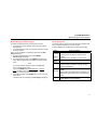
Contacting Fluke
To contact Fluke, call:
1-888-993-5853 in USA
1-800-363-5853 in Canada
+31 402-678-200 in Europe
+81-3-3434-0181 in Japan
+65-738-5655 in Singapore
+1-425-446-5500 from anywhere in the world
Visit Fluke's web site at www.fluke.com.
Register your Meter at http://register.fluke.com.
"Warning" and "Caution" Statements
A "XW Warning" identifies hazardous conditions and actions
that could cause bodily harm or death.
A "Caution" identifies conditions and actions that could damage
the Meter, the equipment under test, or cause permanent loss of
data.
Unsafe Voltage
To alert you to the presence of a potentially hazardous voltage,
when the Meter detects a voltage ≥30 V or a voltage overload
(OL), the Y symbol is displayed.
Test Lead Alert
To remind you to check that the test leads are in the correct
terminals, LEAd is momentarily displayed when you move the
rotary switch to or from the mA or A position.
XW Warning
Attempting to make a measurement with a test lead in
an incorrect terminal might blow a fuse, damage the
Meter, and cause serious personal injury.
1
Models 175, 177 & 179
Users Manual
Battery Saver ("Sleep Mode")
Rotary Switch Positions
The Meter enters the "Sleep mode" and blanks the display if there
is no function change or button press for 20 minutes. To disable
the Sleep mode, hold down the YELLOW button while turning the
Meter on. The Sleep mode is always disabled in the MIN MAX
AVG mode and the AutoHOLD mode.
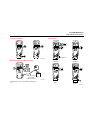
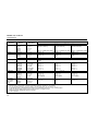
Terminals
.
1
3
FUSED
4
AIK01F.EPS
Item
1
2
3
4
2
Description
Input terminal for AC and DC milliamp measurements to
400 mA and frequency measurements.
Input terminal for AC and DC current measurements to
10 A and frequency measurements.
Input terminal for voltage, continuity, resistance, diode,
capacitance, frequency, and temperature (Model 179
only) measurements.
Common (return) terminal for all measurements.
Measurement Function
K
Hz
L
Hz
AC voltage from 30.0 mV to 1000 V.
Frequency from 2 Hz to 99.99 kHz.
mL
DC mV 0.1 mV to 600 mV.
Temperature
− 40 °C to + 400 °C
T
V
2
Switch
Position
e
E
R
G
FB
mA
Hz
F
BA
Hz
DC voltage 1 mV to 1000 V.
Frequency from 2 Hz to 99.99 kHz.
− 40 °F to + 752 °F
Ohms from 0.1 Ω to 50 MΩ.
Farads from 1 nF to 9999 μF.
Beeper turns on at <25 Ω and turns off at >250 Ω.
Diode test. Displays OL above 2.4 V.
AC mA from 3.00 mA to 400 mA
DC mA from 0.01 mA to 400 mA
Frequency of AC mA 2 Hz to 30 kHz.
AC A from 0.300 A to 10 A
DC A from 0.001 A to 10 A
>10.00 display flashes.
>20 A, OL is displayed.
Frequency of AC A 2 Hz to 30 kHz.
Note: AC voltage and current AC-coupled, true RMS, up to 1 kHz.
True RMS Multimeters
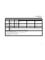
Display
Display
.
5
6
4
7
3
8
2
7
1
9
13
12
No.
1
2
3
4
5
14
Symbol
s
O
K
Y
h
Ah
6
MAX, MIN, AVG
No.
Symbol
7
nμ F, °F, °C
mVA, Mke, kHz
Measurement units.
8
DC, AC
Direct current, alternating current.
9
b
Low battery. Replace battery.
10
11
12
610000mV
Bar graph
Auto Range
All possible ranges.
Analog display.
The Meter selects the range with
the best resolution.
The user selects the range.
Bar graph polarity.
Manual Range
10
11
15
13
±
AIK02F.EPS
14
0L
LEAd
Meaning
Continuity test.
Diode test.
Negative readings.
Unsafe voltage. Voltage ≥ 30 V, or
voltage overload (OL)
Display HOLD is enabled. Display
freezes present reading.
In MIN MAX AVG mode, MIN MAX
AVG recording is interrupted.
AutoHOLD is enabled. Display holds
present reading until it detects new
stable input. Then the Meter beeps
and displays new reading.
MIN MAX AVG enabled.
Maximum, minimum, average or
present reading.
15
bAtt
diSC
EEPr
Err
CAL
Err
OPEn
Meaning
The input out of range.
WTest lead alert. Displayed when
the rotary switch is moved to or
from the mA or A position.
Error Messages
Replace the battery immediately.
In the capacitance function, too much electrical
charge is present on the capacitor being tested.
Invalid EEPROM data. Have Meter serviced.
Invalid calibration data. Calibrate Meter.
Open thermocouple is detected.
3
Models 175, 177 & 179
Users Manual
MIN MAX AVG Recording Mode
Display HOLD and AutoHOLD Modes
The MIN MAX AVG recording mode captures the minimum and
maximum input values, and calculates a running average of all
readings. When a new high or low is detected, the Meter beeps.
XW Warning
To avoid electric shock, do not use the Display HOLD or
AutoHOLD mode to determine if a circuit is live.
Unstable or noisy readings will not be captured.
In the Display HOLD mode, the Meter holds the reading on the
display.
In the AutoHOLD mode, the Meter holds the reading on the display
until it detects a new stable reading. Then the Meter beeps and
displays the new reading.
⇒ Press HOLD to activate Display HOLD. h lights.
⇒ Press HOLD again to activate AutoHOLD. Ah lights.
⇒ Press HOLD again to resume normal operation.
To resume normal operation at any time, press HOLD for 1
second or turn the rotary switch.
Note
For DC functions, accuracy is the specified accuracy of the
measurement function ± 12 counts for changes longer than
350 ms in duration.
For AC functions, accuracy is the specified accuracy of the
measurement function ± 40 counts for changes longer than
900 ms in duration.
To use MIN MAX AVG recording:
⇒ Make sure that the Meter is in the desired measurement
function and range. (Autoranging is disabled in the MIN MAX
AVG mode.)
⇒ Press MIN MAX to activate MIN MAX AVG mode.
and MAX light, and the highest reading detected
since entering MIN MAX AVG is displayed.
⇒ Press MIN MAX to step through the low (MIN), average
(AVG), and present readings.
⇒ To pause MIN MAX AVG recording without erasing stored
values, press HOLD. h is displayed.
To resume MIN MAX AVG recording, press HOLD again.
h turns off.
⇒ To exit and erase stored readings, press MIN MAX for 1
second or turn the rotary switch.
4
YELLOW Button
Press the YELLOW button to select alternate measurement
functions on a rotary switch setting, e.g., to select DC mA, DC A,
Hz, temperature (Model 179 only), capacitance, diode test.
Display Backlight (Model 177 and 179 Only)
Press S to toggle the backlight on and off. The backlight
automatically turns off after 2 minutes.
True RMS Multimeters
Manual Ranging and Autoranging
Manual Ranging and Autoranging
Power-Up Options
The Meter has both Manual range and Autorange modes.
⇒ In the Autorange mode, the Meter selects the range with the
best resolution.
⇒ In the Manual Range mode, you override Autorange and select
the range yourself.
When you turn the Meter on, it defaults to Autorange and Auto
Range is displayed.
1. To enter the Manual Range mode, press RANGE.
Manual Range is displayed.
2. In the Manual Range mode, press RANGE to increment the
range. After the highest range, the Meter wraps to the lowest
range.
To select a Power-Up Option, hold down the button indicated while
turning the Meter from OFF to any switch position.
Power-Up Options are cancelled when the Meter is turned OFF.
Note
You cannot manually change the range in the MIN MAX
AVG, or Display HOLD modes.
If you press RANGE while in MIN MAX AVG, or Display
HOLD, the Meter beeps twice, indicating an invalid
operation, and the range does not change.
3. To exit Manual Range, press RANGE for 1 second or turn the
rotary switch.
The Meter returns to Autorange and Auto Range is displayed.
Button
AutoHOLD
H
M
R
Power-Up Options
K switch position turns on all LCD segments.
L switch position displays the software version
number.
mL switch position displays the model number.
Disables beeper. (bEEP)
Enables "Smoothing" mode. (S---)
Dampens display fluctuations of rapidly changing
inputs by digital filtering.
B
(YELLOW)
S
Disables automatic power-down ("Sleep mode").
(PoFF)
Sleep mode is also disabled while the Meter is in a
MIN MAX AVG Recording mode, or the AutoHOLD
mode.
Disables automatic 2-minute backlight timeout.
(LoFF) (Model 177 and 179 Only)
5
Models 175, 177 & 179
Users Manual
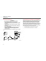
Measuring Resistance
Making Basic Measurements
The figures on the following pages show how to make basic
measurements.
When connecting the test leads to the circuit or device, connect
the common (COM) test lead before connecting the live lead;
when removing the test leads, remove the live lead before
removing the common test lead.
HOLD
MIN MAX
RANGE
XW Warning
To avoid electric shock, injury, or damage to the Meter,
disconnect circuit power and discharge all high-voltage
capacitors before testing resistance, continuity, diodes,
or capacitance.
Measuring AC and DC Voltage
Volts AC
Volts DC
Millivolts DC
AIK04F.EPS
Measuring Capacitance
HOLD
V
MIN MAX
RANGE
HOLD
MIN MAX
RANGE
HOLD
MIN MAX
RANGE
mV
V
HOLD
+
_
+
MIN MAX
RANGE
_
AIK03F.EPS
_
+
+
AIK05F.EPS
6
True RMS Multimeters
Making Basic Measurements
Testing for Continuity
Testing Diodes
Good Diode
HOLD
MIN MAX
HOLD
RANGE
MIN MAX
Good Diode
RANGE
HOLD
MIN MAX
RANGE
HOLD
_
+
MIN MAX
RANGE
_
+
Single Beep
AIK06F.EPS
Measuring Temperature (Model 179 Only)
HOLD
MIN MAX
Forward Bias
Reverse Bias
Bad Diode
Bad Diode
RANGE
HOLD
MIN MAX
RANGE
HOLD
MIN MAX
RANGE
RANGE
80BK-A Integrated
Type K DMM
Temperature Probe
Vent
or
Pipe
CAT
_
+
_
+
AIK10F.EPS
XW Warning: Do not connect 80BK-A to live circuits.
and
Open
Shorted
AIK07F.EPS
7
Models 175, 177 & 179
Users Manual
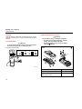
Measuring AC or DC Current
XW Warning
To avoid personal injury or damage to the Meter:
• Never attempt to make an in-circuit current
measurement when the open-circuit potential to earth
is >1000 V.
• Check the Meter's fuses before testing. (See “Testing
the Fuses”.)
• Use the proper terminals, switch position, and range
for your measurement.
• Never place the probes in parallel with a circuit or
component when the leads are plugged into the
current terminals.
Turn power OFF, break circuit, insert Meter in series, turn power
on.
DC
HOLD
MIN MAX
RANGE
mA
A
+
CAT
CAT
+
AIK08F.EPS
8
Understanding AC Zero Input Behavior of True RMS Meters
Unlike averaging meters, which can accurately measure only pure
sinewaves, True RMS meters accurately measure distorted
waveforms. Calculating True RMS converters require a certain
level of input voltage to make a measurement. This is why AC
voltage and current ranges are specified from 5% of range to
100% of range. Non-zero digits that are displayed on a True RMS
meter when the test leads are open or are shorted are normal.
They do not affect the specified AC accuracy above 5% of range.
Unspecified input levels on the lowest ranges are:
•
AC voltage: below 5% of 600 mV AC, or 30 mV AC
•
AC current: below 5% of 60 mA AC, or 3 mA AC
True RMS Multimeters
Using the Bar Graph
Measuring Frequency
Using the Bar Graph
XW Warning
To avoid electrical shock, disregard the bar graph for
frequencies > 1 kHz. If the frequency of the measured
signal is > 1 kHz, the bar graph is unspecified.
The Meter measures the frequency of a signal. The trigger level is
0 V, 0 A AC for all ranges.
The bar graph is like the needle on an analog Meter. It has an
overload indicator (>) to the right and a polarity indicator (±) to the
left.
Because the bar graph updates about 40 times per second, which
is 10 times faster than the digital display, the bar graph is useful
for making peak and null adjustments and for observing rapidly
changing inputs.
The bar graph is disabled when measuring capacitance or
temperature. In frequency, the bar graph accurately indicates the
voltage or current up to 1 kHz.
The number of lit segments indicates the measured value and is
relative to the full-scale value of the selected range.
In the 60 V range, for example (see below), the major divisions on
the scale represent 0, 15, 30, 45, and 60 V. An input of −30 V
lights the negative sign and the segments up to the middle of the
scale.
AC/DC Voltage Frequency
AC Current Frequency
x2
HOLD
MIN MAX
RANGE
Hz
Hz
HOLD
V
MIN MAX
RANGE
mA
V
A
+
+
AIK09F.EPS
⇒
⇒
⇒
AIK11F.EPS
To exit frequency, press YELLOW button or turn the rotary
switch.
In frequency, the bar graph shows the AC/DC voltage or AC
current accurately up to 1 kHz.
Select progressively lower ranges using manual ranging for a
stable reading.
9
Models 175, 177 & 179
Users Manual
Cleaning
Replacing the Battery and Fuses
Wipe the case with a damp cloth and mild detergent. Do not use
abrasives or solvents. Dirt or moisture in the terminals can affect
readings.
Testing the Fuses
XW Warning
To avoid electrical shock or injury, remove the test leads
and any input signals before replacing the fuse.
Test fuses as shown below.
440 mA
<12 Ω
HOLD
MIN MAX
RANGE
XW Warning
To avoid shock, injury, or damage to the Meter:
• Use ONLY fuses with the amperage, interrupt,
voltage, and speed ratings specified.
• Replace the battery as soon as the low battery
indicator (b) appears.
b
I
11 A
OK
OK
<.5 Ω
OK
OK
B1
F1
F2
V
AIK12F.EPS
AIK13F.EPS
F1 Fuse, 440 mA, 1000 V, FAST
F2 Fuse, 11 A, 1000 V, FAST
Fluke PN 803293
B1 Battery, 9 V Alkaline
Fluke PN 614487
NEDA 1604 / 1604A
10
Fluke PN 943121
True RMS Multimeters
Specifications
Specifications
Accuracy is specified for 1 yr after calibration, at operating temperatures of 18 °C to 28 °C, with relative humidity at 0 % to 90 %. Accuracy
specifications take the form of: ± ( [ % of Reading ] + [ Counts ] )
Maximum voltage between any terminal and earth ground: 1000 V DC or AC RMS
Surge Protection:
8 kV peak per IEC 61010
W Fuse for mA inputs:
440 mA, 1000 V FAST Fuse
W Fuse for A input:
11 A, 1000 V FAST Fuse
Display:
Digital: 6000 counts, updates 4/sec
Bar Graph:
33 segments;
Updates 40/sec
Frequency:
10,000 counts
Capacitance: 1,000 counts
Altitude:
Operating: 2000 m; Storage: 12,000 m
Temperature:
Operating: −10 °C to +50 °C;
Storage: −40 °C to +60 °C
Temperature coefficient: 0.1 X (specified accuracy / °C
(< 18 °C or > 28 °C)
Electromagnetic
In an RF field of 3 V/M, accuracy = specified accuracy except in temperature: specified accuracy ± 5 °C (9 °F)
Compatibility
(EN 61326-1:1997):
Relative Humidity:
Maximum Noncondensing
90 % to 35 °C
75 % to 40 °C
45 % to 50 °C
Battery Life:
Alkaline: 400 hrs typical
Size (H x W x L):
4.3 cm x 9 cm x 18.5 cm
Weight:
420 g
Safety Compliances:
ANSI/ISA S82.02.01, CSA C22.2-1010.1, IEC 61010 to 1000 V Measurement Category III, 600 V Measurement
Category IV
Certifications:
CSA, TÜV (EN61010), UL, P, ;, VDE
11
Models 175, 177 & 179
Users Manual
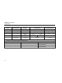
Function
AC Volts 2, 3
DC mV
DC Volts
Continuity
Ohms
Diode test
Capacitance
AC Amps 5
(True RMS)
(45 Hz to 1
kHz)
1.
2.
3.
4.
5.
6.
7.
12
Range
1
Resolution
600.0 mV
6.000 V
60.00 V
600.0 V
1000 V
600.0 mV
6.000 V
60.00 V
600.0 V
1000 V
600 Ω
0.1 mV
0.001 V
0.01 V
0.1 V
1V
0.1 mV
0.001 V
0.01 V
0.1 V
1V
1Ω
600.0 Ω
6.000 kΩ
60.00 kΩ
600.0 kΩ
6.000 MΩ
50.00 MΩ
2.400 V
1000 nF
10.00 μF
100.0 μF
9999 μF 4
60.00 mA
400.0 mA6
6.000 A
10.00 A7
0.1 Ω
0.001 kΩ
0.01 kΩ
0.1 kΩ
0.001 MΩ
0.01 MΩ
0.001 V
1 nF
0.01 μF
0.1 μF
1 μF
0.01 mA
0.1 mA
0.001 A
0.01 A
Model 175
1.0 % + 3
(45 Hz to 500 Hz)
Accuracy ±( [ % of Reading ] + [ Counts ] )
Model 177
Model 179
1.0 % + 3
1.0 % + 3
(45 Hz to 500 Hz)
(45 Hz to 500 Hz)
2.0 % + 3 (500 Hz to 1 kHz)
0.15 % + 2
2.0 % + 3 (500 Hz to 1 kHz)
0.09 % + 2
2.0 % + 3 (500 Hz to 1 kHz)
0.09 % + 2
0.15 % + 2
0.09 % + 2
0.09 % + 2
0.15 % + 2
0.15 % + 2
0.15 % + 2
Meter beeps at < 25 Ω, beeper turns off at > 250 Ω; detects opens or shorts of 250 μs or
longer.
0.9 % + 2
0.9 % + 2
0.9 % + 2
0.9 % + 1
0.9 % + 1
0.9 % + 1
0.9 % + 1
0.9 % + 1
0.9 % + 1
0.9 % + 1
0.9 % + 1
0.9 % + 1
0.9 % + 1
0.9 % + 1
0.9 % + 1
1.5 % + 3
1.5 % + 3
1.5 % + 3
1%+2
1.2 % + 2
1.2 % + 2
1.2 % + 2
1.2 % + 2
1.2 % + 2
1.2 % + 2
1.2 % + 2
1.2 % + 2
1.2 % + 2
10 % typical
10 % typical
10 % typical
1.5 % + 3
1.5 % + 3
All AC voltage and AC current ranges are specified from 5 % of range to 100 % of range.
Crest factor of ≤ 3 at full scale up to 500 V, decreasing linearly to crest factor ≤ 1.5 at 1000 V.
For non-sinusoidal waveforms, add -(2% reading + 2% full scale) typical, for crest factors up to 3.
In the 9999 μF range for measurements to 1000 μF, the measurement accuracy is 1.2 % + 2 for all models.
Amps input burden voltage (typical): 400 mA input 2 mV/mA, 10 A input 37 mV/A.
400.0 mA accuracy specified up to 600 mA overload.
> 10A unspecified.
1.5 % + 3
True RMS Multimeters
Specifications
Function
DC Amps4
Hz
(AC- or DCcoupled, V or
A 2, 3 input )
Temperature
MIN MAX AVG
1.
2.
3.
4.
5.
6.
7.
Range
60.00 mA
400.0 mA6
6.000 A
10.00 A7
99.99 Hz
999.9 Hz
9.999 kHz
99.99 kHz
1
Resolution
0.01 mA
0.1 mA
0.001 A
0.01 A
0.01 Hz
0.1 Hz
0.001 kHz
0.01 kHz
Model 175
Accuracy ±( [ % of Reading ] + [ Counts ] )
Model 177
Model 179
1.0 % + 3
1.0 % + 3
1.0 % + 3
0.1 % + 1
0.1 % + 1
0.1 % + 1
-40 °C to +400 °C
0.1 °C
1 % + 105
NA
NA
-40 °F to +752 °F
0.1 °F
1 % + 185
For DC functions, accuracy is the specified accuracy of the measurement function ±12 counts for changes longer than 350 ms in
duration.
For AC functions, accuracy is the specified accuracy of the measurement function ±40 counts for changes longer than 900 ms in
duration.
All AC voltage and AC current ranges are specified from 5 % of range to 100 % of range.
Frequency is specified from 2 Hz to 99.99 kHz in Volts and from 2 Hz to 30 kHz in Amps.
Below 2 Hz, the display shows zero Hz.
Amps input burden voltage (typical): 400 mA input 2 mV/A, 10 A input 37 mV/A.
Does not include error of the thermocouple probe.
400.0 mA accuracy specified up to 600 mA overload.
> 10A unspecified.
13
Models 175, 177 & 179
Users Manual
Common Mode Rejection Ratio
(1 kΩ Unbalanced)
Overload Protection 1
Input Impedance
(Nominal)
Volts AC
1000 V RMS
> 10 MΩ < 100 pF
> 60 dB @ DC, 50 Hz or 60 Hz
Volts DC
1000 V RMS
> 10 MΩ < 100 pF
>120 dB @ DC, 50 Hz or 60 Hz
> 60 dB @ 50 Hz or 60 Hz
mV/T
1000 V RMS
> 10 MΩ < 100 pF
>120 dB @ DC, 50 Hz or 60 Hz
> 60 dB @ 50 Hz or 60 Hz
Open Circuit Test
Voltage
Full Scale Voltage To:
600 kΩ
50 MΩ
Short Circuit Current
Function
2
2
Ohms/Capacitance
1000 V RMS
Continuity/Diode
test
2
1000 V RMS
< 8.0 V DC
< 8.0 V DC
< 4.6 V DC
< 1.1 mA
2.4 V DC
< 1.1 mA
7
1.
10 V-Hz maximum.
2.
For circuits < 0.3 A short circuit. 660 V for high energy circuits.
Function
mA
A
14
< 660 mV DC
Normal Mode Rejection
Overload Protection
Overload
Fused, 44/100 A, 1000 V FAST Fuse
600 mA overload for 2 minutes maximum, 10
minutes rest minimum
Fused, 11 A, 1000 V FAST Fuse
20 A overload for 30 seconds maximum, 10
minutes rest minimum