1
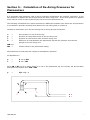
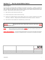
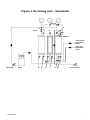
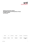
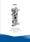
De-Airing Unit With Manual Pumps
User Manual
Man 097
5.0.1
04/08/2014
C.Spalton
Andy Small
Chris Rasmussen
Manual No.
Revision
Date
Originator
Checked
Authorised for
Issue
User Manual
1
Contents
Section 1 :
General Information ...................................................................................... 3
Section 2 :
Installation Of The De-Airing Unit ................................................................. 4
Section 3 :
Preparation And Setting Up ........................................................................... 5
Section 4 :
Operating And Recharging............................................................................. 6
Section 5 :
Calculation Of De-Airing Pressures For Piezometers ...................................... 7
Section 6 :
Calculating De-Airing Water Volumes .......................................................... 10
Section 7 :
The De-Aired Water Boiler ........................................................................... 11
Figure 1 De-Airing Unit - Schematic ................................................................................ 12
Figure 2 De-Aired Water Boiler ....................................................................................... 13
User Manual
2
Section 1 : General Information
Refer to Figure 1
The de-airing unit consists essentially of pressure, supply and return tanks (A, B and C) and gauges
to measure water pressure and vacuum during circulation of de-aired water through Hydraulic
Piezometers. These components are mounted on a frame complete with valves and connecting pipe
work. Foot pressure and vacuum pumps are used to operate the equipment. Pressure is applied to
the de-aired water in supply tank B by forcing water from the pressure tank A into the bladder in B.
Water from the supply tank is then circulated through the piezometer tubes back to the return tank
C. The volume changes measured in both the pressure and return tanks A and C indicate the
quantity of water circulated through the system. The object is to completely replace the water in
the piezometer tubes with freshly de-aired water.
The equipment is fully tested before despatch. However, it is possible that movements during
transit may disturb the cylinders, pipework or valves sufficiently to cause small leaks when the
equipment is operated. If any leaks are observed during operation they should be eliminated by
gently tightening the appropriate component.
NEVER modify the arrangement without the full written approval of itmsoil as unauthorised
modifications may bypass the safety system.
It is advisable to drain water from the equipment during cold weather to prevent damage to the
cylinders due to freezing.
WARNING
If an anti-freeze solution is used, the system must be flushed with clean water to
prevent the bladder from perishing over time.
WARNING
External high pressure gas cylinders must not be connected to this de-airing unit.
User Manual
3
Section 2 : Installation of the De-Airing Unit
The unit is mounted vertically and level on anchor bolts fixed to the instrument house wall, at a
convenient height for the operation of all the valves, or stood on a level working surface. Connect
the manifolds on the piezometer terminal panels to the busbar tee-piece connections on the deairing unit. Blank-off the other side of the tee-pieces with the stop-end fittings provided.
WARNING
External high pressure gas cylinders must not be connected to this de-airing unit.
User Manual
4
Section 3 : Preparation And Setting Up
The valves must be operated in the order given, commencing with all the valves in the closed
position. Please refer to figure 1 of this manual for valve positions.
3.1
Attach the vacuum pump with the black hose supplied to valve F. Open valves F, G and N
and apply vacuum until the bladder in cylinder B is completely evacuated, on solid cylinders
this is indicated by an increase in resistance when operating the vacuum pump.
Close valves F, G and N.
3.2
Immerse one end of the red rubber tube into a container of clean water and attach the other
end to valve K. Open valves K and F and operate the vacuum pump drawing the water into
cylinder A. When the tank is 90% full, close valves K and F. Remove the vacuum pump from
valve F, open valve F to release the vacuum, and then close.
3.3
Prepare de-aired water in the de-aired water boiler, allowing it to cool. (See Section 5 and
Figure 1.) Connect valve S on the boiler to valve M using the red rubber hose. Attach the
vacuum pump to valve I, open valves I and M and release the vacuum from the boiler by
opening valve V on the boiler. Open valve S on the boiler and by operating the vacuum pump
slowly draw the de-aired water into cylinder C until it is 90% full. Close all valves.
3.4
Remove the vacuum pump and open valve I to release the vacuum. Open valves G and L,
attach the vacuum pump to valve G and draw the de-aired water from cylinder C into cylinder
B by operating the vacuum pump until cylinder C is only 10% full. Close all valves. To fill
cylinder B completely it is necessary to repeat the operation but this time only half filling
cylinder C with de-aired water. When cylinder B is almost full close all valves. Remove the
vacuum hose from valve G, open valve G to release the vacuum, and then close.
3.5
Attach the pressure pump to valve E, open valve E and N then operate the pressure pump to
bring the pressure in cylinder A to approximately 10mH20. Gently open valve G thereby
inflating the bladder, displacing the de-aired water in cylinder B and forcing out any
remaining air. Any bubbles of air that cling to the rubber bladder and walls of the cylinder B
should be dislodged by slapping the sides of the cylinder until they rise and accumulate under
valve G. They are then removed by momentarily opening valve G.
It is important that cylinder B is completely filled with de-aired water and all air excluded. Close all
valves and release pressure from cylinder A by removing the pressure pump and opening valve F.
3.6
Repeat 3.3 to refill cylinder C.
3.7
Attach the vacuum pump to valve F. Open valves F, L, N and I and apply vacuum to cylinder
A. Water is drawn from inside the bladder in cylinder B to cylinder A, thus drawing de-aired
water from cylinder C into cylinder B. When the bladder is fully deflated the cylinder A will
again be 90% full of water. Close valves F, L, N and I. Remove the vacuum pump from valve
F. Open valve F to release vacuum in cylinder A.
3.8 Open valves I and M and drain any remaining water back to the de-aired water boiler. Close
all valves. The de-airing unit is now fully charged with de-aired water and ready for operation.
WARNING
If an anti-freeze solution is used, the system must be flushed with clean water to
prevent the bladder from perishing over time.
User Manual
5
Section 4 : Operating and Recharging
The valves must be operated in the order given, commencing with all valves in the closed position.
4.1
Calculate the optimum de-airing pressures (see Section 5), attach the pressure pump to Valve
E and the vacuum pump to valve I. Open valve E. Operate the pressure pump until the
desired pressure is reached in cylinder A, as indicated by the pressure gauge. If a vacuum is
required on the return cylinder C, open valve I and operate the foot vacuum pump until the
desired vacuum is reached as indicated by the vacuum gauge.
4.2
Open valves N, P and V and appropriate valves on the terminal panel for the selected
piezometer to be de-aired, and circulate de-aired water at the calculated pressure through the
piezometer tubing, measuring the amount sent on the graduated scale of the pressure
cylinder A.
Circulate water until no more air bubbles are seen to be returning through the water in cylinder C
finally checking that the volume of water returning to cylinder C corresponds to the volume leaving
the de-airing unit. (Volume from cylinder A).
As the de-airing operation proceeds the pressure and vacuum will drop slowly and it will be
necessary from time to time to re-adjust these to the original calculated values by operating the
foot pumps.
During operation of the unit the bladder in cylinder B should not be allowed to distend to more than
90% of the volume of the cylinder. (Cylinder A level is not lower than 10% full) At this point it is
necessary to recharge with de-aired water as follows:
4.3
Close all valves.
4.4
Disconnect the pressure and vacuum pumps. Open valves F and I to release the
pressure and vacuum from the cylinders then close the valves.
4.5
Drain water from cylinder C through valve M. Do not return it to the de-airing water boiler.
4.6
Connect valve S on the boiler to valve M using the red rubber hose. Attach the vacuum pump
to valve I, open valves I and M and release the vacuum from the boiler by opening valve V on
the boiler. Open valve S on the boiler and by operating the vacuum pump slowly draw the
de-aired water into cylinder C until it is 90% full.Close all valves.
4.7
Attach the vacuum pump to valve F. Open valves F, N, L and I and apply vacuum to cylinder
A. Water is drawn from inside the bladder in cylinder B to cylinder A, thus drawing de-aired
water from cylinder C into cylinder B. When the bladder is fully deflated the cylinder A will
again be 90% full of water. Close valves F, N, L and I. Remove the vacuum pump from valve
F. Open valve F to release vacuum in cylinder A.
4.8
Open valves I and M and drain any remaining water back into the de-airing water boiler.
Close all valves. Attach the pressure pump to valve E and the vacuum pump to valve I. The
unit is now fully charged with de-aired water and ready for operation
User Manual
6
Section 5 : Calculation of De-Airing Pressures for
Piezometers
It is important that pressures used to de-air hydraulic piezometers are carefully controlled. If too
little pressure is applied the de-airing process will take a long time. If too much pressure is applied
there may be a risk of hydro fracturing the soil around the piezometer tip.
The following calculations are used to determine a balanced condition from which the send pressure
is increased to generate a steady flow observed in the tubing and in cylinder A.
Consider a piezometer tip in the soil during the de-airing process as follows:u
=
pore pressure in the fill at the tip.
p
=
pressure on the pressure side of the de-airing unit.
v
=
pressure on the vacuum side of the de-airing unit.
h
=
difference in head between the piezometer tip and the pressure and vacuum
gauges on the de-airing unit.
fAB and
fBC =
friction losses in the piezometer tubing.
All pressures are measured with respect to atmospheric pressure.
For Equilibrium:p
=
h + u + fAB
v
=
h + u - fBC
Since AB = BC and if no water flows in or out of the piezometer tip, the velocity will be the same
throughout the system then fAB = fBC
p
=
2(h + u) - v
h
p
v
User Manual
7
In a piezometer installation h is known, v is maintained at a known value, and u for each
piezometer tip is estimated using previous pore pressure readings. In this way p is calculated for
each piezometer and de-airing carried out at the appropriate pressure.
If the piezometer lies below the readout point, the term h, the difference in head between the
piezometer tip and pressure and vacuum gauges on the de-airing unit, changes sign and becomes
negative.
When a piezometer tip has accumulated a
pressure to drive water at least as far as the
friction loss in the return tube carrying air is
drawn in through the piezometer tip from the
User Manual
lot of air, care should be taken to apply sufficient
tip before applying a vacuum to the other tube, since
much less than in one carrying water, and air will be
surrounding fill.
8
Example 2
p
v
PIEZOMETRIC LEVEL
7m(h)
4m
U=4mH20
TIP
Where
for
for
for
User Manual
p
=
2 (h + u) - v
p
=
2 (-7 +4) - v
p
=
-6 - v
v
=
0
p
=
-6 mH20
v
=
-5 mH20
p
=
-1 mH20
v
=
-10 mH20
p
=
4 mH20
9
Section 6 : Calculating De-Airing Water Volumes
It is important to determine the volume of de-airing water to be circulated through each hydraulic
piezometer.
The amount of de-aired water required depends on the length of piezometer tubing between the
installed piezometer tip and the de-airing unit.
Tubing with 2.8mm or 3.8mm internal diameter is usually used.
6.1
Calculate from installation layout drawings or physically measure the distance in metres from
the installed piezometer tip to the de-airing unit.
6.2
Multiply installed length by the appropriate cross sectional area (0.013 for tubing with 2.8mm
internal diameter or 0.023 for tubing with 3.8mm internal diameter) to give de-airing water
volume in litres.
Add at least 10% to the calculated volume to allow for tubing snaking etc.
User Manual
10
Section 7 : The De-Aired Water Boiler
Refer to Figure 2
Up to 50 litres of de-aired water is prepared in the boiler at one filling. A heater coil heats the
water to boiling thus expelling any air or gases in solution. By sealing the boiler and allowing it to
cool, the steam and water vapour above the water condense thus creating a partial vacuum inside
the boiler. This prevents further solution of air or gases.
7.1
Open valves V and S. Remove the filler cap.
7.2
Fill with clean water to within 100mm of the top.
7.3
Connect to a suitable electricity mains supply (either 110V or 230V as indicated on the heater
coil cover). Switch on. Bring to the boil and allow to boil for fifteen minutes. Switch off.
7.4
Close valves V and S replace the central filler cap. Allow to cool.
WARNING
- Although the filler cap is fitted with a pressure relief valve, NEVER
boil with the filler cap on.
NOTE
- With a partial vacuum inside the boiler, NEVER open valve S before opening valve V,
as this will draw air into the de-aired water.
SAFETY REQUIREMENTS - The 4 psi Pressure Relief Valve in the centre of the filler cap must be
checked by a competent person, at intervals not exceeding 12 months.
Bell Lane, Uckfield, East Sussex
t: +44 (0) 1825 765044
e: [email protected]
TN22 1QL United Kingdom
f: +44 (0) 1825 744398
w: www.itmsoil.com
Soil Instruments Ltd. Registered in England. Number: 07960087. Registered Office: 5th Floor, 24 Old Bond Street, London, W1S 4AW
User Manual
11
Figure 1 De-Airing Unit - Schematic
N.R.VV
S
R
H
E
P.R.V.
F
G
I
PPP.R.V
Tubing from
Piezometer
Panel
Tubing to
Piezometer
Panel
Footpump
User Manual
Boiler
K
N
P
L
V M
Vacuum Pump
12
Figure 2 De-Aired Water Boiler
Valve S
Filler Cap
Vacuum
Gauge
Valve
V
Heater
Coil
Cable to
Electricity Supply
User Manual
13