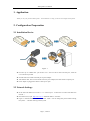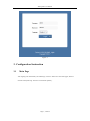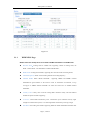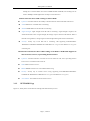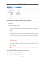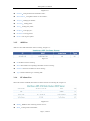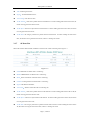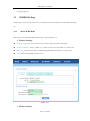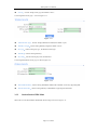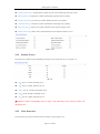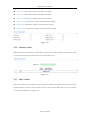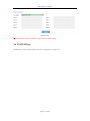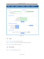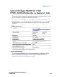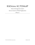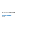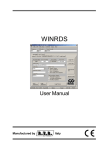
1
WIS-Q2300 User Manual WIS-Q2300 User Manual V1.0 Page 1 , Total 26 WIS-Q2300 User Manual 1. Application Thank you for your purchase WIS-Q2300。This handbook is to help you know and configure WIS-Q2300. 2. Configuration Preparation 2.1 Installation Device Figure 1 Press the clip of 2.4GHz CPE,pull out the cover,stick one end of cable into ETH port; Slide the cover until the clip locked. Stick the other end of cable into POE port of power adapter. Take another cable, stick one end of cable into LAN port of adapter, the other end into computer port. Power adapter is plugged into outlet to ensure power open. 2.2 Network Settings Set PC and set IP address as 192.168.1.x(x is 1-254 except 2,to make sure no conflict with other IP of network.) Run Web browser, input http://192.168.1.2(default IP address)and enter。 Figure 2,Default username:admin,Password:admin(You can change this password after entering the system),and then click Login to the system. Page 2 , Total 26 WIS-Q2300 User Manual Figure 2 3. Configuration Instruction 3.1 Main Page After logining enter automatically into Main Page, as shown. Status has 3 status label pages, Wireless、 Network and System Page. The below is introduced separately. Page 3 , Total 26 WIS-Q2300 User Manual Figure 3-1 3.1.1 WIRELESS Page Radio status box mainly shows work mode and RF information of 2.4GHz CPE. Wireless mode:working mode of 2.4GHz CPE, supporting 4 kinds of working mode, AP Mode、Station Mode、AP WDS Mode and Station WDS Mode; Radio mode: working mode of Radio, supporting 802.11a/an two kinds of working modes; Channel/Frequency: Radio current working channel and working frequency; Channel Width: Radio channel bandwidth , supporting 20MHz and 40MHz. Channel bandwidth has great influence to the wireless. Under no interference environment, average throughput of 40MHz channel bandwidth can reach more than twice of 20MHz channel bandwidth; Country Code: country code of current working Radio. Different country code has different channel and power for Radio supporting; Tx Power: current Radio transmission power. Transmission power influences directly signal strength of communication system, so we should guarantee transmission power big enough; Max Rate: max sending rate of Radio supporting. Different channel bandwidth could affect max Page 4 , Total 26 WIS-Q2300 User Manual sending rate. If AP and Station can reach to 40MHz channel bandwidth, max sending rate can reach to 300Mbps, and throughout rate can improve more than twice. Station status box shows CPE working as Station Mode. Up/Down: UP means CPE has successfully connected with AP. Down means that CPE has not SSID: SSID name of AP that CPE is connecting; BSSID: BSSID address of AP that CPE is connecting ; Signal Strength: signal strength of AP that CPE is connecting;Signal strength is negative, the smaller the absolute value of signal strength, the stronger it proves between CPE and AP. When it transmits in long distance, stronger signal can ensure higher thorough for wireless transmission. Security: security way of AP that CPE is connecting, CPE supporting None/WEP/WPATKIP/WPA-CCMP/WPA2-TKIP/WPA2-CCMP/WPA mix encryption and WPA2 mix encryption connecting AP。 Wireless1/2/3/4 status box shows CPE working as AP Mode. 2.4GHz CPE supports at most 4 wireless services, representing Wireless1/2/3/4. Up/Down: UP means interface of wireless service has started to work, and is providing wireless access services. And down means it has not. SSID: SSID of wireless service; BSSID: BSSID of wireless service broadcast Beacon using Security: security way of wireless service using, supporting None/WEP/WPA-TKIP/WPACCMP/WPA2-TKIP/WPA2-CCMP/WPA mix encryption and WPA2 mix encryption; 3.1.2 Asso number: asso number of current wireless service. NETWORK Page Figure 3-2, mainly shows current network working mode and network parameter. Page 5 , Total 26 WIS-Q2300 User Manual Figure 3-2 Network Mode of Network Role status box shows current network mode. Network Mode: device supports 3 kinds of Network Modes, namely Bridge Mode、SOHO Router Mode and WISP Mode. We will have a brief introduction to those: 1. Bridge Mode: Bridge Mode is typical 2-layer network mode. CPE ETH port and wireless interface are working at 2-layer network mode, no independent IP address. For the whole CPE only Bridge port has IP address. 2. SOHO Router Mode: This mode is typical network mode of home wireless router. The ETH port is worked as WAN interface, connecting outer net by ETH port, like Internet or enterprise network. This device connects with public network supporting three ways: static IP address, DHCP dynamic IP address and PPPoE. ※Attention: Only when CPE works as AP Mode and AP WDS Mode, network mode can be set as SOHO Router Mode. 3. WISP Mode: This mode is opposite to SOHO Router. It uses wireless interface as WAN to connect public network and ETH port as 2-layer access port. For this mode we can think CPE as a large wireless network card. ※Attention: Only when CPE works as Station Mode or Station WDS Mode,network mode can be set as WISP Mode. Network Settings status box shows some basic network parameter. Bridge IP Address: IP address of Bridge interface; Net mask: net mask of bridge interface IP address; Page 6 , Total 26 WIS-Q2300 User Manual Bridge Mac: MAC address of bridge interface; Gateway: gateway IP Address of bridge interface; Primary DNS IP: primary DNS address of bridge interface; Secondary DNS IP: secondary DNS address of bridge interface; 3.1.3 SYSTEM Page This page mainly shows version, device name and so on, as shown Figure 3-3. Figure 3-3 3.1.4 Device Name: device name; Serial Number: device serial NO.; Software Version: current software version; Language: current web language; Time zone: current time zone; Current time: current time; Username: username when logining; Interfaces List Interfaces list counts send-receive info of all interfaces, as shown Figure 3-4. Page 7 , Total 26 WIS-Q2300 User Manual Figure 3-4 Interface:listing all interfaces and interface name; MAC Address:listing MAC address of all interfaces; Tx Bytes:sending bytes number; Tx Packet:sending packet ; Tx Err:sending error packet ; Rx Bytes:receiving bytes ; Rx Packet: receiving packet; Rx Err: receiving error packet. 3.1.5 ARP List ARP List counts ARP information of device learning, as Figure 3-5. Figure 3-5 IP: IP address of device learning; MAC: MAC address corresponding to IP address of device learning; Interface: interface to IP address of device learning; Type: interface hardware type of learning ARP. 3.1.6 STA Stats List When CPE works as AP Mode, STA Status List shows STA info of connecting AP, as Figure 3-6 Figure 3-6 BSSID:BSSID of STA connecting wireless services; Mode:working mode of STA Radio; Page 8 , Total 26 WIS-Q2300 User Manual AID: connecting ID of STA; Signal:AP detected RSSI of STA; Assoc Time:time online of STA; Tx/Rx Packets:send-receive packets between AP and STA. Tx means sending packets from AP to STA, Rx means receiving packets from STA to AP; Tx/Rx Bytes: send-receive bytes between AP and STA. Tx means sending bytes from AP to STA, Rx means receiving bytes from STA to AP; Tx/Rx Rate: rate using by send-receive packets between AP and STA. Tx means senidng rate from AP to STA, Rx means receving rate from STA to AP, in fact it is sending rate of STA. 3.1.7 AP Stats List When CPE works as Station Mode, AP Status List shows info of CPE connecting AP, as Figure 3-7 Figure 3-7 SSID: SSID name of AP that CPE is connecting; BSSID: BSSID address of AP that CPE is connecting; Mode:Radio work mode of AP that CPE is connecting; Channel: working channel of AP that CPE is connecting; Signal: CPE detected AP RSSI; Assoc Time:duration online after CPE is connecting AP; Tx/Rx Packets:send-receive packets between CPE and AP. Tx means sending packets from CPE to AP, Rx means receiving packets from AP to CPE; Tx/Rx Bytes: send-receive bytes between CPE and AP. Tx means sending bytes from CPE to AP, Rx means receiving bytes from AP to CPE ; Tx/Rx Rate: rate using by send-receive packets between CPE and AP. Tx means senidng rate from CPE to AP, Rx means receving rate from AP to CPE, in fact it is sending rate of AP. Page 9 , Total 26 WIS-Q2300 User Manual 3.1.8 Routes List Routes list shows current routing relationship of device, as Figure 3-8. Figure 3-8 Destination: destination address and mask; Gateway:next address against destination address, that is gateway address. Flags:network type of this routing info; Interface:interface of this routing info. 3.1.9 PPPoE Information List PPPoE information list shows connecting state of current PPoE, as Figure 3-9. Figure 3-9 Server Name:server name of PPPoE server; Connection Time:time online of PPPoE connection; Local IP Address:local IP address of PPPoE client; Remote IP Address:remote IP address of PPPoE server; Primary DNS IP:primary DNS address of PPPoE client; Secondary DNS IP:secondary DNS address of PPPoE client ; TX Packets:CPE sending packets by PPP interface; RX Packets:CPE receiving packets by PPP interface; TX Bytes: CPE sending bytes by PPP interface; Page 10 , Total 26 WIS-Q2300 User Manual RX Bytes: CPE receiving bytes by PPP interface. 3.1.10 DHCP Server List DHCP Server List shows status of assigning IP address when CPE is DHCP Server, as Figure 3-10。 Figure 3-10 MAC Address:MAC address of DHCP Client; IP Address:IP address of DHCP Client; Remaining Lease: remaining lease to this IP address of DHCP Server; Hostname:hostname of DHCP Client. 3.2 Radio Page Radio Page is mainly used for setting WLAN R/F parameter, as Figure 3-11. Figure 3-11 Page 11 , Total 26 WIS-Q2300 User Manual 3.2.1 Basic Wireless Settings Wireless Mode:used for working mode of WLAN, 2.4GHz CPE supporting AP Mode, Station Mode, AP WDS Mode and Station WDS Mode, the default is Station Mode. Because settings of those 4 modes have little impact to parameter setting of whole Radio,we will not introduce parameter setting of Radio for 4 modes. Country code:used for setting country code of Radio, the default is China; IEEE 802.11 Mode:used for setting working mode of Radio, the default is 802.11n; Channel Width:used for setting occupied bandwidth of channel, the default is 20MHz Mode; Channel:used for setting working channel of Radio, the default is auto channel; Tx Power:used for setting transmission power of Radio, the default is 24dBm; ※Attention:Transmission power can influence signal strength of wirelss communication. when it transmits in long distance, pls properly increase transmit power to ensure stronger singal. And when testing indoor, pls properly decrease transimission power in order to prevent signal saturation for higher signal strength. Max TX Rate:used for setting packets sending rate of Radio. 2.4GHz CPE is 2X2 device, so max support is MCS=15 and default setting. 3.2.2 Advanced Wireless Settings RTS Threshold:used for setting RTS/CTS threshold, the default is off state; ※Attention:RTS/CTS is mainly to prevent hidden node disturbing. But if RTS/CTS threshold is set much smaller, it may obviously reduce throughtput rate of wireless communication. Fragmentation Threshold:used for setting fragmentation threshold, the default is off state; Distance:used for setting transmission distance between AP and STA, so that system can choose proper ACK _timeout, the default is 3Km. When it is transmitting in long distance, proper adjusting Distance can improve throughtput rate. Aggr Enable:used for setting “enable” and “to enable”sending function of A-MPDU, the default is enable state; Aggr limit Enable:used for setting sending limit function of A-MPDU, the default is enable state, the max aggr packet of the default is 64 units, the max aggr length is 60000 bytes. As long as one conditon meets, it Page 12 , Total 26 WIS-Q2300 User Manual will trigger aggr limit. 3.3 WIRELESS Page Wireless Page is used for setting wireless service of AP Mode or relevant parameters for Station Mode connecting AP . 3.3.1 AP/AP WDS Mode When CPE is set as AP/AP WDS Mode, Wireless Page is shown as Figure 3-12. 1. Wireless Settings Wireless1/2/3/4:device can set 4 wireless service at most, separately 4 labels to distinguish; Wireless Availability:used for “enable” or “to enable” wireless service, the default is “to enable” state; Hide SSID:used for “enable” and “to enable” hiding SSID function, the default is “to enable” state; SSID: used for entering SSID of wireless service. Figure 3-12 2. Wireless Security Page 13 , Total 26 WIS-Q2300 User Manual Security:used for setting security type, the default is None.; If choosing WEP security type,as shown Figure 3-13. Figure 3-13 Authentication Type:used for setting authentication method, the default is open; WEP Key Length:used for setting WEP key length, the default is 64 bit; Key Type:used for setting key type , the default is ASCII type; WEP Key:used for entering WEP key; Key Index:used for choosing key index, the default is 1. If choosing WPA/WPA2 security type, as shown Figure 3-14. Figure 3-14 WPA Authentication:used for setting WPA/WPA2 authentication method, current only supporting PSK . WPA Preshard Key:used for setting PSK key of WPA/WPA2, supporting ASCII and Hex. 3.3.2 Station/Station WDS Mode When CPE is set as Station/Station WDS Mode, Wireless Page is shown as Figure 3-15. Page 14 , Total 26 WIS-Q2300 User Manual Figure 3-15 1. Wireless Settings SSID: When CPE is set as Station Mode, enter here SSID of linked AP. If just enter SSID not AP MAC address, CPE will choose the strongest signal among homonym SSID to link. Lock to AP MAC: used for locking MAC address needing to link AP. After SSID and AP MAC both enter, CPE will link AP which meet two condition, not only same SSID. Scan: Scan button is used for scanning CPE SSID info under available channel,as Figure 3-16。 Figure 3-16 MAC Address: CPE scanned BSSID address of wireless service; SSID: CPE scanned BSSID name of wireless service; Auth_mode: CPE scanned authentication method of wireless service; Encryption: CPE scanned encryption way of wireless service ; Signal/Noise: CPE scanned signal strength and noise intensity of wireless service; Frequency:CPE scanned working frequency of wireless service; Channel: CPE scanned working channel of wireless service; Page 15 , Total 26 WIS-Q2300 User Manual Lock to AP: locking it as wireless service that CPE will connect. 2. Wireless Security There is no more introduction for choosing it according to authentication method and encryption way. 3.4 NETWORK Page NETWORK Page is used for setting relevant parameters of network mode. As told before, 2.4GHz CPE is supporting Bridge Mode, SOHO Router Mode and WISP Mode. Because SOHO Router Mode and WISP Mode is the same for the effect of settings page, there is introduction about Bridge Mode and WISP Mode. 3.4.1 Bridge Mode Setting of Bridge Mode is shown as Figure 3-17. Figure 3-17 1. Network Role Page 16 , Total 26 WIS-Q2300 User Manual Network Mode: used for setting current network mode. 2. Management Network Settings Bridge IP Address: Bridge IP address obtaining way, separately static set and DHCP access; IP Address: used for setting static IP address; Netmask: used for setting netmask of static IP address; Gateway IP: used for setting static gateway address; Primary DNS IP: used for setting static main DNS address; Secondary DNS IP: used for setting static backup DNS address: MTU: used for setting MTU, the default is 1500 bytes. 3. LAN Network Settings DHCP Server: used for “enable” or “to enable” DHCP Server function, the default is “to enable”state; Range Start: used for setting range start IP address of DHCP Server address pool; Range End: used for setting range end IP address of DHCP Server address pool; Netmask: used for setting netmask of DHCP Server address field; Lease Time: used for setting lease time DHCP Server assigned address; DNS Proxy: used for “enable” or “to enable” DNS proxy function. 3.4.2 WISP Mode Setting of WISP Mode is shown as Figure 3-18. Page 17 , Total 26 WIS-Q2300 User Manual Figure 3-18 1. Network Role Network Mode : used for setting current network mode. 2. WAN Network Settings WAN IP Address: WAN IP adsress obtaining way, separately static set, DHCP access and PPPoE negoiation. Because static set and DHCP access are the same with setting of Bridge Mode, there is directly introduction PPPoE; Username: used for setting PPPoE connection username ; Password: used for setting PPPoE connection password; Service Name: used for setting PPPoE connection service name; Fallback IP: used for setting fallback IP address after PPPoE negoiation failed; Fallback Netmask: used for setting fallback netmask of IP address after PPPoE negoiation failed; Page 18 , Total 26 WIS-Q2300 User Manual MTU/MRU: used for setting MTU and MRU PPPoE negoiation; Encryption: used for setting MPPE Agreement when“enable” or “to enable” PPPoE negoiation is using (Microsoft Point-to-Point Encryption Agreement) ; NAT:used for setting NAT service of “enable” or “to enable”CPE; NAT Protocol:For some NAT service of special agreement, it needs to enable alone, CPE supporting NAT service of SIP、RSTP、FTP and PPTP. 3. LAN Network Settings IP address: used for setting IP address of management devices; Netmask: used for setting netmask of IP address; DHCP Server: used for “enable” or “to enable” DHCP Server function, the default is “to enable”state; Range Start: used for setting range start IP address of DHCP Server address pool; Range End: used for setting range end IP address of DHCP Server address pool; Netmask:used for setting netmask of DHCP Server address field; Lease Time: used for setting lease time DHCP Server assigned address; DNS Proxy: used for “enable” or “to enable” DNS proxy function. 3.5 SERVICES Page Services Page is used for setting safe access, access management and so on, as Figure 3-19. Page 19 , Total 26 WIS-Q2300 User Manual Figure 3-19 3.5.1 Web Server Server Port: used for setting server port of web service, the default is 80; Session Timeout: used for setting web session timeout, the default is 15 minutes. 3.5.2 Telnet Server Enable Telnet Server: used for “enable” or “to enable” Telnet server, the default is “to enable”state; Server Port: used for setting server port of telnet server, the default is 23. 3.5.3 Security Basic Security Basic is used for defending common outer net attack, including intrusion 、damage,and obtaining or changing sensitive data. Page is set as Figure 3-20. port scan detect: port scan, if enable, refuse outer net to scan equipment; ping of death detect: ping flood attack, if enable, still allow ping request, but restrict frequent ping request; sync flood attack detect: sync flood attack, if enable, restrict frequency of sending sync; fragment attack detect: fragment attack, if enable, restrict fragment package of outer net; Page 20 , Total 26 WIS-Q2300 User Manual spoofing attack detect: spoofing attack, if enable, prevent outer net linking by using inner net IP; ping attack detect: ping request, if enable, abandon ping requestof outer net sending; tcp null scan detect:tcp null scan, if enable, abandon null scan of tcp sending; ACK cheat detect:ack request, if enable, abandon false ack package of tcp sending; finger scan detect:finger scan, if enable, abandon relevant requests of finger service; netbios scan detect:netbios scab, if enable, abandon relevant requests of netbios service。 Figure 3-20 3.5.4 Security Service Security Service is mainly used for forbidding or allowing access of some web service, as Figure 3-21。 图 3-21 ftp:Port 21, if enable, forbid ftp service; ssh:Port 22, if enable, forbid ssh service; telnet:Port 23, if enable, forbid telnet service; http:Port 80, if enable, forbid http service; dns:Port 53, if enable, forbid dns service; ※Attention: if enable corresponding service by http, it will forbid http service, and user cannot visit through browser. 3.5.5 Virus Protection Virus protection can prevent common network virus attack, as shown Figure 3-22. Page 21 , Total 26 WIS-Q2300 User Manual worm_virus: worm virus, if enable, prevent worm virus attack; shake_virus: shake virus, if enable, prevent shake virus attack; shock_virus: shock virus, if enable, prevent shock virus attack; hackers_horse:hackers horse, if enable, prevent hackers horse attack ; netbus_horse: netbus horse, if enable, prevent netbus horse attack; netspere_horse: netspere horse, if enable, prevent netspere horse attack; Figure 3-22 3.5.6 Website Control Website Control can set web blacklist. If web address is in the list, user cannot visit them. Now 20 website can be set, if do not control website, all website can be visit, as shown Figure 3-23. Figure 3-23 3.5.7 MAC Control MAC Control means to restrict Internet access by computer MAC address, and manage access and visit of users by supporting blacklist or white list. Don’t open MAC control in the case of the default, that is to say, all computers can visit Internet without limit, as Figure 3-24。 Page 22 , Total 26 WIS-Q2300 User Manual Figure 3-24 ※Attention: MAC Control is available to all ports. Pls be careful to setup. 3.6 SYSTEM Page SYTEM Page is mainly used for setting relevant device management, as Figure 3-25. Page 23 , Total 26 WIS-Q2300 User Manual Figure 3-25 3.6.1 Device Device Description: used for setting device description; Enable Startup Date: used for setting enable startup date, the default is enable state; Startup Date: used for setting device startup date. 3.6.2 Date Settings Time zone: used for setting device time zone. Page 24 , Total 26 WIS-Q2300 User Manual 3.6.3 System Accounts Username: used for setting admin username; Current Password: amending username and new password after entering current password; New Password: used for setting new password; Verify New Password: used for verifying new password. 3.6.4 Configuration Management Restore Factory defaults:used for restoring factory default; Export Configuration :used for exporting latest configuration; Import Configuration:used for importing configuration into device; Reboot:used for rebooting device; 3.6.5 Firmware upgrade Firmware upgrade is used for upgrading software of the device. Page 25 , Total 26 WIS-Q2300 User Manual 3.6.6 Specification Feature Hardware information Wireless Features Item Passive POE(24V DC) Reset Yes Power:On/Off LED Indicator LAN1:On/Off/Flashing RSSI Signal:1,2,3, Ethernet 1 x 10/100M LAN port(Support Passive POE) Power 24VDC/0.8A Frequency Range 2.4~2.4835GHz Antenna 12dBi dual-polarized directional antenna Beamwidth(HPBW) Horizontal: 60°, Vertical: 30° Channel Security 1~13 DBPSK、DQPSK、CCK and OFDM(BPSK/QPSK/16QAM/64-QAM) WPA/WPA2;WPA-PSK/WPA2-PSK (AES/TKIP) Encryption; 64/128-bit WEP; Power Consuption 3W Enclosure Outdoor weatherproof Working Temp -20 ~ 60°C Storage Temp -40 ~85°C Working Humidity 10%~95% non-condensing Modulation Physical Parameters Content POE ATTENTION: The PoE adapter shall be installed near the equipment and shall be easily accessible. Page 26 , Total 26