1
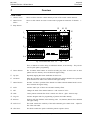
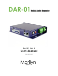
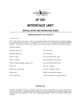
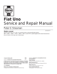
MC 1616
MEMORY LIGHTING CONTROLLER
Software Revision 1.08 and above
OPERATION MANUAL
MC 1616
MEMORY LIGHTING CONTROLLER
OPERATION MANUAL
Software Revision 1.08 and above
Document Revised: 8/31/985
Copyright 1998
NSI CORPORATION
Tualatin, OR
MC 1616
Software Revision 1.08 and above
Table of Contents
Introduction
Welcome . . . . . . . . . . . . . . . . . . . . . . . . . . . . . . . . . . . . . . . . . . . . . . . . . . . . . . . . . . . . . . . . . . . . . . . . . . . . . . 1
Installation\Setup
Power Supply Requirements. . . . . . . . . . . . . . . . . . . . . . . . . . . . . . . . . . . . . . . . . . . . . . . . . . . . . . . . . . . . . . . 2
Dimmer Equipment Connection . . . . . . . . . . . . . . . . . . . . . . . . . . . . . . . . . . . . . . . . . . . . . . . . . . . . . . . . . . . . 2
Overview
Front Panel. . . . . . . . . . . . . . . . . . . . . . . . . . . . . . . . . . . . . . . . . . . . . . . . . . . . . . . . . . . . . . . . . . . . . . . . . . . . . 3
Rear Panel . . . . . . . . . . . . . . . . . . . . . . . . . . . . . . . . . . . . . . . . . . . . . . . . . . . . . . . . . . . . . . . . . . . . . . . . . . . . . 4
Operation Guide
General . . . . . . . . . . . . . . . . . . . . . . . . . . . . . . . . . . . . . . . . . . . . . . . . . . . . . . . . . . . . . . . . . . . . . . . . . . . . . . . . 5
Configuration . . . . . . . . . . . . . . . . . . . . . . . . . . . . . . . . . . . . . . . . . . . . . . . . . . . . . . . . . . . . . . . . . . . . . . . . . . . 5
Bump Buttons . . . . . . . . . . . . . . . . . . . . . . . . . . . . . . . . . . . . . . . . . . . . . . . . . . . . . . . . . . . . . . . . . . . . . . . . . . 5
Pattern Select Buttons . . . . . . . . . . . . . . . . . . . . . . . . . . . . . . . . . . . . . . . . . . . . . . . . . . . . . . . . . . . . . . . . . . . . 5
Tap Sync Button . . . . . . . . . . . . . . . . . . . . . . . . . . . . . . . . . . . . . . . . . . . . . . . . . . . . . . . . . . . . . . . . . . . . . . . . 5
Chase Rate Slider . . . . . . . . . . . . . . . . . . . . . . . . . . . . . . . . . . . . . . . . . . . . . . . . . . . . . . . . . . . . . . . . . . . . . . . 5
Fade Rate Slider . . . . . . . . . . . . . . . . . . . . . . . . . . . . . . . . . . . . . . . . . . . . . . . . . . . . . . . . . . . . . . . . . . . . . . . . 6
Glide Button . . . . . . . . . . . . . . . . . . . . . . . . . . . . . . . . . . . . . . . . . . . . . . . . . . . . . . . . . . . . . . . . . . . . . . . . . . . 6
Audio Button and Slider. . . . . . . . . . . . . . . . . . . . . . . . . . . . . . . . . . . . . . . . . . . . . . . . . . . . . . . . . . . . . . . . . . 6
Manual Button . . . . . . . . . . . . . . . . . . . . . . . . . . . . . . . . . . . . . . . . . . . . . . . . . . . . . . . . . . . . . . . . . . . . . . . . . . 6
Channel Level Sliders . . . . . . . . . . . . . . . . . . . . . . . . . . . . . . . . . . . . . . . . . . . . . . . . . . . . . . . . . . . . . . . . . . . . 6
Go Button . . . . . . . . . . . . . . . . . . . . . . . . . . . . . . . . . . . . . . . . . . . . . . . . . . . . . . . . . . . . . . . . . . . . . . . . . . . . . 7
Add button . . . . . . . . . . . . . . . . . . . . . . . . . . . . . . . . . . . . . . . . . . . . . . . . . . . . . . . . . . . . . . . . . . . . . . . . . . . . . 7
Blackout Button. . . . . . . . . . . . . . . . . . . . . . . . . . . . . . . . . . . . . . . . . . . . . . . . . . . . . . . . . . . . . . . . . . . . . . . . . 7
Master Slider . . . . . . . . . . . . . . . . . . . . . . . . . . . . . . . . . . . . . . . . . . . . . . . . . . . . . . . . . . . . . . . . . . . . . . . . . . . 7
Program Button . . . . . . . . . . . . . . . . . . . . . . . . . . . . . . . . . . . . . . . . . . . . . . . . . . . . . . . . . . . . . . . . . . . . . . . . . 7
Programming Control Functions
Patterns . . . . . . . . . . . . . . . . . . . . . . . . . . . . . . . . . . . . . . . . . . . . . . . . . . . . . . . . . . . . . . . . . . . . . . . . . . . . . . . . 8
Quick Programming Chase Patterns . . . . . . . . . . . . . . . . . . . . . . . . . . . . . . . . . . . . . . . . . . . . . . . . . . . . . 8
Programming Chase Using Sliders. . . . . . . . . . . . . . . . . . . . . . . . . . . . . . . . . . . . . . . . . . . . . . . . . . . . . . 8
Audio Sync . . . . . . . . . . . . . . . . . . . . . . . . . . . . . . . . . . . . . . . . . . . . . . . . . . . . . . . . . . . . . . . . . . . . . . . . . . . . 8
Synchronizing Chase Patterns . . . . . . . . . . . . . . . . . . . . . . . . . . . . . . . . . . . . . . . . . . . . . . . . . . . . . . . . . . 9
Programming Audio Intensity Effects . . . . . . . . . . . . . . . . . . . . . . . . . . . . . . . . . . . . . . . . . . . . . . . . . . . 9
MC 1616
Software Revision 1.08 and above
Console Configuration
Rear Panel Dipswitch . . . . . . . . . . . . . . . . . . . . . . . . . . . . . . . . . . . . . . . . . . . . . . . . . . . . . . . . . . . . . . . . . . 10
MIDI Settings. . . . . . . . . . . . . . . . . . . . . . . . . . . . . . . . . . . . . . . . . . . . . . . . . . . . . . . . . . . . . . . . . . . . . . . . . 11
MIDI Implementation . . . . . . . . . . . . . . . . . . . . . . . . . . . . . . . . . . . . . . . . . . . . . . . . . . . . . . . . . . . . . . . . . . 11
Note On / Note Off . . . . . . . . . . . . . . . . . . . . . . . . . . . . . . . . . . . . . . . . . . . . . . . . . . . . . . . . . . . . . . . . 11
Control Changes . . . . . . . . . . . . . . . . . . . . . . . . . . . . . . . . . . . . . . . . . . . . . . . . . . . . . . . . . . . . . . . . . . . 11
System Exclusive . . . . . . . . . . . . . . . . . . . . . . . . . . . . . . . . . . . . . . . . . . . . . . . . . . . . . . . . . . . . . . . . . . 11
Specifications
Console Specifications . . . . . . . . . . . . . . . . . . . . . . . . . . . . . . . . . . . . . . . . . . . . . . . . . . . . . . . . . . . . . . . . . . 12
Trouble Shooting
Checklist . . . . . . . . . . . . . . . . . . . . . . . . . . . . . . . . . . . . . . . . . . . . . . . . . . . . . . . . . . . . . . . . . . . . . . . . . . . . . 13
Warranty
NSI Corporation Limited Warranty . . . . . . . . . . . . . . . . . . . . . . . . . . . . . . . . . . . . . . . . . . . . . . . . . . . . . . . 14
MC 1616
Software Revision 1.08 and above
1
Introduction
Welcome
Introduction
Welcome
You are entering a new era of microprocessor controlled stage lighting technology. The
powerful NSI Micro-Plex designs involve the electrical marriage of microprocessor technology
and digitally controlled multiplexing. The result is a control package with the flexibility for
a variety of innovative applications.
The NSI MC 1616 Lighting Console features an advanced microprocessor based design
containing many benefits found in today’s personal computers. This technology provides for
the option of adding programmable Memory Scene Masters and Chase effects to the simplicity
of a familiar two scene console.
The NSI Micro-Plex technology found in all NSI products allows components of your lighting
system to be interconnected by way of standard 3-conductor microphone cables or audio
snakes. Up to 128 individual control signals may be transmitted to dimmer packs through
a single microphone cable and the returned phantom power eliminates the need for AC power
cords on NSI controllers. This makes the remote placement of the MC 1616 Lighting Console
easy and convenient.
The NSI MC 1616 Lighting Console represents our continuing commitment of leading the
industry in defining technological advances for stage lighting.
Welcome to the era of microprocessor controlled stage lighting!
NSI CORPORATION
Features and Specifications may change without notice
1
Installation\Setup
Power Supply Requirements
2
Power Supply
Requirements
MC 1616
Software Revision 1.08 and above
Installation\Setup
The MC 1616 Lighting Console requires a source of 15 volts DC (at least 250 MA) to operate
satisfactorily. When used with NSI dimming equipment, power is provided through the
Micro-Plex microphone cord connection system when connected to the dimmers.
If the console is equipped with the optional DMX-512 output and used with DMX-512
controlled dimmers or if the microphone cable length exceeds 100 feet, the external power
supply jack can be used to apply power to the console. Use the power supply provided with
the DMX-512 option or call your dealer for assistance in obtaining a proper supply. Make
sure that the plug on any power supply not supplied through NSI is configured so that the
center connector is positive.
Dimmer
Equipment
Connection
Connecting the MC 1616 Lighting Console to NSI dimming equipment is very simple. You
need only connect a single 3 conductor audio cable (standard microphone cable equipped
with a 3-pin XLR type connector) to either of the jacks marked MICRO-PLEX on the rear
apron of the console. It doesn’t matter which jack is used, two jacks are provided for
convenience. Connect the other end of the cable to the NSI dimming equipment.
Fig. 1 Dimmer Output Connectors
If the console is equipped with the DMX-512 option, connection to the dimming equipment
is provided through the 5 pin XLR type connector located on the rear apron of the console.
This connector adheres to the USITT standard on DMX-512 and will support up to 16 dimmer
channels with one 3 wire cable. Since remote power is not provided on this connector, the
power supply included with the DMX-512 option must be used.
2
Features and Specifications may change without notice
NSI CORPORATION
MC 1616
Software Revision 1.08 and above
3
Overview
Front Panel
Overview
Front Panel
1. Channel Levels
These 16 LED’s show the current intensity of each of the console control channels.
2. Manual Scene
Sliders
These 16 slide controls are used to control and/or program the intensities of channels
16.
1-
3. Bump Buttons
14 15
13
16
1
2
5
6
7
3
8
4
12
Fig. 2 Front Panel MC 1616
9
10
11
These 16 buttons are used to bring an individual channel, to full intensity. They also are
used for quick pattern programming.
4. Pattern Buttons
The 16 Pattern Select buttons are used for activating any of the 16 static scenes or chase
patterns stored in memory. Press and hold will bypass fading.
5. Tap Sync
Repeatedly tapping this button establishes the chase rate.
6. Go Button
When the Go button is pressed, all lights will fade to the current channel levels represented
by the channel level sliders. Press and hold will bypass fading.
7. Manual Button
Provides ‘‘real time’’operation of the channel level sliders when the Manual mode is active.
Press and hold will bypass fading.
8. Audio
Activates audio sync of chase rate and audio intensity effects.
9. Add
Changes the mode of the Pattern buttons to ‘‘add’’ instead of ‘‘kill’’.
10. Glide
Causes patterns activated after Glide is turned on to fade or ‘‘glide’’ between steps.
11. Program
Activates Program mode for programming of patterns and audio intensity.
12. Blackout
Each tap will clear functions in the following order: GO, Patterns, Manual. Press and hold
will bypass fading.
13. Audio Level
This slider controls the sensitivity of the audio automatic gain control circuit. Adjust for
best effect with audio.
14. Chase Rate
This Slider controls the speed at which the patterns sequence (chase).
NSI CORPORATION
Features and Specifications may change without notice
3
Overview
Rear Panel
MC 1616
Software Revision 1.08 and above
15. Fade Rate
This slider sets the initial fade in and out of patterns and other functions.
16. Master Level
This control sets the maximum level to stage. It does not affect the Channel level Leds.
Rear Panel
1. Micro-Plex Outputs
These 2 outputs provide NSI’s microphone dimmer connection via a 3 pin XLR type connector.
Either connector may be used (1-Male, 1-Female).
2. DMX-512
This optional output is used to provide dimmer control information to dimmers using this
protocol. Its 5 pin Female XLR connector conforms to the USITT standard.
3
4
5
2
6
1
Fig. 3 Rear Panel MC 1616
3. AUX DC Power
This input jack allows a standard wall transformer rated at 15v DC (at least 200 MA) to
provide power to the MC 1616 console.
4. Audio Input
This jack accepts a line level audio input signal to synchronize chase and provide audio
intensity effects.
5. Configuration Dip
Switch
These switches allow customization of some console functions.
6. MIDI In/Out/Thru
Midi ports for connection to a sequencer or MIDI storage device.
4
Features and Specifications may change without notice
NSI CORPORATION
MC 1616
Software Revision 1.08 and above
4
General
Operation Guide
General
Operation Guide
The MC 1616 Lighting Console consists of a manual 16 channel scene, a set of bump buttons,
and 16 programmable memories that can be static scenes or chases. The console is designed
to allow tailoring to your needs.
To give the user channel intensity feedback, channel intensity LED’s are provided above
each of the slide controls. These LED’s show relative intensities from all console functions
and are not affected by the Master control.
Configuration
The MC 1616 has several features that can be customized to your applications. If changes
are desired, please see the section on Console Configuration.
IMPORTANT: If this is the first time you will be using the console or if you experience
any problems such as dimmers not responding or other unusual operation, the configuration may have been accidently changed. See section on Console Configuration.
Bump Buttons
Underneath the channel level slide controls are 16 momentary push buttons. These buttons
are used to bump each individual channel to full intensity regardless of the Blackout button
or the setting of the Master control.
Note: In Programming mode, the bump buttons serve a special function and will not
affect stage lighting.
Pattern Select
Buttons
The 16 Pattern Select buttons are used for activating any of the 16 static scenes or chase
patterns stored in memory. A tap of any of the Pattern Select buttons will light the LED
above the button and cause the pattern or scene stored in memory to fade in at the set fade
rate. A second tap of the button will cause the LED to go off and the pattern or scene will
fade out at the set fade rate.
Pressing and holding down any of the Pattern Select buttons will bypass the set fade rate
and cause all patterns or scenes to fade in or out instantly (after a short delay).
Pattern Select buttons operate normally in the ‘‘kill’’mode, whereas pressing one button will
‘‘kill’’ other patterns that are active and cause them to fade out while the selected pattern
fades in. If the button is held down then the fades are instant.
Pressing the Add button will put the patterns in the ‘‘add’’mode and all patterns will operate
independently of each other.
The console may be configured such that the top row of patterns (1-8) may be locked into
the ‘‘add’’ mode. See section on Configuration.
Tap Sync
Button
The Tap Sync button is used to set and synchronize the chase rate (the rate at which all
patterns will sequence) by tapping the button several times. The chase rate will synchronize
to the time of the last two taps. The LED above the Tap Sync button will flash at the new
chase rate. The chase rate may be set anytime whether or not a pattern is running.
Tap Sync will override any previous setting of the chase rate control slider until the slider
is moved again.
Chase Rate
Slider
The Chase Rate slider adjusts the chase rate (the rate at which all patterns will sequence).
The rate is indicated by the red led located directly above the Tap Sync button.
To disable chasing, move the Chase Rate slider up and then all the way down. Moving this
slider will always override Tap Sync.
NSI CORPORATION
Features and Specifications may change without notice
5
Operation Guide
Fade Rate Slider
MC 1616
Software Revision 1.08 and above
Fade Rate
Slider
The MC 1616 has an autofader to provide automatic crossfades from one pattern or scene
to another. The Fade Rate slider determines the speed at which the fade will occur. The
fade will happen instantly when this control is in the fully down position and causes increasingly
slower fades as the control is raised. Fade rate is overridden by pressing and holding most
functions.
Glide Button
The Glide button is used to turn on and off the Glide mode. Any pattern selected after the
Glide mode is turned on will fade or ‘‘glide’’between chase steps instead of instantly changing.
The rate of the change is determined by the time between steps (chase rate).
The Glide mode is activated by tapping the Glide button until the Glide led lights. The
Glide mode is turned off by again tapping the button. Turning on or off the Glide mode
will not affect patterns that are already running.
Audio Button
and Slider
Audio chase sync may be activated by tapping the Audio button until the led above it lights
and then by adjusting the sensitivity control for desired effectiveness. The patterns will
sequence on the audio beat (if discernable) in conjunction with the Tap Sync or Chase Rate
slider. If a chase rate is set, then the chase will resynchronize at each audio beat. If audio
alone is desired, move the Chase Rate slider up and then all the way down to disable.
Pressing the Audio button a second time will disable the Audio mode.
Audio intensity effects may be programmed into any channel by using the Program button.
This will cause desired channels to flash to audio whenever the Audio mode is on. See the
section on PROGRAMMING.
Manual
Button
The Manual button allows manual intensity control of the 16 lighting channels. The first
tap of the manual button will light the led above it and cause the channels to fade up to the
intensity set by the channel level sliders. After the fade up is complete, changes to the
lighting levels can be made by simply moving the channel level slide controls.
A second tap of the Manual button will cause the led above it to go out and the lighting
levels set by the slide controls will fade out at the set fade rate. Pressing and holding the
Manual button will bypass the set fade rate and cause the manual scene to fade in or out
instantly.
All channel levels set by the Manual scene will be added to levels produced by other console
functions with the greatest level having precedence.
The Manual scene may be reset by a second tap of the blackout button if the console is so
configured. The Manual scene may also be configured to be locked on, disabling the Manual
button. See section on configuration.
Channel
Level Sliders
The Channel Level Sliders are used to vary the output levels of the 16 individual control
channels. These levels can be used in programming patterns or scenes. They can also be
used to directly control the channel levels on stage through the use of the Manual button. If
the Manual scene is locked on, then these sliders will always control stage levels. See section
on Console Configuration.
All channel levels set by the Manual scene will be added to levels produced by other console
functions with the greatest level having precedence.
6
Features and Specifications may change without notice
NSI CORPORATION
MC 1616
Software Revision 1.08 and above
Go Button
Operation Guide
Go Button
The Go button causes all lights to fade to the current levels represented by the settings of
the Channel Level sliders. The lighting levels will be added to the Pattern scenes and any
other active scenes or functions with the greatest level having precedence.
Changing the channel level sliders and pressing the Go button additional times, will cause
the old scenes to fade out and new scenes to fade in.
Pressing and holding the Go button will bypass Fade rate and cause the scene to change
instantly.
You may clear the Go scene by tapping the Blackout button once.
Add button
The Add button changes the mode of the Pattern buttons. Normally the Pattern buttons are
in a ‘‘kill’’mode, whereas pressing any Pattern button will ‘‘kill’’other active Pattern buttons.
This way only one pattern is on at a time.
The Add mode is activated by pressing the Add button and illuminating the LED above it.
When active, Pattern buttons will not ‘‘kill’’ other patterns allowing multiple patterns to be
on at a time. Pressing the Pattern buttons a second time will deactivate them.
Note: The Add mode may be configured to affect only the bottom row of pattern buttons,
leaving the top row independently in the ‘‘kill’’ mode.
Blackout
Button
Each tap of the Blackout button will cause functions to deactivate or ‘‘clear’’ in the following
order.
1. Go function.
2. Patterns.
3. Manual Mode.
It may require up to three taps of the Blackout button to entirely clear all functions.
The Blackout Led will light when the Go function, all patterns, and the Manual scene button
have been deactivated.
Lights affected by each function will fade out at the set fade rate.
Pressing and holding down the Blackout button will bypass the set fade rate and cause the
selected functions to fade out instantly.
Master Slider
The Master slide control provides proportional level control over all console functions to
stage with the exception of the Bump buttons. For example:
Whenever the Master slide control is at minimum all stage outputs will be at zero except for
any resulting from a Bump button.
If the Master is at 50% all stage outputs will be at only 50% of their current console settings
except for any resulting from a Bump button.
If the Master is at full all stage outputs will follow the console settings.
Program
Button
NSI CORPORATION
The Program button is used to program chase patterns or static scenes into the pattern memory
or to program audio intensity effects. For programming details see the next section on
PROGRAMMING.
Features and Specifications may change without notice
7
Programming Control Functions
Patterns
5
MC 1616
Software Revision 1.08 and above
Programming Control Functions
Patterns
Up to 16 Patterns may be stored in the memory of the MC 1616 and may be recalled at the
touch of a button. A Pattern may be either a single scene (static scene) or a sequence of
scenes (chase). All programming is stored in non-volatile memory which retains information
for at least 10 years, even when power is removed.
Quick
Programming
Chase Patterns
A chase pattern consisting of steps in which the lights on either fully on or fully off may
be programmed very quickly for any of the Pattern buttons. The Bump buttons are used to
create the chase steps. Follow these steps to quick program a chase:
1.
Tap the Program button until the LED above it lights. If the LED does not light, the memory
lock is on.
2.
Select the pattern to program by tapping one of the 16 Pattern Select buttons causing the
LED above the button to flash. This will erase the current memory programming for this
button.
3.
Press and hold the desired Bump buttons(s) for this step of the chase. The levels will not
appear on the stage but will be displayed on the channel level LEDs.
4.
Releasing all the bump buttons will automatically program this step into memory. Repeat
step 3 until the desired number of steps is programmed.
5.
Tap the Blackout button to exit from the programming mode.
Programming
Chase Using
Sliders.
Static scenes or Chase sequences with varying levels may be programmed into any of the
Pattern Select buttons using the Slide controls.
Programming in this manner will provide control over channel intensity for each step,
but pattern memory will be used up eight times as fast as when using the bump buttons.
Follow these steps to program patterns using the slide controls:
1.
Tap the Program button until the LED above it lights. If the LED does not light, the memory
lock is on.
2.
Select the pattern to program by tapping one of the 16 Pattern Select buttons causing the
LED above the button to flash. This will erase the current memory programming for this
button.
3.
Move the channel level slide controls to the levels desired for this step of the chase. The
levels being programmed will not appear on stage unless the Manual scene is selected using
the Manual button.
4.
Tap the Program button to program this step into memory.
5.
If programming a static scene, tap the Blackout button now to exit the programming mode.
If programming a chase pattern, repeat steps 3 and 4 until the desired number of steps is
programmed. Tap the Blackout button when done to exit the programming mode.
NOTE: If the Program LED extinguishes before the blackout button is tapped, the
memory is full.
8
Features and Specifications may change without notice
NSI CORPORATION
MC 1616
Software Revision 1.08 and above
Audio Sync
Programming Control Functions
Audio Sync
An audio signal may be supplied to the MC 1616 console via the phon0 jack located on the
back of the unit. The audio signal can be used to synchronize the chases to the beat of the
audio and to affect the intensity of predetermined channels.
Synchronizing
Chase Patterns
To synchronize chases; activate the audio mode by tapping the Audio button until the LED
above it lights. Now activate a chase pattern and move the Chase Rate control to the minimum
position. Move the Audio Sensitivity slide control slowly up until the desired effect is
achieved.
Programming
Audio Intensity
Effects
The Audio mode may be programmed to flash desired channels to the intensity of the audio
signal whenever the Audio mode is on by following these steps:
NSI CORPORATION
1.
Tap the Program button until the LED above it lights. If the LED does not light, the memory
lock is on.
2.
Select channels to be affected by audio by moving the corresponding channel level sliders
to maximum, and move the remaining channel level sliders to minimum.
3.
Tap the Audio button to program the audio intensity effects into memory.
Features and Specifications may change without notice
9
Console Configuration
Rear Panel Dipswitch
MC 1616
Software Revision 1.08 and above
6
Console Configuration
Rear Panel
Dipswitch
The 8 Dipswitches on the rear panel serve special functions as follows:
Factory default is all switches off (up):
#1
MEMORY LOCK:
OFF (up) = Unlocked
ON (down) = Locked
#2
MICROPLEX MODE:
OFF (up) = Normal
ON (down) = Special
#3
CONFIGURE TAP BUTTON
OFF (up) = Tap Sync
ON (down) = Manual step chase
#4
CONFIGURE LOCK:
OFF (up) = Unlocked
ON (down) = Locked
#5
PATTERN 1-8 ADD MODE:
OFF (up) = Normal
ON (down) = Always ADD mode
#6
MANUAL SCENE:
OFF (up) = Normal
ON (down) = Not deactivated by Blackout
#7
MANUAL SCENE:
OFF (up) = Normal
ON (down) = Always activated.
#8
RESERVED:
Memory Lock
The entire memory of the MC 1616 can be physically locked to prevent accidental changes
to the programmed patterns or scenes. This is highly recommended whenever the console
is not expected to be reprogrammed for a period of time.
If programming is attempted on a locked console, the Program LED will not light upon
tapping the Program Button.
10
TO LOCK MEMORY:
Place Dipswitch #1 in the ON (down) position.
TO UNLOCK MEMORY:
Place Dipswitch #1 in the OFF (up) position.
Features and Specifications may change without notice
NSI CORPORATION
MC 1616
Software Revision 1.08 and above
MIDI Settings
Console Configuration
MIDI Settings
To change MIDI settings follow these steps:
1.
Place both dipswitch #1 and #4 in the OFF (up) positions.
2.
Hold scene select buttons 13-16 down at the same time while applying power to the unit
3.
Select Midi setting desired by pressing the appropriate Pattern Select button as listed below
and follow instructions. The currently defined setting will be indicated on the channel level
LEDs by a flashing LED.
Pattern #1: MIDI SEND CHANNEL Pattern #2: MIDI RCV. CHANNEL
After pattern #1 or #2 is pressed, the current MIDI channel is displayed by lighting the
corresponding channel level LED. To change channel; tap the Bump button of the corresponding
channel. When done, tap the Blackout button followed by another Pattern Select for additional
settings or tap Blackout again to exit MIDI Setting Mode.
Pattern #3: MIDI MEMORY DUMP
Pressing button #3 prepares the console for a Memory Dump to a MIDI disk or any other
MIDI storage unit. The dump is approximately 32K bytes. To initiate, press Pattern #3
button again. When the transfer is complete, the pattern select LED will flash. At this press
the Blackout button to leave the MIDI Setting Mode.
MIDI
Implementation
The MC 1616 will send and receive MIDI program changes according to the following table:
PROG CHNG NUMBER
0 - 15
16 - 31
97
113
114
123
124
125
Note On / Note
Off
FUNCTION
Turn on patterns 1-16
Turn off patterns 1-16
Blackout
Glide off
Glide on
Step Change
Manual On
Manual Off
The MC 1616 will transmit and receive Note On and Note Off data via the bump buttons.
Velocity is transformed into channel intensity and note numbers correspond to the following
lighting channels.
NOTE NUMBER
96 - 111
CHANNEL
1 - 16
Control
Changes
Control change #1 is sent whenever a Pattern, Manual, or Blackout button is pressed. The
current fade rate is sent as a value of the control change. When receiving a control change
#1, the current setting of the fade rate slider is overridden until the slider is moved.
System
Exclusive
A System Exclusive Message is sent as a memory dump. Upon receiving the Sys Ex, the
console will erase and reload memory automatically.
NSI CORPORATION
Features and Specifications may change without notice
11
Specifications
Console Specifications
MC 1616
Software Revision 1.08 and above
7
Specifications
Console
Specifications
Control Channels
16
Dimmers
16
Patterns (memory)
16
Maximum Steps
approx. 400 total
Memory
Non-volatile EEPROM
(approx. 10 year retention)
Dimmer Outputs
NSI Micro-plex
DMX-512 (optional)
12
Input Power
15 volts DC, minimum 250ma.
Dimensions (HxWxD)
(2 3/4" x 16 5/8" x 9")
Weight (approx.)
5.0 lbs
Features and Specifications may change without notice
NSI CORPORATION
MC 1616
Software Revision 1.08 and above
8
Trouble Shooting
Checklist
Trouble Shooting
Checklist
Manual mode will not turn off.
• Configuration set wrong, see section on Console Configuration.
Tap Sync does not sychronize
chase
• Configuration set wrong, see section on Console Configuration.
Fade rate intermittent.
• Holding down some buttons will override faderate and cause an instant
fade.
NSI Technical Services (503) 682-6228
NSI CORPORATION
Features and Specifications may change without notice
13
Warranty
NSI Corporation Limited Warranty
9
MC 1616
Software Revision 1.08 and above
Warranty
NSI
Corporation
Limited
Warranty
NSI Corporation warrants new electronics products to be free from defective materials and
workmanship for a period of one (1) year from the date of purchase to the original owner
when purchased from an authorized NSI dealer.
The purchaser is responsible for completing and mailing to NSI, within 15 days of purchase,
the warranty registration card enclosed with each product. NSI products that have been
subject to accident, alteration, abuse, or defacing of the serial number are not covered by
this warranty. The normal wear and tear of items such as knobs, jacks, and switches are not
covered under this warranty.
If your NSI product requires service during the warranty period, NSI will repair or replace,
at its option, defective materials provided you have identified yourself as the original owner
of the product to NSI or any authorized NSI dealer. Transportation charges to and from an
authorized dealer or the NSI factory for repair shall be the responsibility of the owner. All
products returned to NSI must have factory authorization for return prior to shipping.
NSI Corporation is not liable for any incidental or consequential damages resulting from
defect or failure other than repairs of the NSI product subject to the terms of this warranty.
This warranty gives you specific legal rights, and you may have other rights which vary from
state to state. This warranty is expressly in lieu of all other agreements and warranties
expressed or implied except as may be otherwise required by law.
14
Features and Specifications may change without notice
NSI CORPORATION