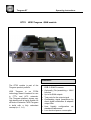
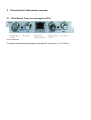
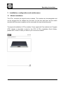
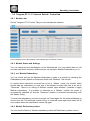
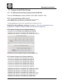
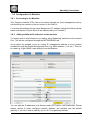
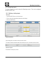
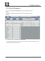
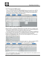
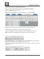
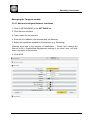
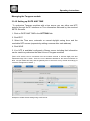
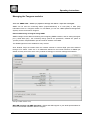
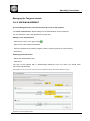
1
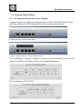
GT 01W Tangram with GT23 EdgeQAM ( IP to QAM ) GT 01 WISI Tangram chassis Tangram GT GT23 Operating instructions WISI Tangram QAM module Features: The GT23 module is part of the Tangram product portfolio. WISI Tangram is an FPGA technology based Headend for use in FTTx and HFC networks. The Tangram platform shows very high density and is highly flexible for all kinds of networks. WISI Tangram is build with a fully redundant concept (n+1, 1+1). Gigabit Ethernet MPEG-TS to DVB-C QAM Processor Optionally (De-)scrambling + MUX function Up to 8x QAM outputs Test ports for the output signal Outstanding signal parameters by direct digital modulation & adapted output filter User friendly configuration via standard Webbrowser Low electrical power consumption This page is intended to be empty Tangram GT Operating instructions Table of contents 1 Safety instructions ............................................................................................................... 6 1.1 2 Technical data / Mechanical overview................................................................................. 7 2.1 3 ESD protection ............................................................................................................. 6 GT2x Module Front view ............................................................................................. 7 Installation, configuration and maintenance ........................................................................ 8 3.1 Module installation ....................................................................................................... 8 3.2 Tangram Front IP Ports.............................................................................................. 10 3.2.1 3.3 IP / Ethernet Ports at the Front of Tangram ........................................................ 10 Tangram RF / Video Modules Slots ........................................................................... 11 3.3.1 Chassis slots GT01 ............................................................................................. 11 3.3.2 GT2x Modules ports (example is GT21) ............................................................. 11 3.4 Configuration of Tangram .......................................................................................... 12 3.4.2 Connecting to the default Management IP address: ........................................... 13 3.4.3 SETTINGS Tab: Changing the IP address to your own Network ........................ 13 3.5 Tangram GT11 / 12 Switch modules / Main Control Page ......................................... 14 3.5.1 Main Status GT11- Control ................................................................................. 14 3.5.2 Future GT11 main updates / upgrades ............................................................... 14 3.6 Tangram GT11 / 12 internal Switch / Control tab ....................................................... 15 3.6.1 Modules tab ........................................................................................................ 15 3.6.2 Module Status and Settings ................................................................................ 15 3.6.3 n+1 Module Redundancy .................................................................................... 15 3.6.4 Module Redundancy status ................................................................................ 15 3.7 Tangram Front IP Port Groups................................................................................... 16 3.7.1 3.8 IP / Ethernet Ports Groups ................................................................................. 16 Configuration of Modules ........................................................................................... 17 3.8.1 Connecting to the Modules: ................................................................................ 17 3.8.2 Adding additional IP addresses to the modules .................................................. 17 3.9 Tangram & SW options .............................................................................................. 19 3.9.1 Connect to WISI portal & activating the output Modules: .................................... 19 3.11 Configuring Inputs ....................................................................................................... 20 3.11.3 Redundant Input Sources .......................................................................................... 23 3.13.5 Service selection and remultiplexing .......................................................................... 31 Service selection and remultiplexing (cont.) ......................................................................... 32 4. GT23 Module Status Information ...................................................................................... 44 5. GT23 Module LEDs & Alarms ........................................................................................... 45 5.1 GT23 board..................................................................................................................... 45 5.5.1 Status LED states ............................................................................................... 45 5.5.2 Status LED indication.......................................................................................... 46 Document Revision Information Date finished 22.12.2011 22.08.2012 04.09.2012 11.09.2012 05.11.2012 06.12.2012 Document Rev. 0.1- 0.9 1.0 1.1-1.3 1.4-1.47 1.48-1.49 1.50-1.51 GT23 SW Version 0.9 1.0 1.0 1.1 1.2 1.3 Description Name Versions for Pre-GT Adapted for GT in PP WISI doc. design, Updates GT11 TDG Updates Module Updates, System config TDG Inputs, Updates PK , a2b HP,KD KD KD KD KD Tangram GT Operating instructions 1 Safety instructions 1.1 ESD protection This product contains electrostatic sensitive devices. These devices can be damaged or effectively destroyed by electrostatic discharge (ESD) during unpacking, installation, removal, storage, or shipment if incorrectly handled. Please note that discharge might go unnoticed by a user. Always take normal static precautions when handling the equipment! 2 Technical data / Mechanical overview 2.1 GT2x Module Front view (example is GT21) GT2x module view For best performance please always terminate the Test-points (z = 75 Ohms). Operating instructions 3 Installation, configuration and maintenance 3.1 Module installation The GTxx modules are single function modules. The modules are hot-swappable and can be plugged into the chassis from the back. On the front side there are the switch modules plus the power supplies and the removable fan tray behind the panel. The physical Installation of GTxx modules, Power supplies & Fan modules into Tangram GT01 chassis is described in detail in the GT01 & GTxx Installation Quick Guides, please refer to them in case you have to put or remove a module. 412 xxx Operating instructions This page is intended to be empty -9- Operating instructions 3.2 Tangram Front IP Ports 3.2.1 IP / Ethernet Ports at the Front of Tangram Tangram has up to 9x GigE ports at the front side, 5x RJ-45 100/1000T with GT11 and optionally additional 4x SFP ports with GT12 at the upside position (Slot 8). Tangram with GT11 Switch module (Slot 7) Tangram equipped with GT11 & GT12 Switch modules The numbering on Tangram is always from down to up and from left to right, the first lower Port on GT11 left is determined for out-of-band Management. Port numbering on GT11 & GT12 - 10 - Operating instructions 3.3 Tangram RF / Video Modules Slots RF Modules and Ports at the Rear of Tangram 3.3.1 Chassis slots GT01 Tangram has up to 6 module slots on the rear side. Tangram rear view (Example) The numbering on Tangram modules is always from down to up and from left to right, the first lower Module on the left (seen from the back) is the first, second is above. 3.3.2 GT2x Modules ports GT2x module view (example is GT21) The numbering of Ports on the RF modules is again from left to right, starting with the Test-point of the first RF output. To get best level detection accuracy please always terminate the Testpoints with the 75 Ohms terminator delivered or comparable. - 11 - Operating instructions 3.4 Configuration of Tangram 3.4.1 Connecting to the Tangram Web UI (GUI) Connecting with web browser Use a standard web browser on your computer to connect by typing the IP address of the Tangram in the address field. Supported web browsers The Tangram web interface is verified for Firefox version 9 and higher. Other web browsers might work, too - but the functionality cannot be guaranteed. General information about the web interface structure The web UI is designed to get a logical structure for the user/ installer, and an overview of the device via the side tabs and module details via the top tabs. The main SETTINGS tab contains setting about the switch such as Networking, Headend System Management, Operation Mode, Common Interface, SW and Entitlement Upgrade, Maintenance, and Log. The CAM menu, if available, is also displayed in the Common Interface menu under the SETTINGS tab. The main interface while managing services within the modules is the SERVICE MANAGEMENT tab. Here, you will have an overview of the configured inputs and outputs, and you will also manage the service selection and decryption. Before you start managing the services on the modules, you should add and configure the inputs and configure the outputs in their respective tabs. - 12 - Operating instructions 3.4.2 Connecting to the default Management IP address: The Tangram default IP address on the left front management port is 192.168.1.20 (GT11 SW rel. <0.8.1.5 : 192.168.0.11) To access the Tangram Web- Interface please set the IP address on your PC or Network adaptor to an address in the same address subnet & use same network mask. 3.4.3 SETTINGS Tab: Changing the IP address to your own Network It is recommended to change the IP to an unique IP address in your network. Please change the IP address under SETTINGS / NETWORKING. Please always remove completely & newly configure Network- Addresses, the Netmask plus the default gateway. A known NTP Server source can be used for the time of day sync. When finished with the changes press the “Save” button. - 13 - Operating instructions 3.5 Tangram GT11 / 12 Switch modules / Main Control Page 3.5.1 Main Status GT11- Control On the Tangram GT11-Control Status Tab you can monitor overall stats like Alarms, Fans, Power, Temperature, Serial Number and main SW- Version of Tangram . In the left field you can see the GT Modules / Slots identified by the Chassis. 3.5.2 Future GT11 main updates / upgrades In future there will be additional functionality added to Tangram. Firmware- Update or Upgrade for the main switch are applied via the Maintenance Tab. IP- Adresses set & Group membership survive a Main Firmware Update as long not stated differently in the release notes. - 14 - Operating instructions 3.6 Tangram GT11 / 12 internal Switch / Control tab 3.6.1 Modules tab On the Tangram GT11 Control Tab you can maintain the modules: In the left field there are the Modules / Slots identified by the Chassis / Switch. 3.6.2 Module Status and Settings You can check and set the Modules on the Modules tab. You can switch them on /off and can reset them remotely. Additional you can configure Module Redundancy (n+1): 3.6.3 n+1 Module Redundancy You can check and set the Modules Redundancy mode of a module by choosing the Redundancy mode (Master or Reserved) within that `Modules´ Tab column. A module which should be secured has to be in `Master´ mode, the module which should take the redundancy in case one of the Master modules fails has to be set to ´Reserved`. There is no mixing of different module types allowed / possible to apply Module redundancy. If a problem is detected on a “Master” module the power is automatically switched off and the `Reserved´ module is activated simultanously with the Master config. To revert the redundancy you have to switch on Power again for the replaced Module by hand in this tab. The reserved module will go to reserved mode again and switch off its own outputs when the new Module comes up again. 3.6.4 Module Redundancy status You can see the Status of Module redundancy within the Redundancy status column. - 15 - Operating instructions 3.7 Tangram Front IP Port Groups 3.7.1 IP / Ethernet Ports Groups (using internal VLAN IDs) There are Port Groups to easily distribute video traffic of above 1 Gbit: GT11/ 12 reserved Groups (VIDs 10 & 16) - GT11 MGMT Port 0: Connection to GT switch and module web UI. Internal Management net uses VID=16: internal use reserved. - Internal Streaming net I (VID=10) is connected to GT modules slot 1 to 6 Default Port Group Member settings from factory (This are only defaults and not applicable for Tangram Chassis already customized and configured): GT11 internal Jumper J2 not set (factory default 1): - GT11 Port 1 to 4: Connection to GT streaming net A (VID=2) - GT12 Port 1 to 4: Connection to GT streaming net E (VID=6) - Streaming net A (VID=2) is connected to GT modules slot 1 to 6. - Streaming net E (VID=6) is connected to GT modules slot 1 to 6, too GT11 & 12 Port Group- Member settings in the Main Setting Tabs GT11 internal Jumper J2 set (factory default 2): - GT11 Port 1: Connection to GT streaming net A (VID=2) - GT11 Port 2: Connection to GT streaming net B (VID=3) - GT11 Port 3: Connection to GT streaming net C (VID=4) - GT11 Port 4: Connection to GT streaming net D (VID=5) - GT12 Port 1: Connection to GT streaming net E (VID=6) - GT12 Port 2: Connection to GT streaming net F (VID=7) - GT12 Port 3: Connection to GT streaming net G (VID=8) - GT12 Port 4: Connection to GT streaming net H (VID=9) - Streaming net A (VID=2) is connected to GT modules slot 1 and 2. - Streaming net B (VID=3) is connected to GT modules slot 3 and 4. - Streaming net C (VID=4) is connected to GT modules slot 5. - Streaming net D (VID=5) is connected to GT modules slot 6. - Streaming net E (VID=6) is connected to GT modules slot 1 and 2. - Streaming net F (VID=7) is connected to GT modules slot 3 and 4. - Streaming net G (VID=8) is connected to GT modules slot 5. - Streaming net H (VID=9) is connected to GT modules slot 6. - 16 - Operating instructions 3.8 Configuration of Modules 3.8.1 Connecting to the Modules: The Tangram modules GT2x can be accessed through the front management port by just choosing the module on the left column in the Web UI. ( to access all modules wih the same Mangement IP- address through the Switch please make sure that the IP ports 80 to 86 are opened with your Firewalls ) 3.8.2 Adding additional IP addresses to the modules To receive and to send streams you need to setup Streaming interfaces to the Internal Port. This can be configured through the NETWORKING tab. As an option its possible to put an unique IP management address to every module available through the Switch Management Port (e.g. Main address +1,+2, etc.). This can be used e.g. to get SNMP- traps directly from the Modules. You can edit the IP addresses of a Module under SETTINGS / NETWORKING. Please always remove & newly configure network- address, the netmask plus the default gateway. If you don’t want to specifiy put in 0.0.0.0 as gateway address. - 17 - Operating instructions As an further alternative or to recover a problem you may use the backup Control Port on the back of module with default address 192.168.1.20 netmask 255.255.255.0. As with the front port a standard web browser is used to connect by typing the IP address in the address field to get access from the Control Port on the back. If all address settings of Tangram are unknown or lost you can recover on the module control port by using the WISI / a2b IP Supporter tool – it can be downloaded from the WISI portal. - 18 - Operating instructions 3.9 Tangram & SW options 3.9.1 Connect to WISI portal & activating the output Modules: The Tangram modules GT2x (not the chassis itselve and GT11) must be registered at the WISI portal & activated through a entitlement file when they are shipped with the factory default setup. You can get / download that from WISI Web-Portal: The WISI Tangram portal Portal URL: http://www.wisiconnect.tv Connect to the Tangram portal using the URL: http://www.wisiconnect.tv (in case wisiconnect.tv is down / not available temporary you can use http://www.chameleonconnect.tv in the meantime which offers the same functionality and data. 3.9.2 Serial- number / Linking to the Modules: The Tangram module to be activated can be accessed through the main management by just choosing the module on the left column. Please copy / write down the Serial Number out of the Status tab of the module to be activated. 3.9.3 Requesting access to the wisiconnect.tv portal If you do not have yet a password for access to the portal, please click the Request access to Tangram portal link. 3.9.4 Login to the wisiconnect.tv portal Enter your e-mail address and password, and click Login. Only with the first module you have to register once for the Portal. Then after some time to generate your account or if you have forgotten your password & clicked the Reset password link, an e-mail will be sent to the entered e-mail address. The email contains a hyper-link that you should follow to confirm the request for a new password. - 19 - Operating instructions 3.10 Registering Tangram modules to the WISI Tangram portal If you do not have yet a password for access to the portal, please refer to chapter 3.9.3 3.10.1 Registering modules Please copy / write down the Serial Number out of the Status tab of the module to be activated 3.10.2 Downloading SW options (entitlement file) to your PC Go to the tab My Tangrams & enter the serial number of your Tangram module. Click the `Register Tangram` tab to start registering the Tangram GT2x module. Enter the Serial number of your module. Optionally, also enter Module name, Vendor, and Description (these fields are intended for your own use, to be able to track and maintain your installed base). The fields for SLA status and SW options are filled out automatically from the information stored in the WISI Unit Data Base. Click the `Register´ button to register the Tangram. Go to the tab My Tangrams, and click the serial number for the module to download SW options (entitlement file) for. In the Edit Tangram view, click Download file. Save the file to your computer After login & choosing Register Tangram tab number for the module to download SW options (entitlement file). In the Edit Tangram view, click Download file. 3.10.3 Uploading SW options (entitlement file) to your Tangram module GT2x ( via Tangram Web GUI ) Under SETTINGS / SOFTWARE AND ENTITLEMENT UPGRADE, browse for the entitlement file you previously downloaded to your computer. Click Upload, and reboot the module when the upload is ready. 3.10.4 Using the IP Supporter Tool With the Tangram connected to your computer, and your computer connected to Internet, you can upload the entitlement file directly. Select your Tangram GT2x module, and check the Entitlement from WISI / a2b server, and click Upload. - 20 - Operating instructions 3.11 Configuring Inputs To receive streams you need to setup the Streaming sources . This can be configured through the INPUT tab. 3.11.1 Defining / adding inputs Add input 1. Click the INPUTS tab, and Add new input. 2. Type or select the appropriate parameters and settings. 3. Click the SAVE button. Status information After clicking Save, the status of the input will be shown. The status includes information about the interface (tuner etc.), and about services found. Add more inputs Re-iterate the “Add input” process. - 21 - Operating instructions 3.11.2 Configure Input paths & Input redundancy IGMP & Redundant Inputs The Edge modules of Tangram request the IP multicasts over the IGMPv2 or v3 protocol on routers / switches. For each IP multicast address a Primary and Secondary source (IGMPv3 ) or destination address and optionally an A- and B-path path for redundancy can be configured. A and B and even more sources (C,D,E …) can be configured on the WISI Tangram integrated switch and afterwards choosen on the Tangram modules via the internal streaming net ( Net A-> VID2 = VLAN ID 2, see 3.7.1). The Tangram switch has 4 x 1 GbE RJ45 to supply up to 4 Gb / s multicast e.g. over one path distributed to 4 internal VLANs and another 4 x 1 GbE SFPs with optional GT12 for the supply of multicast over secondary and additional paths. Alternative Streaming paths – example Streaming primary path using VID2 - 22 - Operating instructions Alternative Streaming paths – example redundant Streaming path using VID5= E 3.11.3 Redundant Input Sources Alternative Inputs The Tangram modules searchs for a valid input signal always in the following order: Primary -> Alternative 1 -> Alternative 2 -> Alternative 3 - Search for a valid input signal starts always with the logical input position ´Primary` - GTxx module checks during Latency Time (3sec) the input signal. - if a valid signal is detected within Latency Time -> ´operation completed´ and new logical input position is found. - if a valid signal is not detected within Latency Time -> switching to next logical input position. - 23 - Operating instructions This process continues until a valid input signal is detected. The “Linger time” (=waiting period) is the time the Tangram GTxx module waits with a detected signal failure at the current logical input position in order to decide whether action is needed (t >Linger time, then switch to next alternative) or only a brief interruption of signal has appeared at the entrance and no action is needed, to prevent continous input flapping. Alternative Streaming address – example: redundant Input source - 24 - Operating instructions 3.12 Configure QAM outputs 3.12.1 Enable output 1. Click the RF OUTPUTS tab, and choose output #. 2. Select the output by clicking on the + 3. Click on EDIT , then type a Name and select parameters & settings. Enable the Output. 4. Click the SAVE button. 3.12.2 Enable more outputs Re-iterate the “Enable output” process Further configuration of the QAM Outputs can be done firs in the System Management and the Service Management. Note: the modulator will check automatically for a correct setting of RF channels, which have to be inside a 32MHz frequency space. If you setup a new frequency out of this space there will be a conflict message shown and you have to change the complete group of four channels before it gets active. - 25 - Operating instructions 3.12.3 QAM Modulator settings - Select frequency table (CCIR, OIRT) - Enter the output frequency, as a channel number, or manually in MHz - Select the QAM constellation (QAM16, 32, 64, 128 or 256) - Select the QAM spectrum (normal or inverted) - Select the Symbolr ate in kBaud (e.g. 6875 or 6900 kBaud) - Set output carrier level in dBµV (Allowed level range for 4 outputs on the same upconverter is a value between 81dBµV and 111dBµV in 0.5 dBµV steps) Note: Most settings can be left with the default settings for most applications. - 26 - Operating instructions 3.13.1 HEADEND SYSTEM Management HE System Management and DVB Network PSI/SI For creation of a network-wide correct PSI/SI structure in a DVB Network, information about PSI/SI has to be shared between the Tangram modules in the same network. Creating a group of units enables the sharing of PSI/SI information via the selected Multicast/Broadcast address.The basis for such a sharing is that the Tangrams/ Modules are connected via Ethernet, and that a communication is set up between the modules in several Tangram chassis. Headend system management Under SETTINGS, in the HEADEND SYSTEM MANAGEMENT menu, you can select Modules in the same IP network to be members in the same group. When clicking EDIT, all Module in the IP network will be listed by their serial number. You can now add a Module to DVB network out of the list of Selectable units. Click “+” to add a selectable unit to the group. Click “-“ to remove a unit from the group. Please note that the settings done in one Module will automatically update the headend system management settings also for all Modules in the same group. - 27 - Operating instructions HEADEND SYSTEM Management (cont.) Click on the SETTINGS/ HEADEND SYSTEM MANAGEMENT tab to see available units. Detected units are shown and can be checked. - 28 - Operating instructions 3.13.2_Service_Management Click on the SERVICE MANAGEMENT tab to see available inputs and outputs. Service IDs and PIDS of received Input services are shown and can be checked. Service IDs shown in the Tab SERVICE MANAGEMENT The INPUTs and their PIDs are shown starting from INPUT 0 to INPUT n, depending on how many Inputs are configured and received. - 29 - Operating instructions 3.13.3 Transparent QAM outputs Click on the Module SERVICE MANAGEMENT tab and choose the Input MPTS you want to map / connect to the Output QAM. Existing connections are shown and new ones can be added or removed. An input can be sent transparently to an output by selecting “Connect transparently to”: Connect input to output transparently When an input is “connected” transparently to an output, there is no change of the content of the transport stream from input to output, even if it changes dynamically. - All services, with all PIDs are sent from the input to the output - The PSI/SI tables are sent from input to output without any change or modification. In most cases you will share the NIT to include that channel to the Cable-NIT of the network, choose therefore “ON”, same for the Delivery system descriptor. Please fill in the NetworkID “NID” you want the channel appears in the Cable-NIT. The transparent/ transmodulation mode can be used, too - when a complete MPTS for QAM modulation is created for a transport via IP to another Headend. If the overall bandwith does not fit into the output channel the null packets can be removed / “stripped” from the MPTS. - 30 - Operating instructions 3.13.4 Service selection and remultiplexing Service management functionality and pre-requisites The SERVICE MANAGEMENT tab is the main view for handling remultiplexing, service selection, decryption, encryption and PID management. Before starting with the Service management, the inputs and outputs must be defined. Inputs, Outputs, and their available/assigned services The left part of the SERVICE MANAGEMENT view shows the Inputs with their available services. The right part shows Outputs with the names you have typed while configuring the output. By default, Output have no assigned services, no services has been added. To see the services in the inputs or in the outputs, expand the input (or output) by clicking the heading plus sign. The PIDs of each input service can be shown by clicking the + to expand the service. - 31 - Operating instructions Service selection and remultiplexing (cont.) Structure of the available/assigned services under INPUTS and OUTPUTS Input: Each Input/service has 3 columns; Name (service names), SID (service id), and an edit arrow ” >” for adding to output. Assigning services from the inputs to the outputs is done by clicking the arrow > and selecting the output to add the service to in the appearing pop-up boxes. Outputs: Each Output has 6 columns; Name (mux names), TSID (transport stream id), ONID (Original Network id), NID (Network id), LCN (LCN type) and the edit arrow “>” Each Output Service has 5 columns; Name (service name), Provider (service providername), SID (service id), LCN (service LCN number) and the edit arrow ”>” . Every Name & ID can be changed by clicking on the entry in the table or resetted / removed by clicking the arrow “>” - 32 - Operating instructions 3.13.5 Adding and removing services to/from Outputs Adding services to the outputs 1. Click the edit arrow tailing an input service. When you click the arrow, an “Add / Connect” pop-up will appear. 2. Move the mouse pointer to the Add pop-up. 3. Select the Output to add the service. Adding all services to the outputs 1. Click the edit arrow tailing an input. When you click the arrow, an pop-up will appear with “Connect transparently to” and “Add all services to”. 2. Select “Add all services to”, and select the Output to add services to. Removing services from the outputs Removing a single service from an output 1. Click the edit arrow > of an output service. 2. Click “Remove” in the pop-up window. Removing all services from an output 1. Click the edit arrow > of an output. 2. Click “Remove services” in the pop-up window. - 33 - Operating instructions 3.14 Managing the Tangram module Under SETTINGS tab - module specific settings are managed: NETWORKING Networking settings for defining and configuring IP interfaces, and for setting the capabilities for the defined IP interfaces. Note: Every Tangram module has an extra IP port on the Tangram back for separate 10/100 Ethernet management (“Control Port”, default IP 192.168.1.20/24), the module internal GigE port is switched through GT11 switch for streaming & main management. There are no IP addresses defined for the GigE streaming per default and they have to be set accordingly to customer network. Example of Networking setup - 34 - Operating instructions Managing the Tangram module 3.14.1 Add and configure Network interfaces 1. Click on NETWORKING in the SETTINGS tab 2. Click Add new interface 3. Type a name for the interface 4. Enter the IPv4 address, the Netmask and the Gateway 5. Select the capabilities needed for the interface (e.g. Streaming) (Defaults work best in the mayority of installations - Please don’t change the internal VLAN + System/Web Management settings if you aren´t sure, you may loose connection to the module 6. Click SAVE - 35 - Operating instructions Managing the Tangram module 3.14.2 Setting up DATE AND TIME To sychronize Tangram modules with a time source you can either use NTP protocol through the IP interfaces or Time information delivered by the received MPTS- Streams. 1. Click on DATE AND TIME in the SETTINGS tab 2. Click EDIT 3. Select the Time zone, automatic or manual daylight saving timer and the reachable NTP servers (separate by adding a comma after each address) 4. Click SAVE 5. If no NTP is available/ configured a Stream source including that information can be used to synchronize the date & time of Tangram modules (Note: NTP servers can be connected from the modules external or internal GigE ports and switched through GT11 switch. There are no IP addresses defined for the internal Interface for NTP use per default and they and the gateway have to be set for every module accordingly to customer management network. ) Example of a Date & time setting using a NTP server - 36 - Operating instructions Managing the Tangram module 3.14.3 Time scheduling of Output Channels Click on the Module SETTINGS tab and choose the SCHEDULER Existing tasks are shown and new ones can be added: Check first, that the time is set correctly (-> Settings: Date & Time) on the module and choose a Name for the scheduling action to be programmed: - 37 - Operating instructions Managing the Tangram modules With the SNMP tab – SNMP(v2) specific settings like alarm Traps are managed: SNMP can be used for monitoring alarms (traps/notifications) or to read (Get) or write (Set) information from/ to a Tangram module. To use SNMP, you can use a NMS (Network Management System) that is connected to Tangram. External Monitoring of Tangram using SNMP SNMP settings can be edited for defining and configuring SNMP interface, and for setting the Agent port ( =UDP listen port) , the community strings (read & set “passwords”, defaults are “public” & “private”) and the Trap destination port and receiver address of the NMS. The SNMP agent has to be enabled for every module. Note: Module Traps are sended from the modules external or internal GigE ports and switched through GT11 switch. There are no IP addresses defined for the internal Interface for SNMP per default and they have to be set for every module accordingly to customer management network. Example of SNMP Network setup MIB, MIB structure and NMS integration: Please ask WISI support or your WISI representative for the most recent MIB- Definition files for Tangram. - 38 - Operating instructions Managing the Tangram module 3.14.3 Time scheduling (cont.) After choosing the Time of day and the action to be executed click the “SAVE” button to apply: Time schedules are programmed via “Lua” Script commands: The script command consists of: decode.start_service(<decode_instance>,<input_instance>,<service_id>) where the variables stand for: <decode_instance> = Instance of Decoder, starting with 0 (= Instance “One”) <input_instance> = Inputstream no, starting with 0, -> see 3.13.3 <service_id> = Service-ID (SID) of the program The command can be tested & executed with "EXECUTE SCRIPT" button! - 39 - Operating instructions Managing the Tangram module 3.14.5 USER MANAGEMENT Account Management for User authentication & access to the modules The USER MANAGEMENT allows settings of user authentication for the module UI. You can add users, and create passwords for each user: Adding a user and password - Click Add new user, or the green plus - Enter a user name & Enter a password - Confirm the password by entering it again ( There is a warning if they are not the same ) - Click SAVE Enabling password control - Select User authentication ON - Click SAVE The web UI will respond with a “Authentication Required” from now where you should enter user name and password Note: Make sure not to loose your user accounts and passwords! Factory reset will be needed to recover! Example of User management setup - 40 - Operating instructions Managing the Tangram module 3.14.6 Module Software and SW options (Entitlement) If a module is shipped from factory it has no License / Entitlement for operation. Both FW and SW options are uploaded via SOFTWARE AND ENTITLEMENT UPGRADE in the SETTINGS tab. Additionally, there is status information available about the running software version, and if a new software is uploaded, also about the latest uploaded (not yet running) software version. Uploading software options / Entitlement •Click UPLOAD. Click “Browse” in the pop-up to browse for the software options file (*.ent) for this specific Tangram module Note: The SW options file will have the format <serial number>.ent. If you need to, you can download the entitlement file from the wisiconnect.tv portal or please ask your WISI representative •Locate the software options file on your PC, and select it •Click the Upload button Uploading new Firmware •Click UPLOAD. Click “Browse” in the pop-up, and select the software file (*.bin file) to be uploaded from your PC •Click the Upload button •Wait for the upload complete message before rebooting the module •Reboot the module in your maintenance window - 41 - Operating instructions Managing the Tangram module 3.14.7 Module maintenance Module maintenance functions are available within the Maintenance tab: Reboot of the module Some operations, such as upgrading the software, require a reboot to get it active. Click the Reboot button to reboot the unit. During the rebooting process, “Rebooting” will be shown. After rebooting, the web GUI will go automatically to the STATUS tab. Rescue mode In very special circumstances you might need to boot into rescue mode. If you are sure push the Rescue mode button to boot into rescue mode. During the rebooting process, Booting into rescue will be shown. In the rescue mode, you can access basic functionality via web interface, and upload new software and software options. In some cases you may have to connect via the backside control port to get access again. Returning to normal mode Click the Reboot button in the rescue mode to return to normal mode. Note: re-enter the IP address of your Tangram in the address field of you browser to access the normal mode web GUI. - 42 - Operating instructions 3.14.8 Factory reset & Backup / Restore Factory reset The Tangram module can be reset to the same status as when delivered from the factory. Go to the SETTINGS tab, and MAINTENANCE. Before you Click on FACTORY RESET please always do a backup of your last configuration as described below ! It may help you to save time & effort to get back to your original setup. Factory reset from the rescue interface There is a factory reset button in the rescue mode UI. WARNING! Factory reset from the rescue mode will remove all settings, remove the entitlement file enabling the SW options, and will reset the IP address to the default. Backup and restore (saving & restoring configuration) The backup and restore functionality gives you the possibility to save the complete configuration of a Tangram / module to your PC. The stored config file is in readable xml format. The backup file can be used for e.g. copying /clone configurations between different installations, or keeping a possibility to upload back the original configuration to a module after a change. - 43 - Operating instructions 4. GT23 Module Status Information The STATUS tab gives a general overview over the Tangram module. This page is also the starting page for the Module UI. MODULE IDENTIFICATION Serial number and the HW version is shown. Further, there are three editable fields; Name, Location and Description. Choosing EDIT below the box enables you to save your own selected information about this Tangram module. CONFIGURATION The configuration box shows you the Operation mode, the Software version, and the enabled SW options. A warning will be shown if no operation mode is selected. STATUS Uptime (from last reboot), and current module temperature. SERVICE LICENCE AGREEMENT Shows if the Tangram is registered at the WISI portal, and the expiry date of the service level agreement. - 44 - Operating instructions 5. GT23 Module LEDs & Alarms 5.1 GT23 board The GT23 board has 2 status LEDs. LED1 is located between RF1-TP and RF1, LED2 is located between RF2-TP and RF2. Both LEDs are bi-colour (green and red). Switching on both LEDs results in a yellow /orange tone color. New revision GT23 boards will have an further green internal ‘heartbeat’ LED3 on board. The firmware uses this LED to indicate it's heartbeat. 5.5.1 Status LED states The following LED states are supported by software. Not all states are used. • • • • • • • • • • • Off Red Red blinking (250 ms off, 250 ms on) Red flashing (875 ms off, 125 ms on) Green Green blinking Green flashing Yellow Yellow blinking Yellow flashing Alternating (red / green) LED blinking: (250 ms off, 250 ms on) LED flashing: (875 ms off, 125 ms on) LED alternating: 250 ms red, 250 ms green - 45 - Operating instructions 5.5.2 Status LED indication LED2 LED1 LED3 Description Off Yellow Off Yellow Off Off Red Red Off Off Red Off Red blinking Green blinking Red flashing Green flashing Yellow blinking Green blinking Alternate Off Green Red blinking Off No power supply Board has power, no software running (e.g. empty flash) Bootloader started or rescue bootloader start complete Bootloader failed to boot into firmware/rescue bootloader, board stopped Rescue bootloader started Red blinking Off Rescue bootloader FPGA booting Red Off Red Off Yellow blinking Off Rescue bootloader secret function: Reset board Rescue bootloader secret function: Clean config Firmware started Yellow blinking Off Firmware FPGA booting Off Alternate Green Automatic update of slave board CPU1 active Automatic update of slave board CPU2 active Firmware start complete - 46 - Off Off Green blinking Operating instructions 6. Support and further information For further information and help, please contact our support organisations: E-mail: [email protected] Telephone: +49 (0)7233 / 66-621 User manual and installation guide updates Updates to the user manual and the installation guide are available at the Website www.wisi.de and through the WISI Portal. - 47 - Operating instructions - 48 - 07/12