1
E U R O P E A N S O U T H E R N O B S E R V A T ORY
Organisation Européenne pour des Recherches Astronomiques dans l'Hémisphère Austral
Europäische Organisation für astronomische Forschung in der südlichen Hemisphäre
ESO - EUROPEAN SOUTHERN OBSERVATORY
LA SILLA OBSERVATORY
Engineering (Software)
--3.6m M1 Lateral Pad Control Upgrade
Software Design Description
3P6-SDS-ESO-80030-00006
Issue 1.4
Date: 01/06/2005
Prepared:
V. Gonzalez / R. Soto
Name
Approved:
Signature
Date
Signature
Date
Signature
Approver’s Name
Name
Released:
Date
Releaser’s Name
Name
M1 Lateral Pad Control Design Desc. - 1.4
3P6-SDS-ESO-80030-00006
3
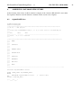
CHANGE RECORD
Issue
1.4
Date
01/06/2006
Affected Paragraphs(s)
All
1.3
10/05/2005
Force Loop Control User Story
1.2
09/04/2005
All
1.1
1.0
04/03/2005
28/02/2005
All
All
Reason/Initiation/Remarks
Some comments added to overview.
Man pages, command definitions,
error definitions and database
structures appendix added.
Added Force Loop mode
requirement
Updated after user requirements
review
First Approach
Creation
4- 1.4
3P6-SDS-ESO-80030-00006
TABLE OF CONTENTS
1.
INTRODUCTION ........................................................................................................................................................ 5
1.1
PURPOSE............................................................................................................................................................. 5
1.2
SCOPE.................................................................................................................................................................. 5
1.3
APPLICABLE DOCUMENTS............................................................................................................................. 5
1.4
REFERENCE DOCUMENTS.............................................................................................................................. 5
1.5
ABBREVIATIONS AND ACRONYMS ............................................................................................................. 6
1.6
STYLISTIC CONVENTIONS ............................................................................................................................. 6
2. OVERVIEW ................................................................................................................................................................. 7
2.1
Actors.................................................................................................................................................................... 8
2.1.1
Inclinometer Acquisition Drive .................................................................................................................... 8
2.1.2
Pressure Acquisition Drive ........................................................................................................................... 8
2.1.3
Pressure Setting Drive................................................................................................................................... 8
2.1.4
VLT Standard Packages................................................................................................................................ 8
2.1.5
Human Actors ............................................................................................................................................... 9
3. ARCHITECTURE ...................................................................................................................................................... 10
3.1
WS Architecture ................................................................................................................................................. 10
3.1.1
User Stories................................................................................................................................................. 10
•
Status Display User Story ................................................................................................................................... 10
•
Force Loop Control User Story........................................................................................................................... 11
•
Engineering User Interface User Story ............................................................................................................... 11
3.1.2
Class Diagram............................................................................................................................................. 13
3.2
LCU Architecture ............................................................................................................................................... 14
3.2.1
User Stories................................................................................................................................................. 14
•
Air Pad Pressure Regulation User Story ............................................................................................................. 14
•
Lateral Pad Force Control User Story................................................................................................................. 15
3.2.2
Class Diagram............................................................................................................................................. 16
4. APPENDIX A: GRAPHICAL USER INTERFACES................................................................................................ 17
4.1
M1 Main Operations GUI................................................................................................................................... 17
4.2
M1 Engineering GUI .......................................................................................................................................... 18
4.3
M1 Forces and Pressures GUI. ........................................................................................................................... 19
5. APPENDIX B: MAN PAGES .................................................................................................................................... 20
5.1
WS Man Pages.................................................................................................................................................... 20
5.1.1
e3p6m1Control WS Process ....................................................................................................................... 20
5.1.2
e3p6m1CON_STD_COMMANDS Class................................................................................................... 21
5.1.3
e3p6m1CON_MAIN_TASK Class............................................................................................................. 23
SYNOPSIS ............................................................................................................................................................. 23
6. APPENDIX B: COMMAND DEFINITION FILES................................................................................................... 28
6.1
WS CDT File (e3p6m1Control.cdt).................................................................................................................... 28
7. APPENDIX C: ERROR DEFINITION FILES........................................................................................................... 38
7.1
WS Error Definition File. ................................................................................................................................... 38
8. APPENDIX D: DATABASE STRUCTURES ........................................................................................................... 41
8.1
e3p6m1BASE.class............................................................................................................................................. 41
8.2
e3p6m1CONTROL.class .................................................................................................................................... 42
9. APPENDIX F: M1 LATERAL PAD PROJECT SW STATISTICS AND PLANNING ........................................... 43
M1 Lateral Pad Control Design Desc. - 1.4
1.
INTRODUCTION
1.1
PURPOSE
3P6-SDS-ESO-80030-00006
5
This document contains the software design description for M1 Lateral Pad Control of the 3.6m telescope.
The information contained on this document provided the guidelines for the implementation and testing of the
new software associated to the project.
The software design presented here is based at the “ESO 360 M1 Lateral Pad Upgrade” [1] user requirements
and the technical specification of the current system described at “3.6m + CAT Upgrade Lateral Support
System”[2].
This document is oriented to software developers and any other people involved at the 3.6m Lateral Pad
Control project. VLT Common Software, UML and Extreme Programming concepts have been introduced
during the development of this document therefore is highly required that the reader be acquainted with these
topics.
1.2
SCOPE
The present describes the conceptual design of the software contained at e3p6m1 module. The software will
be implemented to run on a WS and an LCU. The WS part of the e3p6m1 module will act as coordinator of
the high level tasks of the system as long as the LCU part will contain the low level control for the M1 lateral
pads software.
1.3
APPLICABLE DOCUMENTS
The following documents, of the exact issue shown, form a part of this document to the extent specified
herein. In the even of conflict between the documents referenced herein and the contents of this document, the
contents of this document shall be considered a superseding requirement.
[1] 3P6-USR-ESO-90400-0002, Issue 1.0, 23/09/2004 --- ESO 360 M1 Lateral Pad Upgrade
[2] 3P6-TRE-ESO-031-004, Issue 1.1, 21/10/1998 --- 3m6 + CAT Upgrade Lateral Support System
1.4
REFERENCE DOCUMENTS
The following documents are referenced in this document.
[3] VLT-PRO-ESO-10000-0228, 1.0 10/03/93 --- VLT Software Programming Standards
[4] VLT-MAN-ESO-17210-0619, 2.1 21/03/2001 -- Central Control Software User Manual
[5] VLT-MAN-ESO-17210-0770, 1.7 30/09/99 -- Extended CCS User Manual
[6] VLT-MAN-ESO-17210-0771, 1.7 30/09/99 -- CCS Event Tool Kit - EVH User Manual
[7] VLT-MAN-ESO-17210-0707, 1.6 30/09/99 -- CCS On Line Database Loader Manual
[8] VLT-MAN-ESO-17210-2252, 1.0 25/10/2000 --- LCU Server Framework User Manual
[9] VLT-MAN-SBI-17210-0001, 3.6 1/3/2001 --- LCU Common Software User Manual
[10]VLT-MAN-ESO-17210-0600, 1.7 02/10/98 --- CCS-LCU/ Motor Control Module - Part I
Application Programmatic & Command Interface User Manual
6- 1.4
1.5
3P6-SDS-ESO-80030-00006
ABBREVIATIONS AND ACRONYMS
.
The following abbreviations and acronyms are used in this document:
1.6
AUTREP
Automatic Reporting System
CCS
Central Control Software
ECCS
Extended Central Control Software
EVH
Event Handler Toolkit
GUI
Graphical User Interface
HW
Hardware
LSM
La Silla Management
LSO
La Silla Observatory
LCU
Local Control Unit
N/A
Not Applicable
OLDB
On-line Database
PC
Personal Computer
SRS
Software Requirements Specifications
SW
Software
TBC
To Be Confirmed
TBD
To Be Defined
TCS
Telescope Control System
VLT
Very Large Telescope
WG
Working Group
WS
WorkStation
STYLISTIC CONVENTIONS
The following styles are used:
Bold
In the text, for commands, filenames, pre-suffixes as they have to be typed.
Italic
In the text, for parts that have to be substituted with the real content before typing.
Teletype
For examples.
<name>
in the examples, for parts that have to be substituted with the real content before typing.
Bold and italic are also used to highlight words.
M1 Lateral Pad Control Design Desc. - 1.4
2.
3P6-SDS-ESO-80030-00006
7
OVERVIEW
The e3p6m1 module shall provide the same functionalities of the current lateral pad control software running
on an old PC located at the cage.
The control system shall measure the force at the 21 lateral and the 33 axial pads.
The theoretical pressure for the 21 lateral pads will be computed as a function of the telescope position.
The current telescope position is taken from an inclinometer installed at the telescope and it is completely
independent from TCS.
The system will apply the pressure over the 18 non-fixed pads.
A close loop between the theoretical and the real forces applied over the pads is highly desired, therefore the
system will compute the theoretical forces to be applied as a function of the telescope position.
The difference between the theoretical forces computed and the real forces measured by the load cells will be
regulated in a close loop.
All configuration values will be stored at the OLDB replacing the ASCII files of the current system.
Operational and engineering GUIs will be developed according to the requirements described at [1]. The most
important information will be available for statistic analysis using AUTREP.
HW safety mechanisms are required to avoid disasters in case of LCU and/or WS failures.
For safety reasons, the system can be operated at normal or degraded modes. Degraded mode will be used
when the pressure measured of one or more pads have a value out of the normal range. The numbers of pads
to be ruled out in degraded mode can be set from the engineering panel. In case of a major numbers of pads
have a wrong pressure value; the telescope cannot be used, because the M1 system will change the telescope
status to error.
8- 1.4
2.1
3P6-SDS-ESO-80030-00006
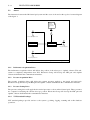
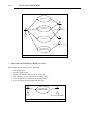
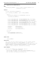
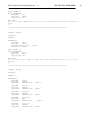
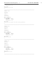
Actors
The interaction between the M1 lateral pad system and the actors is showed at the top-level context diagram
of the figure 1.
Users:
- Operator
- Astronomer
- Support Staff
- etc
User
Inclinometer Acquisition Drive
VLT Standard Packages
e3p6m1
Pressure Setting Drive
Pressure Acquisition Drive
Figure 1: M1 Lateral Pad System Top-level Context Diagram
2.1.1
Inclinometer Acquisition Drive
The inclinometer acquisition driver will deliver the position of the telescope to e3p6m1 software. This subsystem is completely independent from TCS. Electronic Group will develop the HW part and e3p6m1
software shall include the communication interface.
2.1.2
Pressure Acquisition Drive
The pressure acquisition drive will deliver the current pressures applied to the lateral and axial pads.
Electronic Group will develop the HW part and e3p6m1 software shall include the communication interface.
2.1.3
Pressure Setting Drive
The pressure setting drive will apply the theoretical pressures to the non-fixed lateral pads. These pressures
are computed considering the current telescope position. Electronic Group will develop the HW part and
e3p6m1 software shall include the communication interface.
2.1.4
VLT Standard Packages
VLT standard packages provide services to the system e.g. timing, logging, scanning and on-line database
operations.
M1 Lateral Pad Control Design Desc. - 1.4
2.1.5
3P6-SDS-ESO-80030-00006
9
Human Actors
From the software point of view the interaction of human actors with the system is minimal. The major part of
the normal operations will be executed automatically each time the LCU is started. Human interaction is
concentrate at engineering task and system monitoring, i.e. during the commissioning. The interaction
between the actors and the system is through of the graphical user interfaces or CCS messaging system.
10- 1.4
3.
3P6-SDS-ESO-80030-00006
ARCHITECTURE
The software has been divided at real-time and a coordination parts according to the VLT Standards defined at
[3]. The major part of the system shall be implemented as real time application, which be in charge to execute
tasks such as, read the pressures of the pads, read the telescope position of the inclinometer, compute and
apply the theoretical pressures. These applications will be implemented to run on a LCU and using the . The
human interaction with the system will be supported at the WS level. e3p6m1Control process shall be
implemented to support WS commands and e3p6m1Server task for LCU commands.
User Stories, Use Case diagrams and Class diagrams have been developed to describe the WS and LCU
architectures. The description of the commands accepted by the WS and LCU process, the definition of the
classes and the GUIs can be found at the appendix section.
3.1
WS Architecture
The e3p6m1Control process will receive the commands given by the user and will send them to the LCU
server process. A minimal set of user commands will be implemented at WS level due to the interaction
between human users and the system is minimal. Basically, the user command will be reduced to open/close
force loop, set system parameters and the standard commands (init, standby, online).
e3p6m1Control process implementation shall be based on Event Handling Toolkit (EVH) and using services
provided by Extended Central Common Software module (ECCS) whenever possible.
3.1.1
User Stories
The WS user stories have been focused to the interaction between human users and the system. Also the GUIs
have been considered at WS level.
These stories have been taken directly from [1] and a Use Case diagram has been developed to illustrate each
story.
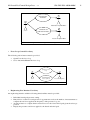
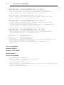
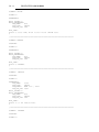
•
Status Display User Story
A status display with the following information must be provided:
•
•
•
•
•
•
•
•
Air pressure regulator status
Air pressure
Inclinometer position
Angle phi0
Telescope Angular Speed
Three mirror position sensor
Telescope HA
Lateral pad force control loop status
M1 Lateral Pad Control Design Desc. - 1.4
3P6-SDS-ESO-80030-00006
Get Inclinometer
Information
Inclinometer Acquisition Drive
Get Lateral and
Axial Pads Information
User
Pressure Acquisition Drive
Figure 2: “Status Display” Use Case Diagram
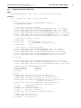
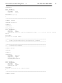
•
Force Loop Control User Story
The following action buttons must be provided:
•
•
Open/Close the force loop
Set to Automatic/Manual the force loop
Open/Close Force
Loop
User
Automatic/Manual
Force Loop Mode
Pressure Setting Drive
Figure 3: “Force Loop Control” Use Case Diagram
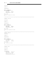
•
Engineering User Interface User Story
An engineering interface with the following functionalities must be provided:
•
•
•
•
Individual lateral pads pressure setting.
Entry field to set the force and pressure loop parameters such as the number of measurements to
compute the real force applied, the frequency of the pressure loop, etc.
An action button to compute the theoretical forces for the 18 non-fixed pads given the telescope
position.
Display the pressures and forces applied to the lateral and axial pads.
11
12- 1.4
3P6-SDS-ESO-80030-00006
Apply Pressure
Set System
Parameter
Pressure Setting Drive
User
Compute Force
Pressure Acquisition Drive
Get Lateral and
Axial Pads Information
Figure 4: “Engineering User Interface” Use Case Diagram
•
Astatic and Lateral Pad Force Display User Story
The following info by pad should be displayed:
•
•
•
•
•
•
Pad identification
Pressure applied (mb)
Pressure measured at electron valve sensor (mb)
Theoretical forces for each lateral and axial pad (kg)
Force measured for each lateral and axial pad (kg)
Force deviation for lateral and axial pads (kg)
Get Lateral and
Axial Pads Information
User
Pressure Acquisition Drive
Figure 5: “Astatic and Lat. Pads Force Display” Use Case Diagram
M1 Lateral Pad Control Design Desc. - 1.4
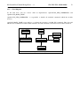
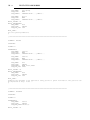
3.1.2
3P6-SDS-ESO-80030-00006
13
Class Diagram
At the WS level only two classes shall be implemented: e3p6m1CON_STD_COMMANDS, and
e3p6m1CON_MAIN_TASK.
e3p6m1CON_STD_COMMANDS
receives.
is responsible to handle all standard commands which the module
e3p6CON_MAIN_TASK is responsible to coordinate the execution of all M1 WS commands. This class will
take the user commands from the standard interface and will send them to the LCU level for their execution.
evhSTD_COMMAND
evhDB_TASK
evhDB_COMMAND
1
e3p6m1CON_STD_COMMAND
e3p6m1CON_MAIN_TASK
evhDB_SYNC
1
eccsERROR_CLASS
Figure 6: WS Class Diagram
1
14- 1.4
3.2
3P6-SDS-ESO-80030-00006
LCU Architecture
As mentioned before, the major part of the M1 lateral pad control software will be developed at LCU level.
The software shall interact with the Lateral and Axial Pad HW, the Inclinometer and the three mirror
displacement sensors.
The LCU e3p6m1Server task shall be implemented using LCU Server Framework (LSF) module. It provides
skeleton implementation to manage standard command and HW devices such as analog and digital devices,
serial communication, etc. The LSF module also allows implementing control software for special devices.
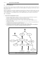
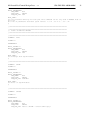
3.2.1
•
User Stories
Air Pad Pressure Regulation User Story
•
•
•
•
•
•
Pressure regulation shall be a function of telescope position given by the inclinometer system. It
should be working all the time with time response lower than 2 seconds.
Pressure regulation in the operational range should be included at TCS general state.
Air pressure should be in the range of 2.8 to 3.2 (bar). If not an alarm must be triggered to move
telescope to the zenith.
Check that every pad has a pressure value inside the range allowed, otherwise, the system will be set
to degraded mode or a telescope error will be released.
Air pressure lower than 2.0 (bar) should also activate the mirror clamps system.
Constant air pressure should be applied to the pads either after a program crash or during HW/SW
start-up. In the first case, last pressure setting must kept until system re-boot.
Figure 7: “Air Pressure Regulation” Use Case Diagram
M1 Lateral Pad Control Design Desc. - 1.4
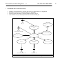
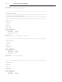
•
3P6-SDS-ESO-80030-00006
Lateral Pad Force Control User Story
•
•
•
•
Number of measurements to compute the real forces applied must be configurable.
Frequency of force loop corrections must be configurable.
Forces deviation should be computed with a precision of 0.1%
The maximal force by lateral pad should be lower that 24525 (N).
User
Trigger SW Alarm
O pen/Close Force
Loop
«extends»
«extends»
Lateral and Axial Pad HW
«uses»
Check Force Range
«uses»
Com pute Forces
Set Force
«uses»
«uses»
G et Force
G et Telescope
Position
Lateral and Axial Pad H W
Inclinom eter HW
«uses»
Figure 8: “Lateral Pad Force Control” Use Case Diagram
Force to Pressure
15
16- 1.4
3.2.2
3P6-SDS-ESO-80030-00006
Class Diagram
At LCU level 9 classes will be implemented: e3p6m1Server, e3p6m1Standard, e3p6m1TaskDev,
e3p6m1ControlLoop, e3p6m1ForceLoop, e3p6m1PositionLoop, e3p6m1Monitor, e3p6m1Signal and
e3p6m1Serial.
e3p6m1Standard is responsible to handle all standard commands which module receives. e3p6m1Server is in
charge to coordinate the execution of all module specified commands.
e3p6m1PositionLoop will implement the LCU tasks for applying to the pneumatic pads the pressure
corresponding to the theoretical forces calculated as a function of the telescope position.
e3p6m1ForceLoop will control the pressure applied to the pneumatic pads, the correction will be obtained as a
function of the differences between the theoretical forces and the real forces measured at the load cells.
e3p6m1ControlLoop is an abstract class which has been obtained from the application of the “Dependency
Inversion Design Pattern Principle”. e3p6m1TaskDev is the base class for the implementation of LCU task
applications.
e3p6m1Serial and e3p6m1Signal are the class which provide the software routines to read and write from/to a
serial and analog or digital interfaces. These classes will be used to communicate e3p6m1 software with the
inclinometer, the lateral pads HW and the displacement sensors.
Figure 8: LCU Class Diagram
M1 Lateral Pad Control Design Desc. - 1.4
4.
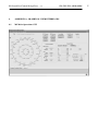
APPENDIX A: GRAPHICAL USER INTERFACES
4.1
M1 Main Operations GUI
3P6-SDS-ESO-80030-00006
17
18- 1.4
4.2
3P6-SDS-ESO-80030-00006
M1 Engineering GUI
M1 Lateral Pad Control Design Desc. - 1.4
4.3
M1 Forces and Pressures GUI.
3P6-SDS-ESO-80030-00006
19
20- 1.4
5.
3P6-SDS-ESO-80030-00006
APPENDIX B: MAN PAGES
At the moment of the release of this document, both parts of the software (WS and LCU) were under
development. Therefore, the information contained on this section is not complete.
5.1
WS Man Pages
5.1.1
e3p6m1Control WS Process
NAME
e3p6m1Control - 3.6m Telescope M1 Lateral Pads Workstation Control Process
Component of the M1 TCS Functional Module
to receive and handle all user commands
SYNOPSIS
e3p6m1Control [-r dbRoot] [-n processName]
DESCRIPTION
The M1 Control Process receives all M1 user commands,
process some of them and distributes other commands to the M1 LCUs
involved at the lateral pad control system.
The optional argument dbRoot is the root point of the TCS packet
DB branch. If omitted it is defaulted to value of the TCS_DBPOINT
environment variable or, if even this not defined, hard-coded
to ":Appl_data:TCS".
The M1 Control Process Workstation sub-branch root point is built
appending the point name "e3p6m1" to the TCS branch name.
The default database point for M1 Control Process for Workstation
is then: ":Appl_data:TCS:e3p6m1".
The optional argument processName is the name under which the
process' instance registers with the CCS and hence the destination
process name for commands to it. If omitted, the instance registers
with CCS with its UNIX process name, as passed by the shell in argv[0].
FILES
ENVIRONMENT
TCS_DBPOINT specifies the root point of the TCS database branch.
COMMANDS
RETURN VALUES
0 if everything OK
1 on error
CAUTIONS
EXAMPLES
SEE ALSO
BUGS
M1 Lateral Pad Control Design Desc. - 1.4
5.1.2
3P6-SDS-ESO-80030-00006
e3p6m1CON_STD_COMMANDS Class
NAME
e3p6m1CON_STD_COMMANDS - Class to handle standard commands in the
e3p6m1Control process.
SYNOPSIS
#include "e3p6m1CON_STD_COMMANDS.h"
class e3p6m1CON_STD_COMMANDS : public evhSTD_COMMANDS
{
public:
e3p6m1CON_STD_COMMANDS(const dbSYMADDRESS dbPoint);
~e3p6m1CON_STD_COMMANDS();
virtual
virtual
virtual
virtual
virtual
virtual
virtual
virtual
evhCB_COMPL_STAT
evhCB_COMPL_STAT
evhCB_COMPL_STAT
evhCB_COMPL_STAT
evhCB_COMPL_STAT
evhCB_COMPL_STAT
evhCB_COMPL_STAT
evhCB_COMPL_STAT
vltINT32
const char*
vltINT32
const char*
StateCB(msgMESSAGE &msg, void *udata);
StatusCB(msgMESSAGE &msg, void *udata);
OffCB(msgMESSAGE &msg, void *udata);
SelfTestCB(msgMESSAGE &msg, void *udata);
TestCB(msgMESSAGE &msg, void *udata);
SimulatCB(msgMESSAGE &msg, void *udata);
StopSimCB(msgMESSAGE &msg, void *udata);
VerboseCB(msgMESSAGE &msg, void *udata);
GlobalState();
GlobalStateName();
GlobalSubState();
GlobalSubStateName();
protected:
private:
const dbSYMADDRESS
const dbSYMADDRESS
dbBasePoint;
dbControlPoint;
};
PARENT CLASS
evhSTD_COMMANDS
DESCRIPTION
This class overload the default behaviour for some standard commands
implemented by the base class evhSTD_COMMANDS, in order to meet
the specific requirements of the e3p6m1Control process. Also, some of the
standard commands are implemented here, in exactly the same way as the
default behaviour (taken from evhSTD_COMMMANDS), to allow for easier
addition of special behaviour, should this be necessary!
PUBLIC METHODS
e3p6m1CON_STD_COMMANDS(const dbSYMADDRESS dbPoint,
const char *version);
Initialize the name state table using e3p6m1StateNameMap and
load the symbolic address of its parent point, where it is assumed
that the "state" and "substate" attributes are.
21
22- 1.4
3P6-SDS-ESO-80030-00006
evhCB_COMPL_STAT StateCB(msgMESSAGE &msg, void *udata);
evhCB_COMPL_STAT StatusCB(msgMESSAGE &msg, void *udata);
These two callbacks are used for the STATE and STATUS commands.
They read the value of the "state" and "substate" attributes in the
control database point and format the reply to be sent.
evhCB_COMPL_STAT OffCB(msgMESSAGE &msg, void *udata);
In this simple first implementation the command just set the local
state of e3p6m1Control to the requested value.
evhCB_COMPL_STAT SelfTestCB(msgMESSAGE &msg, void *udata);
evhCB_COMPL_STAT TestCB(msgMESSAGE &msg, void *udata);
In this simple implementation the commands just send an OK message
to the originator, like in the base class.
They have been overloaded here just to make easier to implement later
a real behaviour, performing really some test.
evhCB_COMPL_STAT SimulatCB(msgMESSAGE &msg, void *udata);
evhCB_COMPL_STAT StopSimCB(msgMESSAGE &msg, void *udata);
evhCB_COMPL_STAT VerboseCB(msgMESSAGE &msg, void *udata);
This commands work locally as the base class, setting the database
corresponding variable to the requested value.
vltINT32
GlobalState();
const char*
GlobalStateName();
vltINT32
GlobalSubState();
const char*
GlobalSubStateName();
These methods return the index value or the string corresponding to the
global state and substate of the module.
They read these value from the attributes that must be in the
parent point.
PUBLIC DATA MEMBERS
PROTECTED METHODS
PROTECTED DATA MEMBERS
PRIVATE METHODS
PRIVATE DATA MEMBERS
const dbSYMADDRESS dbBasePoint;
Symbolic address of the database parent point
It is set in the constructor.
const dbSYMADDRESS dbControlPoint;
Symbolic address of the database control point, which is assumed have state
points of application.
It is set in the constructor.
M1 Lateral Pad Control Design Desc. - 1.4
5.1.3
3P6-SDS-ESO-80030-00006
e3p6m1CON_MAIN_TASK Class
NAME
e3p6m1CON_MAIN_TASK - Main class for the e3p6m1Control program
SYNOPSIS
class e3p6m1CON_MAIN_TASK : public evhDB_TASK
{
public:
e3p6m1CON_MAIN_TASK(const dbSYMADDRESS &dbPoint);
~e3p6m1CON_MAIN_TASK();
// Callbacks for public commands
virtual evhCB_COMPL_STAT M1SetLogCB(msgMESSAGE &msg, void *udata);
virtual evhCB_COMPL_STAT M1SetModeCB(msgMESSAGE &msg, void *udata);
virtual evhCB_COMPL_STAT M1SetLoopCB(msgMESSAGE &msg, void *udata);
virtual evhCB_COMPL_STAT M1ConfParamsCB(msgMESSAGE &msg, void *udata);
virtual evhCB_COMPL_STAT M1CalcPressCB(msgMESSAGE &msg, void *udata);
virtual evhCB_COMPL_STAT M1SetPressCB(msgMESSAGE &msg, void *udata);
// Callbacks for public commands
ccsCOMPL_STAT
Recover();
ccsCOMPL_STAT
Init(evhCALLBACK *okCb = NULL,
evhCALLBACK *errorCb = NULL);
ccsCOMPL_STAT
Init();
// Overloading of inherited commands
virtual evhCB_COMPL_STAT ExitCB(msgMESSAGE &msg, void *udata);
virtual evhCB_COMPL_STAT InitCB(msgMESSAGE &msg, void *udata);
virtual evhCB_COMPL_STAT OnlineCB(msgMESSAGE &msg, void *udata);
virtual evhCB_COMPL_STAT StandbyCB(msgMESSAGE &msg, void *udata);
virtual evhCB_COMPL_STAT StopCB(msgMESSAGE &msg, void *udata);
protected:
virtual evhCB_COMPL_STAT M1CmdOKCB(msgMESSAGE &msg, void *udata);
virtual evhCB_COMPL_STAT M1CmdErrorCB(msgMESSAGE &msg, void *udata);
virtual evhCB_COMPL_STAT GeneralErrorCB(msgMESSAGE &msg, void *udata);
ccsCOMPL_STAT ExpandCmd(msgMESSAGE &msg);
evhDB_CMD_SERIAL
*M1Cmd;
evhDB_CMD_SERIAL
*M1TCSCmd;
e3p6m1LOG
*log;
private:
ccsCOMPL_STAT
ccsCOMPL_STAT
ccsCOMPL_STAT
ccsCOMPL_STAT
SubState(const vltINT32 &substate);
SetStateString(const vltINT32 &state);
SetSubStateString(const vltINT32 &state);
CheckSubstate(msgMESSAGE &msg,vltINT32 substate,
vltINT32 *valid=NULL);
ccsCOMPL_STAT Checkstate(msgMESSAGE &msg,vltINT32 state,
vltINT32 valid=NULL);
vltINT32
ReadModSubState();
vltINT32
ReadModState();
ccsCOMPL_STAT SaveCurrentSubState();
vltINT32
ReadPreviousSubState();
ccsCOMPL_STAT PreviousSubState(vltINT32 substate);
ccsCOMPL_STAT ErrorState();
ccsCOMPL_STAT ResetFocusSync();
vltLOGICAL
ErrorStatus();
23
24- 1.4
3P6-SDS-ESO-80030-00006
dbSYMADDRESS
dbSYMADDRESS
dbSYMADDRESS
msgMESSAGE
msgMESSAGE
vltLOGICAL
vltINT32
dbBasePoint;
dbDataPoint;
dbControlPoint;
M1CmdMsg;
M1CmdTCSMsg;
loggingFlag;
M1CmdTimeout;
vltINT32
vltINT32
errorState;
previousState;
};
PARENT CLASS
evhDB_TASK
DESCRIPTION
An instance of this class is the core of the e3p6m1Control
program, which is the main workstation process for the M1
Lateral Pad Control System. All commands for the
e3p6m1 module are received by this process.
Some of the commands are processed and then distributed to M1 LCU
which performs the Lateral Pad control loop,
When the object is created it registers the callbacks for all
the commands. Whenever one of these commands is received, the
corresponding callback is called.
The class uses other EVH objects to handle commands.
PUBLIC METHODS
e3p6m1CON_MAIN_TASK(const dbSYMADDRESS dbPoint);
The constructor receives as parameter the symbolic address
of the online database support point for the object, i.e.
the point where the object can find configuration and private
run time values. It initialises some internal data, installs
all command callbacks, creates the co-operating objects.
~e3p6m1CON_MAIN_TASK();
The destructor de-registers all callbacks and deletes all
objects created.
virtual evhCB_COMPL_STAT M1SetLogCB(msgMESSAGE &msg,
void *udata);
This callback is called when M1LOG command is received.
It sets logging on/off using Logging On/Off methods of
e3p6m1LOG class.
virtual evhCB_COMPL_STAT M1SetModeCB(msgMESSAGE &msg,
void *udata);
This callback is called when M1SETM command is received.
It will be used to change the Loop control mode to AUTOMATIC
or MANUAL. MANUAL mode allows to send pressure values at every non-fixed
lateral pad from the engineering panel.
virtual evhCB_COMPL_STAT M1SetLoopCB(msgMESSAGE &msg,
void *udata);
This callback is called when M1SETL command is received.
It will be used to change the loop mode to OPEN or CLOSE loop.
CLOSE loop introduces corrections to the theoretical forces applied.
M1 Lateral Pad Control Design Desc. - 1.4
3P6-SDS-ESO-80030-00006
25
virtual evhCB_COMPL_STAT M1ConfParamsCB(msgMESSAGE &msg,
void *udata);
This callback is called when M1CONF command is received.
It performs the set of all M1 configurations parameters such as
the number of pads to be ruled out at degraded mode, the number
of measurements to compute the position, pressures and
forces applied over the pads.
virtual evhCB_COMPL_STAT M1CalcPressCB(msgMESSAGE &msg,
void *udata);
This callback is called when M1CALC command is received.
It performs the computation of the pressures to be applied at
every pad for a given telescope position. The position can be expressed
at volts or deg. This command only computes the theoretical values
but they will not be applied.
virtual evhCB_COMPL_STAT M1SetPressCB(msgMESSAGE &msg,
void *udata);
This callback is called when M1SETPR command is received.
It will be used to set a theoretical pressure for every pad.
The format of this command parameters should be <pad value> i.e
1 0.3 2 0.5 3 0.1.... 18 0.9
virtual evhCB_COMPL_STAT ExitCB(msgMESSAGE &msg,
void *udata);
This callback is called when the EXIT command is received.
This callback sends the final reply, and thus causes the
process to really exit.
virtual evhCB_COMPL_STAT InitCB(msgMESSAGE &msg, void *udata);
This callback is called when the INIT command is received.
It calls Init to overload the Init method inherited from the
base class.
virtual evhCB_COMPL_STAT OnlineCB(msgMESSAGE &msg, void *udata);
This callback is called when the ONLINE command is received.
If the module is already ONLINE, sends back a reply and returns,
otherwise it behaves like init.
Not implemented yet.
ccsCOMPL_STAT
Init()
This method overloads the Init method inherited from the
base class. It reads configuration parameters from the database, and initialises some internal structures and data. It
also initalize co-operating objects and sets the state of the
process e3p6m1Control to ONLINE.
ccsCOMPL_STAT
Recover();
This method is used to try to recover from a severe error.
The attempt is logged.
First, the state is set to ERROR, so that interested processes
can be notified.
The Init() method is called to reinitialize everything.
PUBLIC DATA MEMBERS
None.
26- 1.4
3P6-SDS-ESO-80030-00006
PROTECTED METHODS
virtual evhCB_COMPL_STAT GeneralErrorCB(msgMESSAGE &msg, void *udata);
Co-operating objects can trigger this callback when error has
been occured during their action. The module state is set to error.
virtual evhCB_COMPL_STAT M1CmdOKCB(msgMESSAGE &msg, void *udata);
This callback is called when a M1 LCU command has
been performed successfully. No replys is sent back, because
command handlers had send OK reply already.
virtual evhCB_COMPL_STAT M1CmdErrorCB(msgMESSAGE &msg, void *udata);
This callback is executed on error or timeout occured when
executing M1 LCU command. No replys is sent back, because M1 command
has been sent by main task, not user. However, the module state is
set to error state.
PROTECTED DATA MEMBERS
evhDB_CMD_SERIAL
evhDB_CMD_SERIAL
e3p6m1LOG
*M1Cmd;
*M1TCSCmd;
*log
M1 LCU command object
TCS command object
logging object
PRIVATE METHODS
ccsCOMPL_STAT SubState(const vltINT32 &substate);
Sets substate of module to OLDB.
ccsCOMPL_STAT SetStateString(const vltINT32 &state);
Sets state string of the module to OLDB.
ccsCOMPL_STAT SetSubStateString(const vltINT32 &state);
Sets substate string of the module to OLDB.
vltINT32 ReadModState();
This method reads and returns the state of the e3p6m1 module
from OLDB.
vltINT32 ReadModSubstate();
This method reads and returns the substate of the e3p6m1 module
from OLDB.
ccsCOMPL_STAT ErrorState();
This method sets module to error state. It populates the error
state also to co-operating classes if populate is set TRUE.
PRIVATE DATA MEMBERS
dbSYMADDRESS
dbSYMADDRESS
dbBasePoint
dbDataPoint
class OLDB root point
OLDB point where is saved configuration data
of objects
OLDB point where is saved control data
of objects
dbSYMADDRESS
dbControlPoint
msgMESSAGE
msgMESSAGE
vltLOGICAL
vltINT32
M1CmdMsg;
M1CmdTCSMsg;
loggingFlag;
M1CmdTimeout;
message
message
logging
timeout
presets
vltINT32
errorState
error state of the module
to construct for M1 LCU command
to construct for telescope presets
status
of M1 LCU command and telescope
M1 Lateral Pad Control Design Desc. - 1.4
3P6-SDS-ESO-80030-00006
ON-LINE DATABASE
The class shares an instance of the e3p6m1CONTROL class with
e3p6m1CON_STD_COMMANDS
SEE ALSO
EVH(5), evhDB_TASK(4), evhDB_CMD_SERIAL(4), evhDB_SYNC(4),
27
28- 1.4
6.
3P6-SDS-ESO-80030-00006
APPENDIX B: COMMAND DEFINITION FILES
At the moment of the release of this document, both parts of the software (WS and LCU) were under
development. Therefore, the information contained on this section is not complete.
6.1
WS CDT File (e3p6m1Control.cdt)
//----------------------------------------------------------------------------// ESO VLT
3.6m f/8 M2 WS Control Software
//----------------------------------------------------------------------------// "@(#) $Id: e3p6m1Control.cdt,v 0.6+ 2006/05/11 16:17:02 vltsccm Exp $"
//----------------------------------------------------------------------------// who
when
what
// -------- -------- ---------------------------------------------// rsoto
2006-05-06 created.
//
//----------------------------------------------------------------------------//**********************************************************************
PUBLIC_COMMANDS
//======================================================================
// Module specified public commands
//======================================================================
//======================================================================
COMMAND=
M1LOG
SYNONYMS=
FORMAT= A
PARAMETERS=
PAR_NAME=
PAR_TYPE=
PAR_RANGE=
PAR_DEF_VAL=
onOff
STRING
ENUM "On" , "Off"
"Off"
REPLY_FORMAT = A
REPLY_PARAMETERS=
PAR_NAME=
done
PAR_TYPE=
STRING
PAR_DEF_VAL= "OK"
HELP_TEXT=
Set logging on/off.
@
//======================================================================
COMMAND=
M1SETM
SYNONYMS=
FORMAT= A
PARAMETERS=
PAR_NAME=
value
PAR_TYPE=
STRING
PAR_RANGE= ENUM "AUTO" , "MANUAL"
PAR_DEF_VAL= "AUTO"
M1 Lateral Pad Control Design Desc. - 1.4
3P6-SDS-ESO-80030-00006
REPLY_FORMAT = A
REPLY_PARAMETERS=
PAR_NAME=
done
PAR_TYPE=
STRING
PAR_DEF_VAL= "OK"
HELP_TEXT=
Set the loop mode, MANUAL mode allows to enter pressures manually from the engineering
panel.
@
//======================================================================
COMMAND=
M1SETL
SYNONYMS=
FORMAT= A
PARAMETERS=
PAR_NAME=
value
PAR_TYPE=
STRING
PAR_RANGE= ENUM "OPEN" , "CLOSE"
PAR_DEF_VAL= "OPEN"
REPLY_FORMAT = A
REPLY_PARAMETERS=
PAR_NAME=
done
PAR_TYPE=
STRING
PAR_DEF_VAL= "OK"
HELP_TEXT=
Set the control loop to OPEN or CLOSE. CLOSE loop introduces corrections to the forces
applied.
@
//======================================================================
COMMAND=
M1CONF
SYNONYMS=
FORMAT= A
PARAMETERS=
PAR_NAME=
PAR_TYPE=
PAR_RANGE=
padDis
INTEGER
INTERVAL MIN= 0 ;MAX=18
PAR_NAME=
PAR_TYPE=
PAR_RANGE=
meanPos
INTEGER
INTERVAL MIN= 0 ;MAX=5
PAR_NAME=
PAR_TYPE=
PAR_RANGE=
meanPress
INTEGER
INTERVAL MIN= 0 ;MAX=5
PAR_NAME=
PAR_TYPE=
PAR_RANGE=
prLoopFreq
REAL
INTERVAL MIN= 0.0 ;MAX=10.0
PAR_NAME=
PAR_TYPE=
PAR_RANGE=
meanForce
INTEGER
INTERVAL MIN= 0 ;MAX=5
29
30- 1.4
3P6-SDS-ESO-80030-00006
PAR_NAME=
PAR_TYPE=
PAR_RANGE=
frLoopFreq
REAL
INTERVAL MIN= 0.0 ;MAX=10.0
PAR_NAME=
PAR_TYPE=
PAR_RANGE=
kForce
REAL
INTERVAL MIN= 0.0 ;MAX=1.0
REPLY_FORMAT = A
REPLY_PARAMETERS=
PAR_NAME=
done
PAR_TYPE=
STRING
PAR_DEF_VAL= "OK"
HELP_TEXT=
Set the system parameters.
@
//======================================================================
COMMAND=
M1CALC
SYNONYMS=
FORMAT= A
PARAMETERS=
PAR_NAME=
PAR_TYPE=
PAR_RANGE=
nsValue
REAL
INTERVAL MIN= 0.0 ;MAX=100.0
PAR_NAME=
PAR_TYPE=
PAR_RANGE=
ewValue
REAL
INTERVAL MIN= 0.0 ;MAX=100.0
PAR_NAME=
PAR_TYPE=
PAR_RANGE=
PAR_DEF_VAL=
unit
STRING
ENUM "VOL","DEG"
"DEG"
REPLY_FORMAT = A
REPLY_PARAMETERS=
PAR_NAME=
done
PAR_TYPE=
STRING
PAR_DEF_VAL= "OK"
HELP_TEXT=
Computes the pressure to be applied at every pad for a given inclination. The position can
be expressed at deg o volts .
@
//======================================================================
COMMAND=
M1SETPR
SYNONYMS=
FORMAT= A
PARAMETERS=
PAR_NAME=
values
PAR_TYPE=
STRING
PAR_MAX_REPETITION=999
REPLY_FORMAT = A
M1 Lateral Pad Control Design Desc. - 1.4
3P6-SDS-ESO-80030-00006
31
REPLY_PARAMETERS=
PAR_NAME=
done
PAR_TYPE=
STRING
PAR_DEF_VAL= "OK"
HELP_TEXT=
Set the pressures manually for each pad. This commands can be only used in MANUAL mode of
the loop.
The list of parameters should be <pad> <value>. i.e "1 0.23 2 2.0...18 0.2"
@
//======================================================================
//======================================================================
// Public Standard commands
//======================================================================
//======================================================================
COMMAND=
PING
FORMAT= A
PARAMETERS=
REPLY_FORMAT= A
REPLY_PARAMETERS=
PAR_NAME=
done
PAR_TYPE=
STRING
PAR_DEF_VAL= "OK"
HELP_TEXT=
Get lifesign from e3p6m1 module.
@
//======================================================================
COMMAND=
STATE
FORMAT= A
PARAMETERS=
REPLY_FORMAT= A
REPLY_PARAMETERS=
PAR_NAME=
done
PAR_TYPE=
STRING
PAR_DEF_VAL= "ONLINE"
HELP_TEXT=
Get state of e3p6m1 module.
@
//======================================================================
COMMAND=
STATUS
FORMAT= A
PARAMETERS=
REPLY_FORMAT= A
REPLY_PARAMETERS=
PAR_NAME=
done
PAR_TYPE=
STRING
PAR_DEF_VAL= "State: ONLINE - Default CMD reply"
32- 1.4
3P6-SDS-ESO-80030-00006
HELP_TEXT=
Get complete status of e3p6m1 module.
@
//**********************************************************************
MAINTENANCE_COMMANDS
//======================================================================
// Maintenance Standard commands
//======================================================================
//======================================================================
COMMAND=
STOP
SYNONYMS=
FORMAT= A
PARAMETERS=
REPLY_FORMAT = A
REPLY_PARAMETERS=
PAR_NAME=
done
PAR_TYPE=
STRING
PAR_DEF_VAL= "OK"
HELP_TEXT=
Stop any action of e3p6m1Control process.
@
//======================================================================
COMMAND= BREAK
SYNONYMS=
FORMAT= A
PARAMETERS=
REPLY_FORMAT= A
REPLY_PARAMETERS=
PAR_NAME=
done
PAR_TYPE=
STRING
PAR_DEF_VAL= "OK"
HELP_TEXT=
Stop action on the e3p6m1Control.
@
//======================================================================
COMMAND= EXIT
SYNONYMS=
FORMAT= A
PARAMETERS=
REPLY_FORMAT= A
REPLY_PARAMETERS=
PAR_NAME=
done
PAR_TYPE=
STRING
M1 Lateral Pad Control Design Desc. - 1.4
3P6-SDS-ESO-80030-00006
PAR_DEF_VAL= "OK"
HELP_TEXT=
Terminate the process.
@
//======================================================================
COMMAND= INIT
SYNONYMS=
FORMAT= A
PARAMETERS=
REPLY_FORMAT= A
REPLY_PARAMETERS=
PAR_NAME=
done
PAR_TYPE=
STRING
PAR_DEF_VAL= "OK"
HELP_TEXT=
Initialize the software and read config parameters.
@
//======================================================================
COMMAND= KILL
SYNONYMS=
FORMAT= A
PARAMETERS=
REPLY_FORMAT= A
REPLY_PARAMETERS=
PAR_NAME=
done
PAR_TYPE=
STRING
PAR_DEF_VAL= "OK"
HELP_TEXT=
Kill the process.
@
//======================================================================
COMMAND= OFF
SYNONYMS=
FORMAT= A
PARAMETERS=
REPLY_FORMAT= A
REPLY_PARAMETERS=
PAR_NAME=
done
PAR_TYPE=
STRING
PAR_DEF_VAL= "OK"
HELP_TEXT=
Switch to OFF state.
@
//======================================================================
33
34- 1.4
3P6-SDS-ESO-80030-00006
COMMAND= ONLINE
FORMAT= A
PARAMETERS=
REPLY_FORMAT= A
REPLY_PARAMETERS=
PAR_NAME=
done
PAR_TYPE=
STRING
PAR_DEF_VAL= "OK"
HELP_TEXT=
Switch to state IDLE, which is the initial ONLINE state.
@
//======================================================================
COMMAND= STANDBY
SYNONYMS=
FORMAT= A
PARAMETERS=
REPLY_FORMAT= A
REPLY_PARAMETERS=
PAR_NAME=
done
PAR_TYPE=
STRING
PAR_DEF_VAL= "OK"
HELP_TEXT=
Switch to STANDBY.
@
//======================================================================
COMMAND=
VERBOSE
SYNONYMS=
FORMAT= A
PARAMETERS=
PAR_NAME=
PAR_TYPE=
PAR_RANGE=
PAR_DEF_VAL=
onOff
STRING
ENUM "On" , "Off"
"Off"
REPLY_FORMAT= A
REPLY_PARAMETERS=
PAR_NAME=
done
PAR_TYPE=
STRING
PAR_DEF_VAL= "OK"
HELP_TEXT=
Switch on or off verbose mode.
@
//======================================================================
COMMAND=
SYNONYMS=
FORMAT= A
GETVERB
M1 Lateral Pad Control Design Desc. - 1.4
3P6-SDS-ESO-80030-00006
35
PARAMETERS=
REPLY_FORMAT= A
REPLY_PARAMETERS=
PAR_NAME=
onOff
PAR_TYPE=
STRING
HELP_TEXT=
Get the verbose mode.
@
//======================================================================
COMMAND=
VERSION
SYNONYMS= GetVersion
FORMAT= A
PARAMETERS=
REPLY_FORMAT= A
REPLY_PARAMETERS=
PAR_NAME=
done
PAR_TYPE=
STRING
PAR_DEF_VAL= "Version: @(#) $Id: e3p6m1Control.cdt,v 0.6+ 2006/05/11 16:17:02 vltsccm
Exp $"
HELP_TEXT=
Get version of e3p6m1 module.
@
//======================================================================
//
Module specified Maintenance and engineering commands
//======================================================================
//======================================================================
//
Standard test commands
//======================================================================
COMMAND= SELFTST
SYNONYMS=
FORMAT= A
PARAMETERS=
PAR_NAME=
function
PAR_TYPE=
STRING
PAR_OPTIONAL= YES
PAR_MAX_REPETITION=999
REPLY_FORMAT= A
REPLY_PARAMETERS=
PAR_NAME=
done
PAR_TYPE=
STRING
PAR_DEF_VAL= "OK"
HELP_TEXT=
Perform a self-test of the software module.
@
//======================================================================
COMMAND= SIMULAT
36- 1.4
3P6-SDS-ESO-80030-00006
SYNONYMS=
FORMAT= A
PARAMETERS=
REPLY_FORMAT= A
REPLY_PARAMETERS=
PAR_NAME=
done
PAR_TYPE=
STRING
PAR_DEF_VAL= "OK"
HELP_TEXT=
Switch on simulation mode.
@
//======================================================================
COMMAND= STOPSIM
SYNONYMS=
FORMAT= A
PARAMETERS=
REPLY_FORMAT= A
REPLY_PARAMETERS=
PAR_NAME=
done
PAR_TYPE=
STRING
PAR_DEF_VAL= "OK"
HELP_TEXT=
Switch off simulation mode.
@
//======================================================================
COMMAND= GETSIM
SYNONYMS=
FORMAT= A
PARAMETERS=
REPLY_FORMAT= A
REPLY_PARAMETERS=
PAR_NAME=
OnOff
PAR_TYPE=
STRING
HELP_TEXT=
Get simulation mode.
@
//======================================================================
COMMAND= TEST
SYNONYMS=
FORMAT= A
PARAMETERS=
PAR_NAME=
function
PAR_TYPE=
STRING
PAR_OPTIONAL= YES
PAR_MAX_REPETITION=999
M1 Lateral Pad Control Design Desc. - 1.4
REPLY_FORMAT= A
REPLY_PARAMETERS=
PAR_NAME=
done
PAR_TYPE=
STRING
PAR_DEF_VAL= "OK"
HELP_TEXT=
Perform a complete test of the software module.
@
3P6-SDS-ESO-80030-00006
37
38- 1.4
7.
3P6-SDS-ESO-80030-00006
APPENDIX C: ERROR DEFINITION FILES
At the moment of the release of this document, both parts of the software (WS and LCU) were under
development. Therefore, the information contained on this section is not complete.
7.1
WS Error Definition File.
# Version Id. is specified at the end of the file
#
# Error Definition File
Created on May 24 22:57:01 2006
#
# This file has been generated by a utility
#
# !!!!!!!!!!! DO NOT MANUALLY EDIT THIS FILE !!!!!!!!!!!
#
###########################################################
#define e3p6m1ErrOffset 0
1 F e3p6m1ErrOffset
e3p6m1ERR_DB_WRITE : Failed to write database
noHelp
2 F e3p6m1ErrOffset
e3p6m1ERR_DB_READ : Failed to read from database
noHelp
3 S e3p6m1ErrOffset
e3p6m1ERR_CMD_FAILED : Cmd: %.30s Buffer:%.30
noHelp
4 W e3p6m1ErrOffset
e3p6m1ERR_CMD_TIMEOUT : Cmd: %.30s Buffer:%.30
noHelp
5 S e3p6m1ErrOffset
e3p6m1ERR_SEND_REPLY : Error sending reply to originator
noHelp
6 S e3p6m1ErrOffset
e3p6m1ERR_SEND_OK_REPLY : Command completed, but cannot send reply to originator
noHelp
7 S e3p6m1ErrOffset
e3p6m1ERR_SEND_ERROR_REPLY : Command failed, but cannot send reply to originator
noHelp
8 W e3p6m1ErrOffset
e3p6m1ERR_NOTALLOWED_IN_STATE : Command failed: not allowed in current state: %.20s
noHelp
9 W e3p6m1ErrOffset
e3p6m1ERR_NEW_COMMAND_RECEIVED : Command failed: aborted because new command received
noHelp
10 F e3p6m1ErrOffset
e3p6m1ERR_INIT : Error during Init(): %.80s
noHelp
11 W e3p6m1ErrOffset
e3p6m1ERR_INIT_RECEIVED : Command failed: INIT command received
noHelp
12 F e3p6m1ErrOffset
e3p6m1ERR_FATAL : Fatal error in %.20s. Trying to recover
noHelp
13 F e3p6m1ErrOffset
e3p6m1ERR_RECOVER : Fatal error in %.20s. Cannot recover. Application aborted
noHelp
14 W e3p6m1ErrOffset
e3p6m1ERR_NOT_TRACKING : Command rejected. Telescope is not TRACKING
noHelp
15 W e3p6m1ErrOffset
e3p6m1ERR_NOT_IDLE : Command rejected. Module is not IDLE. Cmd: %.20s
noHelp
16 W e3p6m1ErrOffset
e3p6m1ERR_UNEXPECTED_SUBSTATE : Module is in an unexpected substate: %.20s
M1 Lateral Pad Control Design Desc. - 1.4
3P6-SDS-ESO-80030-00006
noHelp
17 S e3p6m1ErrOffset
e3p6m1ERR_EXPAND_CMD_BUFFER : Error in command parameters detected
noHelp
18 W e3p6m1ErrOffset
e3p6m1ERR_TOO_MANY_ERRORS : Too many consecutive errors. Stop logging
noHelp
19 S e3p6m1ErrOffset
e3p6m1ERR_OPEN_FILE : Could not open file %.50s
noHelp
20 S e3p6m1ErrOffset
e3p6m1ERR_APPEND_FILE : Could not append to file %.50s
noHelp
21 W e3p6m1ErrOffset
e3p6m1ERR_NOT_ONLINE : Command rejected. Module is not ONLINE. Cmd: %.20s
noHelp
22 S e3p6m1ErrOffset
e3p6m1ERR_START_TIMER : Could not start timer for cyclical corrections.
noHelp
23 F e3p6m1ErrOffset
e3p6m1ERR_INIT_RETRY : Error during Init(). Fix reported problems and INIT again.
noHelp
24 F e3p6m1ErrOffset
e3p6m1ERR_OBJECT_INIT : Error during Initalizing object %.30s
noHelp
25 F e3p6m1ErrOffset
e3p6m1ERR_ACCESS_DATABASE : Error accessing to database.
noHelp
26 S e3p6m1ErrOffset
e3p6m1ERR_SEND_VALUE_REPLY : Command completed, but cannot send value to originator
noHelp
28 F e3p6m1ErrOffset
e3p6m1ERR_INSTRUMENT_NOT_FOUND : Couldn't find instrument: %.20s
noHelp
29 F e3p6m1ErrOffset
e3p6m1ERR_NO_INSTRUMENT : No instrument specified
noHelp
30 W e3p6m1ErrOffset
e3p6m1ERR_OBJECT_NOT_INITIALIZED : Object is not Initialized: %.30s. Try INIT command
first.
noHelp
32 F e3p6m1ErrOffset
e3p6m1ERR_OBJECT_CREATE : Error during creating object %.30s
noHelp
33 S e3p6m1ErrOffset
e3p6m1ERR_ILLEGAL_PARAMETER : Illegal parameter value for %.80s - %.60s
noHelp
41 F e3p6m1ErrOffset
e3p6m1ERR_GET_SYSTEM_TIME : Error when enquiring system time.
noHelp
42 W e3p6m1ErrOffset
e3p6m1ERR_COMMAND_NOT_ALLOWED : Command is not allowed in current state: %.30s.
noHelp
43 S e3p6m1ErrOffset
e3p6m1ERR_SEND_CMD : Error sending command process:%.30s cmd:%.30s buffer:%.30s
noHelp
44 S e3p6m1ErrOffset
e3p6m1ERR_GENERAL : Error during execution. See logMonitor for details.
noHelp
45 F e3p6m1ErrOffset
e3p6m1ERR_BUG : Programming bug: %.40s
noHelp
46 W e3p6m1ErrOffset
e3p6m1ERR_BUSY : Command %.35s rejected, process busy with previous command %.35s
noHelp
47 F e3p6m1ErrOffset
e3p6m1ERR_TEXT : Error: %.35s
noHelp
39
40- 1.4
3P6-SDS-ESO-80030-00006
56 S e3p6m1ErrOffset
e3p6m1ERR_NOT_IMPLEMENTED_YET : Feature is not implemented yet.
noHelp
57 S e3p6m1ErrOffset
e3p6m1ERR_OBJECT_ERR_STATE : Process in the error state. Try to INIT first.
noHelp
60 W e3p6m1ErrOffset
e3p6m1ERR_SET_LOGGING : Failed to set logging (%.10s)
noHelp
61 W e3p6m1ErrOffset
e3p6m1ERR_WRITE_OPLOG : Failed to write operational logs (%.30s)
noHelp
62 W e3p6m1ErrOffset
e3p6m1ERR_READ_TIME : Failed to read time from OS
noHelp
63 S e3p6m1ErrOffset
e3p6m1ERR_INTERNAL : Software error, contact SW support (%.30s)
noHelp
64 W e3p6m1ErrOffset
e3p6m1ERR_MODULE_ID : Invalid module Id received %.30s instead of soft
noHelp
65 F e3p6m1ErrOffset
e3p6m1ERR_DBREAD : Failed to read database (%.30s)
noHelp
66 F e3p6m1ErrOffset
e3p6m1ERR_DBWRITE : Failed to write database (%.30s)
noHelp
67 W e3p6m1ErrOffset
e3p6m1ERR_PARAMETER : Illegal parameter %.30s
noHelp
68 W e3p6m1ErrOffset
e3p6m1ERR_STATE : Must be in state %.30s
noHelp
69 S e3p6m1ErrOffset
e3p6m1ERR_TIMEOUT : Timeout on %.30s
noHelp
70 W e3p6m1ErrOffset
e3p6m1ERR_MONITOR : monitor task %.30s
noHelp
71 S e3p6m1ErrOffset
e3p6m1ERR_CMD_BUFF_FRMT : Illegal parameter format cmd: %.20s buffer: %.30s
noHelp
#
# "@(#) $Id$"
M1 Lateral Pad Control Design Desc. - 1.4
8.
3P6-SDS-ESO-80030-00006
APPENDIX D: DATABASE STRUCTURES
At the moment of the release of this document, both parts of the software (WS and LCU) were under
development. Therefore, the information contained on this section is not complete.
8.1
e3p6m1BASE.class
#ifndef E3P6M1_DBL
#define E3P6M1_DBL
//**********************************************************************
//* E.S.O. - VLT project
//*
//* "@(#) $Id: e3p6m1BASE.class,v 0.6+ 2006/05/11 16:17:01 vltsccm Exp $"
//*
//* who
when
what
//* -------- -------- ---------------------------------------------//* rsoto
2006-05-06 created
//*
//************************************************************************
//*
NAME
//*
//*
//*
SYNOPSIS
//*
//*
//*
PARENT CLASS
//*
//*
//*
DESCRIPTION
//*
//*
//*
CAUTIONS
//*
//*
EXAMPLES
//*
//*
SEE ALSO
//*
//*
BUGS
//*
//*------------------------------------------------------------------------*/
#include "e3p6m1CONTROL.class"
CLASS
BEGIN
BASE_CLASS e3p6m1BASE_CLASS
ATTRIBUTE e3p6m1CONTROL Control
END
#endif /*!E3P6M1_DBL*/
// *___oOo___*
//
Control data
41
42- 1.4
8.2
3P6-SDS-ESO-80030-00006
e3p6m1CONTROL.class
#ifndef E3P6M1_CONTROL_DBL
#define E3P6M1_CONTROL_DBL
//**********************************************************************
//* E.S.O. - VLT project
//*
//* "@(#) $Id: e3p6m1CONTROL.class,v 0.6+ 2006/05/11 16:17:01 vltsccm Exp $"
//*
//* who
when
what
//* -------- -------- ---------------------------------------------//* rsoto
2006-05-06 created.
//*
//************************************************************************
//*
NAME
//*
//*
//*
SYNOPSIS
//*
//*
PARENT CLASS
//*
//*
DESCRIPTION
//*
//*
CAUTIONS
//*
//*
EXAMPLES
//*
//*
SEE ALSO
//*
//*
BUGS
//*
//*------------------------------------------------------------------------*/
#include "evhSTD_COMMANDS.class"
#include "evhDB_COMMAND.class"
#include "evhDB_CMD_SERIAL.class"
#include "e3p6m1Defines.h"
CLASS evhSTD_COMMANDS e3p6m1CONTROL
BEGIN
ATTRIBUTE INT32
substate
ATTRIBUTE BYTES32 stateString
ATTRIBUTE BYTES32 subStateString
ATTRIBUTE LOGICAL loggingFlag
ATTRIBUTE INT32
opMode
2=Degraded
ATTRIBUTE INT32
cmdTimeout
ATTRIBUTE INT32
errorState
0
"ONLINE"
"IDLE"
1
1
60
0
//
//
//
//
//
substate of the module
state string
state string
logging flag
Operational mode: 1=Normal
// timeout for M1 commands
// error state
ATTRIBUTE evhDB_CMD_SERIAL TcsCmd
// TCS preset object
BEGIN
ATTRIBUTE BYTES32
cmd.destination
"trkwsControl"
END
// process name
ATTRIBUTE evhDB_CMD_SERIAL M1Cmd
// M1 command object
BEGIN
ATTRIBUTE BYTES32
cmd.destination
"@l3p6m1:e3p6m1Server"
END
END
#endif /*!E3P6M1_CONTROL_DBL*/
// *___oOo___*
// process name
M1 Lateral Pad Control Design Desc. - 1.4
9.
3P6-SDS-ESO-80030-00006
43
APPENDIX F: M1 LATERAL PAD PROJECT SW STATISTICS AND PLANNING
This section provides project statistic so far and estimations for necessary actions to finish this project
successfully.
Following definition is used for 1 FTE: 1 FTE correspond to the man-work of one SOF team member
during 1 year. i.e. 52 man-weeks of 26 shifts of 73.5 working hours each.
Following project states and activities can be identified from software point of view.
1. Analysis & Design
a. Feasibility study (1.5 shifts)
b. First approach to design description (1 shift)
c. Refining of the Design Description (1.5 shifts)
3. Implementation
a. LCU software (4.5 shifts)
b. WS software (1.5 shift)
c. User Graphical Interfaces (1 shift)
d. e3p6m1 module integration to TCS (0.5 shift)
4. Testing and verification
a. Design verification tests, includes writing test plan (1 shift)
b. On-line verification on telescope and writing test report (0.5 shifts)
5. Training and Documentation
a. Training of operational personnel (0.05)
b. Writing User/Maintenance Manuals (1 shift)
Total: 14.05 shifts = 0.54 FTE
Done: 2.5 shift = 0.10 FTE
Left: 11.55 shifts = 0.44 FTE
The calculations are made using real or estimated working hours. In practice working 100% for one project is
impossible due to SOF support, other projects and activities.
44- 1.4
3P6-SDS-ESO-80030-00006
___oOo___