1
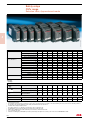
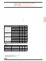
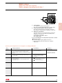
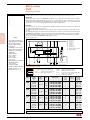
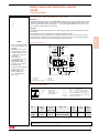
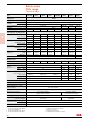
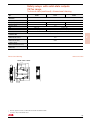
ABB Safety relays C57x and C67xx range Content Selection table................................................................................................................... 144 Approvals and marks........................................................................................................ 144 Safety for man and machine............................................................................................ 146 ABB General information...................................................................................................... Safety category acc. to EN 954-1................................................................................. Standards, functions, applications............................................................................... Cross circuit safety....................................................................................................... 146 147 148 149 Ordering details................................................................................................................... EMERGENCY STOP monitors and safety gate monitors C571, C571-AC................... EMERGENCY STOP monitors and safety gate monitor C573..................................... EMERGENCY STOP monitors and safety gate monitors C576, C577......................... EMERGENCY STOP monitors and safety gate monitors C572.................................... EMERGENCY STOP monitors and safety gate monitors C574 .................................. TWO-HAND control C575 . .......................................................................................... Extension unit C579 for contact expansion . ............................................................... Electronic safety relays with solid-state output C6700................................................. Electronic safety relays with solid-state output C6701................................................. Electronic safety relays with solid-state output C6702................................................. Technical data C57x . ........................................................................................................................... C67xx............................................................................................................................ Dimensional drawings C57x . ........................................................................................................................... C67xx............................................................................................................................ 150 150 151 152 153 154 155 156 157 158 159 160 162 161 163 143 2CDC110004C0205 3 Safety relays C57x range Selection table, Approvals and marks 2CDC 265 012 F0b04 3 Type Function Safety categorie acc. to EN 954-1 1) Connection Start EMERGENCY STOP Safety gate monitoring Press control Cross circuit detection B 1 2 3 4 single channel two channel Enabling circuits undelayed Enabling circuits delayed Signaling circuits automatic 8) monitored C571 C573 C571-AC C576 J 5) J J 5) J J 5) J J 5) J C577 J C572 J J C574 C575 C579 J 5) J 6) J J J J J J J J J J J J J J J J J J J J 1) J J J 1) J J J J J J J J J J J J J J J J J 6) J J J J J J J 3) J J J 7) J 3 n/o 2 n/c J J 2 n/o 2 n/o 1 n/c J, -, J 2 n/o 2 n/c - J 4) J 4) J 4) J 4) J 4) 4 n/o - J J J J J J J J J J 2 n/o J 3 n/o 1 n/c J 2 n/o J 2 n/o J - - - 2 n/o J J J J J J J J J J existing j pending Approvals A UL 508, CAN/CSA C22.2 No.14 J Baumusterbescheinigung E 6794 J Baumusterbescheinigung E 6795 M Marks a b 1) 2) 3) 4) 7) 8) 5) 6) BG Prüfzertifikat J J CE C-Tick J J J J J J j j J J J J J J J J J J J J J J J Possible with additional external measures. The figures apply only if the cables and sensors are laid safely and protected mechanically. See also user manual and application manual. The maximum safety category acc. EN 954-1, which can be reached, depends essentially on the external wiring, the choice of the sensors and the position of the machine. The nominal regulations for the safety at machines have to be observed. Possible with undelayed enable contact. The safety category acc. to EN 954-1 corresponds to those of the basic unit. The ON-button is not monitored. Valid only for C574 devices with auto-start. With monitored ON-button possible. Valid only for C574 devices with monitored start. Acc. to EN 574, type III C. Automatic restarting (as per EN 60204-1) must be prevented by the higher-level control system in the event of EMERGENCY STOP. 144 2CDC110004C0205 ABB Safety relays with solid-state outputs C67xx range Selection table, Approvals and marks 2CDC 265 031 F0b04 3 Type Function Safety categorie acc. to EN 954-1 Connection Start EMERGENCY-STOP Safety gate monitoring Press control Tread mats Electronic sensors Cascade input 24 V DC Cross short-circuit detection B 1 2 3 4 single channel two channel Enabling circuits Stop-Cat. 0 Enabling circuits Stop-Cat. 1 Signaling circuits automatic monitored C6700 J J C6701 J J C6702 J J J J J J J J J J J 1 J J J J J J J J 1 J J J J J J J J 2 1) J J 2 2) J J 1 1 3) J J J J 4) J existing j pending Approvals A UL 508, CAN/CSA C22.2 No.14 J J J TÜV TÜV J J J CE C-Tick J J J J J J Marks a b The outputs are only safe in connection with an external contactor. Can be used as electrical sensor input OFF-delay adjustable: 0.05-3 s or 0.5-30 s 4) One safety circuit can be used as signaling circuit. 1) 2) 3) ABB 145 2CDC110004C0205 Safety relays Safety for man and machine General information Safety for man and machine Machinery Directive 98/37/EEC The Machinery Directive 98/37/EEC is valid throughout Europe. This Directive obliges the machine manufacturer to guarantee, by attaching the CE mark, that all European Standards relevant to this machine type have been observed. The CE mark is attached by the manufacturer at his responsibility. No machine may be put into circulation or marketed without this CE mark. 3 Safety circuits must meet the following requirements depending on the safety categorie acc, to EN 954-1: J Coping with an individual fault including all sequential faults in the control circuit (single-fault tolerance). J Prevention of automatic restart of the machine when the EMERGENCY STOP facility is reset. J Setting up a redundant circuit by at least two contactor relays. J Creating diversity, e. g. by combining n/c and n/o contacts of the auxiliary contactors. J Cyclic monitoring of the safety circuit with each ON-OFF cycle. The ABB safety switching devices comply with all requirements of EN 60204, part 1, and are approved by the German Employers’ Liability Insurance Associations (BG) and/or TÜV (German Technical Inspection Authority). Standards for the safety of machinery EN 60204-1 "Functional safety of electrical/electronic/ programmable electronic safety-related systems" EN 418 "Safety of machinery; emergency stop equipment" EN 574 "Two-hand control devices" EN 954-1 "Safety-related parts of control systems" EN 1050 "Principles for risk assessment" EN 1088 "Interlocking devices associated with guards" IEC 61508 "Functional safety of electrical/programmable electronic safety related system" Important notice: The products described here in are designed to be components of a customized machinery safety-oriented control system. A complete safety-oriented system may include safety sensors, evaluators, actuators and signaling components. It is the responsibility of each company to conduct its own evaluation of the effectiveness of the safety system by trained individuals. ABB AG, its subsidiaries and affiliates (collectively "ABB") are not in a position to evaluate all of the characteristics of a given system or product or machine not designed by ABB. ABB accepts no liability for any recommendation that may be implied or stated here in. The warranty contained in the contract of sale by ABB is the sole warranty of ABB. Any statements contained here in do not create new warranties or modify existing ones. Fields of application: J EMERGENCY STOP circuits J Safety gate monitoring J Two-hand controls J Safety tread mats Practical experience has shown that, in a few applications, it is necessary to also monitor the sensing elements (EMERGENCY STOP buttons, limit switches of the safety gates etc.). A two-channel and/or cross circuit safe configuration is advisable in systems with a high level of contamination. In case of the twochannel control configuration, the contact part of the command unit has a redundant design. The supply leads can also be monitored for cross circuits. In case of a fault, the system reverts to safe state after the safety contacts (enabling circuits) are opened. Enabling circuits are safety contacts which reliably switch off the hazardous drives or machines. (n/o contacts which reliably open in case of faults). Depending on the device type, there are additional signalling contacts (n/c contacts which close in the event of a fault or semiconductor outputs). Of course, it is possible to also use enabling contacts as signaling contacts. Unique and clear terminal identification permits simple, reliable and rapid wiring. The risk of a wiring fault is appreciably reduced. 146 2CDC110004C0205 Further Information: User manual A user manual with a device description, connection diagrams and application information in several languages is enclosed with every safety switching device of C570 and C67xx range. Safety handbook You can find further information in the "Safety Engineering" application manual. It provides you with the required information on the relevant safety standards and project planning information. The entire range of components used for safety applications is explained in this Manual, from the sensor (emergency stop command devices and position switches), through evaluation units (safety switching devices C57x and fail-safe control AC 31 S) to the actuator (e. g. contactor for switching motors). All these components must be selected correctly in order to meet the requirements applicable to modern safety facilities. The Safety handbook can be downloaded on our homepage. ABB Safety relays Safety for man and machine Safety category according to EN 954-1 B 1 2 3 4 S1 S2 F2 P1 2CDC 262 001 F0004 F1 P2 P1 P2 3 S- Serious injuries S1 Slight (and normally reversible) injuries. S2 Serious (normally irreversible) injuries, including death. F- Frequency and/or duration of the risk exposure F1 Rare to frequent and/or short duration of exposure. F2 Frequent to sustained and/or longduration of exposure. P- Options for risk avoidance (generally referred to the speed and frequency at which the dangerous component moves and to the clearance from the dangerous component) P1 Possible under certain conditions. P2 Hardly possible. B, 1, 2, 3 and 4: Categories for safety-related components of controls Preferred category. Possible category requiring additional measures. Disproportionately extensive measures by comparison with the risk. Summary of the requirements for categories according to EN 954-1 Safety Summary of requirements System behavior2) category1) achieving safety B 1 The safety-related components of controls and/or their protection devices and their components must be designed, constructed, selected, assembled and combined in compliance with the applicable standards, such that they can withstand the anticipated influences. The requirements of B must be complied with. Time-proven components and time-proven safety principles have to be applied. The occurrence of a fault may lead to loss of the safety function. The occurrence of a fault may lead to loss of the safety function but the probability of occurrence is less than in category B. 2 The requirements of B and the use of the time-proven safety principles must be complied with. The safety function has to be checked at appropriate intervals by the machine control. ABB Principles for Predominantly characterized by selection of componentsl The occurrence of a fault may lead to loss of the safety function between the inspection intervals. The loss of the safety function is 147 2CDC110004C0205 oli.>>BD-6]TJ69Tj-45.35-1.2Td()Tj10.3920Td[()-905()]TJ34.9580Td[detMCC1122(The)]TJ/Span<</ActualText<FEFF0020>>BDC()920Td(by)Tj/Span<</ActualText<FEFF0020>>BDC()TjEMC(the)Tj/Span<</ActualText<FEFF0020>>BDC()TjEM/TjEMC(ijEMC(B.)TjETBT/T1_31Tf600603.5429249.3394Tm(2)Tj/T1_01Tf0.5560Td()Tj9.8360Td(The)Tj/Span<</ActualText<FEFF0020>>BDC()TjEMC[(r)18(equir)18(ements)]TJ/Span<</ActualText<FEFF0020>>BDC()TjEMC(of)Tj/Span<</ActualText<FEFF0020>>BDC()TjEMC(B)Tj/Span<</ActualText<FEFF0020>>BDC()TjEMC(and)Tj/Span<</ActualText<FEFF0020>>BDC()TjEMC(the)Tj/Span<</ActualText<FEFF0020>>BDC()TjEMC(use)Tj/Span<</ActualText<FEFF0020>>BDC()TjEMC(of)Tj/Span<</ActualText<FEFF0020>>BDC()TjEMC(the)Tj/Span<</ActualText<FEFF0020>>BDC()TjEMC[(time-pr)18(oven)]TJ/Span<</ActualText<FEFF0020>>BDC()TjEMC(safety)Tj/Span<</ActualText<FEFF0020>>BDC()TjEMC(principles)TjET03.5423227.4392.952.95ref*BT/T1_01Tf6006303.5429249.4394Tm[Ifr)18(oven)]TJ/Span<</ActualText<FEFF0020>>BDC()TjEMC(the)Tj/Span<</ActualText<FEFF0020>>BDC()TinglEMC(the)Tj/Span<</ActualText<FEFF0020>>BDC()TjEMC(fault)Tj/Span<</ActualText<FEFF0020>>BDC()jEMCs,EMC(of)Tj/Span<</ActualText<FEFF0020>>BDC()TjEMC(the)Tj/Span<</ActualText<FEFF0020>>BDC()TjEM Safety relays Safety for man and machine Standards, functions, applications Stop categories acc. to EN 60204 Safety functions Standard EN 60204 demands that every machine must feature the stop function of category 0. Stop functions of categories 1 and/or 2 must be provided if necessary for technical safety and/or functional requirements of the machine. Category 0 and category 1 stops must be operable independent of the operating mode, and a category 0 stop must have priority. Auto-start When the sensor circuit is closed the device is active. There are three categories of stop functions: Category 0: Shut-down by immediate switch-off of the energy supply to the machine drives. 3 Category 1: Controlled shut-down, where the energy supply to the machine drives is retained in order to achieve shut-down and where the energy supply is only interrupted after standstill has been reached. Category 2: A controlled shut-down where the energy supply to the machine drives is retained. If an ON-button is installed in the feedback circuit, a cross circuit of the feedback circuit is not monitored. Safety categories B, 1, 2, and 3 do not dictate a cross-circuit detection. If a device with the function "auto-start" shall be used for safety categories 4 and EMERGENCY STOP, the user has to guarantee a fault exclusion in the ON-button circuit, e. g. by a safe laying of the ONbutton line. Monitored start After a supply voltage failure or a saftey-related switch-off, the device will be started only by actuation of the ON-button. Especially for presses type III C to DIN 574 is possible. Safety category 4 to EN 954-1 is possible if the feed and the feedback circuit are monitored for cross circuits. After closing the sensor line the ON-button has to be actuated. Cross circuit safety Cross circuit safety denotes the ability of monitoring modules to detect faults (caused by pinched cable, earth-leakage, ect.) that can occur in the application being monitored and to prevent the release of the safety circuits until external faults have been removed. Scope of application Potential risks and hazards posed by a machine must be eliminated as fast as possible in the event of danger. For dangerous movements, the safe state is generally a standstill. All safety switching devices of C 570 range switch to de-energized state, i.e. standstill for drives, in the event of danger or fault. EMERGENCY STOP EMERGENCY STOP devices must have priority over all other functions. The energy supplied to the machine drives which may cause dangerous states must be switched off as fast as possible without further risks or dangers. Resetting the drives may not trigger a restart. The EMERGENCY STOP must act either as a stop of category 0 or as a stop of category 1. According EN 418 "EMERGENCY STOP equipment, functional aspects, principles for design" the resetting of the control device may only be possible as a result of an action by hand at the control device. Resetting the control device may not release a restart instruction. A restart of the machine may only be possible when all concerned operating elements have been reset individually and consciously by hand. The basic devices of the C57x range of safety switching devices can be used for EMERGENCY STOP applications up to category 4 acc. to EN 954-1. Depending on external wiring and cable routing of the sensors, category 3 or 4 acc. to EN 954-1 can be reached. Safety gate monitoring Device outputs Safety outputs The safety-related function must be controlled via safe output contacts, the so-called safety outputs. Safety outputs are always normally open contacts and switch off without delay. Signalling outputs For the signalling outputs, normally open contacts and normally closed contacts which may not perform safety-related functions are used. Safety outputs also be used as signalling outputs. Delayed safety outputs Drives which have a long overtravel must be decelerated in the event of danger. For this purpose, the energy supply must be maintained for electrical braking (stop category 1 acc. to EN 60 204-1). Contact expansion If the safety outputs of the basic device do not suffice, positively driven contactors (e. g. B6, B7) may be used for contact expansion. According to EN 1088, a distinction is made between interlocking guards and interlocking guards with guard locking. Here as well, the safety switching devices are used for EMERGENCY STOP applications. Controls up to category 4 to EN 954-1 are possible. Presses and punches Two-hand control is intended for devices on which the operator must use both hands simultaneously, thus protecting him against risks and dangers. 148 2CDC110004C0205 ABB Safety relays Safety for man and machine Cross circuit safety Cross circuit safety On ABB Safety relays C57x and C67xx, wich are designed to monitor EMERGENCY STOP, two-hand control units and safety gates, cross circuit safety is achieved by two channel (redundant) wiring of EMERGENCY STOP control devices (see diagram below). The two EMERGENCY STOP channels are operated at different voltages; thus the units will detect excessive current flow between the two points and disconnect the enabling circuits. L+/L1 1 4 3 2 7 3 5 6 A1 8 Y10 Y11 Y12 Y21 Y22 13 23 33 41 51 Y33 Y34 Y43 Y44 14 24 34 42 52 A2 PE PE L-/N 2CDC 262 024 F0004 ϑ Type of fault ➀ + ➄ Connection (cross circuit) between Y12 and Y21 The fault will be detected as a short-circuit (excessive current flow). The unit will disconnect the enabling circuits. ➁ Earthing of Y21 The fault will be detected as a short-circuit (excessive current flow). The unit will disconnect the enabling circuits. ➂ + ➃ Next operation of EMERGENCY STOP button will detect the fault as no voltage change will occur on Y12. The unit will prevent restarting unitl the fault has been removed and the EMERGENCY STOP module reset. ➅ - ➇ Immediate detection of the line interruption (voltage change on Y12) and opening of the enabling circuits The unit will prevent restarting unitl the fault has been removed and the EMERGENCY STOP module reset. The units incorporate internal electrical short-circuit protection which will trip when a fault occurs (short-circuit, cross circuit, ...) and disconnect the enabling circuits. After a fault has been removed, the safety relay will recognize this and again be ready for operation. Neither the unit nor any internal fusibles will need to be exchanged. ABB 149 2CDC110004C0205 Safety relays C571 and C571-AC Ordering details EMERGENCY STOP monitor and safety gate monitor C571 and C571-AC Application 2CDC 261 032 F0004 The safety relays C571 and C571-AC can be used in EMERGENCY STOP circuits according to EN 418 and in safety circuits according to VDE 0113 Part 1 (11.98) and/or EN 60 204-1 (11.98), e. g. with movable covers and guard doors. Depending on the external connections, safety categories B, 1, 2, 3 or 41) according to DIN EN 954-1 are achievable. When the safety combination is used in "automatic start" mode, automatic restarting (according to EN 60 204-1, sections 9.2.5.4.2 and 10.8.3) must be prevented by the higher-level control system in the event of EMERGENCY STOP. Functions C571 Block diagram C571 Block diagram C571-AC L+ L1 L-/L1 L+/L1 Y12 Y22 K1 K1 6 K2 5 K2 7 Y34 6 A1 A1 1 Y1 Y2 13 Y11 Y21 Y33 1 2 K1 4 14 24 K1 M 3~ K2 L-/N L- A2 13 23 A2 14 14 24 24 A2 2CDC 262 002 F0004 A1 14 24 M 3~ K2 L-/N ➀ Power pack ➁ Control logic ➂ Channel 1 ➃ Channel 2 ➄ External starting conditions ➅ Start pushbutton Connection diagram C571-AC A1-A2 Supply voltage 13-14, 23-24 Safety outputs Y1-Y2 K2 N Connection diagram C571 Y2 K1 4 K1 PTC-fuse Power pack ➂ Control logic Channel1 ➄ Channel 2 External starting conditions ➆ Start pushbutton 23 Y1 3 Y12 Y22 Y34 13 A1 23 Y11 A1 (n/o) Feedback loop, ON-button 13 23 A2 Y21 14 Y33 Y12 14 24 Y22 24 A2 Y34 2CDC 262 011 F0004 A2 C571-AC C571 K2 2CDC 262 013 F0004 5 13 A1 23 2 3 ➀ ➁ ➃ ➅ 13 23 ϑ J Auto-start J Supply voltage Vc at EMERGENCY STOP button or limit switch J Feedback loop for monitoring of external contactors J Safety outputs: 2 n/o contacts, positively guided J 3 LEDs for status indication J Safety category acc. to EN 954-1: B, 1, 2, 3, 41) 2CDC 262 014 F0004 3 The safety relays C571 and C571-AC have two enabling (safe) circuits which are configured as n/o contacts. The number of enabling circuits can be increased by adding one or more C579 extension units. Three LEDs (Power, Channel 1, Channel 2) indicate the operating state and function. When the EMERGENCY STOP button or the limit switch is unlocked and when the ON-button is pressed, the internal circuits of the safety relays and the external contactors are checked for proper functioning. A1-A2 13-14, 23-24 Y11-Y12 Y21-Y22 Y33-Y34 Supply voltage Safety outputs (n/o) Channel 1 Channel 2 Feedback loop, ON-button Type Supply voltage Uc Order code Pack. unit piece C571 C571 24 V DC 24 V AC/DC 1SAR 501 020 R0003 1SAR 501 020 R0001 1 1 0.26 / 0.57 0.26 / 0.57 115 V AC 230 V AC 1SAR 501 020 R0004 1SAR 501 020 R0005 1 1 0.29 / 0.64 0.29 / 0.64 C571-AC C571-AC Price 1 piece Weight 1 piece kg / lb Possible in combination with additional external measures. Information given in brackets only apply if cables and sensors are installed safely and mechanically protected. 1) • Approvals ................................................................................. 144 • Dimensional drawings .............................................................. 161 150 2CDC110004C0205 • Technical data ...........................................................................160 ABB Safety relays C573 Ordering details EMERGENCY STOP monitor and safety gate monitor C573 Application 1SAR 501 031 F0001 The safety relay C573 can be used in EMERGENCY STOP circuits according to EN 418 and in safety circuits according to VDE 0113 Part 1 (11.98) and/or EN 60 204-1 (11.98), e.g. with movable covers and guard doors. Depending on the external connections, safety categories B, 1, 2, 3 or 41) according to DIN EN 954-1 are achievable. Functions The safety relay C573 has three enabling circuits (safety outputs) which are configured as n/o contacts and a signal circuit configured as a n/c contact. The number of enabling circuits can be increased by adding one or more C579 extension units. Three LEDs (Power, Channel 1, Channel 2) indicate the operating state and function. When the EMERGENCY STOP button or the limit switch is unlocked and when the ON-button is pressed, the internal circuits of the safety relays and the external contactors are checked for proper functioning. Block diagram C573 J Auto-start J Supply voltage Vc at EMERGENCY STOP button or limit switch J Single- or two-channel connection J Feedback loop for monitoring of external contactors J Safety outputs: 3 n/o contacts, positively guided J Signalling contacts: 1 n/c contact, positively guided J 3 LEDs for status indication J Safety category acc. to EN 954-1: B, 1, 2, 3, 41) L+ L+/L1 K2 K1 7 6 A1 Y1 Y2 13 23 33 41 ϑ 1 2 4 K1 5 K2 C573 3 A2 14 K1 24 34 K2 M 3~ 42 H1 L-/N L- ➀ PTC-fuse ➁ Power pack ➂ Control logic ➃ Channel 1 ➄ Channel 2 ➅ External starting conditions 2CDC 262 015 F0004 C573 ➆ Start pushbutton 13 A1 23 Y1 33 Y2 A1 13 23 33 41 A2 14 24 34 42 41 14 42 24 A2 34 2CDC 262 004 F0004 Connection diagram C573 A1-A2 13-14, 23-24 41-42 Y1-Y2 Supply voltage Safety outputs (n/o) Signalling output (n/c) Feedback loop, ON-button Type Supply voltage Uc Order code C573 24 V DC/AC 1SAR 501 031 R0001 Pack. unit piece 1 Price 1 piece Weight 1 piece kg / lb 0.28 / 0.62 Possible in combination with additional external measures. Information given in brackets only apply if cables and sensors are installed safely and mechanically protected. 1) • Approvals ................................................................................. 144 • Dimensional drawings .............................................................. 161 ABB • Technical data ...........................................................................160 151 2CDC110004C0205 3 Safety relays C576 and C577 Ordering details EMERGENCY STOP monitor and safety gate monitor C576 and C577 Application 1SAR 501 120 F0001 The safety relays C576 and C577 can be used in safety circuits according to VDE 0113 Part 1 (11.98) or EN 60 204-1 (11.98), e. g. with movable covers and safety gates, the C577 in EMERGENCY STOP circuits according to EN 418. Depending on external connections, safety categories B, 1, 2, 3 or 4 according to DIN EN 954-1 are achievable. 3 Functions C576 The safety relays C576 and C577 have two enabling circuits (safety outputs) configured as n/o contacts. The number of enabling circuits can be increased by adding one or more C579 extension units. Three LEDs (Power, Channel 1, Channel 2) indicate operating state and function. When the EMERGENCY STOP button or the limit switch is unlocked and when the ON-button is pressed, the internal circuit of the safety relay and the external contactors are checked for proper functioning. On the C577, the ON circuit Y33-Y34 is checked for short circuit. This means that a fault is detected when Y33-Y34 is closed before the EMERGENCY STOP button is closed. 1SAR 501 220 F0001 Block diagram C576 and C577 L+/L1 Y12 Y22 K1 K2 7 A1 Y11 Y21 Y33 2 C577 Y12 Y22 Y34 K1 5 K2 14 K1 24 M 3~ K2 L-/N ➀ ➁ ➃ ➅ PTC-fuse Power pack ➂ Control logic Channel1 ➄ Channel 2 External starting conditions ➆ Start pushbutton 13 A1 23 Y11 A1 A2 Y21 14 Y33 Y12 13 23 14 24 Y22 24 A2 Y34 2CDC 262 007 F0004 Connection diagram C576 and C577 Y11-Y12 Y21-Y22 Y33-Y34 A1-A2 Supply voltage 13-14, 23-24 Safety outputs (n/o) Channel 1: EMERGENCY STOP or limit switch Channel 2: EMERGENCY STOP or limit switch Feedback loop, ON-button Type Supply voltage Uc Start Order code Pack unit piece C576 24 V AC/DC auto 1SAR 501 120 R0001 1 0.27 / 0.60 C577 24 V AC/DC monitored 1SAR 501 220 R0001 1 0.28 / 0.62 • Approvals ................................................................................. 144 • Dimensional drawings .............................................................. 161 2CDC110004C0205 4 2CDC 262 019 F0004 C576 / C577 A2 C577: J Monitored Start 152 23 3 C576: J Auto-Start C567 and C577: J Cross circuit detection at EMERGENCY STOP button or limit switch J 24 V DC at the EMERGENCY STOP button J Two-channel connection J Feedback loop for monitoring of external contactors J Safety outputs: 2 n/o contacts, positively guided J 3 LEDs for status indication J Safety category acc. to EN 954-1: B, 1, 2, 3, 4 Y34 13 ϑ 1 6 Price 1 piece Weight 1 piece kg / lb • Technical data ...........................................................................160 ABB 2CDC 262 003 F0004 C572 ABB 3 153 2CDC110004C0205 2CDC 261 050 F0b07 Safety relays C574 Ordering details EMERGENCY STOP monitor and safety gate monitor with time delay C574 Application 2CDC 261 051 F0b07 The safety relay C574 can be used in EMERGENCY STOP devices according to EN 418, in safety circuits according to VDE 0113 Part 1 (06.93) and/or EN 60 204-1 (12.97), such as for monitoring safety gates, or in circuits with controlled stand-still requirement (STOP Category 1). Depending on the external circuitry, this device can be used to realize safety categories B, 1, 2, 3 or 41) for undelayed enabling circuits according to DIN EN 954-1. Functions The C574 safety relay possesses two delayed and two undelaled enabling circuits (safety outputs) as n/o contacts and one undelayed signal output as n/c contact. Five LEDs (Power, Channel 1, Channel 2, delayed channel 1, delayed channel 2) indicate the operating status and the functions. The redundant safety relays, the electronics and the operated motor contactors are tested for proper functioning when the EMERGENCY STOP button or the limit switch button is unlatched, and when ON circuit Y33-Y34 is closed. On the C574 (monitored start), the ON circuit Y33-Y34 is checked for short circuit. This means that a fault ist detected when Y33-Y34 is closed before the EMERGENCY STOP button is closed. L+/L1 A1 Y10 Y11 Y12 Y21 Y22 23 31 47 57 4 2 1 13 ϑ 1 2 3 4 5 6 7 8 9 K1 Power pack PTC-fuse Control logic Channel 1 Channel 2 Channel 1 (+) Channel 2 (+) External starting conditions Start pushbutton 5 3 6 K2 7 PE A2 Y33 Y34 14 24 32 48 58 2CDC 262 017 F0004 J Auto-start or monitored start (depending on device) J Short circuit protection J Single- or two-channel connection J Feedback loop for monitoring of external contactors J Off-delay Tv continuously adjustable J Safety outputs: 2 n/o contacts (stop cat. 0), 2 n/o contacts (stop cat. 1), time delayed, pos. guided J Signalling output: 1 n/c contact, positively guided J 5 LEDs for status indication J Safety category acc. to EN 954-1: B, 1, 2, 3, 41) Block diagram C574 K1 M 3~ K2 9 8 H1 K1 K2 L-/N Connection diagram C574 13 A1 23 31 47 57 Y10 Y11 Y12 Y21 Y22 A1 13 23 31 A2 14 24 32 Y33 Y34 14 24 32 47 57 48 58 PE 48 A2 58 2CDC 262 005 F0004 C574 C574 3 A1-A2 13-14, 23-24 31-32 47-48, 57-58 Supply voltage Safety outputs undelayed (n/o) Signalling outputs undelayed (n/c) Safety outputs delayed (n/o) for monitored start: Y11-Y12, jumper = singel channel operation, Y21-Y22 EMERGENCY STOP at Y10-Y11 Y10-Y11 jumper = two channel operation, EMERGENCY STOP at Y11-Y12 and Y21-Y22 Y33-Y34 Feedback loop, ON-button Type Supply voltage Uc Off- delay Tv Start Order code Pack. unit piece C574 24 V DC 24 V AC 115 V AC 230 V AC 0,5-30 s monitored 1SAR 503 041 R0003 1SAR 503 041 R0002 1SAR 503 041 R0004 1SAR 503 041 R0005 1 1 1 1 0.50 / 1.10 0.50 / 1.10 0.65 / 1.43 0.65 / 1.43 0,5-30 s auto 1SAR 503 141 R0003 1SAR 503 141 R0002 1SAR 503 141 R0004 1SAR 503 141 R0005 1 1 1 1 0.50 / 1.10 0.50 / 1.10 0.65 / 1.43 0.65 / 1.43 0,05-3 s monitored 1SAR 533 241 R0003 1SAR 533 241 R0002 1SAR 533 241 R0004 1SAR 533 241 R0005 1 1 1 1 0.50 / 1.10 0.50 / 1.10 0.65 / 1.43 0.65 / 1.43 0,05-3 s auto 1SAR 533 141 R0003 1SAR 533 141 R0002 1SAR 533 141 R0004 1SAR 533 141 R0005 1 1 1 1 0.50 / 1.10 0.50 / 1.10 0.65 / 1.43 0.65 / 1.43 C574 24 V DC 24 V AC 115 V AC 230 V AC C574 24 V DC 24 V AC 115 V AC 230 V AC C574 24 V DC 24 V AC 115 V AC 230 V AC Price 1 piece Weight 1 piece kg / lb For undelayed enabling circuits only. 1) • Approvals .......................................144 154 2CDC110004C0205 • Technical data . ..............................160 • Dimensional drawings .......................161 ABB Safety relays C575 Ordering details Two-hand control C575 Application 2CDC 261 052 F0b07 C575 is suitable for installation in controls for presses: Hydraulic presses DIN EN 693, eccentric and related presses EN 692, screw presses EN 692. Functions The two-hand control unit C575 possesses two enabling circuits (safety outputs) configure as n/o contacts and two signal outputs configured as n/c contacts. Five LEDs (Power, S1 ON, S1 OFF, S2 ON, S2 OFF) indicate the operating status and the functions. The safety outputs are closed by simultaneous operation (< 0.5 s) of the pushbuttons S1 and S2. If one pushbutton is no longer pressed, the outputs open. They do not close again until both pushbuttons are no longer pressed and then simultaneously pressed again. 3 Block diagram C575 L+/L1 J Two-Hand control acc. to EN 574 Type III C J 24 V DC at the two-hand control switches J Simultaneity monitoring: 0.5 s J Cross circuit detection J Feedback loop for monitoring of external contactors J Safety outputs: 2 n/o contacts, positively guided J Signaling contacts: 2 n/c contacts, positively guided J 5 LEDs for status indication J Safety category acc. to EN type III C: B4 K1 K2 S1 7 A1 Y11 Y12 Y21 Y22 Y23 � � ϑ J 13 23 31 41 K1 � � � � C575 K2 Y31 Y32 Y33 A2 14 24 32 M 3~ 42 S2 K1 K2 H1 L-/N ➀ Power pack ➁ PTC-fuse ➅ Safety output ➂ Control logic ➃ Channel 1 ➆ External starting conditions 2CDC 262 018 F0004 C575 ➄ Channel 2 13 23 31 41 A1 Y11 Y12 Y21 Y22 Y23 A1 13 23 31 41 A2 14 24 32 42 Y31 Y32 Y33 14 24 32 42 A2 2CDC 262 006 F0004 Connection diagram C575 A1-A2 13-14, 23-24 31-32, 41-42 Supply voltage Safety outputs (n/o) Signalling outputs (n/c) Y11-Y12 Feedback loop Y21, Y22, Y23Pushbutton S1 Y31, Y32, Y33Pushbotton S2 Type Supply voltage Uc Order code Pack. unit piece C575 24 V DC 24 V AC 115 V AC 230 V AC 1SAR 504 022 R0003 1SAR 504 022 R0002 1SAR 504 022 R0004 1SAR 504 022 R0005 1 1 1 1 Price 1 piece Weight 1 piece kg / lb 0.42 / 0.93 0.42 / 0.93 0.52 / 1.15 0.52 / 1.15 According to EN 574, Type III C 1) • Approvals ................................................................................. 144 • Dimensional drawings .............................................................. 161 ABB • Technical data ...........................................................................160 155 2CDC110004C0205 Safety relays - Contact expansion C579 Ordering details Extension unit C579 for contact expansion Applications 1SAR 502 140 F0001 The C579 extension unit can be used in combination with all C57x basic units. It extends the number of enabling circuits. Depending on the external connection, safety categories B, 1, 2, 3 or 4 according to DIN EN 954-1 are achievable with this device. The C579 extension unit has four enabling circuits (safety circuits) configured as n/o circuits. Two LEDs (channel 1, channel 2) indicate operating state and function. The device is controlled via one enabling circuit of the safety relays C57x. When the EMERGENCY STOP pushbutton or the limit switch is unlocked and the ON-button is pressed, the internal circuit of the safety relay and the external contactors are checked for correct functioning. C579 Block diagram C579 L+/L1 J 1 safety output contact of the basic device is required for connection to the extension unit. J Safety outputs: 4 n/o contacts, positively guided J 2 LEDs for status indication J Safety category acc. to EN 954-1: B, 1, 2, 3, 4 depending on the external connection K3 K2 K4 K1 K5 7 K6 6 Y33 13 23 33 A1 13 23 33 43 51 14 24 34 44 52 ϑ 1 2 3 4 Y34 14 K1 24 34 A2 K3 K2 K4 K5 K6 L-/N ➀ ➁ ➃ ➅ 2CDC 262 020 F0004 C57x C579 5 PTC-fuse Power pack ➂ Control logic Channel1 ➄ Channel 2 External starting conditions ➆ Start pushbutton Connection diagram C579 13 A1 23 43 33 44 A1 13 23 33 43 51 A2 14 24 34 44 52 51 14 52 24 Type C579 C579-AC C579-AC A2 34 2CDC 262 009 F0004 3 Functions A1-A2 Supply voltage 13-14, 23-24, Safety outputs 33-34, 43-44 (n/o) 51-52 Signalling output (n/c) Supply voltage Uc Order code Pack. unit piece 24 V AC/DC 115 V AC 230 V AC 1SAR 502 040 R 0001 1SAR 502 040 R 0004 1SAR 502 040 R 0005 1 1 1 • Approvals ................................................................................. 144 • Dimensional drawings .............................................................. 161 156 2CDC110004C0205 Price 1 piece Weight 1 piece kg / lb 0.28 / 0.62 0.31 / 0.68 0.31 / 0.68 • Technical data ...........................................................................160 ABB 3 C6700 1 3 Y11 A1 Y12 Y34 Y33 A1 14 24 Y20 Y22 ABB Y21 14 A2 24 2CDC 262 010 F0004 2CDC 262 021 F0004 2 157 2CDC110004C0205 Safety relay with solid-state outputs C6701 Ordering details Electronic safety relay with solid-state output C6701 2CDC 261 027 F0004 Application The C6701 safety relay can be used in EMERGENCY STOP circuits according to EN 418 and in safety circuits according to EN 60 204-1 (11.98), e.g. in movable guards and safety gates. Depending on the external circuit elements, safety categories B, 1, 2, 3 or 4 according to DIN EN 954-1 or SIL 1, SIL 2 or SIL 3 according to IEC 61508 can be achieved. Functions The C6701 safety relay has two reliable solid-state outputs. Three LEDs (Power, Run, Fail) indicate the operating state and the function. When the device is put into operation it runs through a self-test to test the correct functioning of the internal electronics. All internal circuit components are monitored for faults cyclically during operation. External actuators or loads can be switched via safe outputs 14 and 24. C6701 Block diagram C6701 J Auto-start / monitored start J Cross circuit detection configurable J Feedback loop for monitoring of external contactors J 2 solid-state components à 1,5 A J Cascading input J 3 LEDs for status indication J Safety category acc. to EN 954-1: B, 1, 2, 3, 4 J Safety integrity level acc. to IEC 61508: SIL 1, SIL 2, SIL 3 L+ 6 Y12 Y22 K1 K2 5 A1 (+) Y34 Y11 Y21 Y35 Y32 6,3A 1 µC1 2 µC2 K1 3 4 C6701 K2 A2 (-) Y12 Y22 Y34 1 14 2CDC 262 022 F0004 3 24 M 3~ L+ 14 K1 K2 L- ➀ Power pack ➁ Control logic ➂ Channel 1 ➃ Channel 2 ➄ External starting conditions ➅ Start pushbutton Y11 A1 Y12 1 A1 Y34 Y32 14 24 Y35 Y22 Y21 14 A2 24 2CDC 262 029 F0004 Connection diagram C6701 A1-A2 14, 24 1 Y32 Y35 Y11-Y12 Y21-Y22 A1-Y34 Supply voltage Electronic outputs Cascading input Type Supply voltage Uc Release time after EMERG. STOP Order code Pack. unit piece C6701 24 V DC 30 ms min. 1SAR 511 320 R0003 1 • Approvals ................................................................................. 145 • Dimensional drawings .............................................................. 163 158 2CDC110004C0205 to supply = Auto-start open = monitored start to supply = without cross circuit detection open = with cross circuit detection Channel 1: EMERGENCY STOP or limit switch Channel 2: EMERGENCY STOP or limit switch Feedback loop, ON-button Price 1 piece Weight 1 piece kg / lb 0.17 / 0.37 • Technical data ...........................................................................162 ABB Safety relays with solid-state outputs C6702 Ordering details Electronic safety relays with solid-state output C6702 Application 2CDC 261 028 F0004 The C6702 safety relays can be used in EMERGENCY STOP circuits according to EN 418 and in safety circuits according to EN 60 204-1 (11.98), e.g. in movable guards and safety gates. Depending on the external circuit elements, safety categories B, 1, 2, 3 or 4 according to DIN EN 954-1 or SIL 1, SIL 2 or SIL 3 according to IEC 61508 can be achieved. Functions The C6702 solid-state safety relays have one safe solid-state output and one time-delayed safe solid- state output. Three LEDs (Power, Run, Fail) indicate the operating state and the function. When the device is put into operation it runs through a self-test to test the correct functioning of the internal electronics. All internal circuit components are monitored for faults cyclically during operation. External actuators or loads can be switched via safe outputs 14 and 28. Block diagram C6702 J Auto-start / monitored start J Cross circuit detection configurable J Feedback loop for monitoring of external contactors J 2 Safety outputs à 1,5 A: 1 solid-state component undelayed: stop category 0 1 solid-state component delayed (delay time adjustable from 0,05-3 s or 0,5-30 s): stop category 1 J Cascading input J 3 LEDs for status indication J Safety category acc. to EN 954-1: B, 1, 2, 3, 4 J Safety integrity level acc. to IEC 61508: SIL 1, SIL 2, SIL 3 L+ 6 Y12 Y22 K1 K2 5 A1 (+) Y34 Y11 Y21 Y35 Y32 6,3A K1 K2 1 µC1 2 µC2 3 C6702 4 A2 (-) Y12 Y22 Y34 1 14 M 3~ 28 2CDC 262 023 F0004 C6702 L+ 14 K1 K2 L- ➀ Power pack ➁ Control logic ➂ Channel 1 ➃ Channel 2 ➄ External starting conditions ➅ Start pushbutton Y11 A1 Y12 1 A1 Y34 Y32 �t 14 28 Y35 Y22 Y21 14 A2 28 2CDC 262 030 F0004 Connection diagram C6702 A1-A2 14 28 1 Y32 Y35 Y11-Y12 Y21-Y22 A1-Y34 Supply voltage Electronic output Delayed electronic output Cascading input Type Supply voltage Uc Release time after EMERG. STOP Order code Pack. unit piece C6702 C6702 24 V DC 24 V DC 0.05-3 s 0.5-30 s 1SAR 543 320 R0003 1SAR 513 320 R0003 1 1 • Approvals ................................................................................. 145 • Dimensional drawings .............................................................. 163 ABB to supply = Auto-start open = monitored start to supply = without cross circuit detection open = with cross circuit detection Channel 1: EMERGENCY STOP or limit switch Channel 2: EMERGENCY STOP or limit switch Feedback loop, ON-button Price 1 piece Weight 1 piece kg / lb 0.17 / 0.37 0.17 / 0.37 • Technical data ...........................................................................162 159 2CDC110004C0205 3 Safety relays C57x range Technical data Type C571(-AC) C573 C576 C577 Input circuit C579(-AC) C572 C574 C575 A1-A2 Supply voltage see ordering details AC Supply voltage tolerence -15 % ... +10 % DC -15 % ... +20 % Power consumption -15 % ... +10 % 1.5 W / VA Duty time 3 W / VA 4 W / VA 3 W / VA 100 ms 30 ms 40 ms 100 % Mains buffering 60 ms 60 ms 30 ms 80 ms 35 ms Time response - Control circuit 30 ms 1) Response time 3 monitored start - - auto-start 200 ms 2), 3) 200 ms 2) 100 ms - 30 ms - 25 ms 80 ms - - - - 150 ms 80 ms 20 ms Release time at EMERGENCY STOP 200 ms 200 ms 80 ms 20 ms - 25 ms 25 ms - at power failure 200 ms 200 ms 100 ms 150 ms 25 ms 4) 350 ms 100 ms - at EMERGENCY STOP 200 ms 200 ms 200 ms 400 ms - 200 ms after time lapse - at power failure 200 ms 200 ms 200 ms 600 ms 100 ms 500 ms 1s - EMERGENCY 200 ms 3) STOP 200 ms 25 ms 25 ms - 25 ms 25 ms - ON-button 150 ms 3) 150 ms 40 ms 25 ms - 25 ms 25 ms - Recovery time Minimum control pulse length / time 250 ms Simultaneity unlimited 500 ms Output circuits Kind of output 2 n/o 3 n/o + 1 n/c 2 n/o 2 n/o 4 n/o 3 n/o + 2 n/c 4 n/o 8) + 1 n/c 2 n/o + 2 n/c Contact material Rated switching current (IEC 60947-5-1) AC15 1150 V 5A 6A 5 A / 2 A 5) 6A AC15 230 V 5A 6A 5 A / 2 A 5) 6A DC13 24 V 5A 6A 5 A / 2 A 5) 6A 5A 6A 5A 6A 2 RC: 4 A 3 RC: 3.5 A 4 RC: 3 A 5A 4A 5A at Ta = 60 °C 2 RC: 4.5 A 3 RC: 4 A 4 RC: 3.5 A 6A 5A 6A at Ta = 50 °C 2 RC: 5 A 3 RC: 4.5 A 4 RC: 4 A 6A 5A 6A Rated thermal current for 2-4 release circuits at Ta = 70 °C Mechanical lifetime 1x10⁷ switching cycles Electrical lifetime 1x10⁵ switching cycles Operating frequency 1000/h at load with rated switching current Short-circuit proof IK = 1 kA 6), max. fuse rating 6 A slow, 10 A fast 7) General data 22.5 x 102 x 120 mm (0.89 x 4.02 x 4.72 inch) Dimensions (W x H x D) any Mounting position Degree of protection enclosure / terminals Ambient temperature range IP40 / IP20 operation storage at 115 V AC, 230 V AC: max. 200 ms at 24 V AC: max. 300 ms 3) at 115 V AC, 230 V AC: max. 300 ms 4) at 115 V AC, 230 V AC: max. 80 ms -40...+80 °C DIN rail (EN 50022) 7) 8) 1) 5) 2) 6) 2CDC110004C0205 IP20 / IP20 -25...+60 °C Mounting 160 45 x 102 x 120 mm (1.77 x 4.02 x 4.72 inch) undelayed / delayed release circuits other fuses on request signal circuit of C573 = 6 A 2 undelayed and 2 delayed n/o contacts ABB Safety relays C57x range Technical data (continued), dimensional drawings Type C571(-AC) C573 C576 C577 C579 C572 C574 C575 Electrical connection Wire size 2 x 2.5 mm2 / 1 x 4 mm2 (1 x 12 AWG / 2 x 14 AWG) rigid 2 x 1.5 mm2 / 1 x 2.5 mm2 (2 x 16 AWG / 2 x 14 AWG) fine-strand with wire end ferrules Standards Standards EN 60204-1 (VDE 0113-1), EN 292, EN 954-1 2002/95/EC RoHs Directive Safety catagory (EN 954-1) (EN 574) 41) 41) 4 4 - - - - Type-proof-test as basic device 4 42) 4 - - Type III C 10 a PFH 3 x 10⁻⁷ [1/h] 3) 3 x 10⁻⁸ [1/h] 3) Mechanical resistance (EN 60068) 3 x 10⁻⁹ [1/h] 3) 3 3 x 10⁻⁸ [1/h] 3) 8 g, 10 ms Isolation data Rated insulation voltage (VDE 0110, IEC 947-1) 300 V Rated impulse withstand voltage (VDE 0110, IEC 664) 4 kV Pollution degree (VDE 0110, IEC 664, IEC 255-5) 3 Overvoltage category (VDE 0110) III Dimensional drawings Dimensions in mm C572, C574, C575 1SVC 110 000 F 0314 1SVC 110 000 F 0313 C571, C573, C576, C577, C579 Possible with additional external measures. The figures apply only if the cables and sensors are laid safely and protected mechanically. See also user manual and application manual. Possible with undelayed enable contact. 3) according to target of IEC 61508-1 Tab 3 1) 2) ABB 161 2CDC110004C0205 Safety relays with solid-state outputs C67xx range Technical data (continued), dimensional drawing Type C6700 C6701 C6702 Standards Standards EN 60204-1 (VDE 0113-1), EN 292, EN 954-1, IEC 61508, DIN EN 0116 1) Safety category (EN 954-1) 3 4 4 Safety integrity level (IEC 61508) 2 3 3 Type-proof-test 10 a PFD 9,18 x 10⁻⁴ PFH 3 x 10 [1/h] -7 2,347 x 10-6 5,358 x 10-11 [1/h] 2) 2) Mechanical resistance (EN 60068) 8 g / 10 ms, 15 g / 5 ms Insulation data Rated insulation voltage (VDE 0110, IEC 947-1) 50 V Rated impulse withstand voltage (VDE 0110, IEC 664) 500 V 3 Pollution degree (VDE 0110, IEC 664, IEC 255-5) Overvoltage category (VDE 0110) Dimensional drawing Dimensions in mm C6700 / C6701 / C6702 86 63,5 35 22,5 Y11 Y12 Y34 A1 Y33 5 Y20 Y21 A2 Y22 14 15 1) 2) 26,5 24 1SVC 110 000 F 0310 80 100 110 82 62 73,5 POWER RUN FAIL Electrical equipment of furnaces. VDE-Certificat for C6701 and C6702 available. according to target of IEC 61508-1 Tab 3 ABB 163 2CDC110004C0205 Notes 3 164 2CDC110004C0205 ABB


![() [IT] LK/S 4.2](http://vs1.manualzilla.com/store/data/006135181_1-b116a464f76fc09be64d6bd073b26233-150x150.png)