1
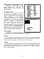
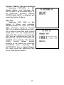
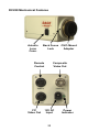
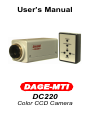
User’s Manual
DAGE-MTI
DC220
Color CCD Camera
Table of Contents
PAGE
3
4
5
5
5
5
6
7
7
7
8
9
10
11
12
13
13
14
14
14
14
14
15
15
16
16
17
17
18
19
19
20
21
22
23
Purchaser’s Record
Introduction
Installation
Power In
Video Out
Y/C Out
Quick Setup
Operation
Main Menu Camera Settings
Camera Title
Sense Up
ALC/ELC (Shutter)
BLC (Back Light Compensation)
AGC (Automatic Gain Control)
W/B (White Balance)
Zoom
Exit
Option Menu Camera Settings
Mask A, B, C, D
Posi/Nega
H-REV (Horizontal Reverse)
V-Rev (Vertical Reverse)
Freeze
Priority
Gamma
Return/Next
Option 2 Menu Camera Settings
APC Set (Aperture Control)
Connector Pin-outs
Back-Focus Adjustment
CS/C Mount Adaptor
Troubleshooting
Specifications
DC220 Mechanical Features
Warranty
2
Purchaser’s Record
Model Name:
□DC220
Serial Number:
Dealer’s Name:
Dealer’s Address:
Dealer’s Phone Number:
Date Purchased:
P.O. Number:
3
Introduction
The DAGE-MTI DC-220 is a compact color camera based
upon a 1/2” Interline CCD that provides a high resolution color
image. The CCD employs a state of the art microlens design to
increase the light gathering capability of the CCD. Digital Signal
Processing (DSP) goes beyond the traditional limitations of analog
cameras by providing ultimate video enhancement and function
and when combined with the built in video memory allows a host
of features such as automatic extended exposure integration
(sense-up), freeze video display with the push of button, horizontal
and vertical image reverse, and zooming. A convenient keypad
remote is included to utilize the On Screen Display (OSD)
commands to setup all the camera features and options. High
quality Y/C video and composite video outputs are provided.
Full automatic and manual modes allow for exceptional image
results even under difficult lighting conditions. Memory back-up of
all camera settings allows you to “set and forget” so you can
spend your time productively obtaining the images needed to
perform your job.
The camera mounts to the industry standard C-Mount optics
and also CS-Mount lensing if necessary. This allows connection to
Microscopes with C-Mount ports as well as both C and CS-Mount
lenses. Optionally DAGE-MTI carries Optical Couplers to mate
with microscopes. These couplers convert the 1/2” camera sensor
optics to the microscope so the camera views a similar size as
what is viewed in the ocular ports. These couplers also have the
advantage of increasing the sensitivity by means of taking the
normal 1 inch view being sent to the camera and concentrating
this light into a 1/2” view at the camera.
The DAGE-MTI DC220 camera provides an affordable high
performance camera with exceptional quality and features to
obtain exceptional images in almost any imaging situation.
4
Installation
Power In
The green PL indicator lights when power is supplied to the
camera. The camera requires approximately 250mA at 12VDC.
The included power supply provides a regulated power source to
the camera.
Caution: Do not use an unregulated power supply. Use only
factory approved supplies. Optional supplies are available for
applications requiring nonstandard USA mains.
Video Out
The Video Out BNC connector provides an NTSC composite
video signal to be terminated into 75 Ω. For improved video
performance, the Y/C video output signal should be used when
possible.
Y/C Out
The Y/C or sometimes referred to as “S Video” connector
provides Y (luminance) and C (color) signals to be terminated into
75Ω. Because the signals are separate and not combined like the
composite output, a higher quality image can be obtained.
Remote
All camera functions are accessible through the On Screen
Display (OSD) menu. Since the camera may be installed in
difficult to reach areas, the included remote control connects to
the camera allowing easy access to the OSD. All settings are
stored in memory; therefore it is only necessary to attach the
remote when setting changes are desired.
5
Quick Setup
The DC220 is shipped with the camera in the following modes
in order to produce the best image under varying imaging
conditions:
• W/B-ATW (Auto White Balance in Auto Trace)
• AGC-On (Automatic Gain on)
• ELC (Automatic Shutter on)
• Gamma-0.45 (Gamma on)
Depending on your application, you may want to initially
change these settings for optimal performance.
•
To White Balance to a white reference (AWB):
1. Press and hold the MENU key for 2 seconds to activate
the OSD menu.
2. Use UP/DOWN keys to select W/B.
3. Press RIGHT key to switch the mode to AWB.
4. Image a white reference object and then press
MENU/ENTER key to perform AWB routine.
•
To set Gain to Minimum (AGC Off):
1. Press and hold the MENU key for 2 seconds to activate
the OSD menu.
2. Use UP/DOWN keys to select AGC.
3. Press RIGHT key to switch the mode to AGC-OFF.
•
To set Automatic Shutter (ELC) off:
1. Press and hold the MENU key for 2 seconds to activate
the OSD menu.
2. Use UP/DOWN keys to select ELC.
3. Press RIGHT key to switch the mode to ALC.
•
To set Gamma off: A higher contrast image can be
obtained by setting gamma off (linear).
1. Press and hold the MENU key for 2 seconds to activate
the OSD menu.
2. Use UP/DOWN keys to select OPTION.
3. Press MENU/ENTER key to enter the OPTION menu.
4. Use UP/DOWN keys to select GAMMA.
5. Press RIGHT key to switch mode to GAMMA 1.00.
6
Operation
Main Menu Camera Settings
Connect the DC-220 to the
Remote Control and Monitor, and
then apply power. Push and hold
(for 2 seconds) the MENU key on
the remote to activate the On
Screen Display (OSD) menu. Use
the UP, DOWN keys to select
desired functions (flashing), then
press the LEFT, RIGHT keys to
activate or select features. A period
(.) will appear next to selections
which have an additional menu
available. Press the MENU/ENTER key to enter additional menus.
Select RETURN and press MENU/ENTER to return to previous
menus.
Camera Title
The Camera Title provides 12
characters letters, numbers or
symbols. To edit the title, select
TITLE (flashing) with the UP or
DOWN keys. Press RIGHT to turn
on the title menu, then press
MENU/ENTER to enter the title
menu. Use the UP, DOWN, LEFT
and RIGHT buttons to navigate and
select
characters
with
the
MENU/ENTER key. The location of
the title display can be set by
entering the LOCATION submenu. To return back to previous
menus, select RETURN and press MENU/ENTER.
7
Sense Up
The Sense Up controls extended exposure (sensor
integration). Values from 2x to 128x may be selected with the
LEFT/RIGHT keys. This feature increases the exposure time in
order to achieve higher sensitivity in low light environments.
Sense up operates in an automatic mode where the exposure
time is increased as needed (dependent on scene conditions) to
produce full video output. The value selected is the maximum
allowed, therefore only 4x may be used even if sense up is set
from 6x to 128x. When Automatic Gain Control (AGC) is also
activated there is another control located in the Option Menu
called Priority which sets whether the AGC or Sense Up has
priority (initially active before the other).
NOTES:
Sense Up may produce long exposure times where the
frame rate will slow down. Also any movement in the scene
may be blurred during long exposures. In this case AGC
should have priority over Sense-up to keep exposure time to a
minimum.
Long exposure times and/or high gain levels may create
“hot pixels”. This is a natural dark current phenomenon
associated with the temperature and exposure time/gain level
of CCD imagers and is not a defect. Try increasing light level
or limiting AGC to overcome the effect of dark current.
8
ALC/ELC
Pressing the LEFT/RIGHT keys while ALC/ELC is selected will
toggle between the two modes. Pressing MENU/ENTER will bring
up the respective ALC or ELC submenu.
ALC- The Automatic Lens
Control (ALC) submenu has a
manual
SHUTTER
setting
allowing selection of shutter
times from 1/60th second (OFF)
to 1/12,000th second. The
LEVEL control is used with an
autoiris lens (DC Type) to
control the desired level to
which the autoiris lens will track.
ELC- Setting the camera to
Electronic Lens Control (ELC)
turns on the automatic shutter
control. In ELC the shutter time
is
automatically
adjusted
between 1/60th to 1/120,000th
second allowing use in areas of
very high brightness. The ELC
submenu has a LEVEL control
which sets the desired level to
which the automatic shutter will
track.
9
BLC
The Back Light Compensation (BLC) control can compensate
for scenes in which the viewing object has light behind the subject
(back light). Pressing the LEFT/RIGHT keys while BLC is selected
will toggle through BLC OFF (no compensation), BLC ON
(compensation applied) and BLC PEAK. Pressing MENU/ENTER
will bring up the respective BLC ON or BLC PEAK submenu.
BLC ON- This submenu has an
AREA SET submenu which
allows selection of 8x6 (48 zone)
area
selection.
Use
the
UP/DOWN/ LEFT/RIGHT and
MENU/ENTER keys to navigate
and select areas in which the
BLC compensation will be
applied. Press the MENU/
ENTER key for 2 seconds to
leave the Area Set submenu.
The PRESET ON/OFF selection
allows your custom area to be
applied (OFF) or a preset center
12 zone selection (ON) to be
applied.
PEAK- This submenu adjustment sets the BLC control to
operate using peak or average
detection as selected by the
LEVEL control.
NOTE: The Back Light function
works only when AGC and/or
Auto Shutter are on and the
illumination level is sufficient for
the
automatic
circuits
to
function.
10
AGC
The Automatic Gain Control (AGC) automatically sets the
camera video gain within a 0 to 18 dB range to provide the correct
video output signal. Pressing the LEFT/RIGHT keys while AGC is
selected will toggle through AGC OFF(no compensation), AGC
ON (compensation applied) and AGC MANU (manual gain).
Pressing MENU/ENTER will bring up the respective AGC ON or
AGC MANU submenu.
AGC OFF- The camera is in a
non adjustable manual gain
fixed mode in which the gain is
set to minimum. This setting
allows the best possible signal
to noise ratio.
AGC
ONThe
camera
automatically sets the gain
dependent on the video scene.
The AGC ON submenu has a
LEVEL control which sets the
maximum allowable gain to be
used in automatic mode.
AGC MANU- The camera is in
an adjustable manual gain fixed
mode.
The
AGC
MANU
submenu has a LEVEL control
which sets the manual gain
level.
11
W/B
The White Balance (W/B) controls the balance of colors to
produce white. Pressing the LEFT/RIGHT keys while W/B is
selected will toggle through W/B ATW (Auto Trace White
Balance), W/B AWC (Automatic White Balance) and W/B MANU
(Manual White Balance). Pressing MENU/ENTER will bring up the
submenu in W/B MANU.
W/B ATW- Measures the object color temperature and adjusts
the white balance automatically while tracing variations in color
temperature and readjusting the white balance as needed.
W/B AWB- Measures the object color temperature and adjusts
the white balance automatically when the MENU/ENTER
button is pressed. The balance is then stored in memory and
retained until another balance routine is performed. A white
reference subject can also be used to white balance to. If the
illumination source is changed or the intensity is changed, then
another AWB routine should be performed.
W/B MANU- The W/B MANU
submenu contains 2 fixed color
temperature settings (3200° for
indoor incandescent lighting or
5600° for outdoor lighting), or
OFF(USER) setting with manual
RED and BLUE adjustments
(Green is fixed).
12
Sync
This optional feature is not installed in this camera model.
Option
Pressing MENU/ENTER while Option is selected will open the
Option menu. Refer to the Option menu settings in the next
chapter for operation of Option features.
Zoom
A digital zoom feature is
available which allows up to a 2x
zoom. Pressing the LEFT/RIGHT
keys while Zoom is selected will
toggle the zoom feature ON/OFF.
Pressing the MENU/ENTER key
while the Zoom On is selected will
bring up the Zoom submenu where
a variable level of Zoom can be
selected. Note the zoom will cause
a decrease in resolution as only a
portion of the image data is
displayed.
Motion Det
This optional feature is not installed in this camera model.
Exit
The Exit menu allows the user to save all changes made or
reset to the factory default settings (preset). Pressing the
LEFT/RIGHT keys while Exit is selected will toggle between SAVE
and PRESET. Pressing MENU/ENTER while set to SAVE will
save all modified menu items and Exit the OSD menu. Pressing
MENU/ENTER while set to PRESET will load factory preset
values into the menu items and exit the OSD menu.
13
Option Menu Camera Settings
Selecting OPTION-SET in the
Main menu and pressing the
MENU/ENTER key will enter the
Option Menu.
Mask A, B, C, D
There are 4 masks (A, B, C, D)
which can be applied in order to
cover or mask areas of the scene in
which display is not desired.
Pressing LEFT/RIGHT while MASK
is selected will turn the feature
ON/OFF, pressing MENU/ENTER
while the mask is on will bring up
the mask submenu where the
Location and Size can be adjusted
with additional corresponding submenus. Use the UP/DOWN/LEFT/
RIGHT keys to adjust the location or
size of each mask as necessary.
POSI/ NEGA
A positive or negative image can be obtained by pressing the
LEFT/RIGHT key while POSI/NEGA is selected.
H-REV
The image can be reversed horizontally by selecting H-REV
then pressing the LEFT/RIGHT key to turn the feature ON/OFF.
Can be used to create or correct for a “mirror image”.
V-REV
The image can be reversed vertically by selecting V-REV then
pressing the LEFT/RIGHT key to turn the feature ON/OFF. H-REV
and V-REV combined will create or correct for an upside down or
180° rotated image.
14
Freeze
The FREEZE key on the remote allows an image to be stored
in camera memory. By selecting FREEZE in the option menu and
pressing the LEFT/RIGHT key will allow the selection of
FRAME/FIELD mode to be used.
Frame- Frame mode uses both the even and odd interlaced
vertical fields when capturing and results in the highest vertical
resolution. In situations where movement is involved,
“zippering” between fields may result due to the 1/60th second
delay between fields.
Field- Field mode uses only one field when capturing and is
more suitable in situations where movement is involved.
Capturing only one field eliminates the “zippering” between
fields during movement in Frame mode at the expense of
reduced vertical resolution by using only one field.
Priority
By selecting Priority in the option menu and pressing the
LEFT/RIGHT key will allow the selection of AGC/SENSE mode to
be used. The Priority controls which feature (AGC or Sense-up)
has 1st priority when both controls are activated.
Priority AGC- Allows AGC to operate first when AGC and
Sense-up are both activated. When the output signal is low the
camera will compensate using Gain first via AGC (up to the
maximum selected by the AGC-ON menu Level control) before
using integration via the Sense-up control.
Priority Sense- Allows Sense-up to operate first when AGC
and Sense-up are both activated. When the output signal is
low the camera will compensate using integration first via
Sense-up (up to the maximum X value selected) before using
Gain via the AGC control.
15
Gamma
By selecting GAMMA in the option menu and pressing the
LEFT/RIGHT key will allow the selection of 0.45/1.00 mode to be
used. Gamma 0.45 provides compensation for display on a CRT
display monitor. Gamma 1.00 provides a linear output with no
gamma correction.
Return/Next
Selecting RETURN in the Option Menu and pressing the
LEFT/RIGHT key will allow NEXT to be displayed. Pressing
MENU/ENTER while NEXT is selected will enter the Option 2
Menu whereas pressing MENU/ENTER with RETURN selected
will return back to the Main Menu.
16
Option 2 Menu Camera Settings
Selecting RETURN in the
Option Menu and pressing the
LEFT/RIGHT key will allow NEXT to
be displayed. Pressing MENU/
ENTER while NEXT is selected will
enter the Option 2 Menu.
APC Set
Selecting APC SET in the
Option 2 Menu and pressing
MENU/ENTER will enter the APC
SET submenu. Aperture Control
(APC) is a detail enhancement feature in which horizontal and vertical
detail gain can be independently
adjusted. The amount of horizontal
and vertical enhancement can be
adjusted by using the H-GAIN and
V-GAIN level controls. The Preset
Off/On control allows default
settings to be loaded by selecting
Preset-Off then pressing the
LEFT/RIGHT key to select PresetOn, then press the MENU/ENTER
key to load preset values.
17
Connector Pin-outs
Remote (OSD Keyboard)
This 8 pin mini-din connector is used
for the OSD Remote to set-up or
change camera function settings. The
pin-out is as follows:
1. RIGHT
5. MENU
2. LEFT
6. FREEZE
3. UP
7. GROUND
4. DOWN
8. N/C
Y/C Out (Video)
This 4 pin mini-din connector provides
Y (luminance) and C (color) output
signals to be terminated into 75Ω.
The pin-out is as follows:
1. GROUND
2. GROUND
3. Y (LUMINANCE)
4. C (COLOR)
Auto Iris (Lens)
1
3
2
4
This 4 pin connector provides lens
control signals to operate a DC type
Auto Iris lens.
The pin-out is as follows:
1. DUMP (-)
2. DUMP (+)
3. DRIVE
4. GROUND
Video Out (Composite)
A standard BNC connector supplying composite video output
into a 75 ohm terminated load.
Power In
A standard 2.1mm DC input jack, 12V DC center positive. Use
only approved regulated power supplies.
18
Back-Focus Adjustment
The DC220 camera is designed with a lens mount insert to
allow adjustment of the lens position relative to the camera
sensor. This is typically referred to as a “Back-Focus” adjustment.
The Back-Focus is calibrated at the factory and should not need
readjustment, however if adjustment is necessary follow the
procedure below:
1. Loosen the set screws on the side and bottom of front
casting with a 1.5mm hex wrench (included).
2. Set the lens to maximum aperture and to ∞ focus position.
3. View an object which is 20M or more away, then rotate the
brass lens mount ring until the image is in focus.
4. Tighten the set screws.
CS/C-Mount Adaptor
DC220 cameras are designed with a “CS” type lens mount and
are shipped with a “CS” to “C” mount adapter. (5mm spacer) A
lens designed with a CS type mount requires a “Back-Focus”
distance of “12.5mm” from the lens to the camera sensor. A lens
designed with a C type mount requires a “17.5mm Back-Focus”.
Thus a C-Mount lens can be used on a camera designed for a
CS-Mount lens by adding a 5mm CS-to-C Mount spacer between
the lens and camera body. The DC220 camera is supplied with a
5mm C-mount spacer attached. To use CS type lenses, remove
the 5mm spacer.
19
Troubleshooting
No Picture (Check or try the following):
1. Camera Power On?
a. External Power Supply Attached?
b. AC Power On?
c. Power Indicator On?
2. Monitor Connected to Camera Video Output?
a. Monitor Power On?
3. Light Level Too Low?
a. Open Camera Lens.
b. Set Camera Shutter to ELC or ALC (Off).
c. Set Camera AGC to On (Max).
Picture Saturated (Check or try the following):
1. Video Output Cable Terminated Into 75Ω?
2. Light Level Too High?
a. Reduce Lens Setting.
b. Set Shutter to ELC (Auto).
c. Reduce Auto Shutter ELC Level.
d. Set Gain to AGC On or Off (not Manu)
e. Set Back-Light Compensation to Off.
Menu Doesn’t Appear (Check or try the following):
1. Remote Plugged in Securely?
2. Pressing MENU/ENTER Key for 2 Seconds?
20
Specifications:
CCD Sensor:
1/2” Interline w/ Micro Lenses
768x494 Effective Pixels (NTSC)
Sensitivity @30fps:
0.4 Lux (F1.2, 5600°K, 30 IRE)
Sensitivity @128x:
0.004 Lux (F1.2, 5600°K, 10 IRE)
Resolution:
480 TVL (H), 375 TVL (V)
Signal to Noise:
52dB (Min)/ 60dB (Typ), (AGC off)
AGC Range:
0-18dB
Digital Processing:
10 Bits
Edge Enhancement:
2H Horizontal & Vertical
Memory Back-up:
EEPROM (non volatile)
White Balance Modes:
ATW, AWC & Manual
White Balance Range:
3200°K to 10,000°K
Video Output:
1Vpp, 75Ω comp & Y/C
Gamma Correction:
.45 and 1.0 (Linear)
Electronic Shutter:
Auto from 1/60 to 1/120,000 sec
Manual Shutter:
16 values from 1/60 -1/12,000 sec
Auto Iris:
DC type lens control
Lens Mount:
“C” or “CS” adjustable back-focus
Camera Mount:
¼”-20, Top and Bottom Mount
Dimensions (Camera):
2” W x 2” H x 4.5” L
Dimensions (Remote):
2.3” W x 1.1” H x 3.6” L (5.5’ cord)
Weight:
11 Ounces (312 g)
Power:
3 W (12VDC, 250mA)
Operating Temperature: 0°C to +50°C
Safety Approval:
CE
Other Features:
OSD (On Screen Display)
On Screen Title
Auto Integration up to 128X (Sense-up)
BLC (Back Light Compensation)
Zoom Feature
H & V Scan Reverse
Freeze (Frame/Field Memory)
Mask Function
Pos/Neg Image Selection
Remote Control & Power supply included
21
DC220 Mechanical Features
AutoIris
Lens
Conn.
Back Focus CS/C-Mount
Adaptor
Lock
Remote
Control
Y/C
Video Out
Composite
Video Out
12V DC
Input
22
Power
Indicator
Warranty
The DAGE-MTI DC220 is warranted to be free of defects in
material and workmanship in normal use for a period of one year
from the original date of purchase from DAGE-MTI.
This warranty does not apply to units which have been subject
to abuse, neglect, accident, improper installation, or on which the
serial number has been removed or damaged. Units that have
been altered without the prior permission of DAGE-MTI are not
covered by this warranty.
This warranty does not apply to other equipment furnished by
DAGE-MTI, which is listed or otherwise identified as manufactured
by another and therefore shall be covered by the other
manufactures’ applicable warranty.
This warranty is valid only if the malfunctioning unit is returned
to DAGE-MTI service depot; this warranty does not cover onlocation service. If warranty work is needed, the following should
be contacted:
DAGE-MTI of MC, INC.
Customer Service
701 N. Roeske Ave.
Michigan City, IN 46360
(219) 872-5514
[email protected]
This warranty does not cover:
• Problems caused by or inflicted upon associated
equipment such as computers, digitizing systems, video
tape recorders, cameras, microscopes, etc.
• Damage caused by accident, misuse, improper power
source, fire, flood, lightning, other acts of God, war, and
repair or alteration by other than a DAGE-MTI authorized
service organization.
• Labor or incurred charges required in removing or
installing the product, down time, failure of the product to
perform properly, and any consequential damages.
• Transit damage.
Unit must be properly packaged (in original packing, if
possible) when being returned under warranty.
23
DAGE-MTI
DAGE-MTI of MC, Inc.
701 N. Roeske Ave.
Michigan City, IN 46360
(219) 872-5514
Fax: (219) 872-5559
www.dagemti.com
970204-02
01/13/05
24