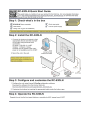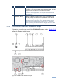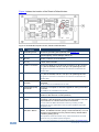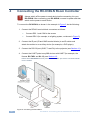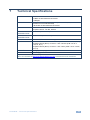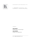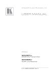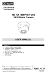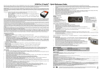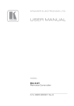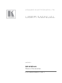
1
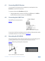
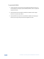
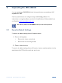
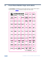
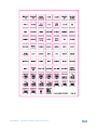
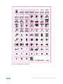
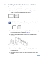
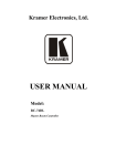
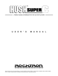
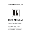
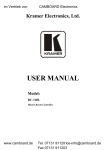
K R A ME R E LE CT R O N IC S L TD . USER MANUAL MODEL: RC-63DLN Room Controller P/N: 2900-300317 Rev 1 Contents 1 Introduction 1 2 2.1 2.2 2.3 3 3.1 3.2 Getting Started Achieving the Best Performance Safety Instructions Recycling Kramer Products Overview The RC-63DLN Room Controller Front Panel The RC-63DLN Room Controller Rear Panel 2 2 2 3 4 5 6 4 4.1 4.2 4.3 Connecting the RC-63DLN Room Controller Connecting RS-232 Devices Connecting the K-NET Port Grounding the RC-63DLN 10 11 11 11 5 5.1 6 6.1 Operating the RC-63DLN Reset to Default Settings Front Panel Button Caps and Labels Installing the Front Panel Button Caps and Labels 13 13 14 17 7 Technical Specifications 19 Figures Figure 1: RC-63DLN Front Panel Figure 2: RC-63DLN Rear Panel for the USA Figure 3: RC-63DLN Rear Panel for Europe Figure 4: RC-63DLN European Version, Reset to Default Button Figure 5: Connecting the RC-63DLN Figure 6: K-NET PINOUT Connection Figure 7: Grounding Connection Components Figure 8: Sample Button Label Sheet Figure 9: Button Cap Orientation without/with Label for USA version Figure 10: Placing the Button Cap (Left – EU version, Right – US version) 5 6 7 8 10 11 11 16 17 17 RC-63DLN – Contents i 1 Introduction Welcome to Kramer Electronics! Since 1981, Kramer Electronics has been providing a world of unique, creative, and affordable solutions to the vast range of problems that confront video, audio, presentation, and broadcasting professionals on a daily basis. In recent years, we have redesigned and upgraded most of our line, making the best even better! Our 1,000-plus different models now appear in 11 groups that are clearly defined by function: GROUP 1: Distribution Amplifiers; GROUP 2: Switchers and Routers; GROUP 3: Control Systems; GROUP 4: Format/Standards Converters; GROUP 5: Range Extenders and Repeaters; GROUP 6: Specialty AV Products; GROUP 7: Scan Converters and Scalers; GROUP 8: Cables and Connectors; GROUP 9: Room Connectivity; GROUP 10: Accessories and Rack Adapters and GROUP 11: Sierra Video Products. Congratulations on purchasing your Kramer RC-63DLN Room Controller which is designed to let you remotely control an A/V system with ease, in a multimedia classroom or conference room. RC-63DLN – Introduction 1 2 Getting Started We recommend that you: Unpack the equipment carefully and save the original box and packaging materials for possible future shipment Review the contents of this user manual i 2.1 Go to http://www.kramerelectronics.com/support/product_downloads.asp to check for up-to-date user manuals, application programs, and to check if firmware upgrades are available (where appropriate). Achieving the Best Performance To achieve the best performance: Use only good quality connection cables (we recommend Kramer highperformance, high-resolution cables) to avoid interference, deterioration in signal quality due to poor matching, and elevated noise levels (often associated with low quality cables) Do not secure the cables in tight bundles or roll the slack into tight coils Avoid interference from neighboring electrical appliances that may adversely influence signal quality Position your Kramer RC-63DLN away from moisture, excessive sunlight and dust ! 2.2 Safety Instructions ! 2 This equipment is to be used only inside a building. It may only be connected to other equipment that is installed inside a building. Caution: There are no operator serviceable parts inside the unit Warning: Use only the Kramer Electronics input power wall adapter that is provided with the unit Warning: Disconnect the power and unplug the unit from the wall before installing RC-63DLN - Getting Started 2.3 Recycling Kramer Products The Waste Electrical and Electronic Equipment (WEEE) Directive 2002/96/EC aims to reduce the amount of WEEE sent for disposal to landfill or incineration by requiring it to be collected and recycled. To comply with the WEEE Directive, Kramer Electronics has made arrangements with the European Advanced Recycling Network (EARN) and will cover any costs of treatment, recycling and recovery of waste Kramer Electronics branded equipment on arrival at the EARN facility. For details of Kramer’s recycling arrangements in your particular country go to our recycling pages at http://www.kramerelectronics.com/support/recycling/. i K-NET™ is a proprietary Kramer protocol for interconnecting Kramer units. RC-63DLN – Getting Started 3 3 Overview The Kramer RC-63DLN is available as a 2 Gang wall plate for the USA or a 2 Gang wall plate for Europe. It features 6 front panel buttons designed in two groups; one group of 2 buttons, and another group of 4 buttons. Each group can be programmed according to the user's requirements. The RC-63DLN has two LCD labels, letting you program the required group label, as well as rolling text on the display. The RC-63DLN also includes: A configurable digital volume control adjustment knob with five LEDs Two relays for the simplified and centralized control of room functions (such as lighting, closing blinds, screen settings, and so on) An IR output, a bidirectional RS-232 port, and two K-NET ports An IR-learner for the customized control of external sources, memorizing the IR commands from different remote transmitters A USB port is included for programming the RC-63DLN via a computer. 4 RC-63DLN - Overview 3.1 The RC-63DLN Room Controller Front Panel This section defines the front panel of the RC-63DLN. Figure 1: RC-63DLN Front Panel # 1 Feature 6 Configurable Buttons Function A 2-button group and a 4-button group. Function is programmed by the K-Config Configuration software 2 2 LCD Labels LCD on a blue background, displays up to 8 characters at once (programmed via the USB port). Set by the K-Config configuration software 3 VOLUME LED Lights red, indicating maximum volume 4 VOLUME LEDs Light green, indicating volume level RC-63DLN – Overview 5 3.2 The RC-63DLN Room Controller Rear Panel This section defines the rear panel of the RC-63DLN. 3.2.1 The RC-63DLN Rear Panel Version for the USA This section shows the rear panel of the RC-63DLN USA version. Figure 2: RC-63DLN Rear Panel for the USA # 1 Feature Grounding Screw Function Connect to grounding wire (optional), see Section 4.3 2 RELAY Ports 2 relay connections (REL 1 and REL 2). Connect to room items (such as lighting, screen settings, and so on) 3 IR Port Control a machine via an IR Emitter 4 RS-232 Port (GND, Rx, Tx) Connect to the RS-232 connector on the A/V equipment or a PC or other serial controller 5 K-NET1 Connector Connect the GND pin to the Ground connection; pin B (-) and pin A (+) are for RS-485, and the +12V pin is for powering the unit The ground connection is sometimes connected to the shield of the RS-485 cable 6 K-NET2 Connector Connect the GND pin to the Ground connection; pin B (-) and pin A (+) are for RS-485, and the +12V pin is for powering the unit The ground connection is sometimes connected to the shield of the RS-485 cable 7 PROGRAM (USB) Connector 8 IR IN built-in IR Receiver 9 PROG Switch Connect to a computer for firmware upgrade or setting the K-NET ID number The USB port is accessible from the side Use to learn the IR commands from a machine’s remote control transmitter The IR receiver is accessible from the side 6 For technical support use only (should be set to the right in the direction of the arrow for normal operation) RC-63DLN - Overview # 10 Feature Function K-NET TERM Switch Slide upwards (in the direction of the arrow) for K-NET termination, slide downwards to leave bus unterminated. The last physical device on a K-NET bus must be terminated You can reach the KNET termination switch by inserting a small screwdriver into the gap between the rear panel PCB and the metal rear panel cover. 11 RESET TO DEFAULT Button Disconnect the power and then connect it while pressing the RESET TO DEFAULT button (using a small screwdriver). The unit will power up and load its memory with the factory default KNET ID auxiliary setting (ID=2). This operation should be carried out by authorized Kramer technical personnel or by a qualified system integrator. You can access the button by inserting a small screwdriver into the gap between the PCB and the metal rear panel cover 3.2.2 The RC-63DLN Rear Panel Version for Europe This section shows the rear panel of the RC-63DLN European version. Section 3.2.3 defines the Reset to Default button. Figure 3: RC-63DLN Rear Panel for Europe RC-63DLN – Overview 7 Figure 4 shows the location of the Reset to Default button: Figure 4: RC-63DLN European Version, Reset to Default Button # 1 Feature Grounding Screw Function Connect to grounding wire (optional), see Section 4.3 2 RELAY Ports 2 relay connections (REL 1 and REL 2). Connect to room items (such as lighting, screen settings, and so on) 3 IR Port Control a machine via an IR Emitter 4 RS-232 Port (GND, Rx, Tx) Connect to the RS-232 connector on the A/V equipment or a PC or other serial controller 5 K-NET1 Connector Connect the GND pin to the Ground connection; pin B (-) and pin A (+) are for RS-485, and the +12V pin is for powering the unit The ground connection is sometimes connected to the shield of the RS-485 cable 6 K-NET2 Connector Connect the GND pin to the Ground connection; pin B (-) and pin A (+) are for RS-485, and the +12V pin is for powering the unit The ground connection is sometimes connected to the shield of the RS-485 cable Use to learn the IR commands from a machine’s remote control transmitter 7 IR IN built-in IR Receiver 8 PROGRAM (USB) Connector 9 PROG Switch For technical support use only (should be set upwards in the direction of the arrow for normal operation) 10 K-NET TERM Switch Slide upwards (in the direction of the arrow) for K-NET termination, slide downwards to leave bus unterminated. The last physical device on a K-NET bus must be terminated The IR receiver is accessible from the side Connect to a computer for firmware upgrade or setting the K-NET ID number The USB port is accessible from the side You can reach the KNET termination switch by inserting a small screwdriver into the gap between the rear panel PCB and the metal rear panel cover. 11 RESET TO DEFAULT Button Disconnect the power and then connect it while pressing the RESET TO DEFAULT button (using a small screwdriver). The unit will power up and load its memory with the factory default KNET ID auxiliary setting (ID=2). This operation should be carried out by authorized Kramer technical personnel or by a qualified system integrator. You can access the button by removing the faceplate (see Section 3.2.3) 8 RC-63DLN - Overview 3.2.3 Accessing the RC-63DLN Reset to Default Button To reset to the factory default settings, disconnect the power and then connect it while pressing the RESET TO DEFAULT button (using a small screwdriver). The unit will power up and load its memory with the factory default KNET ID auxiliary setting (ID=2). i This operation should be carried out by authorized Kramer technical personnel or by a qualified system integrator. You can access the button by removing the volume control knob, unscrewing the 4 screws on the front panel and removing it. RC-63DLN – Overview 9 4 Connecting the RC-63DLN Room Controller ! Always switch off the power to each device before connecting it to your RC-63DLN. After connecting your RC-63DLN, connect its power and then switch on the power to each device. To connect the RC-63DLN, as shown in the example in Figure 5, do the following: 1. Connect the RELAY terminal block connectors as follows: Connect REL 1 and COM to the screen Connect REL 2 (for example, to a lighting system, not shown in Figure 5) 2. Connect the IR port (IR and GND terminal blocks) to an IR emitter and attach the emitter to an auxiliary device (for example, a DVD player). 3. Connect the RS-232 port (GND, Tx and Rx) to the projector (see Section 4.1). 4. Connect the K-NET ports to any RC devices with K-NET (for example, the Kramer RC-74DL and SL-12), see Section 4.2. Note that the RC-63DLN receives power over the K-NET port via the connected master room controller. 10 Figure 5: Connecting the RC-63DLN RC-63DLN - Connecting the RC-63DLN Room Controller 4.1 Connecting RS-232 Devices You can control an AV device such as a projector by connecting them to the RC-63DLN via their RS-232 connection. To connect a device to the RC-63DLN via RS-232: Using a straight cable, connect pin 2 to TX, pin 3 to RX and pin 5 to GND on the RS-232 terminal block connector of the RC-63DLN 4.2 Connecting the K-NET Port The K-NET port is wired as shown in Figure 6. Figure 6: K-NET PINOUT Connection If your device is the first or last device on the line, slide the K-Net termination switch up otherwise make sure it is set to down (see Section 3.2). 4.3 Grounding the RC-63DLN The grounding screw is used to earth the chassis of the unit to the building ground preventing static electricity from impacting the performance of the unit. Figure 7 defines the grounding screw components. # Component Description 1 M3X6 screw 2 1/8" Toothed Lock Washer 3 M3 Ring Tongue Terminal Figure 7: Grounding Connection Components RC-63DLN – Connecting the RC-63DLN Room Controller 11 To ground the RC-63DLN: 1. Connect the Ring Tongue terminal to the building grounding point wire (it is recommended to use a green-yellow AWG#18 (0.82mm2) wire, crimped with a proper hand-tool). 2. Insert the M3x6 screw through the toothed lock washers and the tongue terminal in the order shown above. 3. Insert the M3x6 screw (with the two toothed lock washers and ring tongue terminal) into the grounding screw hole and tighten the screw. 12 RC-63DLN - Connecting the RC-63DLN Room Controller 5 Operating the RC-63DLN You can operate your RC-63DLN via the front panel buttons or remotely by AUX. keypad over K-NET. The front panel buttons are configured using the K-Config software. For instructions on using the software, see the K-Config Software Guide available from our Web site www.kramerelectronics.com. i 5.1 Note that by default the RC-63DLN is set up as an auxiliary device. Reset to Default Settings To reset to the default settings for the European version: 1. Remove the faceplate: Remove the volume control knob Remove the four mounting screws 2. Reset to default settings: To reset to the default settings for the US version, insert a small screwdriver into the gap between the PCB and the metal rear panel cover. RC-63DLN – Operating the RC-63DLN 13 6 Front Panel Button Caps and Labels The RC-63DLN is supplied with a button label sheet and 16 clear, button caps to house the labels. Figure 8 illustrates a sample button label sheet. 14 RC-63DLN - Front Panel Button Caps and Labels RC-63DLN – Front Panel Button Caps and Labels 15 Figure 8: Sample Button Label Sheet 16 RC-63DLN - Front Panel Button Caps and Labels 6.1 Installing the Front Panel Button Caps and Labels To install the button caps and labels: 1. Remove the required labels from the supplied button label sheet. 2. Hold the button cap so that it is oriented as shown in Figure 9 with the “wings” on the left and right sides for the USA version. OFF Figure 9: Button Cap Orientation without/with Label for USA version i Note that the button caps for the European version on the front panel should be oriented with the “wings” at the top and lower sides as shown below (without / with label): ON 3. Insert the label inside the cap horizontally for the USA version and vertically for the European version, as illustrated in Figure 10. 4. Retaining the orientation, place the button cap over the buttons of the RC-63DLN. Figure 10: Placing the Button Cap (Left – EU version, Right – US version) 5. Repeat for all caps (“OFF” horizontally oriented for USA, “ON” vertically oriented for Europe). 6. Remove the protective foils from both sides of the Perspex (acrylic glass) windows. RC-63DLN – Front Panel Button Caps and Labels 17 7. Place the faceplate on the RC-63DLN so that the four screw mounting holes are aligned. 8. Insert the four mounting screws and tighten with a screwdriver. 9. Install the volume control knob. 18 RC-63DLN - Front Panel Button Caps and Labels 7 Technical Specifications PORTS: 1 RS-232 on terminal block connectors 2 K-NET on terminal block connectors 1 USB port OUTPUTS: 2 relays on terminal block connectors (36V AC or DC, 2A, 60VAC maximum on non-inductive load) 1 IR emitter on terminal block connectors POWER SOURCE: US version: 12V DC, 210mA European version: 12V DC, 385mA OPERATING 0° to +40°C (32° to 104°F) TEMPERATURE: STORAGE TEMPERATURE: HUMIDITY: -40° to +70°C (-40° to 158°F) DIMENSIONS: WEIGHT: USA version: 11.4cm x 2.6cm x 11.4cm (4.49" x 1.02" x 4.49", W, D, H) European version (86cm): 15.2cm x 1.9cm x 8.6cm (5.98" x 0.75" x 3.39", W, D, H) European version (80cm): 15.2cm x 1.9cm x 8cm (5.98" x 0.75" x 3.39", W, D, H) 0.14kg. (0.31lbs.) approx. ACCESSORIES: Power supply 10% to 90%, RHL non-condensing Specifications are subject to change without notice Go to our Web site at http://www.kramerelectronics.com to access the list of resolutions RC-63DLN – Technical Specifications 19 For the latest information on our products and a list of Kramer distributors, visit our Web site where updates to this user manual may be found. We welcome your questions, comments, and feedback. Web site: www.kramerelectronics.com E-mail: [email protected] ! SAFETY WARNING Disconnect the unit from the power supply before opening and servicing P/N: 2900- 300317 Rev: 1