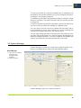
1
Esko Proof
Reference Guide
Copyright
© Copyright 2012 Esko Software BVBA, Gent, Belgium
All rights reserved. This material, information and instructions for
use contained herein are the property of Esko Software BVBA. The
material, information and instructions are provided on an AS IS basis without warranty of any kind. There are no warranties granted or
extended by this document. Furthermore Esko Software BVBA
does not warrant, guarantee or make any representations regarding
the use, or the results of the use of the software or the information
contained herein. Esko Software BVBA shall not be liable for any direct, indirect, consequential or incidental damages arising out of the
use or inability to use the software or the information contained
herein.
The information contained herein is subject to change without notice. Revisions may be issued from time to time to advise of such
changes and/or additions.
No part of this document may be reproduced, stored in a data base
or retrieval system, or published, in any form or in any way, electronically, mechanically, by print, photoprint, microfilm or any other
means without prior written permission from Esko Software BVBA.
This document supersedes all previous dated versions.
PANTONE®, PantoneLIVE and other Pantone trademarks are the
property of Pantone LLC. All other trademarks or registered trademarks are the property of their respective owners. Pantone is a
wholly owned subsidiary of X-Rite, Incorporated. © Pantone LLC,
2012. All rights reserved.
This software is based in part on the work of the Independent JPEG
Group.
Portions of this software are copyright © 1996-2002 The FreeType
Project (www.freetype.org). All rights reserved.
Portions of this software are copyright 2006 Feeling Software,
copyright 2005-2006 Autodesk Media Entertainment.
Portions of this software are copyright ©1998-2003 Daniel Veillard.
All rights reserved.
Portions of this software are copyright ©1999-2006 The Botan
Project. All rights reserved.
Part of the software embedded in this product is gSOAP software.
Portions created by gSOAP are Copyright ©2001-2004 Robert A.
van Engelen, Genivia inc. All rights reserved.
2
C
Copyright
Portions of this software are copyright ©1998-2008 The OpenSSL
Project and ©1995-1998 Eric Young ([email protected]). All rights
reserved.
This product includes software developed by the Apache Software
Foundation (FM MARKER [Hypertext] message URL http://
www.apache.org/http://www.apache.org/).
Adobe, the Adobe logo, Acrobat, the Acrobat logo, Adobe Creative
Suite, Illustrator, InDesign, PDF, Photoshop, PostScript, XMP and
the Powered by XMP logo are either registered trademarks or trademarks of Adobe Systems Incorporated in the United States and/or
other countries.
Microsoft and the Microsoft logo are registered trademarks of Microsoft Corporation in the United States and other countries.
SolidWorks is a registered trademark of SolidWorks Corporation.
Portions of this software are owned by Spatial Corp. 1986 2003. All
Rights Reserved.
JDF and the JDF logo are trademarks of the CIP4 Organisation.
Copyright 2001 The International Cooperation for the Integration of
Processes in Prepress, Press and Postpress (CIP4). All rights reserved.
The Esko software contains the RSA Data Security, Inc. MD5 Message-Digest Algorithm.
Java and all Java-based trademarks and logos are trademarks or
registered trademarks of Sun Microsystems in the U.S. and other
countries.
Part of this software uses technology by BestTM Color Technology
(EFI). EFI and Bestcolor are registered trademarks of Electronics For
Imaging GmbH in the U.S. Patent and Trademark Office.
Contains PowerNest library Copyrighted and Licensed by Alma,
2005 – 2007.
All other product names are trademarks or registered trademarks of
their respective owners.
Correspondence regarding this publication should be forwarded to:
Esko Software BVBA
Kortrijksesteenweg 1095
B – 9051 Gent
[email protected]
3
Table of Contents
Chapter 1. Copyright ...............................2
Chapter 2. Table of Contents ..................4
Chapter 3. Introduction ...........................6
3.1. What is Esko Proof? ..................................................... 6
3.2. Program architecture .................................................... 6
3.3. System requirements .................................................... 7
3.4. Program folders ............................................................ 8
3.5. About this manual ....................................................... 12
3.6. Conventions ............................................................... 12
Chapter 4. Setting up ............................14
4.1. Starting the Esko Proof Client ..................................... 14
4.2. Logging on to an Esko Proof Server ........................... 14
4.3. System workflows ...................................................... 16
4.3.1. Default system workflows .................................. 16
4.3.2. Setting up system workflows ............................. 16
Chapter 5. Getting to know your software
28
5.1. Job Explorer ............................................................... 28
5.2. System Manager ........................................................ 29
Chapter 6. Settings in System Manager 32
6.1. Menus ........................................................................ 32
6.1.1. File menu .......................................................... 32
6.1.2. Edit menu .......................................................... 33
6.1.3. System menu .................................................... 36
6.1.4. Tools menu ....................................................... 36
6.1.5. “?” menu (Windows)/Help menu (Macintosh) ..... 36
6.2. Toolbar ....................................................................... 37
6.3. Property Inspector ...................................................... 37
6.3.1. User settings ..................................................... 38
6.3.2. Workflow settings .............................................. 38
6.3.3. Output device settings ...................................... 64
Chapter 7. Managing system workflows 70
7.1. Making changes to system workflows ........................ 70
7.1.1. Available menu commands ............................... 70
7.2. Saving and restoring settings ...................................... 73
Chapter 8. Settings in Job Explorer ......80
8.1. Menus ........................................................................ 80
8.1.1. File Menu .......................................................... 80
8.1.2. Edit menu .......................................................... 81
8.1.3. Nesting menu .................................................... 86
8.1.4. Tools menu ....................................................... 87
8.1.5. View menu ........................................................ 87
8.1.6. “?” menu (Windows)/Help menu (Macintosh) ..... 90
8.2. Context menus ........................................................... 90
4
8.3. Toolbars ..................................................................... 92
8.3.1. First toolbar ...................................................... 92
8.3.2. Second toolbar ................................................. 92
8.3.3. Preview toolbar ................................................. 94
8.4. Property Inspector ...................................................... 95
8.4.1. Input tab > Info pane ........................................ 95
8.4.2. Input tab > Settings pane .................................. 95
8.4.3. Layout tab > Job Layout pane .......................... 95
8.4.4. Layout tab > Nesting pane ................................ 96
8.4.5. Layout tab > Step & Repeat pane ..................... 96
8.4.6. Layout tab > Footer pane ................................. 96
8.4.7. Finishing tab > Marks pane ............................... 97
8.4.8. Output tab > Print pane .................................... 97
8.4.9. Output tab > Special pane ................................ 97
8.4.10. Output tab > File output pane ......................... 97
8.4.11. System tab > Server pane .............................. 97
8.4.12. System tab > Device pane .............................. 98
8.5. Keyboard shortcuts .................................................... 98
8.5.1. Activating options ............................................. 98
8.5.2. Activating toolbars ............................................ 98
8.5.3. General ............................................................. 99
8.5.4. Page position .................................................. 100
8.5.5. Nesting jobs.................................................... 100
8.5.6. Zoom .............................................................. 101
8.5.7. Rulers, guides and grid ................................... 101
Chapter 9. Printing and monitoring print
jobs ..................................................... 104
9.1. Printing directly from Esko Proof .............................. 104
9.2. Job Monitor .............................................................. 107
9.2.1. Menus ............................................................ 109
9.2.2. Printing via Job Monitor .................................. 111
9.3. Printing via a hotfolder .............................................. 112
Chapter 10. Nestings ......................... 116
10.1. What are nestings? ................................................ 116
10.2. User interface ......................................................... 117
10.3. Creating nestings ................................................... 118
10.3.1. Automatic nestings ....................................... 118
10.3.2. Manual nestings ............................................ 119
10.4. Editing nestings ...................................................... 120
10.4.1. Adding jobs to a nesting ............................... 120
10.4.2. Adding/deleting sheets ................................. 120
10.4.3. Removing jobs from nestings ........................ 120
Chapter 11. Esko Proof Control ......... 122
11.1. What is Esko Proof Control? .................................. 122
11.2. Available features ................................................... 122
11.2.1. Esko Proof Server Stop/Esko Proof Server Start/
Esko Proof Server Restart ..................................................... 122
11.2.2. Esko Proof Client Start .................................. 123
11.2.3. Esko Proof Server Configuration (Windows only) .
T
Table of Contents
123
11.2.4. Autostart Esko Proof Control (Windows)/Open at
Login (Macintosh) ................................................................... 123
11.2.5. Exit (Windows)/Quit (Macintosh) .................... 123
Chapter 12. LinTool ............................126
12.1. What is LinTool? ..................................................... 126
12.2. How does color management work in Esko Proof? . 126
12.2.1. Profiles .......................................................... 126
12.2.2. Base Linearization ......................................... 127
12.3. System Manager settings ....................................... 127
12.4. Starting LinTool ...................................................... 128
12.5. User interface ......................................................... 129
12.5.1. Menus ........................................................... 130
12.6. Working with LinTool .............................................. 130
12.7. LinTool and Color Engine Pilot ................................ 131
12.7.1. Tips ............................................................... 131
Chapter 13. Troubleshooting ..............134
13.1. Server/Logging on .................................................. 134
13.2. Printing ................................................................... 136
13.3. Media profiles ......................................................... 139
13.4. USB devices ........................................................... 140
13.5. Support .................................................................. 141
Chapter 14. Uninstalling ......................142
Chapter 15. Glossary ..........................146
Chapter 16. Index ................................152
5
Chapter 1: Introduction
This is a brief introduction to Esko Proof. It describes the purpose
for which the software was designed, provides details of the hardware and software requirements necessary to set up and run your
software and gives an overview of the folder structure.
1.1 What is Esko Proof?
Esko Proof is the perfect tool for anyone wanting to achieve highquality color reproduction. The software runs on both Windows and
Macintosh, is easy to use and produces color-accurate output,
while avoiding the need for complicated color management settings.
The standard media and simulation profiles provided with the software enable your printer to simulate the colors achieved on a professional printing press, thereby making it possible to reproduce
genuine proofs on a conventional printer.
In addition, the software includes many settings that are essential in
the production industry for modifying photographic images.
Esko Proof is, therefore, ideal for printing houses, designers, photographers, agencies and service providers in the print media industry, for whom predicting color-accurate print results constitutes
an important part of their daily work.
1.2 Program architecture
Esko Proof is based on a Server/Client architecture of modular design. A Server version installed on one computer can be accessed
from an unlimited number of Client versions installed on the same
or on any other computer. This allows users maximum flexibility in
customizing the software to suit their own particular workflow requirements.
The minimum version of the software comprises:
6
1
Introduction
• Esko Proof (includes one Server version and an unlimited
number of Client and Job Monitor versions)
- The Server is the “brain” behind the software. It runs as a
service and is responsible for job processing. When you
restart your computer after installing the software, the Server
software starts automatically.
- The Client software simply provides an intuitive user interface.
All settings and actions initiated on the Client computer are
sent to the Server for processing.
• One Output M Option (for one printer)
However, a Verification add-on module is available to supplement
the standard version.
1.3 System requirements
The following recommended system requirements are necessary to
install and run Esko Proof successfully.
• Operating systems
Windows
• Windows XP Home Edition
• Windows XP Professional
• Windows 2003 Server standard
• Windows Vista
• Windows 2008 Server
Macintosh
• Mac OS X 10.4 and 10.5
7
• Hardware
Server
• PC: 2 GHz Pentium IV PC or higher (dual processor
recommended)
• Macintosh: Intel Mac (dual processor
recommended)
• 1 GB RAM for each processor
• 60 GB free hard disk space(*)
• 10/100 MBit network interface card
• 2 available USB ports (for dongle and measuring
device)
Client
• PC: 2 GHz Pentium IV PC
• Macintosh: Intel Mac or PowerPC processor G4,
G5
• 512 MB RAM
• 10/100 MBit network interface
• 1 available USB port (for measuring device)
Note:
(*) You must have 60 GB of free hard disk space on the drive where
your Documents and Settings folder is located (typically the C:/ drive).
This is because all work files directly associated with job processing
are located in your Documents and Settings folder.
1.4 Program folders
This section gives an overview of the file structure of Esko Proof to
enable you to locate program files, custom files and other important
files quickly and easily.
• Installation folder
Unless you choose a different location, fixed program
components of Esko Proof are installed by default in the
following folder:
8
Windows XP/2003/
2008/Vista
\Program Files\Esko\Esko Proof
Macintosh
/Applications/Esko Proof
1
Introduction
The application folder contains the following four subfolders:
Folder name
Subfolder name
Client
Contains
Program files for Esko
Proof, including additionally licensed options
Color Manager Charts
Charts for linearization
Color Verifier Charts
Charts for checking color
accuracy in Esko Verifica-
tion
Documentation
HTML Help files and PDF
user manual
IT8_CharacterizationDat
a
IT8.7/4 profiling charts for
Fogra Proof Certification
MonitorProfile
Default and custom monitor profiles
Samples
Lineal_01.ps for calculating
media length correction
Monitor
Program files for Job Monitor
Server
All program files related to
the Server
Tools
Program file for Esko Proof
Server Information
Definition Strip for X-Rite
DTP-20
TIDforMKV2OXP-V2.tif (TID
patch for DTP 20 measuring device)
FograCert
FograCert proof creation
test forms
USB Measurement
Devices
Device drivers for supported measuring devices
• Work folder
You will find all work files directly associated with job processing
located in the following folders:
Windows 2000/XP
\Documents and Settings\All Users\Application
Data\Esko\Esko Proof
Windows Vista/2008
\ProgramData\Esko\Esko Proof
Macintosh
/Library/Application Support/Esko/Esko Proof
9
If you cannot see the Application Data folder, it may be because
it is set up as a hidden folder on your computer. Consult your
administrator if you have trouble accessing this folder.
The Esko Proof folder contains the following folders and
subfolders:
Folder name
Client
10
Subfolder name
Working
Contains
Temporary files. Used to
save linearization files from
LinTool as well as
Remoteproof Containers for
manual creation.
Introduction
Folder name
Server
Subfolder name
Contains
Backup
Backup files of system workflows
ControlCharts
Control strips for HP Zx100
printers
ControlStrip
Control strips for footer
Environments
Backup files of environments
Export
Default folder for print-to-file
jobs
JobFolder
Temporary job files
Log
Log files. Important in case
of support queries.
Logo
Copies of logo files selected
for job ticket
Output
Print (bco) files
Preview
Preview files
Profiles
\Balance
\Monitor
\Reference
\Reference Additional
\Spotcolor
Default 3cc files
Monitor profiles
Reference profiles in common use in the industry
Device link profiles
Additional reference profiles
in common use around the
world
Spot color tables (bct) created in Spot Color Editor
Remote
Incoming and outgoing
Remoteproof Containers
(rpf) to and from Esko Verification
Tickets
Record of all actions taken in
Esko Proof. Important in
case of support queries.
• Media profiles
Media profiles are installed in the following folders:
Windows XP/2003/
2008/Vista
\Program Files\Esko\Esko Profiles
Macintosh
/Library/Application Support/Esko/Esko Profiles
11
1
1.5 About this manual
Users of this manual should already be familiar with:
• The operating system on which their software is installed
• The subject of color management
1.6 Conventions
Cautions must be read carefully. They indicate permanent actions
which, once executed, cannot be undone.
Tips and information which you may find useful.
The screen captures illustrated in this manual have been created
from a mixture of both the Windows and Macintosh versions of the
software. Depending on which version you are using, the image on
your screen may look slightly different. However, unless otherwise
stated, the functionality is the same for both operating systems.
12
Introduction
13
1
Chapter 2: Setting up
2.1 Starting the Esko Proof Client
To start the Esko Proof Client:
• Double-click the program icon on the computer desktop
(Windows)
• Click the program icon in the Dock (Macintosh)
Program icon
The software cannot be started before it is licensed.
2.2 Logging on to an Esko Proof Server
If an Esko Proof Server and Client are installed on the same computer, the Esko Proof Client automatically logs on to that Server as
the default administrator the first time you start the software. If no
Esko Proof Server is installed on the same computer, the following
window opens when you try to start the software. You must log on
to an Esko Proof Server before you can proceed.
Login window
14
Setting up
If a firewall is in use in your network, make sure that it is configured
so that communication between Server and Client computers is
possible. The following ports must be available on the Server and
Client computers:
• 8010 (TCP and UDP)
• 50005 to 500025 (TCP and UDP)
Furthermore, make sure that the following applications can communicate with the network:
Server
Esko_Proof_Server.exe
Esko_Proof_Control.exe
Client
Esko_Proof_Client.exe
Esko_LinTool.exe
Esko_Verification.exe
For the Windows firewall, the port and application settings are created automatically by the installer.
TO LOG ON TO AN ESKO PROOF SERVER
1 Type the default login information, as follows:
User name: admin
Password: admin
This is the default administrator login information. You can log in as
a different user if Esko Proof has already been set up and
additional users have been created.
2 Select the IP address of the Server computer.
A list of all available Esko Proof Servers in your sub-network is
displayed with IP address in the drop-down list. If Server and Client
are installed on the same computer, the IP address of the local
Server is placed first in the list. However, you can also type in
manually the IP address of an Esko Proof Server. Ask your system
administrator if you are not sure which TCP/IP address to use.
If you are currently logged on to a Server on a different computer
and want to log on to a local Server installed on the same
computer as the Esko Proof Client, you can type “localhost”
instead of an IP address. This means that the default IP address
127.0.0.1 is used by the software.
3 Click OK.
The connected Server is displayed at the bottom of the program
window.
15
2
2.3 System workflows
This documentation makes a distinction between the terms “system
workflow” and “workflow”. The term “system workflow” consists of
a user, workflow and output device. It refers to all work processes
from file input by a certain user to file output on a specified printer.
The term “workflow” is concerned only with file processing and the
way files are handled in Esko Proof.
2.3.1 Default system
workflows
Esko Proof is installed with one default system workflow, consisting
of two users, one workflow and one output device.
Default system workflow
configuration
The user “admin” (default password “admin”) is permitted to create,
set up and manage system workflows in System Manager.
The user “guest” (default password “guest”) is permitted to print
and manage his or her own print jobs in Job Explorer but does not
have access to System Manager and cannot create or modify system workflows. “Guest” enables infrequent users of Esko Proof to
log on quickly and easily, without first having to be defined as an individual user.
The workflow “Esko Linearization” and the output device “Linearization device” are used primarily in conjunction with Esko LinTool for
printer linearization. Only users with administrator rights can print
jobs via this workflow.
You must configure the linearization device before you can access
Esko LinTool.
If you set up a workflow and output device as part of the installation
procedure, these will also be visible in System Manager.
2.3.2 Setting up system
workflows
You can set up a system workflow in:
• Setup Wizard (Windows) or Setup Assistant (Macintosh)
The Setup Wizard/Assistant leads you logically through the
minimum of steps necessary to set up a system workflow for the
default users. You can fine tune your workflow settings later in
System Manager, if required.
Normally, you will already have created a system workflow in this
way when you installed Esko Proof.
16
Setting up
• System Manager
In System Manager, you can create additional users, workflows
and output devices. You can also change the configuration of
existing workflows.
To set up an output device, you must have media profiles for your
printer installed on the computer. If you did not install any media
profiles during program installation, install them now from the
software DVD.
• Setting up in Setup Wizard/Assistant
Setup Wizard/Assistant provides step-by-step instructions on how
to configure a basic system workflow.
TO SET UP A SYSTEM WORKFLOW IN SETUP WIZARD/ASSISTANT
You can click Finish Now at any time to exit the setup procedure.
Any settings that you have already made are saved.
1 In the toolbar, click System Manager.
2 From the System menu, choose Setup Wizard (Windows)
or Setup Assistant (Macintosh).
Introduction window
17
2
3 Click Continue to open the Workflow dialog.
Creating a workflow
4 Select “Create new”.
5 From the drop-down list “Template”, choose a workflow
template that best suits your needs.
When you make a selection from the list, the individual template
settings are displayed.
18
Setting up
6 Click Continue to display the Output device dialog.
Selecting an output
device
7 From the drop-down list, select “Create a new output
device”.
8 From the drop-down list, select your output device.
When you make a selection, the Setup Wizard/Assistant displays
the number of media profiles installed for the output device.
If no media profiles are installed, an error message is displayed. In
this case, you must cancel the setup and install the appropriate
media profiles from the software DVD.
19
2
9 Click Continue to open the Device connection dialog.
Setting up a connection
20
Setting up
10 Select a connection type.
• Select “Print to system printer” to print to a Windows printer that
has already been set up as a system printer in Windows.
The available printers are listed in the drop-down list.
This setting is only available for Windows and the system printer
must be a printer supported by Esko Proof.
• Select “Print via IP network” if you want to print via TCP/IP.
Type the IP address in the appropriate edit box. You can check
whether the connection to the printer has been properly
established by clicking Test. To test the connection, the printer
must be switched on. If you receive an error message, consult
your system administrator for advice.
Select the type of TCP/IP protocol that your printer uses for data
transfer.
- Raw on port
Most printers support RAW printing to port 9100. However,
please note that this setting depends on the network settings
made at the printer and may, therefore, be different.
- LPR. The queue name is
If your printer supports LPR printing, type the queue name in
the edit box.
In most cases, you can leave this edit box blank. It is normally
only necessary to type a queue name if you are printing via a
Unix system or a print server with multiple interfaces. Refer to
your printer manual for further information.
• Select “Print via port” to print to a printer connected via USB to
the Server computer.
The printer must be switched on when you start Esko Proof.
Otherwise, it will not be automatically detected.
21
2
11 Click Continue to open the Media type dialog.
Selecting a media type
12 From the drop-down list “Ink type”, select the type of ink
inserted in the printer.
13 From the drop-down list “Media name”, select the media
you want to use.
Esko Proof provides media profiles that have been created for
specific combinations of media, ink and resolution. Furthermore,
you can implement your own custom media profiles that have
been created for your exact printer.
14 From the drop-down list “Print quality”, select a
combination of color mode, resolution and print mode.
The list of available print qualities depends on the media profiles
that are installed.
22
Setting up
15 Click Continue to open the Media size dialog.
Selecting a media size
16 In the Media Size dialog, make media-specific settings.
Which settings are available depends on the selected printer.
• From the drop-down list “Source”, select the source of media
feed.
• From the drop-down list “Format”, select the media size. Only
default sizes are available initially, but you can define your own
media sizes in Esko Proof.
• If supported by your particular printer, you can select borderless
printing.
17 Click Finish.
Your workflow and output device are now set up.
• Setting up in System Manager
Creating system workflows in System Manager gives you access to
all the settings available in Esko Proof.
Once you have created a system workflow, you need to set it online.
TO CREATE A NEW USER
You can set up each co-worker as a user in Esko Proof and define
user privileges for each.
23
2
1 Create a new user by:
• Clicking New User in the toolbar, or
• Right-clicking on an existing user in the layout area and choosing
New User from the context menu, or
• Choosing File > New > User
A user with the name “New User 1” is created. The User tab
displays the Profile pane.
2 Define a name for the user by:
• Double-clicking on “New User 1” in the layout area, overwriting
the default name and pressing <Enter>, or
• Overwrite “New User 1” on the Profile pane
3 On the Profile pane, define a password. Then confirm it by
re-typing it in the appropriate edit box.
4 Using the drop-down list, specify whether the new user
will have administrator or user rights.
Administrators have access to System Manager and are permitted
to create, set up and manage workflows. Users without
administrative rights are only able to submit print jobs and make
job-specific settings in Job Explorer.
5 Define whether the new user will be allowed to define
verification settings.
6 In the toolbar, click Save.
24
Setting up
TO CREATE A WORKFLOW
1 Create a new workflow by:
• Clicking New Workflow in the toolbar, or
• Right-clicking on an existing workflow in the layout area and
choosing New Workflow from the context menu, or
• Choosing File > New > Workflow
The window New Workflow from Template opens.
New Workflow from
Template dialog
2 Highlight a template in the list.
Initially only the default workflows are available as templates.
However, once you have created your own workflows, you can
save them and add them to the list. Workflow templates are saved
with all the settings defined for the original workflow and serve as
the basis for new workflows with similar properties. This enables
you, for example, to use the same workflow settings to print to
different output devices, since each workflow can only be
connected to one printer at a time.
3 Click Load.
A new workflow with the name of the selected workflow template
is created, supplemented by a consecutive number.
4 Define a unique name for the workflow by:
• Double-clicking on the new workflow in the layout area,
overwriting the default name and pressing <Enter>, or
• Overwriting the default name on the General pane of the
Workflow tab
25
2
5 Type a brief workflow description, if required.
The default settings are automatically displayed, but you can add
any additional information.
6 Define your preview and file deletion settings, if required.
7 Check the settings which affect the processing and print
speed of your jobs.
8 On the remaining tabs, make any additional settings.
For example, on the Layout tab, you can set up your workflow for
automatic nesting or step & repeat.
9 When you are finished, save your workflow by clicking
Save in the toolbar.
To save your newly created workflow as a basis for further workflows, choose Save as Template from the File menu and define a
name.
The next time you create a new workflow, it will be displayed in the
window “New Workflow from Template”.
TO CREATE A NEW OUTPUT DEVICE
1 Create a new output device by:
• Clicking New Output Device in the toolbar
• Right-clicking on an existing output device in the layout area and
choosing New Output Device from the context menu, or
• Choosing File > New > Output Device
2 Set up the new output device.
See also:
“User settings” on page 38
“Workflow settings” on page 38
“Output device settings” on page 64
• Setting system workflows online
When you have created a system workflow, the next step is to set
it online.
When a workflow is fully online, all jobs are automatically processed
and printed as soon as they are loaded in Esko Proof.
26
Setting up
TO SET A SYSTEM WORKFLOW ONLINE
1 Check that your system workflow is properly connected.
Users, workflow and output must be visibly joined by a black line.
Connected system
workflows depicted by a
black line
To connect two objects, click object one (e.g. user) and drag the
cursor across to object two (e.g. workflow). Make sure to drag the
cursor from the margin area of an object. Dragging from the center
rearranges the order in which your users, workflows or output
devices are displayed.
2 Check that your system workflow is online.
A fully online system workflow is indicated by green arrows from
user through to output device.
See also:
“Making changes to system workflows” on page 70
27
2
Chapter 3: Getting to know your software
The user interface of Esko Proof is divided into the following two
program windows, which you display by clicking the appropriate
button in the program window bar:
• Job Explorer (administrators and users)
Here you load and apply settings to your print jobs.
• System Manager (administrators only)
Here you set up and configure your workflows and printers,
create users and grant them access rights to print via specific
workflows.
3.1 Job Explorer
Job Explorer is where you load, organize and preview jobs, and
make job settings.
Job Explorer
1 Menu bar
2 Toolbars
3 Job list
4 Property inspector
5 Preview window
6 Selector
1
2
6
5
3
28
4
Getting to know your software
The job list provides an overview of loaded jobs. A selected job is
previewed in the preview window and you can configure job-specific settings in the property inspector.
The Selector acts as filter, listing jobs according to workflow, output
device or job status. The button “All Jobs” lets you view all your jobs
in the job list.
The job list contains job-specific information, such as job status and
job name. Each job status is indicated by a different color.
You can add or remove columns to display the information that is
most important to you by right-clicking on a column heading and
choosing the required items from the context menu.
You can also change the order of the columns in the job list by holding down the mouse button on a column heading and dragging to
the left to a different position. The column heading “Job Status” and
“Name” are fixed and cannot be repositioned or removed.
3.2 System Manager
System Manager is where you create and configure system workflows. It is available only to users with administrator status.
System Manager
1 Layout area for creating,
configuring and
managing system
workflows
2 Property inspector
1
2
System Manager gives you a clear overview of:
29
3
• which users can print to which workflows
• the output device assigned to each workflow
In System Manager, you can halt jobs at certain stages of the workflow. This may be desirable to perform certain tasks. For example,
a workflow can be diverted quickly and easily to another output device if a particular printer needs servicing.
The changes you make in this window are applied to all jobs in the
job list that have not yet been processed.
See also:
“Setting system workflows online” on page 26
30
Getting to know your software
31
3
Chapter 4: Settings in System Manager
These sections describe the individual settings concerned with creating and setting up system workflows. They deal only with those
settings available in the basic software configuration. Settings related to add-on modules are dealt with in the respective sections.
4.1 Menus
4.1.1 File menu
• New
- User
Choose this command to add a new user.
- Workflow
Choose this command to create a new workflow that is based
on one of the default workflow templates or on any other
workflow that you have previously saved as a workflow
template.
- Output Device
Choose this command to create a new output device.
• Import Environment
Choose this command to load a backup file of your system
workflow environment.
• Save
Choose this command to save all the changes made to the
system workflow.
• Save as Template
Choose this command to save a new workflow template you
have created under any chosen name. Workflow templates form
the basis for new workflows with the same or similar settings.
• Save as Environment
An environment is a combination of workflow and printer.
Choose this command to create a backup copy of your workflow
and printer settings.
32
Settings in System Manager
• Backup
Choose this command to create a backup copy of your system
workflows.
• Restore
Choose this command to restore a previously backed up copy of
your system workflows.
• Login
Choose this command to display the “Login” dialog. This
command enables you to log in under a different user name or to
log on to a different Server.
• Logoff and Exit
Choose this command to log off and exit the Esko Proof Client.
The next time you start Esko Proof the “Login” dialog opens.
It is advisable to log off with this command if more than one
person is using the same computer. This ensures that each user
logs on to his own workflow settings.
• Exit (Windows)/Quit Esko Proof (Macintosh)
Choose this command to exit Esko Proof. The next time you
start Esko Proof you will automatically be logged on with the
same user data.
In the Macintosh version of the software, you will find the
command in the Esko Proof menu.
4.1.2 Edit menu
• Languages (Windows only)
Choose this command to change the language in which the user
interface is displayed. You must restart the Esko Proof Client
before the new language takes effect. By default, the language
of the operating system is displayed.
On a Macintosh, you can change the language the international
settings in “System Preferences”.
If you change the display language, make sure that the help set
for that language is installed. Otherwise, no help will be available
from the Help menu. You can install help sets in additional
languages from the software DVD.
Please note that to display one of the supported Asian
languages on a PC, Esko Proof must be running on an operating
system that supports 2-byte fonts.
33
4
• Measurement system
Choose this command to define which system of measurement
is used in Esko Proof. The default setting corresponds with the
system of measurement set up in the operating system.
However, you can choose between millimeter, centimeter,
meter, inch and foot.
• Monitor Profile
Esko Proof provides you with the opportunity to verify color
accuracy on a computer screen. This is known as “soft
proofing”. However, much like the color output of each printer
can vary greatly, so each monitor displays color slightly
differently. To overcome this problem, it is important that the
monitor is regularly calibrated to a certain standard. Monitor
calibration consists of two steps:
- adjusting the brightness and control settings on the monitor
itself to set values and
- creating a monitor profile, which defines the white point,
gamma and RGB phosphor settings
Windows and Macintosh computers provide standard monitor
profiles as part of the operating system software. In Esko Proof
you can select a monitor profile that you have created yourself or
one provided with the operating system.
• Copy
Choose this command to copy a selected user, workflow or
output device to the clipboard.
• Paste
Choose this command to insert a duplicate of a user, workflow
or output device from the clipboard.
• Delete
Choose this command to delete the selected user, workflow or
output device.
• System
This command enables you to make global settings to connect
and disconnect users, workflows and output devices to and
from a system workflow.
34
Settings in System Manager
• User
This command contains user-related settings which enable you
to:
- Check which workflows a selected user is connected to
- Check if the selected user is online/offline
- Connect the selected user to all workflows
Users with no administrator rights cannot be connected to the
Esko Linearization workflow.
- Disconnect a selected user from all workflows
- Create a new user
- Delete the selected user
• Workflow
This command enables you to:
- View which users are connected to the selected workflow
- View which output device is connected to the selected
workflow
- Set up a connection from user to workflow so that user can
load jobs in Esko Proof
- Set up a connection to an output device so that jobs can be
processed and printed
- Connect all users to the selected workflow
- Disconnect all users from the selected workflow
- Disconnect the output device from the workflow
- Save a system workflow as an environment
- Create a new workflow
- Delete a selected workflow
• Output Device
This command enables you to:
- View which workflows are connected to the selected output
device
- Check if a selected output device is online/offline
- Linearize/re-linearize an output device. When you choose the
appropriate commands, the configuration of the selected
35
4
printer is automatically transferred to the linearization device
and LinTool is started.
- Connect all workflows to the selected output device
- Disconnect the selected output device from all workflows
- Create a new output device
- Delete a selected output device
4.1.3 System menu
• Setup Wizard (Windows)/Setup Assistant (Macintosh)
Leads you step by step through the settings necessary to create
new system workflows or to make changes to existing ones.
• Clean Up
Choose this command to delete files that are no longer needed.
You can choose to delete output files, preview files, temporary
files, files loaded in the job list and log files. Alternatively, select
“All” to delete all.
4.1.4 Tools menu
• Open Esko LinTool
Choose this command to start Esko LinTool (default tool) — a
tool for ensuring your printer’s color consistency.
• Job Explorer
Choose this command to switch to Job Explorer.
A command for starting Esko Verification is also available if you have
a valid license for it.
4.1.5 “?” menu (Windows)/
Help menu (Macintosh)
• Help
Choose this command to start the HTML online Help for Esko
Proof.
If you change the display language, make sure that the help set
for that language is installed. Otherwise, no help will be available
from the Help menu. You can install help sets in additional
languages from the software DVD.
• About
Choose this command to open a window with details of your
program version.
In the Macintosh version of the software, you will find the
command in the Esko Proof menu.
36
Settings in System Manager
4.2 Toolbar
New User:
Click this button to add a new user.
New Workflow:
Click this button to add a new workflow to the system workflow.
New workflows are based on previously saved workflow templates.
New Output Device:
Click this button to add a new printer.
Save:
Click this button to save your settings.
Delete Selected Object:
Click this button to delete a selected item.
Open LinTool:
Click this button to start Esko LinTool (default tool) — a tool for ensuring your printer’s color consistency.
Job Explorer:
Click this button to switch to the program window “Job Explorer”
where you load and process jobs.
System Manager (this window) (for users with administrative rights
only):
Click this button to display the program windows “System Manager” where you set up system workflows.
4.3 Property Inspector
The Property Inspector displays the settings of a selected:
• user
• workflow or
• output device
All the settings you make in System Manager are made for a selected workflow and are applied to all jobs processed via that workflow.
Job-specific settings are possible in Job Explorer, which override
the settings made in System Manager.
The Info pane on the Server tab is accessible from all areas of System Manager. It displays information about current system utilization and the job status of all jobs. It also displays the amount of used
hard disk space on your computer.
Esko Proof requires a certain amount of free disk space. Be aware
that if less than 2.5% free disk space is available, you may not be
able to load and process jobs in Esko Proof.
37
4
4.3.1 User settings
The users settings are available when you select a user in the layout
area.
• User tab > Profile pane
• User name
Use this edit box to type a name for a new user or change the
name of an already defined user.
• Password
Define a password. Note that passwords are case-sensitive.
Confirm the password by retyping it in the appropriate edit box
and clicking Apply.
You may change the password of the default administrator if you
wish. However, please note that if the default administrator is the
only user with administrator rights and the password is
misplaced, you will no longer be able to access the software to
make settings at administrator level.
• User role
Select whether the user will have administrator or user rights.
Users with administrative rights have access to System Manager
and are permitted to create, set up and manage workflows.
Users with no administrative rights are only able to submit print
jobs and make job-specific settings in Job Explorer.
• Privileges
The rights of all users can be extended to allow them to make
job settings for color verification and finishing (crop marks and
contour cutting).
4.3.2 Workflow settings
The workflow settings are available when you select a workflow in
the layout area.
• Workflow tab > General pane
• Name
Type a name for a new workflow or change the name of an
already defined workflow. It is not possible to change the name
of the default linearization workflow.
38
Settings in System Manager
• Description
The Description box gives details of some of the more important
settings of the template used to create the workflow. You can
edit the text to reflect changed settings or add comments.
• Preview settings
- Create previews (even if the workflow is offline)
Select this setting if you want to display an automatic preview
of all loaded print jobs. If this setting is set to off, you can still
create job-specific previews in Job Explorer.
- Resolution
Select a radio button to define the resolution of a displayed
preview in dpi or pixel.
• Source files
Use the drop-down list to choose when job files saved to the
JobFolder are automatically deleted. Files can be deleted:
- Never
- Automatically after printing
- After a specified number of days. Type the time span in days
in the edit box.
Any setting you make for source file deletion is automatically
applied to output/preview files. It is not possible to delete source
files alone.
• Delete source files from hotfolder
Select this check box to delete job files copied to a hotfolder.
39
4
• Output/preview files
During job processing, Esko Proof creates a print file of each job
and saves it to the Output folder. If the preview function is
activated for the workflow, a preview file is also saved to the
Preview folder. Use the drop-down list to choose when output
and preview files saved to these folders are automatically
deleted. Files can be deleted:
- Never
- Automatically after printing
- After a specified number of days. Type the time span in days
in the edit box.
If you have previously made a setting to delete source files, the
same setting is automatically applied to output/preview files. An
independent setting is only possible if you have specified that
source files are never to be deleted.
• Speed
- High priority workflow
Select this check box to ensure that all jobs printed via this
workflow go straight to the front of the print queue, i.e. if more
than one workflow is printing to the same printer, all jobs
received via a high-priority workflow will be output first.
- Bi-directional
If your printer supports this feature, select the check box to
increase print speed. Bi-directional printing is faster than
unidirectional printing, as the print head prints in both
directions, but may provide less accurate results.
Please note that some settings in the linearization may be
overwritten.
- RIP and print on the fly
Select this check box if you want your jobs to start printing as
soon as processing starts. If this check box is not selected,
printing will not commence until job processing has been fully
completed.
Simultaneous processing and printing may cause the printer
to pause from time to time. This can lead to undesirable lines
on the printout.
40
Settings in System Manager
• RIP Resolution
Use the slidebar to define whether speed or quality is the more
important factor during processing. By reducing the resolution at
which the print job is processed you increase the speed of
output.
Processing a print job at a low resolution may result in a draftquality output, whereas printing at a high resolution setting will
take longer. It is not possible to process a print job at a higher
resolution than the output resolution.
• Input tab > General pane
To enable job detection settings, you must first set the workflow offline. To do so, click on the green arrow at workflow entry. It becomes a red square to show that the workflow is offline.
• Hotfolder
Define the folder that is routinely monitored by Esko Proof for
incoming files. When new files are detected, they are
automatically loaded for processing.
A hotfolder in usually located in a network environment where it
can be accessed by any number of users who do not have the
Esko Proof Client installed on their computers.
The Esko Proof Server runs on Windows as a service. To enable
communication with hotfolders via the network, you need to
assign network access rights for the Esko Proof Server by
creating a user with administrative rights. See “Printing via a
hotfolder” on page 112.
If Server and Client are installed on the same computer, click
Choose to navigate to the folder you wish to use as a hotfolder.
A hotfolder can be located anywhere within an Esko Proof Server
installation folder or anywhere on the network.
Please be aware of the consequences of inadvertently defining
your computer desktop or a network drive as a hotfolder. This
will cause all the files saved to this location to be loaded.
If Server and Client are installed on different computers, you can
only print to hotfolders located inside the JobFolder of the Esko
Proof Server application folder.
It is recommended that you use a computer on which an Esko
Proof Server is installed to set up hotfolders.
41
4
• Enable load balancing
If the selected hotfolder is being monitored by more than one
workflow, you have to select this check box to instruct Esko
Proof to distribute the workload by diverting print jobs to the first
idle workflow that becomes available.
This ensures that print jobs are always output as quickly as
possible, e.g. if one workflow is busy processing a large-volume
print job or if one Server encounters a problem. Once a job starts
being processed, it is locked to other workflows. This prevents
jobs being processed by two workflows simultaneously.
The advantage of load balancing is that it utilizes all the available
system resources as efficiently as possible.
The following diagrams illustrate two possible scenarios for using
load balancing.
Example of load
balancing using different
Servers
Server
Server
Hotfolder
Server
42
Settings in System Manager
Example of load
balancing using different
workflows
Workflow_1
Workflow_2
Hotfolder
Workflow_3
Please note that workflows printing via the same hotfolder may
not necessarily be configured identically. This can result in
unsatisfactory color results if the workflow settings are different
or if a different printer is connected.
• Create Virtual Printer
This setting sets up a virtual printer for the workflow. It can be
selected from the print dialog of any application and thus
enables users to print directly to Esko Proof.
To set up a virtual printer, you must first define a hotfolder on this
pane. Then, select the check box and define a name for the
virtual printer. This is the name that will be displayed in the printer
list of the application.
The virtual printer is created when you switch the workflow online
at workflow entry.
43
4
• Import color management settings of remote job
- Use color management settings of remote job
Select this radio button if you are processing a Remoteproof
Container and wish to apply the color management settings
from the JDF file. In this case, the color management settings
defined for the workflow will be ignored.
- Use color management settings of workflow
Select this radio button if you are processing a Remoteproof
Container and wish to apply the color management settings
defined for the workflow. In this case, the color management
settings saved to the JDF file of the Remoteproof Container
will be ignored.
See also:
“Making changes to system workflows” on page 70
“Printing and monitoring print jobs” on page 104
“Printing via a hotfolder” on page 112
“Esko Proof Server Configuration (Windows only)” on page 123
44
Settings in System Manager
• Input tab > File Formats pane
• PS/PDF
- Stop job processing if font is missing
When you select this check box, job processing is halted if
Esko Proof detects a missing font. The missing fonts are
listed. However, you can still preview jobs correctly.
If the check box is left unchecked, print jobs with nonavailable fonts are output using the default font Courier
instead.
- Use size out of the:
You can specify which PDF setting is applied to calculate the
page size.
“Media box” describes the size of the output media and is
displayed in the print dialog. All the other boxes are smaller
and are found inside the media box.
“Crop box” defines the region to which the contents of the
page are to be clipped (or cropped) when displayed or
printed. Unlike the other boxes, the crop box has no defined
meaning in terms of physical page geometry or intended use.
It merely suggests where the page should be clipped.
“Bleed box” defines the bounds to which the contents of the
page should be clipped when output in a production
environment.
“ArtBox” defines the meaningful content of the page, including
potential white space.
“Trim box” defines the intended dimensions of the finished
page after trimming. This type of box is used by imposition
applications for arranging the order of pages.
45
4
PDF boxes
1 Media box
2 Bleed box
3 Trim box
4 ArtBox
4
1
2
3
- Calculate page size
Select this check box to instruct Esko Proof to calculate the
page size. This is done by RIPping the whole document at a
low resolution. It is slower than extracting the information from
the bounding box but produces more accurate results.
- Simulate overprinting in composite jobs
This check box enables you to determine whether overprint
settings defined in your image file are applied during printing.
Normally, when two objects of different colors overlap, there is
a knock-out effect, i.e. they will not print on top of each other.
Intentionally printing one layer of ink on top of another is
known as overprinting. Overprinting is sometimes used to
prevent gaps between adjoining colors.
This setting lets you simulate overprinting in composite jobs.
This would otherwise not be possible, since overprinting is not
supported by composite jobs.
By selecting the check box and examining the preview, you
can check the behavior of possible overprint settings in your
file before printing.
This setting has no effect on separated jobs.
- Working Color Space
Here you can define a color mode for your input data. For
example, if your PDF is composed mainly of RGB images,
select “RGB”. In this case, the RGB source profile selected on
46
Settings in System Manager
the “Color” tab is automatically applied to the entire PDF.
Similarly, selecting “CMYK” as the working color space
causes your PDF to be output using the selected CMYK
source profile. For proofing, you must use the CMYK working
color space.
CMYK workflow
RGB workflow
• EPS Job Detection
- Waiting time for job completion
This defines the time span during which Esko Proof waits for
incoming files that belong to a particular print job. Once this
time span has elapsed, the software assumes that all files
have been received and starts printing.
The default setting is five seconds. However, depending on
the size and type of your print jobs, you may wish to change
it. For example, for some large-volume separated jobs, a time
span of sixty seconds may be needed to ensure that all the
separations are received and processed as one print job.
Alternatively, for an EPS composite file a setting of one
second may well be sufficient to ensure that your print jobs
are output as quickly as possible.
- Default resolution
With this setting, you can override the default resolution of
72 dpi. Occasionally, Esko Proof has difficulty correctly
extracting and interpreting the resolution of incoming PS and
PDF files. Normally, 72 dpi is perfectly adequate. However, in
47
4
a very few cases, it is possible that rounding down errors may
occur due to internal processing in Esko Proof. This can
cause a white edge to be output along the right and bottom
edges of images, the result of missing pixels.
This is only really noticeable in step & repeat jobs, where a thin
white line may be visible between images, although no
spacing is defined.
To overcome the problem, Esko Proof provides the option to
define an input resolution of between 1 dpi and 720 dpi.
Selecting the input resolution size from the image helps to
prevent rounding off errors.
48
Settings in System Manager
• PDF print engine
- PDF PrintEngine
By default, print jobs are processed using the Adobe
PostScript 3 Engine, which converts source files first to
PostScript format. If your source files are in PDF format, you
can choose between “Adobe PostScript 3 Engine” and
“Adobe PDF Print Engine”. The Adobe PDF Print Engine
processes PDF files without converting them to PostScript
first.
- Image EPS/PDF print engine
This setting can be applied to a single EPS image saved in a
PDF frame.
PDF boxes
1 EPS image
2 PDF frame
1
2
The setting “Native” specifies that only the EPS image is
output, i.e. without the surrounding PDF frame.
The setting “Adobe PostScript 3 Engine” specifies that the
image file is output with the PDF frame. This setting is
automatically applied if the job contains more than a single
EPS image.
49
4
• Layout tab > Job Layout pane
• Sheet size
From the drop-down list, select whether you want to print:
- using the paper format set up for the output device or
- define a custom media size to override the setting made for
the output device. To define a custom media size, type the
required sheet dimensions in the appropriate edit boxes.
• Rotate
Select whether you want to rotate your print job. Choose from
“Do not rotate”, Rotate 90°, Rotate 180° or Rotate 270°. If you
select “Minimal media consumption”, Esko Proof will
automatically rotate your images, if necessary, to keep wastage
to a minimum.
• Mirror
Select the appropriate check box to print a horizontal or vertical
mirror image of your print jobs.
50
Settings in System Manager
• Scale page
Select a scaling factor from the drop-down list to define how
your print job will be adapted to the size of media you are using.
The following settings are available:
- Do not scale
With this setting, your image is printed in its original size. A
warning will be displayed if it will not fit fully on the media.
- Fit to page size
With this setting, your image is scaled so that either the height
or the width of your image is adjusted to the printable height
or width of the media.
- Fit to width
With this setting, your image is scaled horizontally so that the
width of your image is adjusted to the printable width of the
media.
However, this may mean that the height of your image is
clipped. You can check the preview to see what effect this
setting will have on the printed image and make sure that it
will fit properly on the selected media size.
- Fit to height
With this setting, your image is scaled vertically so that the
height of your image is adjusted to the printable height of the
media.
However, this may mean that the width of your image is
clipped. You can check the preview to see what effect this
setting will have on the printed image and make sure that it
will fit properly on the selected media size.
- Scale job percentually
With this setting, you can define an enlargement or reduction
factor for your image. A value of more than 100 increases the
size of your image, whereas a value of less than 100
decreases the image size. It is possible to define different
scaling factors for width and height. Please note that defining
different factors for width and height will result in a distorted
output of your image.
This setting is overridden by the uniform page scaling setting
on the Nesting pane.
51
4
- Scale job numerically
With this setting, you can define a new height and width for
your image.
This setting is overridden if uniform page scaling is defined on
the Nesting pane.
• Align
Choose an alignment setting by selecting the appropriate cell in
the diagram. For example, if you check the middle cell, your job
will be output centered horizontally and vertically on the selected
media. This setting takes job margins into account.
If the output device is set up to print on roll media, only horizontal
alignment is possible.
• Job margin
You can define margins for more precise positioning of images.
Printer hardware margins are still applied.
• Layout tab > Nesting pane
• Nesting
Select this check box to output all print jobs loaded via this
workflow as part of a nesting. If this check box is not selected,
you can still create nestings manually.
In an automatic nesting workflow, all loaded jobs are grouped
together and output as a single print job according to the
settings made on this tab.
In a manual nesting workflow, you can compile your own
nestings in Job Explorer.
Nesting and step & repeat cannot be used simultaneously.
52
Settings in System Manager
• Optimize layout for
Select a radio button to define whether images should be:
- Positioned to fill as much as possible of the available space on
the media or
- Aligned so that they can be cut out using as few straight
horizontal cuts as possible.
- Aligned so that they can be cut out using as few straight
vertical cuts as possible.
• Allow rotation of pages
Select this check box to enable images to be automatically
rotated in order to make better use of the available space.
• Uniform page scaling
By selecting this check box you can define a uniform output size
for all jobs. The combo box contains default sizes. However, you
can also create your own scaling sizes by typing a width and a
height in the combo box, e.g. 150 x 90, and clicking the plus (+)
button. All custom scaling sizes are defined in millimeters.
You can delete a custom scaling size by selecting it in the
combo box and clicking the minus (-) button. It is not possible to
delete default scaling sizes.
This setting overrides the scale job percentually and scale job
numerically settings on the Job Layout pane.
• Spacing between nesting elements
Use the edit boxes to define the vertical and horizontal gap
between pages on the nesting.
53
4
• Create nesting after a minimum of
The following settings apply only if automatic nesting has been
selected.
- …% of the sheet is filled
Select this radio button and define what percentage of the
sheet must be filled before a nesting is output.
- …% of the line is filled
Select this radio button and define what percentage of the line
must be filled before a nesting is output. This setting is useful
if you are printing on a roll substrate.
- Always nest after
Select this check box and define a period of time after
which Esko Proof will automatically output a nesting of all
loaded images.
This setting has priority over the other auto-nesting settings,
e.g. a nesting will be printed after the set period even if the
minimum percentage of the sheet or line has not been filled.
• Layout tab > Step & Repeat pane
The step-and-repeat feature enables you to create multiple copies
of a job and output as one print job.
Step & repeat
Step & repeat jobs can also be created from multi-page documents. Each page of the loaded print job forms a new step & repeat
page. The step & repeat settings are applied identically to all pages.
This enables you to output step & repeat jobs on a duplex printer
for double-sided printing.
54
Settings in System Manager
• Step & Repeat
Select this check box to print multiple images of a single print job
according to the layout settings defined on this tab.
Automatic nesting and automatic step & repeat cannot be used
simultaneously.
The settings you make on this tab can be grouped together and
saved in the form of a preset.
Initially, no presets are available. However, once you have made
settings on this pane, you can save them under a defined name.
The preset becomes immediately available for selection from the
drop-down list.
• Spacing
Use this setting to define the horizontal and vertical gap between
images. The illustration above shows horizontal and vertical
spacing of 1 mm between images.
• Step and Repeat Method
- Total number of copies
Select this radio button and define the number of copies you
want to create. The original image is included in the total
number of copies. Thus, if you define “8”, it means one
original and seven copies.
- Rows and columns
With this setting you define the number of rows and columns
to fill. Select the appropriate check boxes to fill as many rows
or columns as will fit on the sheet size. Alternatively, to define
a specific number of rows or columns, deselect the
appropriate check box. Then use the edit box to type in the
required number. The default setting is one row and one
column, i.e. one image.
- Fill sheet
Select this radio button to fill the selected sheet size.
It is possible to output step and repeat patterns as tiles by
defining a sheet size that is bigger than the media size set for the
printer.
• Layout tab > Footer pane
On this pane, you can select to output a job ticket with your jobs.
55
4
A job ticket contains information pertinent to the print job. It lets you
know which settings were applied to achieve the print result, e.g.
printer model, media, ink, profiles, rendering intents, print resolution, scaling factor.
Job tickets are printed at the bottom of jobs. When a control strip
and a job ticket are printed, they are next to each other, with the job
ticket on the left and the control strip(s) on the right. If there is not
enough space to fit both on one line, the control strip is printed on
a separate line below the job ticket.
• From the drop-down list, select whether you want to output
footers per sheet or per page.
56
Edit sheet footer
Prints footer information for the size of the media
loaded in the printer.
Edit page footer
Prints footer information for each page (document) on a sheet.
Settings in System Manager
• Job ticket
Select the check box to print out a job ticket with your print job.
Then click Job Ticket to define which information is included.
Job ticket
Job tickets consist of an image (optional) and six different lines.
You can choose which information is output with your jobs by
selecting the appropriate check boxes. In Job Explorer, the
preview displays a generic job ticket only.
57
4
• Image
The inage is always displayed on the left of the job ticket. By
default, you can choose between no image and the Esko logo.
However, you can upload any image file in JPEG or TIFF format,
e.g. your own company logo. To add your own image, browse to
the chosen file. Then click Upload to Server.
Logo size is limited to a maximum of 5 x 5 cm. If you load a file
that exceeds these measurements, it will be scaled
proportionally so that either the width or the height is reduced to
5 cm. Images that are smaller than 5 x 5 cm are output in their
original size. Logos are always output color managed.
Line 6 has room for user-defined information.
• Max. ticket width
The default width of job tickets is the width of the page, minus
the width of selected control strips, which have a higher priority.
If too little space is available to display job ticket and control strip
in one line, the control strip is printed on a second line
underneath.
• Max. ticket height
The default height for job tickets is 10 cm. If a job ticket exceeds
the defined ticket height, it is cropped.
• Font size
You can specify any font size for job ticket text. The default font
size if 6 pt.
• Distance to job
Use this setting to define the gap between image and job ticket.
• Finishing tab > Marks pane
• From the drop-down list, select whether you want to output crop
marks per sheet, per page or per tile:
58
Edit sheet marks
Prints crop marks for the size of the media loaded
in the printer.
Edit page marks
Print crop marks for each page (document) on a
sheet.
Edit tile marks
Print crop marks around each tile.
Settings in System Manager
• Crop marks
Activate the check box to enable the settings on this pane.
The settings you make on this tab can be grouped together and
saved in the form of a preset.
Initially, no presets are available. However, once you have made
settings on this pane, you can save them under a defined name.
The preset becomes immediately available for selection from the
drop-down list.
From the drop-down list, select the type of crop marks to be
printed.
Choose between Standard, Corner, Frame, Tombo, FOTOBA or
i-cut (filled, reverse, ring) crop marks.
Some of the following settings are not available for certain types
of crop marks.
• Line Thickness
Use the edit box to define the thickness of the crop marks.
• Line Length
Use the edit box to define the length of the crop marks.
• Distance to job
Use the edit box to define the distance between image and crop
marks.
59
4
• Bleed
This setting repositions the crop marks in relation to the image.
- Cut image
Select this radio button to crop each edge of your image by a
defined margin width, e.g. to eliminate unwanted paper white
around an image or to reduce the size of an image.
Bleed: cut image
- Add frame
Select this radio button to add white space between image
and crop marks.
Bleed: add frame
Bleed is not available for FOTOBA crop marks.
The setting “Distance to job” is also taken into account when you
apply this setting, e.g. if you set crop marks at a distance of 1
cm to the job and add a 1 cm frame in the bleed setting, the
crop marks will be positioned 2 cm from the image.
• Output tab > Basic pane
On this pane, you can make basic print settings.
• Copies
Type the number of copies you wish to print. If you are printing
three copies of a three-page document, the pages will be output
in the following order: 1, 1, 1, 2, 2, 2, 3, 3, 3.
If you prefer to output sorted copies, select the check box. In this
case, the pages of your document will be output as follows: 1, 2,
3, 1, 2, 3, 1, 2, 3.
60
Settings in System Manager
• Separations
Select an option from the drop-down list to determine how
separated files will be output.
- Merge separations
Select this setting to combine all color separations and output
as one printout.
- Color separations
Select this setting to output one printout for each color
separation.
- Grayed separations
Select this setting to output one grayscale printout for each
color separation.
• Invert
Select this check box to print an inverted image (color
negative) of your print jobs.
• Crop image to fit media size
Here, you can define whether images, that are too big to fit on
the selected media size, will be output or not.
By default, the check box is not selected. If you try and output a
job that is too large for the media, a warning message is
displayed. You can overcome the problem, for example, by
switching to a different media size, selecting a scaling factor or
outputting the image as a tiling.
If you check the check box, jobs may be cropped during
printing.
61
4
• Output tab > Advanced pane
• Final run characteristics
These settings enable you to simulate print characteristics
commonly found in different printing methods. You can choose
between:
- Show missing dots up to
Show missing dots up to
1 Missing dots
40
100%
0
1
This setting simulates the effect that occurs in gravure printing
when ink is not evenly transferred from the cylinder. Use the
slidebar to define the percent area coverage of missing dots.
- Define first printable dot
Example of an original
halftone screen and a
halftone screen with a
first printable dot setting
of 17%.
17
100%
0
This setting simulates offset printing and enables you to define
where the first printable dot will start. Use the slidebar to
define the percent area coverage for the first printable dot.
- Noise smoothing
Result of noise
smoothing
100%
0
This setting produces an image which more closely resembles
62
Settings in System Manager
output on a printing press. It creates a less smooth effect than
an inkjet printout. Use the slidebar to define the amount of noise
smoothing.
• Output tab > Remote pane
With the settings on this pane, you instruct Esko Proof when and
where to create a Remoteproof Container during file processing.
A Remoteproof Container consists of a PDF or TIFF file (print file)
and a JDF file (settings file). These are combined into a single file
with the file extension RPF. A Remoteproof Container contains all
the information necessary to create an exact replica of the original
file at a remote location.
A Remoteproof Container can be created:
• Automatically after printout or, in a Verify workflow, as soon as a
control strip has been measured
• Manually, by clicking Create now in Job Explorer
On creation, Remoteproof Containers can be saved to a defined
folder. If Server and Client are installed on different computers, you
can only export to subfolders of the Remote folder. Click Choose
and browse to your chosen folder.
You can also define whether or not to save *.3cc files to the Remoteproof Container. It is only useful to include such optimization
files if you know that the recipient is using the same printer model
and the same media, but is not able to create his own *.3cc files.
Optimization files are applied at the recipient side as follows:
.3cc file contained in
Remoteproof
Container?
.3cc file contained in
Remote-In
workflow?
Yes
Yes
From the Remote_In workflow
Yes
No
From the Remoteproof Container
No
Yes
From the Remote_In workflow
No
No
None
.3cc file applied
63
4
• Compression
Select a compression method from the drop-down list. You can
choose between:
- None
This method rules out the possibility of data loss when the file
is extracted but, depending on the size of your image data, it
may make it necessary to transfer large volumes of data.
- ZIP
This method compresses your data and enables it to be
extracted in its original form without data loss.
- JPEG
This method compresses your data but some information
may be lost when it is extracted. However, the losses are
hardly visible. With this method you can define the degree of
compression: Low, Medium or High.
4.3.3 Output device settings
The output device settings are available when you select an output
device in the layout area.
• Device tab > Setup pane
• Name
Type a name for a new output device or change the name of an
already defined output device. It is not possible to change the
name of the linearization device.
• Description
Type a brief description, if required.
• Device type
Select your printer model from the drop-down list.
Profiles are provided with your software and saved to the Profiles
folder. If no profiles are located in this folder, an error message to
this effect will be displayed when you select a device type and
you will not be able to set up your printer.
64
Settings in System Manager
• Port
- Print to system printer
Select this radio button to print to a printer that has already
been set up as a system printer on the Server computer. The
system printer in this case must be the printer selected on this
pane.
- Print via IP network
Select this radio button to print to a network printer.
Type the IP address of the network printer in the edit box.The
printer’s TCP/IP address may be a defined name or a series of
numbers, e.g. 10.1.149.33. Ask your system administrator if
you are not sure of your printer’s TCP/IP address.
Click Test to check that a connection to the printer has been
properly established. To test the connection, the printer must
be switched on. If you receive an error message, consult your
system administrator for advice.
IP Protocol: Select the type of TCP/IP protocol that your
printer uses for data transfer.
Select “RAW on port” if your printer supports RAW printing.
Most printers support RAW printing to port 9100. However,
please note that this setting depends on the network settings
made at the printer and may, therefore, be different.
Select “LPR. The queue name is” if your printer supports LPR
printing. Then type the queue name in the edit box. It is
normally only necessary to type a queue name if you are
printing via a Unix system or a print server with multiple
interfaces. Therefore, in most cases, you can leave this edit
box blank. Please refer to your printer manual for further
information.
- Print via port
Select this radio button and choose the name of your printer
from the drop-down list to print to a printer that is connected
via USB to the Server computer. The printer must be switched
on when you start Esko Proof. Otherwise, it will not be
automatically detected.
65
4
• Device tab > Media pane
• Media set name
Select a previously defined combination of print settings from the
drop-down list or save the settings you make on this pane as a
media set.
To create a media set, define your settings on this pane and click
Save. A dialog opens in which you enter a name for your
combination of settings and click Save.
• Ink type
Select the type of ink that is inserted in your printer.
• Media name
Select the name of the media you will be printing on.
If you select a media type that is patched to a Device Link profile,
Esko Proof will indicate this.
A Device Link profile represents a fixed combination of printer
and media type.
Device Link profiles must be saved to the folder where the media
profiles are saved. Otherwise they cannot be detected in Esko
Proof.
• Calibration set
This area displays the epl base linearization which is patched to
the selected media type. If more than one epl is available, you
can select which one you want to use from the drop-down list.
By clicking “Catalog” you can display a list of all the epl files
available for the selected media name and view the printer
conditions under which they were created.
Click New to open Esko LinTool if you want to create a new base
linearization.
The current printer settings are automatically transferred to the
linearization device. In other words, the default or previously
made settings of the linearization device will be overwritten.
66
Settings in System Manager
• Media length correction
This feature lets you correct any inconsistency in the length of
the printed image. This may occur as a result of the particular
combination of printer and media that you are using.
Normally, job length and printed image length are the same.
However, if you discover that your printed image is longer or
shorter than it should be, you can adjust the output length.
The file Lineal_01.ps is provided in the Samples folder for this
purpose. The printed image displays a set of ruler markings 0.5
m x 0.5 m. Print out the file and measure the length of the ruler
markings. If the measurement is not accurate, you can
compensate for the difference by typing the target length and the
actual measured length in the appropriate edit boxes.
This setting is independent of the hardware setting available at
the control panel of some printers.
• Source
Select the type of media feed, e.g. roll or single sheet. This
setting is printer-dependent and varies according to the types of
media feed and number of media trays installed for your
particular printer.
• Format
Select the size of the media inserted in the printer from the dropdown list.
If your media size is not listed, you can define a user-defined
format. Type the desired height and width in the edit boxes and
click Save. A dialog opens to let you define a name. When you
close the dialog, your user-defined format is automatically
selected.
Esko Proof uses the default system of measurement set up in
the operating system — centimeters, millimeters or inches.
However, you may change this setting if you wish.
To delete a user-defined media format, select it and click Delete.
It is not possible to delete default media formats.
See also:
“Edit menu” on page 33
67
4
• Device tab > Special pane
The features on this pane are only available if they are supported by
your printer. See your printer documentation for further information.
• Output tray
• Duplex printing
• Autocut feature
• Media suction
• Printer dryer function
• Dry time definition
• Borderless printing
To achieve borderless printing you must also select the page
layout setting “Fit to page size”.
• Control heater temperature at RIP
Esko Proof provides a setting for controlling the heaters of some
printer models. This means that you can switch heaters on/off
and set the temperature in the software as well as at the printer
control panel. The setting is printer-specific and displays only the
heater settings available for the selected printer.
The use of heaters affects color reproduction, so you may need
to perform a printer calibration in Esko LinTool. However, before
you create a new base linearization, make the desired heater
settings for the linearization device first. The selected heater
settings are then automatically saved when you create a new
base linearization file.
• Print mode
This setting provides a convenient way to change the resolution
and print mode (number of passes) at workflow or job level,
without first having to create a new base linearization file and
media profile.
This feature can be useful if you want to output an image in draft
quality, where color accuracy is not so important. However, you
should be aware that shifts in color can occur. An error message
warns you as soon as you select a print mode or resolution that
is different from the one in the base linearization.
To reset the print mode and resolution to the default values of
the base linearization file, click Reset to Default.
68
Settings in System Manager
• Use/Disregard calibration
Some printers have an internal calibration feature, which is
supported by Esko Proof. This setting lets you choose whether
or not to apply the printer calibration by applying or ignoring the
setting made at the printer control panel.
Whichever setting you select, you should use the same one for
linearization/profiling.
• Automatic calibration interval
This setting enables you to calibrate the printer using the
printer’s built-in measuring device. Regular calibration, in which
the total ink limits are redefined, ensures that the color
reproduction of the printer remains constant — from one print to
another, as well as between two printers of the same model,
irrespective of system variables such as ink level, environment
conditions and life of the print head.
Printer calibration is initiated automatically according to the time
interval defined on this pane. Each calibration is valid only for the
particular combination of media type and resolution currently
selected on the Media pane. After calibration, the result is
automatically assigned to the appropriate media profile.
69
4
Chapter 5: Managing system workflows
5.1 Making changes to system workflows
A fully online system workflow is indicated by green arrows from
user through to output device. A red rectangle indicates that the
workflow has been interrupted at a certain stage.
To stop a workflow, click on a green arrow in the workflow system.
The green arrow changes into a red rectangle to indicate that the
workflow has been interrupted.
Setting system
workflows online/offline
1 Online
2 Offline
1
2
Occasionally, you may want to make alterations to an existing system workflow, e.g.:
• To add or delete a user
• To change workflow settings
• To connect to a different printer or service an output device
In order to make changes to a system workflow, you must first stop
the workflow at the appropriate stage of job processing to prevent
jobs from entering a workflow that is temporarily unavailable.
You can stop a system workflow:
• at the user (to prevent a user logging on)
• at workflow entry (to prevent automatic job detection, i.e.
hotfolders are no longer monitored)
• at workflow exit (to prevent jobs from being processed by Esko
Proof. Stopping the workflow at this stage is the equivalent of
loading an on-hold job)
• at the output device (to prevent jobs from being printed)
5.1.1 Available menu
commands
70
Context menus are available for users, workflows and output devices which make it easy to manage your system workflows.
Managing system workflows
• User settings
• Connected Workflows
Choose this command and choose a workflow from the
submenu to connect the user to a specific workflow.
• User is online/offline
This command shows whether a selected user is logged on to
Esko Proof. In addition, you can use this command to connect
or disconnect a user from his workflows.
• Connect to All Workflows
Choose this command to connect the user to all available
workflows.
• Disconnect from All Workflows
Choose this command to disconnect the user from all
workflows.
• New User
Choose this command to add a new user.
• Delete User
Choose this command to delete the user.
• Workflow settings
• Connected Users
Choose a user from the submenu to connect him to the
workflow.
• Connected Output Device
Choose an output device from the submenu to connect the
workflow to a specific output device. Each workflow can only be
connected to one output device.
• Workflow Accepts New Jobs
Choose this command to switch the workflow online so that jobs
can be received from users. If a workflow is already online to
users, this is indicated by a check mark.
71
5
• Workflow Processes and Prints Jobs
Choose this command to switch the workflow online/offline to
the output device. If a workflow is online to an output device, this
is indicated by a check mark. In an offline status, jobs are
processed but not submitted to the output device.
• Connect All Users to Workflow
Choose this command to connect all users to the workflow.
• Disconnect All Users from Workflow
Choose this command to disconnect all users from the
workflow.
• Disconnect Output Device
Choose this command to disconnect the output device from the
workflow.
• Save as Environment
An environment is a combination of workflow and printer.
Choose this command to create a backup copy of your workflow
and printer settings.
• New Workflow
Choose this command to select a workflow template and create
a new workflow.
• Delete Workflow
Choose this command to delete the workflow. The workflow
must be completely offline.
• Output device settings
• Connected Workflows
Choose a workflow from the submenu to connect it to the output
device.
• Device is Online
Choose this command to switch the output device online/offline.
The output device must be online to output print jobs.
• Linearize Device
Choose this command to open Esko LinTool and to create a
new base linearization. This setting overwrites the device
settings of the linearization device and reconfigures it using the
settings of the selected output device.
72
Managing system workflows
• Connect Output Device to All Workflows
Choose this command to connect all available workflows to the
output device.
• Disconnect Output Device from All Workflows
Choose this command to disconnect all workflows from the
output device.
• New Output Device
Choose this command to add a new output device.
• Delete Output Device
Choose this command to delete the output device. The output
device must first be disconnected from all workflows.
See also:
“Device tab > Special pane” on page 68
5.2 Saving and restoring settings
Setting up workflows for your exact needs can be quite time-consuming. For this reason, Esko Proof offers you the opportunity to
save settings in a backup file.
In Esko Proof, there are two types of backups: system configuration
and environment settings.
73
5
• System configuration
This is useful if you need to reinstall the software at any time. It
saves:
- All user settings
- All workflow settings, including selected presets, linearization
files and spot color tables, but no profiles.
- All printer setups
• Environment settings
This is useful if you output repeat jobs at regular intervals and
need to be sure that you use exactly the same settings each
time. Environment backups also enable you to provide
customers with exact workflow/printer information.
An environment saves:
- All workflow settings, including selected profiles, presets,
linearization files and spot color tables
- The printer setup, excluding the port configuration
You can save an environment for:
- a workflow selected in System Manager
- a job selected in Job Explorer
TO SAVE SYSTEM CONFIGURATION SETTINGS
1 From the File menu in System Manager, choose Backup.
The Esko Proof Backup dialog opens.
74
Managing system workflows
Dialog Esko Proof
Backup
2 Select the check boxes of the items you wish to back up.
All system configuration settings are automatically saved by
default.
3 Define a backup location.
System configuration files are saved to two locations: the default
Backup folder, and a freely definable destination, e.g. desktop. To
define a different destination, click Select and browse to the
required location.
4 Click Save.
A window opens when the backup has been successfully
completed.
5 Click OK to complete the backup procedure.
TO RESTORE A SYSTEM CONFIGURATION
1 From the File menu in System Manager, choose Restore.
The Backup window opens to display the backup files located in
the Backup folder.
If you restore a system configuration after deleting and reinstalling
Esko Proof, this folder is empty. In this case, click Choose and
browse to the location of the second backup file. Unless defined
otherwise during the backup procedure, you will find the second file
on the desktop of your computer.
2 Select the backup file to be restored.
75
5
3 Click OK.
A window opens when the restore has been successfully
completed.
4 Click OK.
You need to restart the Server to view your restored system
configuration.
TO SAVE AN ENVIRONMENT
1 Save a workflow or job environment by:
• Choosing File > Save as Environment
• In System Manager, right-clicking on a workflow in the layout
area and choosing Save as Environment from the context menu,
or
• In Job Explorer, right-clicking on a job in the job list and
choosing Save as Environment from the context menu
The dialog Save as Environment opens. If you are saving a
workflow environment, the workflow settings are displayed. For a
job environment, the edit box is empty to enable you to type your
own job information.
Dialog Save as
Environment
2 Define a backup location.
Environment backup files are saved to two locations: the default
Environments folder, and a freely definable destination, e.g.
desktop. To define a different destination, click Choose and
browse to the required location.
76
Managing system workflows
3 Click Save.
Environment names are assigned automatically by Esko Proof. Job
environments are made up of the file name and the output device.
Workflow environments indicate the workflow name, the output
device and the creation date.
If an environment name already exists, you are asked whether you
want to overwrite the original file with the new settings.
A window opens when the backup has been successfully
completed. Environments files have the file extension *.xfe.
4 Click OK to complete the backup procedure.
TO RESTORE AN ENVIRONMENT
Environments can only be restored in System Manager.
1 Import an environment by:
• Right-clicking on an empty part of the layout area and choosing
Import Environment from the context menu, or
• Choosing File > Import Environment
The Import Environment window opens to display the backup files
located in the Environments folder.
If this folder is empty, click Choose and browse to the location of
the second backup file.
2 Select the backup file to be restored.
3 To allow saved files and profiles of the same name to be
overwritten, select the check box “Allow overwriting”.
If you leave this check box unchecked, only files with unique
names are restored.
4 Click OK to restore the environment.
The Esko Proof Information window opens when the restore has
been successfully completed.
5 Click OK.
The restored environment can be seen in System Manager.
• If an appropriate output option license is available, workflow and
output device are restored and connected. However, the printer
port setting is reset to its default value, so you must set up a
connection before you can print.
77
5
• If an insufficient number of appropriate output option licenses is
available, workflow and output device are restored, but not
connected.
• If no appropriate output option license is available, the workflow
is restored, but not the output device.
78
Managing system workflows
79
5
Chapter 6: Settings in Job Explorer
6.1 Menus
6.1.1 File Menu
• Import Job
Choose this command to load a job.
• New Nesting
Choose this command to create a nesting of one or more loaded
jobs.
By clicking “All Jobs” at the bottom of the Selector, you can
create nestings from jobs loaded in different workflows.
• Save
Choose this command to apply changes you have made to a
job. If you do not choose this command, your job settings will
not be saved and the job will be processed using the previous
settings.
• Save as Environment
An environment is a combination of workflow and printer.
Choose this command to create a backup copy of your workflow
and printer settings.
• Print
Choose this command to save the current settings and start
printing.
• Cancel
Choose this command to cancel processing.
• Login
Choose this command to display the “Login” dialog. This
command enables you to log in under a different user name or to
log on to a different Server.
• Logoff and Exit
Choose this command to log off and exit the Esko Proof Client.
The next time you start Esko Proof the “Login” dialog opens.
80
Settings in Job Explorer
• Exit (Windows)/Quit Esko Proof (Macintosh)
Choose this command to exit Esko Proof. The next time you
start Esko Proof you will automatically be logged on with the
same user data.
In the Macintosh version of the software, you will find the
command in the Esko Proof menu.
6.1.2 Edit menu
Most commands in this menu are also available if you right-click on
an image in the preview window.
• Select
Choose the command “All” to select all the pages of a nesting.
Choose “Page Below”/”Page Above” to select the page that was
inserted into the nesting immediately before/after the currently
selected page. “None” deselects all selected pages.
• Cut
Choose this command to remove a selected page from a
nesting. The page is saved to the clipboard and can be
reinserted using the command “Paste”.
• Copy
Choose this command to copy a selected page from a nesting.
The page is saved to the clipboard and can be copied as many
times as required using the command “Paste”.
• Paste
Choose this command to insert a page that you have previously
copied or removed from a nesting using the command “Copy” or
“Cut”.
• Delete
Choose this command to delete a job, including nested pages.
You can also use this command to delete individual copies of an
image. However, if you delete the original image, all copies will
be deleted.
• Preview
Choose this command to save the current settings, including
those not displayed on the fly, and force a preview of an image.
This is useful for workflows for which the setting “Create preview
before RIPing” is not activated by default.
81
6
• Placed
Choose this command to place or remove a page in a nesting
(and the nesting preview). By selecting the nesting file, you can
place or remove all files in the nesting at once.
• Locked
Choose this command to set a nested page at its current
settings and position on the sheet. A locked page cannot be
modified, nor can it be rearranged on the sheet.
• Remove from Nesting
Choose this command to remove a job from a nesting. A
separate job is created in the job list of the same workflow.
• Order
Choose this command to alter the order of overlapping pages in
a nesting. You can move a selected page to the front or back of
the stack or move it up or down a level. This function can also be
performed on multiple file selections.
To select multiple pages, hold down the <Shift> key.
82
Settings in Job Explorer
• Align
Choose this command to define an alignment for selected pages
in a nesting. Pages can be aligned according to their upper,
lower, left or right edges or according to their vertical or
horizontal centers.
To select multiple pages in the preview simultaneously, hold
down the <Shift> key. to select multiple pages in the job list, use
the <Ctrl> key
Randomly positioned
images
Aligned upper edges ...
• Distribute
Choose this command to distribute selected pages on a nesting.
Pages are rearranged evenly on the sheet so that their center
points are equidistant from each other. You can distribute pages
according to their upper, lower, left or right edges or according
to their vertical or horizontal centers. This feature is primarily
intended for use in conjunction with the align feature.
To select multiple pages simultaneously, hold down the <Shift>
key.
... and horizontal centers
distributed
83
6
• Scale
Choose this command to enlarge or reduce the size of an image.
- No Scaling
This setting returns a previously scaled image to its default
size.
- Percentual
Select a scale factor from the submenu.
The applied scale factor is indicated by a check mark next to
the appropriate setting.
You can also scale an image by selecting it in the preview
window and dragging the mouse or using the transform tools.
- Fit to
Choose “Sheet”, “Sheet Width” or “Sheet Height” from the
submenu.
Scaling to sheet size will enlarge the image to either the width
or the height of the media. The image keeps its original
proportions and scaling does not exceed the sheet format, i.e.
no cropping takes place.
Scaling to sheet width or sheet height will scale the image to
the width or height of the sheet respectively.
Be careful when scaling to sheet height or fitting to sheet if
you are printing on a roll substrate. Esko Proof calculates the
image length based on a new roll of substrate (usually 15 m).
- Scale Proportionally
Choosing this command enables you to scale the width and
height of an image proportionally. Select an image by one of
the corner handles and drag the mouse until the required
image size is reached.
84
Settings in Job Explorer
• Rotate
- Rotate 0, 90, 180 or 270 degrees
Choose this command to rotate an image by the selected
angle.
You can also rotate a selected image by moving the cursor
next to (but not directly onto) one of the handles. The cursor
form changes, enabling you to rotate the image as required.
When you release the cursor, the image will automatically
snap to the nearest 90 degree angle of rotation. Alternatively,
you can use the transform tools.
- Flip Horizontally
Select this command to create a mirror image by flipping a
selected image on its vertical axis.
You can also flip an image using the transform tools.
- Flip Vertically
Select this command to create a mirror image by flipping a
selected image on its horizontal axis.
You can also flip an image using the transform tools.
• Languages (Windows only)
Choose this command to change the language in which the user
interface is displayed. You must restart the Esko Proof Client
before the new language takes effect. By default, the language
of the operating system is displayed.
On a Macintosh, you can change the language via the
international settings in “System Preferences”.
To display one of the supported Asian languages on a PC, Esko
Proof must be running on an operating system that supports 2byte fonts.
• Measurement System
Choose this command to define which system of measurement
is used in Esko Proof. The default setting corresponds with the
system of measurement set up in the operating system.
However, you can choose between millimeter, centimeter,
meter, inch and foot.
85
6
• Monitor Profile
Esko Proof provides you with the opportunity to verify color
accuracy on a computer screen. This is known as “soft
proofing”. However, much like the color output of each printer
can vary greatly, so each monitor displays color slightly
differently. To overcome this problem, it is important that the
monitor is regularly calibrated to a certain standard. Monitor
calibration consists of two steps:
- adjusting the brightness and control settings on the monitor
itself to set values and
- creating a monitor profile, which defines the white point,
gamma and RGB phosphor settings
Windows and Macintosh computers provide standard monitor
profiles as part of the operating system software. In Esko Proof
you can select a monitor profile that you have created yourself or
one provided with the operating system.
• Copy To
Choose this command to copy a job from one workflow to
another.
• Move To
Choose this command to transfer a job from one workflow to
another.
See also:
“Transform tools” on page 93
“Keyboard shortcuts” on page 98
6.1.3 Nesting menu
The commands in this menu are also available if you right-click anywhere outside a nested job in the preview window.
• New Sheet
Choose this command to add a new sheet to an existing
nesting. A sheet is the physical size of the media you have
defined either for the printer (Output Device > Media) or as a
sheet (Layout > Sheet).
• Delete Sheet
Choose this command to delete a sheet from a nesting.To delete
the final sheet, use the Edit > Delete command.
86
Settings in Job Explorer
• Go To
Choose this command to scroll through a multi-sheet nesting.
You can scroll backward and forward through individual sheets
or proceed directly to the first or last sheet of a nesting.
• Refresh
Choose this command to rearrange the pages of a nesting after
you have made changes. This command corresponds to the
button of the same name found on the “Nesting” pane of the
“Layout” tab in the Property Inspector.
6.1.4 Tools menu
• Open Esko LinTool
Choose this command to start Esko LinTool (default tool), a tool
for ensuring your printer’s color consistency.
• System Manager (users with administrative rights only)
Choose this command to switch to System Manager.
Esko Verification is also available in the Tools menu if you have a valid license.
6.1.5 View menu
• Zoom in
Choose this command to enlarge the size of the preview.
• Zoom out
Choose this command to reduce the size of the preview.
• Fit to
Choose this command to modify the preview view.
- Window
This setting scales the sheet so that it is completely visible in
the preview window.
- Selection
This setting scales a selected image or page to the size of the
preview window.
- Actual Size
This setting scales the sheet and all inserted pages to their
actual size.
87
6
• Clear Guides
Guides appear as non-printing lines and help you to layout
pages on your nesting sheet. Choose this command to delete
guides that you have previously placed.
You can also delete a guide by dragging it to the ruler. Drag
horizontal guides to the horizontal ruler and vertical guides to the
vertical ruler.
To place a guide, you must first display the rulers. From the
“View” menu, choose “Visual aids” and select “Rulers” from the
submenu.
To create a horizontal guide, hold down the mouse button on the
horizontal ruler and drag to the desired position on the sheet. To
create a vertical guide, drag from the vertical ruler. Please note
that guides are not saved. When you exit Esko Proof, all guides
are automatically deleted.
To move a guide, move the cursor over the guide until the x or y
coordinate appears. Then, hold down the mouse button and
drag the guide to a new position. Please note that it is not
possible to move locked guides.
• Lock Guides
Choose this command to lock guides in a fixed position.
• Snap to
Choose this command to ensure precise image alignment. When
this command is activated, guides, grid or objects receive a
magnetic property which causes images in their proximity to
snap to them.
When “snap to objects” is selected, the setting for “Spacing
between nesting elements” is observed.
88
Settings in Job Explorer
• Visual Aids
This command contains a number of sub-commands to help
you layout your nesting.
- Rulers
Choose this command to show or hide the horizontal and
vertical rulers. The unit of measurement used is defined on the
“Edit” menu.
You can change the zero coordinates (0, 0) by pressing and
holding down the left mouse button on the top left of the
preview window (where the vertical and horizontal rulers
intersect) and dragging the mouse to the required position.
To reset the zero coordinates, double-click on the intersection
of the rulers in the top left corner of the preview window.
- Guides
Choose this command to show or hide the guides.
- Grid
The grid is a set of evenly spaced non-printing horizontal and
vertical lines that helps you to layout pages on a sheet.
Choose this command to show or hide the grid. The grid
spacing is fixed, but adapts automatically according to the
selected zoom factor.
- Marks
Choose this command to show or hide applied crop marks.
- Page Frame
Choose this command to draw a black frame around each
page on the sheet. You may find this useful to see the page
borders, e.g. to check if an object on a page has a lot of white
space around it which may be overlapping other images.
- Overlaps
Choose this command to check if pages are overlapping.
Overlapping pages are indicated by a red frame.
- Sheet Margins
Choose this command to display the non-printable margins
as defined by the printer's firmware.
- All
89
6
Choose this command to select all the visual aids on this
menu in one step.
- None
Choose this command to deselect all the visual aids on this
menu in one step.
• Show/Hide Preview
Choose this command to show/hide the preview window. This
command has a toggle effect.
• Show/Hide Selector
Choose this command to show/hide the Selector. This
command has a toggle effect.
• Show/Hide Property Inspector
Choose this command to show/hide the Property Inspector. This
command has a toggle effect.
• Maximize Preview
Choose this command to display an enlarged view of the
preview window. Choose it again to revert to the default Job
Explorer window.
6.1.6 “?” menu (Windows)/
Help menu (Macintosh)
• Help
Choose this command to start the online Help for Esko Proof.
• About
Choose this command to open a window with details of your
program version.
In the Macintosh version of the software, you will find the
command in the Esko Proof menu.
6.2 Context menus
Job Explorer has a number of context menus which provide shortcuts to some of the most commonly used menu commands from
the “Edit” and “Nesting” menus.
Context menus become available when you right-click on:
• an image in the preview window. The commands are the same
as those found in the Edit menu.
90
Settings in Job Explorer
• any area outside an image in the preview window. The
commands are the same as those found in the “Nesting” menu.
• any object in the job list.
The commands are as follows:
:
New Nesting
See “New Nesting” on page 80
Add Job to Nesting
Choose this command to add a new job to an existing nesting.
Remove from Nesting
See “Remove from Nesting” on page 82
Preview
See “Preview” on page 81
Save
See “Save” on page 80
Print
See “Print” on page 80
Cancel
See “Cancel” on page 80
Save as Environment
See “Save as Environment” on page 80
Remoteproof Container See “Output tab > Remote pane” on page 63
Normal Priority
Choose this command to set a high-priority job to
normal. In this case, the job will be output in the order in which it was received in the job list.
High Priority
Choose this command to send a selected job to the
front of the print queue, i.e. if more than one job is
printing to the same workflow, a high-priority job will
be output before jobs with a lower priority. However, jobs already being processed will be completed
first.
Copy to...
See “Copy To” on page 86
Move to...
See “Move To” on page 86
Delete
Choose this command to delete a selected item.
Hide/Show Property In- Choose this command to show/hide the Property
spector
Inspector. This command has a toggle effect.
Close JDF Job
Choose this command to close a completed JDF
job.
Rename
Choose this command to rename nesting, step &
repeat or JDF jobs.
See also:
“Edit menu” on page 81
“Nesting menu” on page 86
91
6
6.3 Toolbars
6.3.1 First toolbar
Import Job
Click this button to load a job.
Create Nesting
Click this button to create a nesting of one or more loaded jobs.
Save
Click this button to save the current settings.
Print
Click this button to start printing.
Delete Job
Click this button to delete the selected job from the job list.
Cancel Printing
Click this button to cancel printing.
Open LinTool
Click this button to start Esko LinTool (default tool) — a tool for ensuring your printer’s color consistency.
A button for starting Esko Verification is also available here if you
have a valid license.
Transform Job
Click this button to display the transform tools.
Crop Job
Click this button to display the crop tools.
Job Explorer (this window)
Click this button to display the program window “Job Explorer”
where you load and process jobs.
System Manager (for users with administrative rights only)
Click this button to display the program window “System Manager”
where you set up system workflows
6.3.2 Second toolbar
Order:
Click the arrow to the right of this button to alter the order of overlapping pages in a nesting. You can move a selected page to the
front or back of the stack or move it up or down a level. This function
can also be performed on multiple page selections. To select multiple pages simultaneously, hold down the <Shift> key.
Align:
Click the arrow to the right of this button to define an alignment for
selected pages in a nesting. Pages can be aligned according to
92
Settings in Job Explorer
their upper, lower, left or right edges or according to their vertical or
horizontal centers. To select multiple pages simultaneously, hold
down the <Shift> key.
Distribute:
Click the arrow to the right of this button to distribute selected pages on a nesting. Pages are rearranged evenly on the sheet so that
their center points are equidistant from each other. You can distribute pages according to their top, bottom, left or right edges or according to their vertical or horizontal centers. This feature is primarily
intended for use in conjunction with the align feature. To select multiple pages simultaneously, hold down the <Shift> key. See also
“Sheet” on page 149 and “Page” on page 148.
The remaining buttons on this toolbar vary according to whether the
transform tool or the crop tool is selected.
• Transform tools
If the transform tool is selected, the following buttons become available on the second toolbar:
Position Image
Use these edit boxes to position an image at precise coordinates.
The defined coordinates refer to the top left corner of an image. If
multiple pages are selected, the relative position of the pages to
each other remains constant.
Width and height
Use these edit boxes to modify the width or height of an image. Enter the values using the system of measurement defined on the Edit
menu. Press <Enter> or <Tab> for the change to take effect. If multiple images are selected, the scaling is applied to the image that is
nearest to the top left corner of the sheet. All other images are
scaled in proportion.
To enter a scaling factor as a percentage, click the button “Scale
percentually”.
Scale Proportionally:
Click this button to ensure that the width and height of your images
are scaled proportionally. If you modify the width of an image, the
height will automatically change to maintain the original proportions.
Scale Percentually:
If you click this button, you can type in a scaling factor for width and
height as a percentage.
Rotation Angle:
Select an angle of rotation from the drop-down list. Angles of 0, 90,
180 and 270 degrees are possible.
93
6
Flip Horizontally:
Click this button to create a mirror image by flipping a selected image on its vertical axis.
Flip Vertically:
Click this button to create a mirror image by flipping a selected image on its horizontal axis.
Lock:
Click this button to fit a nested page at its current setting and position on the sheet. A locked page cannot be modified, nor can it be
rearranged on the sheet.
Reset Transformations:
Click this button to return an image to its original untransformed
state.
• Crop tools
The crop tools enable you to define and output a specific area of an
image, without printing the whole image.
If the crop tool is selected, the following buttons become available
on the second toolbar:
Define cropped image size
The edit boxes show the current image size. If you type in new dimensions, the image is cropped along the bottom and right edges.
Define cropped margin width:
Use these edit boxes to crop the top, bottom, left or right margins
of an image.
Reset:
Click this button to return an image to its original uncropped state.
6.3.3 Preview toolbar
Maximize Preview:
Click this button to display an enlarged view of the preview window.
Click it again to revert to the default Job Explorer window.
Visual Aids:
Click this button to access the layout commands available from the
Edit menu.
Show job/Show job layout:
Click this button to toggle between previewing a selected image
with or without displaying its position on the media.
Zoom Job:
Click this button to zoom in on the preview. Select the tool and click
inside the preview window. To deselect the zoom function, click the
transform job icon in the first toolbar.
94
Settings in Job Explorer
Zoom Factor:
Click the arrow button to increase or reduce the size of the previewed image and select a zoom factor from the drop-down list.
You can also choose to display a preview that equals the size of the
preview window, the size of the selected area or the actual size of
the image. Alternatively, type a scale factor in the edit box.
Scroll buttons:
These buttons enable you to scroll forwards and backwards
through a multi-page document or a multi-page nesting.
See also:
“Visual Aids” on page 89
“Fit to” on page 87
6.4 Property Inspector
The Property Inspector of Job Explorer displays the settings made
for the workflow in System Manager. In addition, some job-specific
settings are possible which override the corresponding workflow
settings of the same name for that particular job.
Many of the settings are identical to the settings that have previously
been defined for the workflow. Therefore, this section describes
only the differences.
6.4.1 Input tab > Info pane
The Info pane displays job-specific information, such as the name
of the selected file, together with details of the date the file was created and by whom.
It also contains information about the size of the original file (in centimeters or inches and dpi) and states whether the image file is composite or in-RIP separated.
In the case of multiple file jobs, the names of the individual files
which go to make up the job are listed.
Furthermore, Esko Proof displays warning messages, e.g. to let you
know if a page will be cropped during printing.
If an error occurs during job processing, a message displays the
cause of the problem.
6.4.2 Input tab > Settings
pane
The Settings pane displays job information specific to a loaded PS/
PDF file. If a job in any other file format is loaded, the Settings pane
is not visible.
6.4.3 Layout tab > Job
Layout pane
The settings on this pane are identical to the settings of the same
name available in System Manager.
95
6
See also:
“Layout tab > Job Layout pane” on page 50
6.4.4 Layout tab > Nesting
pane
This tab enables users with no administrator rights to define basic
settings which affect media consumption, such as rotation and
spacing between nesting objects.
All the settings made to nested pages on this tab must be “confirmed” by clicking Refresh. In addition to rearranging the pages in
accordance with the new settings, the Refresh button also saves
your changes.
See also:
“Layout tab > Nesting pane” on page 52
6.4.5 Layout tab > Step &
Repeat pane
This pane has two buttons in addition to the settings of the same
name available in System Manager.
• Display
If you create a manual step & repeat in Job Explorer you must
click Display for the settings to take effect.
Step & repeat jobs receive the name “StepAndRepeat”, followed
by a consecutive number, e.g. StepAndRepeat_66. You can
rename step & repeat jobs by selecting the job and choosing
Rename from the context menu.
Only original images can be selected and edited. Therefore,
make sure that your image is scaled to the required size, etc.
before performing step and repeat.
After stepping and repeating, the original image is marked with a
lock icon to indicate that the image can no longer be edited.
• Reset
To make changes to the original image (e.g. scaling, rotation) or
to modify step & repeat settings, you must first delete all the
copies by clicking Reset.
See also:
“Layout tab > Step & Repeat pane” on page 54
6.4.6 Layout tab > Footer
pane
The settings on this pane are identical to the settings of the same
name that are available in System Manager.
See also:
“Layout tab > Footer pane” on page 55
96
Settings in Job Explorer
6.4.7 Finishing tab > Marks
pane
The settings on this pane enable you to choose job-specific crop
marks. The settings are identical to the settings in System Manager.
See also:
“Finishing tab > Marks pane” on page 58
6.4.8 Output tab > Print
pane
The Print pane combines the settings from the Basic and Advanced
panes that are available in System Manager. It also enables you to
apply a different media set to a selected job. Media sets are created
for a specific combination of settings, e.g. for a particular type of
media or for a certain type of ink.
In addition to the number of copies of a print job, you can also select
a range of pages. Select the radio button “All” to print all pages of a
multi-page document to print out only certain pages, select “Page/
Sheet” and type individual page numbers. For example, to print
pages 2, 6, 10, 11, 12 and 13, type 2,6,10-13.
See also:
“Output tab > Basic pane” on page 60
“Output tab > Advanced pane” on page 62
“Device tab > Media pane” on page 66
6.4.9 Output tab > Special
pane
The same settings are available as in System Manager.
See also:
“Device tab > Special pane” on page 68
6.4.10 Output tab > File
output pane
This pane contains settings for creating a Remoteproof Container,
as available on the Remote pane in System Manager. In addition,
the Create now button is available for manual creation of a Remoteproof Container creation. It lets you create a Remoteproof
Container when you are ready.
See also:
“Output tab > Remote pane” on page 63
6.4.11 System tab > Server
pane
This pane shows the amount of used hard disk space on your computer.
The used disk space should not be allowed to exceed 95%; otherwise you will not be able to load and process print jobs in Esko
Proof.
This tab also displays an overview of the status of all the jobs of the
logged on user.
97
6
6.4.12 System tab > Device
pane
This pane displays the name and type of the connected output device.
For some specific printers (for example, HPZ and Epson x900 printers), Esko Proof supports remote printer monitoring and can retrieve certain information from the printer and display it on this pane.
On this pane, you can check:
• The current printer status
• Which media is inserted in the printer
• How much ink is left in each of the ink cartridges
See also:
“Device tab > Setup pane” on page 64
6.5 Keyboard shortcuts
Key combinations are available in Job Explorer. They mostly correspond to the shortcuts that you are already familiar with from popular graphics programs.
In the case of key combinations, many of the shortcuts that can be
applied to individual images can also be applied to multiple job selections on a nesting.
6.5.1 Activating options
Function
Function key
Start LinTool
<F2>
Start Esko Verification
<F3>
6.5.2 Activating toolbars
Function
98
Function key
Transform toolbar
<T>
Crop toolbar
<C>
Edit tiling toolbar
<E>
Zoom toolbar
<Z>
Settings in Job Explorer
6.5.3 General
Function
Key combination
Switch between Job Explorer
and System Manager
<F6>
Show context menu for a
selected page (“Edit” menu)
Right-mouse click on a page
Show context menu for a
selected sheet (“Nesting”
menu)
Right-mouse click on a sheet
Show context menu (“View”
menu)
<Shift>+right-mouse click on a sheet
Select page
Click on page
Scale page(s)
(Crop tool selected)
Click on page handle. Then press <Alt> and
drag cursor.
Crop page(s)
(Transform tool selected)
Click on page handle. Then press <Alt> and
drag cursor.
Rotate page(s)
Click on page edge and drag image. Rotations
snap automatically to 90°, 180°, 270° or 360°.
Move job to different workflow
<Alt>+<Ctrl>+<M>
Copy job to different workflow
<Alt>+<Ctrl>+<C>
Invert
• <Ctrl>+<I>
• <Apple>+<I>
Reset page
• <Ctrl>+<Shift>+<R>
• <Apple>+<Shift>+<R>
Maximize preview window
• <Ctrl>+<Shift>+<M>
• <Apple>+<Shift>+<M>
Next page
<Ctrl>+<Page down>
Previous page
<Ctrl>+<Page up>
Go to first page
• <Ctrl>+<Home>
• <Apple>+<Alt>+<Page down>
Go to last page
• <Ctrl>+<End>
• <Apple>+<Alt>+<Page up>
Show/hide crosshairs for more
precise page layout
<Tab>
99
6
6.5.4 Page position
Function
Key combination
Move page 0.5 mm on sheet
Arrow keys ( ← ↑ → ↓ )
Move page 10 mm on the
sheet
<Shift>+arrow keys ( ← ↑ → ↓ )
Move sheet randomly
<Space bar>+drag mouse
Scroll sheet up/down
• <Page up>/<Page down>
• Scroll wheel up/down
Scroll sheet left/right
• <Shift>+<Page up>/<Page down>
• <Ctrl>+Scroll wheel up/down
Scroll to top/bottom of sheet
<Home>/<End>
Scroll to left/right edge of sheet <Shift>+<Home>/<End>
6.5.5 Nesting jobs
Function
Select all jobs
Key combination
• <Ctrl>+<A>
• <Apple>+<A>
Add page to selection
<Shift>+click on page
Select jobs in a cropped area
Mouse click and drag lasso
Remove page from selection
<Shift>+click on page
Move selected pages
Drag cursor
Remove selected page(s) and
copy to clipboard (remove
page)
• <Ctrl>+<X>
Delete selected page(s)
<Ctrl>+<Backspace>
Copy selected page(s)
• <Ctrl>+<C>
• Apple+<X>
• <Apple>+<C>
Paste selected page(s) from the
clipboard
• <Ctrl>+<V>
Refresh nesting
• <Ctrl>+<Alt>+<R>
• <Apple>+<V>
• <Apple><Alt>+<R>
Add sheet
• <Ctrl>+<Alt>+<+>
• <Apple><Alt>+<+>
100
Settings in Job Explorer
Function
Lock page
Key combination
• <Ctrl>+<L>
• <Apple>+<L>
Unlock page
• <Ctrl>+<Alt>+<L>
• <Apple>+<Alt>+<L>
6.5.6 Zoom
Function
Zoom in/out
Key combination
• <Ctrl>+<+>/<>
• <Apple>+<+>/<>
• <Alt>+Scroll wheel
Fit sheet to window
• <Ctrl>+<0>
• <Apple>+<0>
Fit to actual size
• <Ctrl>+<Alt>+<0>
• <Apple>+<Alt>+<0>
Fit selection to window
• <Ctrl>+<F>
• <Apple>+<F>
Fit selection to window and
zoom out one step
• <Ctrl>+<Alt>+<F>
Zoom in two steps
• <Ctrl>+<Space bar>+mouse click
• <Apple>+<Alt>+<F>
• <Apple>+<Space bar>+mouse click
Zoom out two steps
• <Alt>+<Space bar>+mouse click
Zoom into selected area
• <Ctrl>+drag lasso
• <Apple>+drag lasso
6.5.7 Rulers, guides and
grid
Function
Show/hide ruler
Key combination
• <Ctrl>+<R>
• <Apple>+<R>
Set ruler to new zero coordinates
Drag cursor from top left corner of preview window (where vertical and horizontal rulers intersect)
101
6
Function
Key combination
Return ruler to default zero
coordinates
Double-click in top left corner of preview window
(where vertical and horizontal rulers intersect)
Create guide
Drag cursor from ruler
Re-position guide
Select and drag guide to new position
Delete guide
Drag guide and release in ruler (unlocked guides
only)
Show/hide guides
• <Ctrl>+<;>
• <Apple>+<;>
Lock/unlock guides
• <Ctrl>+<Alt>+<;>
• <Apple>+<Alt>+<;>
Show/hide grid
• <Ctrl>+<“>
• <Apple>+<“>
Override snap to
102
<Shift>+drag cursor
Settings in Job Explorer
103
6
Chapter 7: Printing and monitoring print jobs
Esko Proof can process the following formats: PDF, PostScript,
EPS, TIFF, and JPEG. Files in all other formats may be loaded but
receive the job status “Not supported” and cannot be processed.
If the Esko Proof Server computer has too little available hard disk
space, you will not be able to load and process print jobs in Esko
Proof. If problems arise, please check the amount of available hard
disk space.
See also:
“System tab > Server pane” on page 97
7.1 Printing directly from Esko Proof
Once a system workflow has been set up, you can print your first
job. This section leads you step by step through a practical example
of how to obtain your first printout.
TO PRINT DIRECTLY FROM ESKO PROOF
1 Make sure that a media is loaded in the printer.
104
Printing and monitoring print jobs
2 Start Esko Proof and display Job Explorer.
Job Explorer
3 Load a job using one of the following methods:
• In the toolbar, click Import Job.
• Select File > Import Job.
• Right-click the mouse button in the job list and choose Import
Job from the context menu.
105
7
• Use the drag-and-drop function to release a file directly in the job
list area.
A dialog opens.
Import to dialog
4 Select a workflow from the list and activate the check box
“Hold Job”.
This means that your job is loaded but not automatically processed
in Esko Proof. This gives you an opportunity to make job-specific
settings before output, if required.
If your job can be processed and output exactly according to the
workflow settings, leave the check box “Hold Job” unchecked. In
this case, your job will be output as soon as it is loaded in Esko
Proof.
5 Click Import. Your job is loaded in Esko Proof.
Alternatively, files can also be copied into a defined hotfolder. In this
case, the print jobs are automatically loaded in the assigned workflow.
6 Select your job in the job list.
Depending on the workflow settings, an image preview may or
may not be created and displayed.
7 Make any required job-specific settings in the Property
Inspector.
Job-specific settings override the workflow settings made in
System Manager.
106
Printing and monitoring print jobs
8 To print your job use one of the following methods:
• In the toolbar, click Print.
• Select File > Print.
• Right-click the mouse button in the job list and choose Print from
the context menu.
See also:
“Settings in System Manager” on page 32
7.2 Job Monitor
Esko Proof Job Monitor is a tool used to manage print jobs. It can
be installed on an unlimited number of computers and does not require a license.
The displayed information is user-dependent, users see only the
workflows to which they have access. However, users with administrative rights can view and manage print jobs of other users printing to the same workflows. Users with user rights only can only see
and manage their own jobs.
In Job Monitor you can:
• View all print jobs for all your workflows at once
• View your print jobs according to workflow, status or printer
• Add print jobs to workflows
• Cancel and delete your own print jobs
• Start job processing and printing
107
7
TO START ESKO PROOF JOB MONITOR
1 Double-click the Esko Proof Job Monitor icon.
Program icon
On Windows computers, this is located on the desktop. On
Macintosh computers you will find the icon in the Dock.
If Server and Job Monitor are installed on different computers, the
Login window opens. Otherwise, the Job Monitor window opens
immediately.
Login window
2 Log in with your user name and password.
108
Printing and monitoring print jobs
3 Select the IP address of the Server computer.
A list of all available Esko Proof Servers in your sub-network is
displayed with IP address in the drop-down list. You can also type
in manually the IP address of an Esko Proof Server. Ask your
system administrator if you are not sure which TCP/IP address to
use.
The Job Monitor window opens.
Job Monitor window
7.2.1 Menus
• Esko Proof Job Monitor menu (Macintosh only)
• About
Choose this command to open a window with details of your
program version.
• Jobs menu
• Import Job
Choose this command to load a print job in Job Monitor.
• Print
Choose this command to start printing a selected print job.
• Cancel Printing
Choose this command to cancel printing of a selected print job.
• Delete Job...
Choose this command to delete a print job.
109
7
• Login...
Choose this command to display the “Login” dialog. This
command enables you to log in under a different user name or to
log on to a different Server.
• Logoff and Exit
Choose this command to log off and exit Job Monitor. The next
time you start Job Monitor the “Login” dialog opens.
• Exit (Windows)/Quit Esko Proof Job Monitor (Macintosh)
Choose this command to exit Job Monitor. The next time you
start Esko Proof you will automatically be logged on with the
same user data.
In the Macintosh version of the software, you will find this
command in the Esko Proof Job Monitor menu.
• Edit menu (Windows only)
• Languages...
Choose this command to change the language in which the user
interface is displayed. You must restart Job Monitor before the
new language takes effect. By default, the language of the
operating system is displayed.
On a Macintosh, you can change the language via the
international settings in “System Preferences”.
Please note that to display one of the supported Asian
languages on a PC, Esko Proof must be running on an operating
system that supports 2-byte fonts.
• List menu
• View
• Choose this command to expand or collapse the Job Monitor
window. In a collapsed state, only the available workflows are displayed in the Selector area. In an expanded state, the job list is also
visible.
• “?” menu (Windows only)
• About
Choose this command to open a window with details of your
program version.
110
Printing and monitoring print jobs
7.2.2 Printing via Job
Monitor
Job Monitor provides users with an easy way to submit print jobs to
Esko Proof from any computer that does not have Client software
installed.
TO PRINT JOBS WITH JOB MONITOR
1 Make sure that a media is loaded in the printer.
2 Start Job Monitor and log on to an Esko Proof Server.
3 Highlight a workflow in the Selector area.
4 Load a job using one of the following methods:
• Select Jobs > Import Job and navigate to your file.
• Right-click the mouse button in the job list and choose Import
Job from the context menu.
• Use the drag-and-drop function to release a file directly in the job
list area.
A dialog opens.
Import to dialog
If you load a job without previously selecting a workflow in the Selector area (e.g. if all print jobs or only those for a particular printer
or with a certain status are displayed), a dialog opens with a list of
available workflows. Select a workflow from the list and click Import.
If you activate the check box “Hold Job” your jobs will be loaded in
Esko Proof but will not be processed. Job processing must be
started manually.
Your job is processed according to the workflow settings and output on the printer.
111
7
7.3 Printing via a hotfolder
A hotfolder enables users who do not have Esko Proof installed on
their computers to copy print jobs to a centrally located folder on
the network.
All jobs placed in the hotfolder are loaded and processed in Esko
Proof according to the workflow settings.
Different workflows printing via the same hotfolder may not necessarily be configured identically. This can result in unsatisfactory results if the workflow settings are different or if a different printer is
connected.
TO CREATE A HOTFOLDER
1 Create or choose the folder that will be your hotfolder.
Do not choose a folder that has been mapped as an internal link
(shortcut or alias).
2 If the Esko Proof Server is installed on Windows, please
observe the following (and complete steps 3 to 5):
The Esko Proof Server runs on Windows as a service. To enable
Esko Proof to communicate with hotfolders via the network, you
need to assign network access rights for the Esko Proof Server by
creating a user with administrative rights.
3 In a network environment, you need to set up a folder
containing one subfolder.
112
Printing and monitoring print jobs
• The folder must be set up as a shared folder for the network:
right-click the folder and choose Properties from the context
menu.
On the Sharing tab, select “Share this folder” and define a share
name. Click Permissions and assign full read/write privileges.
Setting up folder sharing
in Windows
• The subfolder can then be used as the hotfolder.
4 The user must be given read/write privileges and be
logged in to:
• the computer with the Esko Proof Server
• the computer with the hotfolder
5 On the computer with the Esko Proof Server, browse to
the hotfolder via My Network Places.
6 In System Manager, select a workflow.
7 Set the workflow offline by clicking on the green arrow at
workflow entry.
8 On the Input tab, open the General pane and define a
hotfolder.
113
7
TO PRINT VIA A HOTFOLDER
• Copy print jobs manually into a hotfolder or
• Set up a hotfolder as a virtual printer. This enables you to
submit jobs directly from an application.
The loaded jobs are processed according to the workflow settings.
See also:
“Hotfolder” on page 41
“I have set up a hotfolder in a network, but submitted jobs do not
appear in the job list. What is the problem?” on page 138
114
Printing and monitoring print jobs
115
7
Chapter 8: Nestings
8.1 What are nestings?
The nesting feature in Esko Proof enables you to output any number
of files collectively as one single print job.
There are two types of nestings: automatic and manual. Automatic
nesting is defined for a specific workflow in System Manager. It ensures that all jobs processed via that workflow are printed out as
part of a nesting job. If a workflow is not set up for automatic nesting, nestings of chosen jobs can be compiled manually in Job Explorer.
In a workflow set up for automatic nestings, jobs are output as soon
as, but not before, a defined state has been reached. Esko Proof
arranges them in the nesting in accordance with the workflow settings and outputs them automatically. This gives users the freedom
to submit non-urgent print jobs at any time.
If a workflow is not set up for automatic nesting, you can create socalled manual nestings. This gives you full control over which images are grouped together and how they are arranged on a nesting
and also lets you perform job-specific changes to images before
printing.
It is possible to output nestings as tiles by defining a sheet size that
is bigger than the media size set for the printer.
116
8
Nestings
8.2 User interface
User interface
1
7
2
4
6
5
3
1
Page on a nesting. Pages can be in any supported file format.
2
A nesting sheet represents the output size. If the defined sheet size
exceeds the maximum media size supported by the selected printer, the
nesting can be output as a tiling.
3
Click to display all loaded jobs. This enables you to create nestings of jobs
from different workflows.
4
Tree view of job list.
5
Places or removes a page. When removed, the page is also removed from
the nesting preview. A green check mark indicates that all subfiles are
placed; a gray check mark indicates that some, but not all, subfiles are
placed.
117
6
Sets a page at its current settings and position on the sheet (right-click a
column header if you don’t see the “Locked” Column).
A locked page (closed padlock) cannot be modified, nor can it be rearranged on the sheet. To make modifications, the page must first be
unlocked (open padlock). It is possible to lock single pages of a multi-page
document. Clicking the padlock icon locks and unlocks an image.
7
Saves your changes to the nesting. All images are rearranged according
to the current settings made on the Nesting pane and the preview is
updated.
8.3 Creating nestings
In System Manager, you can set up automatic nesting workflows.
All jobs loaded in Esko Proof are automatically nested.
In Job Explorer, you can create manual nestings of selected jobs.
8.3.1 Automatic nestings
In a workflow set up for automatic nestings, printing starts automatically as soon as one of the following criteria has been reached:
• The defined length of time has elapsed since the last job was
loaded.
This setting has priority over the other auto-nesting settings, e.g.
a nesting will be printed after the set period even if the minimum
percentage of the sheet or line has not been filled.
• The defined percentage of the sheet area has been filled
• The defined percentage of a line has been filled
TO CREATE A WORKFLOW FOR AUTOMATIC NESTING
1 Log on to Esko Proof as a user with administrative rights.
2 In System Manager, click the Layout tab and open the
Nesting pane.
3 Select the “Nesting” check box.
4 Make the rest of your settings on the Nesting pane.
When you load a job, Esko Proof automatically creates a nesting
and outputs it according to the workflow settings.
In an automatic nesting workflow, you do not normally have the
chance to perform job-specific settings before job processing
starts. There are two ways round this problem:
• In Job Explorer, cancel job processing
• In System Manager, set the workflow offline at workflow exit
118
Nestings
When you are satisfied with your changes, click Print to restart job
processing.
See also:
“Layout tab > Nesting pane” on page 52
8.3.2 Manual nestings
If you are not printing to an automatic nesting workflow, you can
compile your own manual nestings and output them when you are
ready.
TO CREATE A MANUAL NESTING
1 In Job Explorer, load one or more jobs as “hold” jobs.
In the case of jobs loaded via drag and drop or via a hotfolder, the
loaded jobs are processed according to the workflow settings. To
create a nesting of jobs loaded in this way, you may have to cancel
job processing or set the workflow offline at workflow exit.
2 Create a nesting by:
• Clicking Create Nesting in the toolbar, or
• Right-clicking one or more jobs in the job list and choosing New
Nesting from the context menu, or
• Selecting one or more jobs in the job list and choosing File >
New Nesting
A nesting is created. Nesting jobs receive the name “Nesting”,
followed by a consecutive number, e.g. “Nesting_42”. You can
rename nesting jobs by selecting the job and choosing Rename
from the context menu. The jobs are visible in the preview.
By clicking “All Jobs” at the bottom of the Selector, you can create
nestings from jobs loaded in different workflows. Select the required
jobs, choose the New Nesting command and, in the window that
opens, select the workflow in which to create the nesting.
3 On the Layout tab, open the Nesting pane and make your
required settings.
4 Click Refresh to ensure that all the jobs are placed and
arranged in the nesting in accordance with the defined
settings.
All settings made manually are undone when you click Refresh.
You can prevent this by locking images. A locked page (closed
padlock) cannot be modified, nor can it be rearranged on the
sheet.
Jobs that are bigger than the defined sheet size cannot be placed.
119
8
See also:
“Layout tab > Nesting pane” on page 96
8.4 Editing nestings
8.4.1 Adding jobs to a
nesting
You can add jobs to an existing nesting by:
• Selecting the nesting job and choosing Add Job to Nesting from
the context menu, or
• Dragging and dropping an image from the job list onto the
nesting job
Jobs that are added appear in the list of nested jobs, but are not
initially visible in the preview.
To view newly added jobs, select the check box “Placed”. This setting is located next to the job in the job list.
To rearrange newly added jobs, select the nesting job. On the Layout tab, open the Nesting pane and click Refresh. All images are rearranged according to the current settings made on the Nesting
pane and the preview is updated.
8.4.2 Adding/deleting
sheets
Nestings do not necessarily have to be output on a single sheet or
roll. You can add new sheets equivalent to the size of the original by
choosing Nesting > New Sheet.
Similarly, you can delete the selected sheet by choosing Nesting >
Delete Sheet.
8.4.3 Removing jobs from
nestings
120
You can remove a job that you no longer want to output as part of
the nesting by right-clicking on a nested job in the job list and
choosing Remove from Nesting from the context menu. The job remains in the job list but is no longer part of the nesting.
Nestings
121
8
Chapter 9: Esko Proof Control
9.1 What is Esko Proof Control?
During installation of the Server software, a button is created in the
system tray on the lower right of the computer desktop (Windows)
or in the Dock (Macintosh). This button represents Esko Proof Control, a tool used to control the Server.
Esko Proof Control icon
The Esko Proof Control button is green when the server is running,
red when the server is stopped, and black while Control is launching
or stopping the server.
Esko Proof Control consists of a number of menu commands,
which are accessed by
• Right-clicking the Esko Proof Control button (Windows)
• Holding down <Ctrl> and clicking the Esko Proof Control button
(Macintosh).
9.2 Available features
Esko Proof Control
1 Esko Proof Control icon
1
9.2.1 Esko Proof Server
Stop/Esko Proof Server
Start/Esko Proof Server
Restart
122
Choose this command to stop, start or restart the Esko Proof Server.
Esko Proof Control
9.2.2 Esko Proof Client Start
Choose this command to start Esko Proof from the system tray.
This command is only available if Client and Server are installed on
the same computer.
9.2.3 Esko Proof Server
Configuration (Windows
only)
The Esko Proof Server runs on Windows as a service. By default,
the login rights are defined for the local computer. This means that
Esko Proof is not able to communicate with folders located in a network environment. This may present problems, for example, if you
wish to print jobs via a hotfolder. In this case, you need to assign
network access rights for the Esko Proof Server.
See also:
“Printing via a hotfolder” on page 112
9.2.4 Autostart Esko Proof
Control (Windows)/Open at
Login (Macintosh)
By default, Esko Proof Control will be started automatically whenever you turn on your computer. The command has a check mark
next to it.
Choose this command to remove the check mark if you do not want
Esko Proof Control to be started automatically. In this case, you can
start the tool manually when required, as follows:
• Start > All Programs > Esko > Esko Proof > Esko Proof Control
(Windows XP, Windows Vista)
In Windows Vista, make sure that you have administrator
privileges.
• Start > Programs > Esko > Esko Proof > Esko Proof Control
(Windows 2003)
• Start > Select Start > Control Panel > Hardware and Sound >
Printers.
• System Preferences > System > Accounts > Login Items > Esko
Proof Control (Macintosh)
9.2.5 Exit (Windows)/Quit
(Macintosh)
Choose this command to exit Esko Proof Control. To restart, select:
• Start > All Programs > Esko > Esko Proof > Esko Proof Control
(Windows XP, Windows Vista)
In Windows Vista, make sure that you have administrator
privileges.
• Start > Programs > Esko > Esko Proof > Esko Proof Control
(Windows 2003)
123
9
• Esko Proof Control > Open (Macintosh)
124
Esko Proof Control
125
9
Chapter 10: LinTool
Color reproduction is device-dependent, i.e. if you output the same
file on two different devices, you will usually get two different sets of
colors. Even two printers of the same model may show slight differences in their output.
To overcome this problem, the ICC (International Color Consortium)
has developed a recognized standard for color management systems to allow uniform cross-device color reproduction. This standard is based on a series of profiles which control color
reproduction from image creation to image output.
Esko Proof provides a tool which give you full control over the color
properties of your printer and printouts.
10.1 What is LinTool?
LinTool is a standard component of Esko Proof. This tool has been
especially designed to let you linearize your printer to ensure that
you obtain consistent color-accurate results from your inkjet printer
at all times.
All printer linearizations that you perform with LinTool are based on
color values measured and displayed in the L*a*b* color space.
10.2 How does color management work in Esko Proof?
10.2.1 Profiles
To obtain color-accurate printouts in accordance with the ICC standard, Esko Proof uses three types of ICC profiles — media profiles,
simulation (reference) profiles and source profiles.
• Media profiles
The media profile describes the color reproduction properties of the
printer model you are using, based on the type of media, the type
of ink and the resolution settings on your printer.
When you select a particular type of media, resolution and ink, Esko
Proof automatically chooses the correct media profile for these settings.
126
LinTool
• Simulation (reference) profiles
The simulation profile describes the color reproduction properties of
the printing machine you wish to simulate on your inkjet printer. A
set of generic profiles is provided with your software.
• Source profiles
The source profile describes the color reproduction of the input device. CMYK source profiles describe the color gamut of a printing
press. They provide a reliable way to predict the color results of a
production run on a traditional printer. RGB source profiles ensure
high-quality output in vivid colors. They do this by maintaining the
larger RGB color gamut during job processing.
10.2.2 Base Linearization
A base linearization forms the basis for the media profile. It contains
details of the quantities of color under which the media profile was
created, i.e. the color values necessary to achieve the maximum
density of color while, at the same time, using as little ink as possible.
The base linearization determines the physical characteristics of
how ink and media work together and optimizes these characteristics for profiling.
A base linearization is assigned (“patched”) to each media profile
and is loaded automatically with the media profile.
A set of generic base linearization files is provided with your software.
10.3 System Manager settings
During program installation, a default linearization workflow and a
default linearization device are created in System Manager. All print
jobs that you submit from Esko LinTool are processed via this system workflow.
Linearization workflow
The default linearization workflow ensures that no profiles are applied during printing. Thus, all linearization files processed via this
workflow are non-color-managed. This is important as all the color
measurements you perform during printer linearization or profiling
must be based purely on the printer’s own color reproduction properties.
127
10
Any settings you make for the default linearization workflow will be
ignored when jobs are submitted from LinTool. You can, however,
use this workflow perfectly normally to output other, color-managed
print jobs.
Before you can launch LinTool, you must first set up the default linearization device for your printer.
By default, your linearization workflow and device are inactive. Make
sure that they are active (green arrow) before using LinTool.
See also:
“Output device settings” on page 64
“Linearize Device” on page 72
10.4 Starting LinTool
To start LinTool:
• Choose Tools > Esko LinTool
• In the toolbar, click Esko LinTool
Program icon
128
LinTool
10.5 User interface
The program window leads you step by step through the individual
stages of the procedure.
User interface
1
2
3
4
1
The main program steps appear in each dialog. The colors of the buttons
indicate what stage of the procedure you have reached:
Dark green indicates the current tool and completed steps.
Light green indicates the current step.
White indicates steps that have not yet been performed.
2
The Wizard area leads you step by step through the actions to be performed in each dialog. The software will not allow you to proceed to the
next dialog until you have successfully completed all the steps in the current dialog. You may, however, return to previous dialogs to make
changes or check your settings. In this case, you must repeat all the subsequent steps in the procedure.
3
Hyperlinks are integrated into the Wizard text. Click on these to reveal
additional information relative to the current step.
4
Advanced dialogs are available for some steps. These are not essential
but are available for experienced users who wish to fine tune certain settings.
129
10
10.5.1 Menus
• File menu
This menu contains commands for loading or saving files (e.g. a
media profile, a base linearization, the measurements of an IT8
chart or a visual correction file) pertaining to the current step.
With the “Close” command you exist Esko LinTool.
• “?” menu (Windows) Esko LinTool menu (Macintosh)
This menu contains the “About” command. It displays
information about which version of LinTool you are using.
10.6 Working with LinTool
In each step, the Wizard text on the right explains the different settings.
10.6.1 Tips
The following tips are intended to help you when working with LinTool:
130
Printing charts
When printing linearization charts, make sure that the
setting “Do not scale” is selected. It is essential that all
linearization charts are printed in their original size in
order to avoid problems when measuring the charts later
on.
Media size
Make sure that you use at least an A3 sized substrate
(11 x 17 inches). This size is required to print the linearization charts.
Printing to a file format
When printing to a file format is selected, the tools “Create media profile” and “Re-linearization by measurement”
are not available.
Use of different measuring devices
It is not possible to edit a base linearization that was originally created with a different measuring device. If an
error message to this effect appears, you will need to
create a new base linearization.
Creating visual linearization and plate compensation files
When Server and Client are installed on different computers, you can save the correction files to any location.
However, in order to load them in Esko Proof, you must
first copy them to the Balance folder.
Best Eye,
ES-1000,
eye-one
If you are using one of these measuring devices, it is
important that you use the scanning ruler to ensure a 2
mm gap between measuring lamp and media.
LinTool
X-Rite DTP 20
This measuring device has to be calibrated before use by
measuring a so-called TID measuring strip. If you are
measuring the Ugra/Fogra media wedge, you have to
print the TID measuring strip separately. You will find the
file “TIDforMKW20XP-V2.tiff” in the Tools folder.
DTP41T
If you are using the measuring device DTP41T, you will
require an A1 sized substrate (23 x 33 inches) to print the
charts.
10.7 LinTool and Color Engine Pilot
In the following instances, the base linearization may not be
enough:
• If you are using a media profile that was not created on your
exact printer, e.g. the media profiles provided with Esko Proof
for your printer model.
Even mass-produced printers of the same model display slightly
different color properties which may result in certain color
deviances. These deviances can be corrected to ensure that the
color reproduction of your particular printer matches that of the
reference printer used to create the base linearization and media
profile.
• After changing the print head. Replacing printer parts can affect
the color properties of your printer.
• If you notice that your proofs no longer match earlier proof
results.
In those cases, you should use the Device Manager in Color Engine
Pilot.
10.7.1 Tips
The following tips are intended to help you when working with LinTool:
Printing charts
When printing linearization charts, make sure that the
setting “Do not scale” is selected. It is essential that all
linearization charts are printed in their original size in
order to avoid problems when measuring the charts later
on.
Media size
Make sure that you use at least an A3 sized substrate
(11 x 17 inches). This size is required to print the linearization charts.
131
10
132
Printing to a file format
When printing to a file format is selected, the tools “Create media profile” and “Re-linearization by measurement”
are not available.
Use of different measuring devices
It is not possible to edit a base linearization that was originally created with a different measuring device. If an
error message to this effect appears, you will need to
create a new base linearization.
Creating visual linearization and plate compensation files
When Server and Client are installed on different computers, you can save the correction files to any location.
However, in order to load them in Esko Proof, you must
first copy them to the Balance folder.
Best Eye,
ES-1000,
eye-one
If you are using one of these measuring devices, it is
important that you use the scanning ruler to ensure a 2
mm gap between measuring lamp and media.
X-Rite DTP 20
This measuring device has to be calibrated before use by
measuring a so-called TID measuring strip. If you are
measuring the Ugra/Fogra media wedge, you have to
print the TID measuring strip separately. You will find the
file “TIDforMKW20XP-V2.tiff” in the Tools folder.
DTP41T
If you are using the measuring device DTP41T, you will
require an A1 sized substrate (23 x 33 inches) to print the
charts.
LinTool
133
10
Chapter 11: Troubleshooting
If you encounter problems while working with Esko Proof, try performing the suggested solutions. If the problem still persists, please
contact Esko Support.
11.1 Server/Logging on
I cannot see the Server user interface? How can I login?
Cause:
The Server runs as a service, so it has no user
interface. All actions are initiated in the Client
software.
Remedy:
To start the Client, click the program icon on the
desktop (Windows) or in the Dock (Macintosh).
I am working with Windows XP, SP 2. The Server does not
accept any connection from a Client. What can I do in this
case?
Cause:
A firewall is set up during the installation of Service
Pack 2.
Remedy:
Unlock ports 50005 - 50025. Please refer to
Windows help for further information.
Although I am able to log on to Esko Proof successfully, I
cannot see any users, workflows or output devices.
134
Cause:
A firewall is set up during the installation of Service
Pack 2.
Remedy:
Unlock ports 50005 - 50025. Please refer to
Windows help for further information.
Troubleshooting
When I try and log on, I get the error message “The user
'admin' is unknown. Please make sure that you type in the
correct name.”
Cause:
The file usr_0000.xml may be missing.
Remedy:
In the Tickets folder, search for the file
usr_0000.xml.
If you find the usr_0000.xml file, cut and paste it to a destination
outside the Tickets folder. Then restart the Server. A new
usr_0000.xml file is automatically created.
If the usr_0000.xml file is missing but you find a usr.0000.bak file,
restart the Server. During Server restart, a new usr_0000.xml is
automatically created.
If you cannot find either a usr.0000.xml or a usr.0000.bak file,
contact Esko Support for a new usr.0000.xml file. When you
receive the file, copy it to the Tickets folder.
The start screen opens briefly and then closes. Why is this?
Cause:
This behavior occurs because Microsoft Windows
XP SP2 uses the Data Execution Prevention (DEP)
feature to help prevent damage from viruses and
from other security threats.
Remedy:
Deactivate Data Execution Prevention for Esko
Proof as follows:
1 Right-click on My Computer and choose Properties from
the context menu.
2 In the System Properties dialog, select the Advanced tab.
3 Click the Settings button for performance.
4 In the Performance Options dialog, select the Data
Execution Prevention tab.
5 Select the radio button “Turn on DEP for all programs and
services except those I select:”. Then click Add and
navigate to the Client folder.
6 Select all the application files with the extension *.exe and
add them to the list of programs which are not affected by
DEP.
135
11
7 Then add all the application files located in the Server
folder in the same way.
See also:
“Logging on to an Esko Proof Server” on page 14
11.2 Printing
Invalid page height
Cause:
The information from the bounding box is not taken
into account.
Remedy:
In System Manager, highlight the workflow. On the
Input tab, open the File formats pane and select
“Calculate page size”.
Linearization cannot be processed
Cause:
A corrupt epl is being applied.
Remedy:
In System Manager, check the media set selected
for the output device.
Load the epl in LinTool to determine the cause of the problem and
fix it.
If this does not work, create a completely new epl in LinTool.
Command Error
136
Cause:
Some printers can be used with two different types
of ink (e.g. Ultrachrome Photo and Matte). The error
message occurs if the type of ink selected in Esko
Proof does not match the type of ink inserted in the
printer.
Remedy:
Make sure that you select the right type of ink for
the output device. The black ink cartridge lets you
identify the type of ink being used. Make the
correct ink type setting on the Media pane of the
Device tab.
Troubleshooting
I am unable to load any jobs. Why?
Cause:
You may not have enough valid printer/output
licenses.
Remedy:
Check whether you have enough licenses in the
License Manager:
If you do, but are unable to load jobs anyway, proceed as follows:
1 In System Manager, disconnect all workflows from all
output devices.
2 Highlight the linearization device.
3 On the Device tab, open the Setup pane and choose
“Select device type” from the drop-down list.
4 Save the settings for the linearization device.
5 Connect one workflow to one output device.
6 In Job Explorer, try and load a job.
If you are still not able to load a job, ensure that the amount of
used disk space does not exceed 95%. If necessary, free up
additional space on the hard disk.
During job processing a bco file is created in the default Output
folder. You can reduce the amount of hard disk space required by
Esko Proof during job processing by redefining this path, e.g. to a
folder on a different drive, as follows:
7 Stop the Server.
8 Open the Tickets folder.
9 In a text editor, open the file sys_0000.xml
10 Search for the line beginning <Print type= and type in a
new path.
137
11
I have set up a hotfolder in a network, but submitted jobs do
not appear in the job list. What is the problem?
Cause:
The Esko Proof Server runs on Windows as a
service. By default, the login rights are defined for
the local computer. This means that Esko Proof is
not able to communicate with folders located in a
network environment. This may present problems,
for example, if you wish to print jobs via a hotfolder.
Remedy:
You need to assign network access rights for the
Esko Proof Server.
1 Right-click the Esko Proof Control icon in the system tray
and select “Esko Proof Server Configuration” (Windows
only).
2 In the Services window that opens, right-click Esko Proof
Server and select “Properties”.
Services window
138
Troubleshooting
3 In the Esko Proof Server Properties window that opens,
select “This account” and enter the credentials of the user
with administrative rights printing via the hotfolder.
Windows login rights
See also:
“Esko Proof Server Configuration (Windows only)” on page 123
“Printing via a hotfolder” on page 112
11.3 Media profiles
I have created a media profile, but why is it not available for
selection in Esko Proof?
Cause:
The profile may not be saved under a unique name,
making it difficult to recognize in the list of available
media profiles.
Remedy:
It is recommended that you create a base
linearization for a unique media name, so that the
profile can be more easily found in Esko Proof.
139
11
Cause:
The epl file is not saved in the Profiles folder.
Remedy:
Make sure that the epl file and the ICC profile are
saved in the Media Profiles folder.
11.4 USB devices
When I connect my USB measuring device to the computer,
I am requested to install the device driver. Should the device
driver not be detected automatically?
Cause:
Occasionally the device driver may not be detected
automatically when you connect the USB device to
the computer.
Remedy:
The device drivers are installed automatically with
the software.
If the wizard prompts you to install the device driver from the DVD,
browse to the USB Measurement Devices folder and select the
appropriate device driver.
Why is my USB device not being detected?
Cause:
The device driver may not be installed.
Remedy:
Install the device driver as follows:
1 Right-click on My Computer and choose Properties from
the context menu.
2 On the Hardware tab, click Device Manager.
3 Search for Universal Serial Bus controllers.
4 Expand the list and search for the device that is not
detected. Non-detected devices appear with a question
mark next to them.
5 Right-click on the device entry and choose Update Driver
from the context menu.
6 Download and install the current driver by selecting the
recommended setting.
Alternatively, a list of manufacturer home pages is provided with
Esko Proof in the Tools and Other folder.
140
Troubleshooting
11.5 Support
If you run into difficulties while working with Esko Proof and you
cannot find the solution in this manual, please contact Esko for
technical assistance.
You will find the contact details for your region on the support web
page: click this link or go to http://esko.com/support and click Contact in the menu on the left.
Please make sure to provide the following information when contacting Esko:
• Version name and release number of your software
• License information
• Printer model
• Operating system with version number
Any additional hardware and software you may have installed (e.g.
ISDN boards, virus scanners, etc.)
141
11
Chapter 12: Uninstalling
This section describes how to uninstall Esko Proof and the media
profiles. The dialogs may vary slightly, depending on the application
you are uninstalling.
Uninstalling Esko Proof also automatically uninstalls LinTool and
Esko Verification (if it is installed).
TO UNINSTALL VIA WINDOWS CONTROL PANEL
Use the procedure below to uninstall Esko Proof or media profiles.
1 Open Control Panel.
2 Proceed as follows:
Windows XP: Double-click Add or Remove Programs.
Windows Vista: Double-click Programs and Features.
Windows 2003: Double-click Software.
3 In the list of installed programs, select the application you
want to uninstall and click Remove (Windows XP and
Windows 2003) or Uninstall (Windows Vista).
4 Follow the procedure of your operating system for
removing programs.
Make sure to restart your computer before reinstalling.
TO UNINSTALL VIA WINDOWS SETUP PROGRAM
Use the procedure below to uninstall Esko Proof, media profiles or
Unidriver.
1 Insert the software DVD into the DVD-ROM drive.
The start screen starts automatically. If the start screen does not
appear, double-click the Start.exe file located on the DVD.
142
Uninstalling
2 Click Install Esko Proof to start installation.
The Welcome dialog opens:
Welcome dialog
3 Click Remove and follow the on-screen instructions to
complete uninstallation.
Make sure to restart your computer before reinstalling.
TO UNINSTALL VIA MACINTOSH SETUP PROGRAM
Use the procedure below to uninstall Esko Proof or media profiles.
1 Insert the software DVD into the DVD-ROM drive.
143
12
2 Double-click the program icon to start the setup
procedure and follow the on-screen instructions until you
come to the Installation Type dialog.
Welcome dialog
3 From the pop-up menu, select “Uninstall”.
4 Click Uninstall and follow the on-screen instructions to
complete the procedure.
Make sure to restart your computer before reinstalling.
144
Uninstalling
145
12
Glossary
This glossary gives a brief explanation of the terms used in this manual.
Base linearization
Printers do not work in a linear fashion and achieve their maximum
color density at approximately 50%. As a result, test charts for creating profiles do not have differentiated color patches for the upper
chromatic values.
A base linearization makes the density curve of the printer linear (input value = output value), thus creating an important basis for ICCcompatible color management.
C
Color temperature of 6,774 Kelvin, which corresponds to daylight.
CIE 94
A tolerancing system utilizing three-dimensional ellipsoids as containers for color acceptance. CIE 94 is similar to CMC but lacks
some of the hue lightness adjustments. CIE 94 colors have 95%
agreement with color differences as our eyes see them. CIE 94 is
used predominantly in the paint and coatings industry.
CIELAB
A color model based on the model proposed by the Commission
Internationale de l’Eclairage (CIE) in 1931 as an international standard for color measurement. In 1976, this model was refined and
named CIELAB. L*a*b* color is designed to be device-independent
and perceptually uniform. L*a*b* color consists of a luminance or
lightness component (L*) and two chromatic components: the a*
component (from green to red) and the b* component (from blue to
yellow).
CIELCH
A color space similar to CIELAB, which uses cylindrical coordinates
of lightness, chroma, and hue angle instead of rectangular coordinates.
146
Glossary
CMC
A tolerancing system based on CIELCH. It portrays colors as threedimensional ellipsoids and represents colors as they are interpreted
by the human eye. CMC colors have 95% agreement with color differences as our eyes see them. CMC is used predominantly in the
textile industry.
Compensation of plate characteristic
A function to linearize a non-linear plate characteristic of one-bit files
before they are processed in color management. This enables the
use of media profiles that are based on linear continuous-tone data.
To produce a color-accurate proof from non-linear plate characteristics calculated into the one-bit files requires a media profile that is
based on the IT8 target using the non-linear one-bit files.
Delta E
The mathematically calculated distance in the CIE L*a*b* color
space between two colors. Delta E is used to check total color tolerances in a color-management environment.
Delta H
The difference in hue. In a color wheel, hue is defined by the angle
between two colors.
Delta H
See also Hue
147
G
Delta T
The ISO 12647 norm defines delta T purely as a colorimetric value
for dot gain — unlike the dot gain commonly referred to in printing
houses, which is composed of an optical part (light trapping) and a
mechanical part (dot spread).
Dot gain can only be measured using pure primary colors. If, for example, the full-tone color Cyan is output on an inkjet printer to simulate offset printing, it will not have the CMYK value 100, 0, 0, 0, but
will also contain a percentage of magenta, yellow and black.
Device link profile
A Device Link profile represents a fixed combination of printer and
media type.
Remoteproof Container
The file format used to send the image file and settings from one location to another. The Remoteproof Container consists of a pdf file
(print file) and a JDF file (settings file), which are compressed into a
single file, the so-called Remoteproof Container with the file extension RPF.
Gamma
The ratio of the contrast range between original and reproduction.
A gamma value of 1 means that the original and copy proof have
the same contrast range.
Halftone screening
A process by which a continuous-tone image is converted into a
pattern of regularly spaced dots. The individual dots all have the
same density, but vary in size. The color tone of a printed area is
dictated by the size of the printed dots — the larger the dots, the
darker the reproduced color tone.
Hue
The dominant wavelength of a color. A color system, or model,
measures color by hue, saturation and luminance. The hue is the
predominant color, such as yellow or green, the saturation is the
color intensity, and the luminance is the brightness.
L*a*b*
See CIELAB
Page
Image on a nesting. Pages can be in any supported file format. For
multi-page documents, each page is nested and previewed.
148
Glossary
PDF
Portable Document Format. A method of formatting documents in
such a way that they can be viewed and printed on multiple platforms using the freely available Adobe Acrobat Reader™.
Quantity of color
A process to define the maximum quantity of ink for each ink channel and so prevent colors from becoming oversaturated and “bleeding”.
RGB
The additive color system used in digital cameras and computer
monitors where red, green, and blue light is captured separately
and then combined to create a full color image.
Tone value
The amount that an ink halftone dot expands when applied to the
surface of a media, causing darker tones or stronger colors. This is
usually a factor of the type of press and the absorbency of the media.
For example, screen printing increases density by about 15%, so an
image with a 50% black fill would appear as approximately 65%
black after printing.
Sheet
Sheet refers to the defined output size of a nesting. It can be equal
to, or smaller or larger than the media size defined for the output device. If the defined sheet size exceeds the maximum media size
supported by the selected printer, the nesting can be output as a
tiling.
System workflow
A system workflow consists of a user, workflow and output device.
It refers to all work processes from file input by a user to file output
on a specified printer.
Total ink limit
The total ink limit describes the point at which a printer attains its
maximum color density.
149
G
Most inkjet printers do not increase color density in a linear fashion.
In many cases, the maximum color density is achieved at approximately 50%, as illustrated in the graph.
Total ink limit
White point
In printing, the white point describes the whiteness of the paper. In
colorimetric terms, the white point is defined as the chromaticity of
a white light source or other emissive object. The white point may
be expressed in terms of correlated color temperature or chromaticity coordinates.
XYZ
A device-independent color model developed by CIE (Commission
Internationale de l'Eclairage), in which RGB values are mathematically transformed into a system that uses x, y and z as coordinates.
While x and z values have no specific perceptual correlation, the y
value represents brightness (luminance).
150
Glossary
151
G
Index
A
E
Alignment
Environment
job 52
nesting job 83, 92
snap to 88
backing up 76
restoring 77
EPL, selecting 66
EPS job detection 47
B
Esko Proof Control 122
Autostart 123
Backups 73
environment 76
system configuration 74
Balancing, workload 42
F
File compression 63, 64
Final run characteristics 62
C
First printable dot 62
Color management
in Remoteproof Container 44
Copies, number of 60
Flipping job 50, 85
Fonts, missing 45
Footer 55
Creating
nestings 118
output devices 26
system workflows 16
users 23, 38
workflow templates 32, 25, 38
G
Guides 88
Crop marks 58
position 60
Cropping
job to media size 61
H
Hard disk space, available 37
Hotfolder 41
setting up 112
D
Deleting temporary files 39
I
Inverting job 61
152
Index
J
Media feed 67
Job
alignment on nesting 83, 88, 92, 52
flipping 50, 85
inverting 61
margins 52
priority 91
rotating 50, 85
scaling 51, 50
Job Explorer
context menus 90
menus 80
overview 28
property inspector 95
toolbars 92
Media length correction 67
Media profiles 11
troubleshooting 139
Media size 67
Monitor profiles 34, 86
N
Nestings 116
automatic 118
editing 120
job settings 81, 86
layout aids 89, 52
manual 119
overlapping jobs 82, 92
Job list, displayed information 29
Job Monitor 107
Job status 37
Noise smoothing 62
Job ticket 56, 57
Jobs
copying 86
moving 86
O
Output device
connecting 65, 26
setting up 66
L
Overprinting 46
Language of user interface, changing 33, 85
Layout
nesting 52
step & repeat 54
Linearization device 16
configuring 36
LinTool 126
Load balancing 42
P
PDF
page size 45
Preview 81
settings 39, 87, 90
zoom 87
Logging on 14, 33, 80
Print engine 49
Logo, job ticket 58
Print speed, influencing 40
Printer calibration 69
M
Printer features, special 68
Measurement system, changing 34, 85
153
I
Printing
copies 60
directly from Esko Proof 104
separated files 61
troubleshooting 136
via a hotfolder 112, 111, 43
System configuration
backing up 74
restoring 75
System Manager
menus 32
overview 29
property inspector 37
toolbar 37
Program
folders 8
overview 28
System requirements 7
System workflows 16
R
default 16
setting online 26, 16
Remoteproof Container
applying color management settings 44
creating 63
Renaming jobs 91
Resources, available hard disk space 37
RIP resolution 41
Rotating job 50, 85
T
Temporary files, deleting 39
Toolbar
Job Explorer 92
Troubleshooting
licensing 14, 134
media profiles 139
printing 136
server 134
USB devices 140
S
Scaling job 51
Separated file output 61
Server configuration 123
Server, logging on to 14
Setting up 16
Settings
nesting 52, 81, 86, 89
Step & repeat 54
U
Uninstalling 142
USB devices, troubleshooting 140
User
creating 23
logging on 33, 80
password 38
settings 38
Sheet size 50
should 97
Step & repeat
input resolution 47
layout settings 54
settings 54
Support 141
154
V
Virtual printer 43
Index
W
Workflow
creating 25
high priority 40
settings 38
Workflow template, creating 32
Working color space 46
Workload, distributing 42
Z
Zoom 87
155
I