1
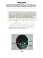
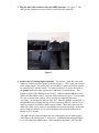
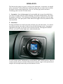
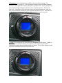
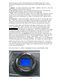
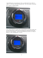
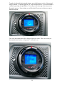
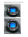
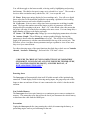
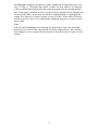
FOR CAN VW/Audi VEHICLES by USER MANUAL FIRMWARE VERSION 6.0 www.aeroforcetech.com Made in the USA! Patent Pending WARNING Vehicle operator should focus primary attention to the road while using the Interceptor. The information provided by this device should be observed as part of a normal sequence of observations performed in the operation of the vehicle, as with any gauge or other instrumentation. Interceptor settings should be changed only during conditions when it is safe to do so. Focusing on the road should be the primary concern of the driver. Aeroforce Technology Inc. shall not be held liable in any way for any incidental or consequential damages to the vehicle, driver, passengers, and or other involved parties or property occurring while using the Interceptor scan gauge. Aeroforce Technology Inc. shall not be liable for technical or editorial errors or omissions made herein, nor for incidental or consequential damages resulting from the furnishing or use of this manual. Aeroforce Technology Inc. reserves the right to make changes to this document and the product described without notice. Copyright 2005-2015 Aeroforce Technology, Inc. All rights reserved. 2 INSTALLATION Read these instructions thoroughly before installation. Also, be sure to check for your vehicle specific notes in appendix A at the end of this manual. There could be important information there concerning your gauge and its installation. New parameters are added from time to time, and may not be listed in this manual. For the latest updated manual go to www.aeroforcetech.com/usermanual.html and select the latest release that pertains to your gauge. 1. Configure gauge bezel and face if desired. Unscrew bezel and lift off the lens and face. Once the face and lens is off, do not touch the LCD display. It will scratch very easily. The lens has a scratch resistant coating on the surface. In the retail box you will find an additional white face. Optional black, polished silver, and brushed silver bezel along with various other face options can be purchased separately from the accessories page. Re-assemble the gauge using any combination of face and bezel desired. When screwing on the bezel, do this carefully as to not cross thread it. If threaded properly it should turn about 2 to 2 ½ times before being tight. 2. Make sure the car’s ignition is turned off. 3. Run included 5’ main cable, and three wire mini cable, from the OBD2 connector (do not plug in yet) to the location of the Interceptor(s). The Interceptor will fit in any 2 1/16” or 52mm gauge pod, or can be mounted in a custom fashion anywhere within 5 feet of the OBD2 connector. The OBD2 connector is located under the dash on either side of the steering column. 9.5’ cables are available from our accessories page if extra length is needed. 4. Plug both cables into the back of the Interceptor. See figure 1. Press the Interceptor(s) into the gauge pod or mounting hardware. Figure 1 3 5. Plug the main cable connector into the OBD2 connector. See figure 2. The data, ground, and power on most vehicles come from this connector. Figure 2 6. Connect the 0-5v analog inputs (optional). You will see 3 pins above the main connector on the back of the gauge as shown in figure 1. The 2 outer pins connect to the analog inputs. The center pin is for switched 12v power and is not required for virtually any CAN bus vehicle. To connect switched 12v power first remove the jumper next to the main connector if connecting to external power. This jumper is required for OBD2 port power only. Connect separate red power wire, which exits the middle of the 3 wire mini cable as shown in figure 1, to a switched 12v line or circuit in the vehicle. These circuits are commonly known as “accessory” circuits because they are only “hot” when the ignition is turned on. A recommended way of doing this step is to use a product called an “Add a Circuit”, made by Littelfuse, available at most car parts outlets. These kits, which sell for under $10, allow you to easily use an existing circuit in the fuse block, such as the power windows, sunroof, etc. to power the gauge only when the ignition is on, known as ACC circuits. The right side pin, when looking at the rear of the gauge, goes to analog input 1. The left pin is for analog input 2. See figure 1. Included in the gauge packaging is a 3 wire cable that connects here. Once attached to the gauge, you’ll see that 4 the green wire is for analog 1, the white for analog 2. These inputs can be used to read the outputs from pressure senders, A/F ratio analog outputs, 2 or 3 bar MAP sensors, or any voltage up to 5v that you want to monitor and/or record. You can scale these signals with a menu function described below. These inputs are rated for 0-5 volts, with an over-voltage protection circuit built in. However, running more than 6v into these inputs for an extended period of time could effect the operation of the entire gauge, and possible damage it. 7. Connect switched 12v power (if necessary). The center pin of the 3 wire harness is for switched 12v power and is not required for virtually any CAN bus vehicle. However, if the gauge is not turning on/off as desired with power coming from the OBD2 port, you can use this method of power as an alternative. To connect switched 12v power first remove the jumper next to the main connector if connecting to external power. This jumper is required for OBD2 port power only. Connect separate red power wire, which exits the middle of the 3 wire mini cable as shown in figure 1, to a switched 12v line or circuit in the vehicle. These circuits are commonly known as “accessory” circuits because they are only “hot” when the ignition is turned on. A recommended way of doing this step is to use a product called an “Add a Circuit”, made by Littelfuse, available at most car parts outlets. These kits, which sell for under $10, allow you to easily use an existing circuit in the fuse block, such as the power windows, sunroof, etc. to power the gauge only when the ignition is on, known as ACC circuits. 8. Turn vehicle on. With the key on and engine off, or engine running, the Interceptor will power up. While the unit powers up, the “Interceptor” or other user selected power-up screen on the display momentarily. This only takes a few seconds. When turned on for the first time the Interceptor will ask you to enter a list of parameters that will then be available for scan, see “Setup” below in the Operation section for more details on this. See page A1 of these instructions for the list of parameters supported by the Interceptor. Remember that not all parameters are supported by every vehicle, so don’t expect to be able to view them all on the Interceptor you install in your vehicle. If the vehicle and the Interceptor support the parameter, you will have access to it. 5 OPERATION The first time the gauge sees power it will go to the main menu. At this time you should select “parameters” as described below and choose those that you wish to have available. For better visuals on these items below visit our YouTube page (search Aeroforce Technology) and view the VW/Audi videos. 1. Scan mode: Once the Interceptor has been installed and set up as described below, you will see an upper and lower field containing a description and parameter value when the ignition is turned on. The left button will change the upper parameter field, the right button the lower. One quick push of either button will toggle to the next parameter in the associated field. 2. Main Menu Pressing both buttons in normal scan mode will take you to the main menu. You will see one selection at time, the order of which is listed in the following section. Pressing the right button will toggle you down to the next menu selection. Pressing the left button will take you back to normal scan mode, which looks like this: To select a menu option, momentarily press both buttons while on that selection. Once in a menu selection, if you are asked to choose between options, toggle to the option desired using the left and right button and press both buttons to select. 6 1. Parameters: Lists all parameters available to be accessed by the gauge. See Appendix 1 and 2 on pages 18, 19 for list and descriptions of each available parameter. Scroll down through the list with the right button, up with the left. Select a parameter by momentarily hitting both buttons while the cursor is on that parameter. Deselect the same way. A small box will be placed in front of each selected parameter. Once you have selected all desired parameters press and hold both buttons to save. Hold until you see the message “closing menu” and you will be returned to normal scan mode. 2. Cyclic: By selecting this, all items selected in Parameters will be shown. Cyclic, or better known as cyclic scan, allows you to choose up to 8 parameters that will be automatically toggled through without hitting any buttons. They will be displayed on the upper/lower field format used in normal scan mode. 7 As before use right button to toggle down, left up. Select a parameter by momentarily pressing both buttons while on the desired parameter. You do not have to select 8 parameters, choose however many up to 8 that you wish to see. When finished press and hold both buttons until you get to the next sub screen which will ask “Enter Cyclic Mode?” Select “yes” or “no”. If no is selected you will return to the main menu. If yes, you will then be asked “Bottom only?” By choosing “yes” you will be choosing cyclic scan on the bottom field only, with the top field constantly showing the last parameter displayed on top in normal scan mode. For example, you left scan mode displaying RPM on top, and Coolant temp on the bottom. In this form of Cyclic scan you will see RPM on the top only, and the other parameters selected will toggle through one at a time in the bottom field. By choosing “No”, you will be choosing cyclic scan in both the upper and lower field. The 1,3,5,7 selections will be shown sequentially on top, the 2,4,6,8 on the bottom. You will then be prompted with the question “Order Chosen?” Selecting “yes” will result in the parameters being displayed in the exact order you selected them. Selecting “no” will result in them being displayed from top to bottom on the list. Finally you will be asked “rate 20?” Selecting yes will result in the screen changing parameters after 20 scans, selecting “no” will allow you to enter a different number of scans. For example, selecting 50 will cause each screen to stay on much longer (50 scans total) before automatically changing to the next set of parameters. After this selection you will go to cyclic mode and begin to see data. To exit Cyclic Scan, press either button and the gauge will stop cycling and go back to normal scan mode. Use Cyclic Rate, found down the menu list (#14) to enter the delay time between display switches. Note: You can see all of the parameters selected in Cyclic Scan at the same time in Multi-Screen mode described in the next section. 8 3. Graph: By selecting (pressing both buttons at the same time) you will enter a display showing the last 2 parameters shown in normal scan mode on a live scrolling plot. The data will displayed graphically as well as digitally in the upper left and right corners. The top left data, plotted with a line filled in solid below it, will be the parameter last displayed on the top field. It will correspond to the left axis. The top right data, plotted with a simple line, will be from the bottom field of scan mode. It will correspond to the right axis. The axis for most parameters will “grow” and re-scale as the data value increase. The last largest value will become the top of the axis. There are some exceptions that have stored axis values such as most temperatures, rpm, and boost. Once in Graph mode, you can return to normal scan by pressing the left button. Or, press the right button to go to another screen called Multi-screen mode. In this mode you will see all of the parameters selected in Cyclic scan at one time. Press the right button again to return to Graph mode, or left button to go back to normal scan mode. 4. Record/record play: Select this and you will go to what looks like normal scan mode, except you will see an “R” in the top right corner. Once throttle % exceeds 50% (on the TDI models record is triggered when RPM exceeds 1200) the screen colors will invert, and the gauge will start recording the 2 parameters displayed. This will last about 90 seconds. When complete the gauge warning lights will flash and the gauge will invert again and return to normal scan mode. If menu is entered again, you will see Record Play where Record was. If you choose this you will have the option to view the data or do another record, which erases the last one. If you choose to play the file, you will see a screen identical to normal scan mode only with static numbers. Pressing the right or left 9 button one press at a time will step through each recorded data point one at a time. Pressing and holding the button will automatically scroll through the data at real time speed. 5. Dimmer: Use right or left button to select “High”, “Medium”, and “Low”. Press and hold both buttons to exit back into scan mode. 6. Invert Screen: Select to swap foreground and backround colors. Note that color backround with dark (black) numbers is easiest to see in bright light. 7. DTC: Select to read and clear trouble codes (check engine light). When first selected it will ask if you want to proceed and reboot. If yes you will see gauge initialize and display codes or tell you that none were found. It will then ask if you want the code(s) cleared. 8. Performance: This selection initiates a timer for 0-60, 60-130, 1/8 mile, and ¼ mile times. Make sure vehicle is at a standstill. Select this option by pressing both buttons. The gauge will indicate that timing will begin when the vehicle starts moving. Once moving the screen inverts colors and you will see the two parameters last viewed in normal scan mode, with a small indication of distance travelled in the corner. When you’ve travelled a full ¼ mile a summary screen will come up showing your results. 9. Annunciator: This allows you to select one or two parameters to monitor in the backround and enter a threshold to be compared too. If the entered threshold is exceeded the annunciator lights will light up. Until the parameter’s value goes below (or above if selected) the threshold. The first thing you will see in this selection is a list of all parameters that you chose in parameters (the first menu selection). Toggle down and select one or two by placing cursor next to it and pressing both buttons. Once done press both buttons and hold until you see message “menu closing”. If you’ve selected 2 parameters you will be then asked “And Function?” If you choose “yes”, the annunciator will light if both parameters exceed their thresholds. For example, you want the lights to indicate that A/F ratio is above 12.0 AND throttle position is above 75%. If you select “No”, the lights will come on if either parameter exceeds its threshold. For example, you want to know if knock goes above 3 degrees or if coolant temp exceeds 220 deg F. The next screen will look like this: First select “Above” or “Below” depending on when you want the lights to light. 10 Press both buttons to accept and proceed. Now you will be asked to enter “Plus” of “Minus” as a first step in entering the threshold value. This is how gauge will determine if it is a positive or negative number. Next, enter the number by toggling right or left through the list of numbers starting with the most significant digit. Once you’re on the number press both buttons, then repeat until you’ve entered all digits. At the end of the number list you will see a “P” and “X”. Select “P” to enter a decimal point, “X” to save. 11 Finally it will ask for a rate, default being 1. This rate represents how many scans of displayed data before the annunciator will look at the monitored parameter(s). “1” is the fastest rate you can select. “4” would allow both parameters to update twice for each time the annunciator looks at its parameter. Slower changing parameters like temperatures can be monitored less often allowing the normal scan mode to update faster. Make your selection by highlighting it and then pressing both buttons at the same time. After this step you will be taken back to normal Scan mode. The Annunciator will be active at this point. To turn it off go back in the main menu, toggle to “Annunciator Off” (this replaces the original selection titled “Annunciator”) and select. This will now go back to saying “Annunciator”. Note: The annunciator function reacts very fast, and can be used as a shift light if desired. It actually reacts faster than the stock tachometer as a point of reference. It is recommended that only one parameter (RPM) is chosen for annunciation if this is the purpose, as update rate slows as more things are monitored by the gauge. If high speed is required for these warning lights, such as for a shift light, you will want to only select one parameter. Adding a second to be monitored by the warning lights will slow down the data acquisition. 11. Analogs: Allows you to enter conversions and names for both analog inputs. When you select this by pressing both buttons you will be asked to enter the slope for analog 1. If you are editing a previously setup input you will be asked if you want to edit it. You will then be asked to enter the two conversion coefficients that convert the voltage input to engineering units such as psi, deg f, etc. If you are using a temp sensor these values are irrelevant because once you select “Fluid temp” or “Air Temp” a special conversion will automatically be entered as described below. For all other sensors you then select whether the first number is positive or negative as shown below: 12 Using the buttons, toggle to the appropriate sign, then press both buttons to enter. You’ll then go to the next screen and be asked to enter the value: 13 Toggle to the desired digit using the buttons, press both buttons to select. Repeat until slope is entered. To finish, toggle the “X” at the end and select it. You will be asked to confirm by pressing the right button. You will go to the intercept value entry screen. Repeat the process. Upon exiting, you will be asked if you want to choose or enter a name description: If you want it named “Analog 1” select no. This is the description that will be displayed above the value. There are several predetermined names such as “oil pressure”, “A/F ratio”, etc.: 14 Toggle to the desired name and press both button. If you are using a temp sensor, select Fluid Temp or Air Temp, then select “no” if asked if you want a custom label. To enter a custom label choose “Air Temp/Custom”. You will then see this screen: Highlight “OK” and you will be taken to this screen: 15 You will then toggle to the letters needed, selecting each by highlighting and pressing both buttons. The third to last spot is empty an is selected for a “space”. The second to last is to delete a mistaken entry, and the last, “Ok”, is to accept and exit. 13. Boost: Brings up a unique display for boost readings only. You will see a digital boost value above a horizontal bar graph also representing a qualitative boost reading. Press either button to exit back to normal scan mode. 14. Cyclic rate: Select to enter a delay time between parameters switching in cyclic scan. The larger the number entered the longer each set of parameters will remain displayed before switching to the next. “Rate = 20” is the default value, this means that the gauge will make 20 scans before switching to the next screen. You can change this, a higher number will keep each display up longer. 15. Status: VW TDI engine only: Brings up a screen displaying annunciator selections 16. Annunc. Graph: This will bring up a unique graphical display showing the parameter(s) chosen when the annunciator was set up. This will be a live scrolling graph of the parameter(s) with the entered threshold as the top of the vertical axis. This will allow you to view these chosen parameters and get a qualitative view of how near they are to your entered limits. For videos showing many of the setup functions described above check out our Youtube channel, “Aeroforce Technology”, and search for “VW/Audi” videos. !!!BE SURE TO CHECK OUT OUR COMPLETE LINE OF COMPATIBLE SENSOR KITS, INCLUDING OIL AND FUEL PRESSURE, TEMPERATURE, EGT, MANIFOLD PRESSURE (BOOST), AND WIDE BAND O2, AT WWW.AEROFORCETECH.COM!!! Powering down The Interceptor will automatically shut itself off within seconds of the ignition being turned off. If both display fields are showing analog inputs, the gauge may take a little longer to time out and turn off since it is not connected to the vehicle’s data bus in this situation. Non-Volatile Memory The Interceptor does not require batteries or a continuous power source to maintain its memory. This means that your data will not be lost if you disconnect the vehicle battery or disconnect the cable from the OBD2 port. Precautions Unplug the Interceptor before jump starting the vehicle, disconnecting the battery, or performing engine work to prevent damage to the unit. 16 The Interceptor’s display is designed to operate continuously at temperatures up to 150 deg. F (70 deg. C). The display may appear “washed” out for a minute or so if exposed to direct sunlight in hot climates after the car has been parked for an extended period of time. If the gauge is mounted in such a way that it can be exposed to direct sunlight, such as on top of the dash, you may want to consider a windshield shade, or unplugging the display for a minute or two until it and the car cool off a little. If the vehicle will not be used for more than 5 days it is recommended to unplug the gauge(s) to prevent excessive battery drain. Care If the face of the Interceptor needs cleaning, use light pressure with a non-scratching material such as a micro-fiber material made for plastic sunglass lenses. If the face has been changed, be sure to replace the lens properly as described in step 1 of page 3 of this manual. 17 Limited Warranty Aeroforce Technology warrants this product and its accessories against defects in material and workmanship for a period of 1 year from the date of purchase. Aeroforce Technology will repair or replace this product with new or refurbished products or parts, at Aeroforce’s option, free of charge in the USA. This warranty extends only to the original purchaser. A purchase receipt or other proof of date of original purchase from and authorized dealer (including Aeroforce Technology) is required on order to have warranty service performed. Before sending an Interceptor back for warranty service, you must obtain a Return Materials Authorization number from Aeroforce Technology. This can be done by emailing [email protected] including a description of the problem and date/place of purchase. An RMA number will be returned to you as well as a return address. This warranty covers failures due to material or workmanship defects only. This warranty does not cover cosmetic damage or damage due to accident, misuse, abuse, negligence, commercial use, acts of God, or modifications of, or any part of the product, including accessories. 18 A1 VW/Audi Gasoline Engine Parameters 1. RPM 2. COOLANT TEMP DEG T (C) 3. MPH 4. ENGINE LOAD 5. MASS AIR G/S 6. INJ TIMING MSEC 7. INTAKE AIR TEMP DEG F (C) 8. THROTTLE ANGLE 9. IGNITION TIMING ANGLE – ignition advance 11. MISFIRE CYL. 1 12. MISFIRE CYL. 2 13. MISFIRE CYL. 3 14. MISFIRE CYL. 4 15. KNOCK RETARD 1 16. KNOCK RETARD 2 17. KNOCK RETARD 3 18. KNOCK RETARD 4 19. ALTERNATOR LOAD 20. VOLTAGE SUPPLY V 21. FUEL SUPPLY PRESSURE (MPa) 22. FUEL RAIL PRESSURE (MPa) 23. BAROMETER 24. WASTEGATE N75 VALVE 25. BOOST SPECIFIED 26. BOOST ACTUAL 27. LAMBDA 28. A/F RATIO 29. TORQUE TO TRANSMISSION 30. CLUTCH PRESSURE 1 31. CLUTCH PRESSURE 2 32. TRANSMISSION FLUID TEMPERATURE- deg f 33. CLUTCH OIL TEMPERATURE – deg f 34. ANALOG INPUT 1 35. ANALOG INPUT 2 19 A2 VW/Audi TDI Engine Parameters 1. RPM 2. COOLANT TEMP DEG T (C) 3. Hi FUEL PRES PSI – fuel pressure at the rail 4. MPH 5. FUEL TEMP 6. INTAKE AIR – Intake air temp 7. TORQUE LIMIT 8. TRANS TORQ LIMIT 9. MASS AIR FLOW – lbs/min or grams/sec 10. BAROMETER 11. BOOST SPEC – boost level commanded by ECM 12. BOOST ACTUAL 13. VOLTS 14. TORQUE ACTUAL 15. FUEL CONS. – calculated fuel consumption (unverified) 16. HI FUEL PRS SPC – hi fuel pressure level specified by ECM 17. IGN TIMING – ignition timing 18. DIFF PRESSURE – differential pressure across the particulate filter 19. CAT PRE TURBO TEMP – EGR temp before the turbo 20. CAT PRE FILTER TEMP – EGR temp before the particulate filter 21. CAT AFT FILTER TEMP – EGR temp after the DPF 22. ANALOG INPUT 1 23. ANALOG INPUT 2 20 A3-TIPS AND VEHICLE SPECIFIC NOTES When displaying or monitoring (such as with the annunciator) a mixture of engine and transmission parameters expect the update rate to slow considerably. The gauge must initialize each controller before asking for data when switching between them. For fastest update rate only display all engine or all transmission parameters. Visit our Youtube channel,"Aeroforce Technology", for video instructions on most of the features and set up procedures for the VW/Audi gauge. To make the annunciator respond as fast as possible, for example using it to monitor RPM as a shift light, select the parameter being monitored to also be viewed. This will result in the annunciator lights reacting with no delay vs perhaps 100-200 msec if two separate parameters are being displayed and another being monitored. 21