1
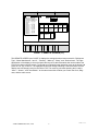
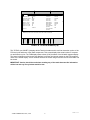
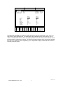
FCB MODEM SOFTWARE USER MANUAL P/N 2274 (Version 4) IMI CORNELIUS INC; 1995 1 Printed in U.S.A. Barrels * and * CONNECT SCREEN ** : ** ** FCBCOMM STATUS Barrels 1 and 2 Connection No response Barrels 3 and 4 No response Software External devices ****** ****** ************ ************ F 10 to establish communications ; ctrl–F10 to stop communications FCBCOMM SETUP Serial Port Selection: Modem Selection: Phone No. For Modem: Printer Output : COM 1 No Modem FCB.DAT Press SPACEBAR to change the selection. <ESC> to EXIT F –Connect F 1 & Exit 2 –Stat & Dipsw F –Remote Control 3 F –Totals F –Monitor F 4 5 8 –Print Communications is OFF CHART 1. CONNECT SCREEN (F1) CONNECT SCREEN This CONNECT SCREEN (see CHART 1) is displayed when the FCB software is started using DOS prompt A:FCB and pressing ENTER or RETURN key on the key board. SERIAL PORT SELECTION To start communication to an FCB Unit, the correct “Serial Port selection” must first be selected. This port would be the address (“COM 1”, “COM 2”, “COM 3”, or “COM 4”) that the phone modem installed in your PC is using. To change the port selection, move the Com field using the “UP”, “DOWN”, “LEFT” or “RIGHT” arrow keys on the PC keyboard, then by pressing the “SPACE BAR” the field will roll to the proper selection. To select the field, press the “ENTER” or “RETURN” key. Note: This procedure for entering information and moving to a selected field is used for all the FCB screens. MODEM SELECTIONS This field is used 3 ways to communicate to an FCB Unit. The No Modem is used when connecting directly to an FCB Unit and no telephone connections/modems are used when troubleshooting at the store. This would require a direct cable connection between the FCB and a serial port. The DCE/DTE switch located on the Modem Interface board must be in the DTE position or a Null Modem Adapter must be used. The manual dial mode can be used using the telephone to dial, then start communication (F10), then press any key after the carrier signal from the FCB modem is heard, then hang up the telephone receiver. The Auto Dial mode is used when the appropriate number is entered in the “Phone Number For Modem” field. PHONE NUMBER FOR MODEM In this field, enter the telephone number of the store that you wish to communicate with. Remember to include any prefix that may be required for an outside line e.g. 916124216120 where 9 would be for an outside line,1 for long distance, 612 for the area code, then 4216120 for the telephone number. DO NOT use any spaces when entering your number. In some instances, a pause may be required to attain a dial tone by using a , (comma). Each comma will cause a 2 second pause between numbers e.g. 9,1,6124216120. IMI CORNELIUS INC; 1995 2 Printed in U.S.A. CONNECT SCREEN Barrels 1 and 2 (Ctrl–T) 11:15 AM FCBCOMM STATUS Barrels 1 and 2 Connection ACTIVE Software V3L93AA External devices None Barrels 3 and 4 ACTIVE V3L93AA None F 10 to establish communications ; ctrl–F10 to stop communications FCBCOMM SETUP Serial Port Selection: Modem Selection: Phone No. For Modem: Printer Output : COM 2 Autodial Modem 3141 FCB.DAT Press SPACEBAR to change the selection. <ESC> to EXIT F –Connect F 1 & Exit 2 –Stat & Dipsw F –Remote Control 3 F –Totals F –Monitor F 4 5 8 –Print CHART 1A. CONNECT SCREEN (F1) PRINTER OUTPUT This field is used with the Print Screen function. All the data displayed on any of the screens can either be stored to a file on your PC or be directly printed out to a printer. To print a screen, enter the port LPT1, 2 etc., that your PC uses. To store a screen, enter the file name you wish to store it on e.g. A:FCB.DAT. This would record the data to A drive FCB.DAT file or C:store123.dat could be used to store screen to the C drive with a file set up to store data on a given store. Note: The file length can be a maximum of eight characters with a three character extension (normal MSDOS file). ESTABLISHING COMMUNICATION To start communication with an FCB Unit, press the F10 key. If all modem set fields and phone connection are correct, the screen will change status from No Response to ACTIVE as shown in CHART 1A. During the connection, the lower right–hand display on the screen will display “initializing modem connection”, then Dialing the modem– – –, then blank. If power to the FCB is not on, or improper cable or the DTE/DCE switch on the Modem Interface board is not in the DCE position, the lower right–hand display will display “Looking for barrels 1 and 2”, then “Looking for barrels 3 and 4”. The system will then automatically re–dial and try again. If this continues, press the “Esc” key on the PC keyboard and correct the set–up at the FCB end. The software field will display the revision of the software installed in the FCB. The “ External devices” will display any Personality Modules that may be connected to the FCB Unit. Note: These modules are connected to the Modem Interface board as mentioned in the installation instructions for the Modem Interface Module. The top line of the PC screen displays the “Barrels 1 and 2 (Ctrl-T)”. If connected to a Four– Flavor FCB Unit, pressing the PC keyboard control (ctrl) & “T” keys simultaneously will switch from “Barrels 1 and 2 (Ctrl–T)” to “Barrels 3 and 4 (Ctr-T)”. The top line also displays the time of day readout from the clock inside the FCB Unit. The remaining PC screens (F2 through F5) shows typical information displayed. IMI CORNELIUS INC; 1995 3 Printed in U.S.A. Barrels 3 and 4 (Ctrl–T) 2:56 Pm DIPSWITCH SCREEN Dipswitches : Barrels 1 and 2 ON Switch OFF Switch OFF Switch OFF Switch OFF Switch 1 2 3 4 5 ON Switch 6 (Unused) ON Switch 7 (Unused) OFF Switch 8 (Unused) ON Switch 9 Hot Gas OFF Switch 10 Timer Reset POS Message POS Message Mechanical Exp. Valve Motor Calibration Disable Calibration < Settings differant from physical dipswitches are marked by “ "” > Calibration Mode: Beater: Calibration: Barrel 3 148 18 Barrel 4 153 21 Arrow keys move cursor; space bar selects ON or OFF. F –Connect F 1 & Exit 2 –Stat & Dipsw F –Remote Control 3 F –Totals F –Monitor F 5 4 8 –Print CHART 2. DIPSWITCH SCREEN (F2) This CONNECT SCREEN (see CHART 2) displays the 10 DIP switch settings that are located on the FCB master circuit board ( Four–Flavor FCB has 2 master circuit boards ).To emulate a switch change, use the cursor to move the highlighted box to the switch you desire to change, then press the spacebar. The program will display “type Yes to confirm” after the spacebar is pressed. When a switch setting has been changed, the switch will be designated by the " symbol as listed on the screen. After communication is disabled to the FCB, the FCB will default to the actual physical settings on the Unit. CALIBRATION MODE The calibration mode is used to calibrate the beater motors as you would by turning the adjustment potentiometers located on the relay boards.This mode is activated when DIP switch 4 is set to the “ON” position. The software will remind you to assure that the barrels are fully defrosted before you enter this calibration routine. After defrosting the FCB ( REMOTE Screen “defrost” ) a value may be entered into the calibration field for each barrel. Note: To fully defrost the FCB, it is recommended to manual defrost the Unit at least 5 times. The numbers used for calibration range from 1 to 40 with 20 as the midpoint or zero offset. An example would be if after fully defrosting in normal calibration of an FCB, you might see the calibration beater screen Barrel 3 read 148 and Barrel 4 read153; this would indicate that the Unit needs a plus 2 correction to side 3 and a minus 3 to side 4. This would be entered into the calibration as 22 and 17. The Beater display after entering the calibration will update to 150 and the calibration will be complete. IMI CORNELIUS INC; 1995 4 Printed in U.S.A. Setup Info Front Panel Ref–Type, R404A2HP Motor Mfg 1 EMERSN 60 Motor Mfg 2 EMERSN 60 Visc set 08<<>>07 Wake up ––––––– ––––––– Sleep Defrost Defrost Defrost Defrost Defrost Defrost Defrost Defrost Defrost 1 2 3 4 5 6 7 8 9 11:15 AM REMOTE SCREEN Barrels 1 and 2 (Ctrl–T) 12:00 AM 4:00 AM 6:00 AM 10:00 AM 2:00 PM ––––––– 7:00 PM 9:00 PM ––––––– Display: SYRUP 2 Auto 1 Wash 1 Auto Blend 1 Fill 1 Hidden Switch Error Reset Auto 2 Wash 2 Auto Blend 2 Fill 1 Off 1 Off 2 Defrost (select) Cancel Def (Advance) Menu ************************ ARROW and CURSOR keys, move cursor; < ALT > key simulates a button press. F –Connect F 1 & Exit 2 –Stat & Dipsw F –Remote Control 3 F –Totals F –Monitor F 4 5 8 –Print CHART 3. REMOTE SCREEN (F3) This REMOTE SCREEN (see CHART 3) displays the settings that have been entered for “Refrigerant Type”, “Motor Manufacturer 1 and 2”, “ Viscosity”, “Wake up”, “Sleep”, and “ Defrost times”. The right– hand portion of the display is the control panel and any touch switch actuation that can be made at the FCB can be done using this screen. To simulate a touch switch panel operation cursor to the button and press the “Alt” key on the PC. The highlighted button will change indicating a switch activation and the display area will change just as it would at the FCB. The menu key simulates pressing the 3 buttons “Auto 1”, “Wash 1”, and “Auto Blend 1” at the same time which will allow you to enter the Clock, Diagnose, and the other menus. IMI CORNELIUS INC; 1995 5 Printed in U.S.A. Barrels 1 and 2 (Ctrl–T) 11:15 PM TOTALS SCREEN TOTALS Compressor run 2441:25 Auto side 1 10844:09 Compressor cycles Defrost 1 cycles Defrost 2 cycles 25010 2980 2929 Auto side 2 Error side 1 10818:09 0:00 Blender 1 cycles Blender 2 cycles Syrup out 1 cycles 3300 5100 24 Error side 2 Beater Motor 1 Beater Motor 2 Sleep Mode 10848:09 10830:09 0:00 Syrup out 2 cycles 99 Power on 11868:10 Syrup Solenoid 1 (minutes) Syrup Solenoid 2 (minutes) 0:00 304 353 ARROW keys move cursor; F10 clears cursor value; CTRL–F10 clears all. F –Connect F & Exit 2 1 –Stat & Dipsw F –Remote Control 3 F –Totals F –Monitor F 4 5 8 –Print CHART 4. TOTALS SCREEN (F4) This TOTALS (see CHART 4) displays all the Totals information and is useful to determine up time of the FCB and cycle and hours of the listed components. This screen displays the actual number of compressor and blender cycles. The FCB displays these values (X100) because of the limited 8-segment display. The hours information on this screen also displays in minutes and are not present on the FCB; again because of the limited display. These numbers can also be zeroed using this screen and all of the totals can be zeroed. IMPORTANT: Caution should be used when resetting any of the totals because this information will be lost and any life cycle data would be lost. IMI CORNELIUS INC; 1995 6 Printed in U.S.A. Barrels 1 and 2 (Ctrl–T) MONITOR SCREEN 11:15 AM Machine status Compressor state: Compressor run time: Compressor cycles: Inlet temp: Syrup: Water: Beater: Defrost: Refrigeration: Pulse time: Viscosity: Calibration: F –Connect F & Exit 2 1 –Stat & Dipsw Carbonator: Line voltage: Outlet temp: OFF 25 min. 10 cyc F –Remote Control 3 Barrel : 1 Barrel : 2 86_F OFF OFF ON OFF OFF 1130 MSEC 10 21 83_F OFF OFF ON OFF OFF 0 MSEC 10 20 F –Totals F –Monitor F 4 5 8 ON 220 volts. 83_F –Print CHART 5. MONITOR SCREEN (F5) The MONITOR SCREEN (see CHART 5) shows the status of the FCB components “ON”, “OFF”, etc; and can be a useful diagnostic tool. The Carbonator status indicates that the control relay is “ON” or “OFF”. If the Carbonator status is “ON”, it is indicating that the CO2 and water pressure switches are satisfied allowing the carbonator to function. The Pulse time display indicates the on time that the refrigeration valve is on. When the FCB is refrigerating , the “ Refrigeration” display will alternate“ON” and “OFF” indicating its pulsing action. IMI CORNELIUS INC; 1995 7 Printed in U.S.A.


![Fountain Program [ 001930 ]](http://vs1.manualzilla.com/store/data/006022682_1-35065e157ee046f990de9548b34d6090-150x150.png)