1
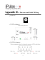
Universal iPulse® Ethernet Adapter User Manual January 2011 Table of Contents Introduction 3 Overview 4 Package Checklist 4 Product Features 4 Product Specifications 6 IPulse-e Description & Installation 7 Product Panel Views 7 Top Side 7 Right Side 7 Left Side 8 LED Indicators 9 Wiring Architecture 10 RS-232 Wiring Architecture 10 RS-422/RS-485 Wiring Architecture 10 iPulse-e Configuration 12 Initial IP Configuration 12 Device Management Utility 12 Web Browser Configuration 16 Login Setting 16 Login Setting Page Field Description 17 Parameter Setting Page 17 Controller Updated 23 Factory Default Setting 24 Setting Verification 25 HyperTerminal for TCP/IP WinSock 26 Data Transmission 26 Appendix A- FAQ 27 Appendix B - Pin-outs and Cable Wiring 28 □□DC-In Jack □□RJ-45 Pin Assignment 28 □□RS-232 Pin Assignment □□RS-232 Wiring Diagram 28 □□RS-422 Pin Assignment 29 28 29 1 □□RS-422 Wiring Diagram □□RS-485 Wiring Diagram 29 29 Appendix C - Troubleshooting Guide 30 Appendix D - Firmware Upgrade 31 2 1 Introduction The iPulse-e is a virtual Ethernet i/o device that works in conjunction with iPulse® standard and iPulse-PoE devices to provide intelligent device reboot (iDr®) for client devices that may not have an available alarm out or GPIO port. In addition to its base functionality, the iPulse-e can be used to provide new ways of connecting and communicating with legacy serial devices on a Local Area Network (LAN) or Wide Area Network (WAN). Its TCP/IP channel is designed to operate serial ports over 10/100 Ethernet networks transparently to its native functionality as virtual I/O device. To do this, data is transmitted via TCP/IP protocol and converted to serial packets. This provides a control mechanism to standard and industrial serial devices via Ethernet, Intranet and Internet. The iPulse-e is packaged in a PVC material case and designed for industrial environments. There are two supported serial ports: an RS-232 port and an auto detecting RS-232/RS-422/RS-485. All serial ports operate in the common industrial configurations. The following topics are covered in this chapter: Overview Block Diagram Product Features Product Specifications 3 Overview The iPulse-e is designed to make your iPulse® support intelligent device reboot on client devices that do not have their own alarm output or GPIOs. Additionally it can serve as serial device server (SDS) or industrial serial device interface and provide instant network/internet access to serial devices. With a high performance CPU the iPulse makes an ideal choice for connecting RS-232, RS-422 or RS-485 serial devices—such as PLCs, smart meters, and sensors—to an IP-based Ethernet LAN, making it possible for your software to access serial devices anywhere and anytime over a local LAN, WAN or the Internet. To ensure network compatibility the iPulse-e uses standard network APIs (Winsock or BSD Sockets) and supports TCP Server, TCP Client, and UDP Modes. You will have your iPulse-e software running over the COM port via your TCP/IP network in no time. This feature preserves your software investment and lets you enjoy the benefit of networking serial devices. The web browser interface supports the following protocols: TCP, IP, UDP, HTTP, DHCP, TELNET, and ARP. Package Checklist The iPulse-e ships with the following items: iPulse-e universal TCP/IP converter and virtual i/o Driver Virtual i/o to iPulse® interface cable (optional serial tap if SDS usage desired) Power transformer (9-12VDC, 500mA) Documentation (software downloadable from www.videogenix.com) Quick Setup Guide Product Features Data Conversion between RS-232 and RS-422/485 and Ethernet 1-RS-232 port, 1-RS-422/485 port: receives data/signal into the TCP/IP package data/signal and sends them out as Ethernet data; or transmits TCP/IP package data/signal into serial device data/signal. Socket Communication iPulse-e provides the standard single socket connection.. Dynamic IP Configuration iPulse-e supports DHCP client mode, to simplify network address configuration. 4 Dual LAN Speed iPulse-e supports 10/100 Mbps Ethernet (auto-detected) Server / Client Dual Modes iPulse-e devices can be configured as network servers or clients. In the client mode, it can be installed in a network which is protected by NAT router or firewall, without the need of a real static IP address. Web-based Setup Device configuration is done through standard browsers via HTTP protocol (IE, Netscape). No special software or operating system specific drivers required. Built-in Security Control Security protection is by login password to prevent intruders. Remote Reprogramming Firmware can be reprogrammed directly to keep up with latest software for your device. 5 Product Specifications Ethernet ● Port Type : RJ-45 Connector ● Speed : 10/100 M bps (Auto Detecting) ● Supported network protocols: ARP, IP, ICMP, UDP, TCP, HTTP, DHCP, TELNET ● Operating modes : TCP Server/TCPIP Client/UDP Client ● Setup : HTTP Browser Setup (IE, Netscape) ● Security : Login Password ● Electrical Protection : Built-in 1.5KV Magnetic Isolation Serial Port ● Ports: 1-RS232 Port, 1-RS-422/485 auto-detecting Port ● Port Type:DB9 male ● Supported Serial Speeds:300 bps〜115.2k bps ● Parity:None , Odd , Even, Mark, Space ● Data Bit:5,6,7,8 ● Stop Bit:1 , 2 ● Port 1: One RS-232 Signals Port:Rx , Tx , GND , RTS , CTS , DTR , DSR , DCD ● Port 2: One RS-422/485 Port (Auto-Detect) RS-422 Signals:Rx+ , Rx- , Tx+ , Tx- (line surge protection) RS-485 Signals : Data+ , Data- (line surge protection) Built-in RS422/RS485 Pull Up/Down Resistor Socket Port Connection:1 Connection 15KV ESD for all signals Built-in Watch Dog Function Virtual Support Windows 2000 /2003 / XP Firmware On-line Updated Via Ethernet Power: 9-12Vdc , 500mA LEDs: PWR (Green) DATA (Red-blinking during data Tx/Rx) LAN Speed Indicator (Red for 10 Mbps; Green 100 Mbps) SYS (Red-Blink) Environment: Operating Temperature:0℃〜70℃ Storage Temperature:-10℃〜85℃ Dimensions:90 * 60 * 20 mm ( W * D * H ) WEIGHT:65 gm RoHS:Compliant with RoHS Regulatory Approvals:FCC Class A, CE Class A WARRANTY:1 year 6 2 IPulse-e Description & Installation Product Panel Views Top Side Serial I/O Port RS-485/RS-422 DC-In Power Jack Ethernet LAN Port Serial I/O Port RS-232 Reset Button LED Indicators Right Side Serial I/O Ports; RS-232 and RS-422/485 The iPulse sensing wires should be connected to the green screw terminal strip. Connect iPulse sensing wires directly to the terminal strip on the Port labeled RS-485/RS-422. The brown wire from the iPulse should get connected to the terminal strip labeled Tx and the black wire should go to ground. On older units that purchased prior to 2011, the black wire should always go to the Tx terminal strip connector, the all white or striped wires should go to the terminal strip labeled GND. If you chose to use the DB9 connector with the iPulse serial tap connector then the red cable from the tap should be connected to the brown wire from the iPulse and the green wire should be connected to the black wire. 7 RS-485/422 RS-232 Left Side Power Supply The iPulse-e device is powered by a single 9-12Vdc, 500mA power supply. Connect the power line to the power jack at the left side of iPulse-e. When power is properly supplied, the red Power LED, “PWR” will be on. DC-In Power Outlet Ethernet LAN Port Reset Button Ethernet LAN Port The connector to your network switch is a standard RJ45 Network adapter. Simply connect it to your network switch or Hub. When the connection is detected, the LAN LED indicator will light. When data traffic occurs on the network, red data LED indicator will blink on both Tx or Rx data. 8 Reset Button If by any chance, you forget the setup password, or the iPulse-e stops working, disconnect power then using a paper clip or similar device push in and hold the Reset button while re-attaching power for 5 seconds. All parameters are now reset to the factory default. LED Indicators PWR (Red): Power Indicator: LED is on when power is detected Tx (Green): Data Tx indicator (When Tx data is sent, this LED will blink) Rx (Red): Data Rx indicator (When Rx data is received this LED will blink) SYS (Green): Device status indicator (Under normal operating conditions this LED will blink once per second) 9 Wiring Architecture RS-232 Wiring Architecture RS-422/RS-485 Wiring Architecture When you finish the steps mentioned above and the LEDs are as described above, the iPulse-e is connected correctly. The Setup Tool “CVBrowser.exe” auto detects the iPulse-e and then can configure the device to your network environment. 10 For advanced parameter setup, after you have established device connection, use a web browser (IE or Netscape) and login to the device then proceed to the advanced parameter settings. 11 3 iPulse-e Configuration Initial IP Configuration When setting up the iPulse-e initially you must configure the IP address. For additional details on network settings, see the Network Settings section in Chapter3, “Web Console Configuration”. The following topics are covered in this chapter: Device Management Utility CVBrowser “View” CVBrowser “Modify IP” CVBrowser “Modify MAC” Device Management Utility The iPulse-e ships with the program “CVBrowser.exe” which is a 32 bit Windows program. CVBrowser is used to discover and setup the iPulse-e. CVBrowser uses UDP to query and configure iPulse-e devices on the network. CVBrowser detects the existence of the installed iPulse-e devices and shows the devices and their status, including device’s IP address; Subnet Mask, MAC address, and Device ID (see Figure 3.1). This tool can only setup one iPulse-e at a time. If there is more than one iPulse-e on the network, disconnect or power them down during detection. CVBrowser has following characteristics (UDP Configuration): Broadcast packets are not limited by subnet. Even if the IP address of the iPulse-e and the computer running CVBrowser are not on the same subnet, CVBrowser 12 will detect the iPulse-e. Broadcast packets do not pass routers. CVBrowser can only be used to monitor devices with computer running CVBrowser in the same network segment of local area network. (Figure 3.1) CVBrowser “View” □□ View -> Refresh Select “View” to refresh the status of existing devices on LAN. Similarly clicking on the Icon encircled in red below will refresh the list (see Figure 3.2). Note: Always run the “Refresh” after any data change. (Figure 3.2) File -> Exit (Alt+F4) Exits from the CVBrowser (see Figure 3.3). (Figure 3.3) 13 CVBrowser “Modify IP” □□ Modify IP -> Dialog Frame To modify the iPulse-e’s IP address click the device on the existing devices list in the CVBrowser. Then press the second Icon “Modify IP” on the function bar and the following dialog form will be shown (see Figure 3.4). (Figure 3.4) Assign an IP Address with the same subnet mask as your computer (avoid any IP conflicts with other network devices). When you press the “Confirm” button, the IP address will be refreshed in 2~3 seconds. (Figure 3.5) After clicking “Confirm” you will be prompted as above to “Input Password”(see Figure 3.5). Just press “Confirm” and the new device’s IP will be changed and 14 saved. (Figure 3.6) CVBrowser “Modify MAC” □□ Modify MAC -> Dialog Frame Select the iPulse-e device on the existing devices list in the CVBrowser table and then the function bar below will be displayed. Press the third icon “Modify MAC” on the function bar and the following dialog form will be shown (see Figure 3.7). (Figure 3.7) □□ Input Password -> Dialog Frame Click the “Confirm” button and the “Input Password” dialog box will pop-up (see Figure 3.8). Press “Confirm” and the new MAC address is saved. (Figure 3.8) 15 Web Browser Configuration The following topics are covered in this chapter: iPulse-e Setup ● Login Setting ● Login Setting Page Field Description ● Parameter Setting ● Parameter Setting Page Field Description Login Setting In addition to basic IP address and subnet mask settings, specific device settings can be set over HTTP with popular browsers (Internet Explorer, Netscape, etc). Setup of the iPulse-e is as easy as surfing the WEB; no special software will be required. In the browser address field of your browser such as IE, enter the IP address of the iPulse-e directly, to enter the “Login Setting” page follow the steps below. o Open your browser. (This chapter uses IE as an example) o In the browser URL field, type the IP address of the iPulse-e directly and press ENTER. (The IP address is what you set using the device management utility CVBrowser.) o Press the fourth icon “Web Browser” on function bar and a “Login Setting” Screen will be shown (see Figure 3.9) to login into the device. Alternatively, if the IP address of the iPulse-e is already known, you can connect to the iPulse-e directly by providing its IP address in the address field of browser. (Figure 3.9) 16 Login Setting Page Field Description □□ System time elapsed The time elapsed since starting this device in [Day Hour : Minute : Second] format. □□ Firmware version IPulse-e firmware is identified by date code. □□ Serial number The device’s serial number. □□ Ethernet MAC Address Each iPulse-e has a unique six (6) digit MAC address. □□ Password This field is the administrator’s password. Factory default is no password (blank). It is not recommended to leave the password field blank. If you cannot login, it means you have to enter in the password. If you do not know the password you can turn off the power and then push in the “Reset” button and hold it while unplugging the device from power and then re-plugging it in for 5 seconds. The password will be cleared (along with all other device settings). The iPulse-e uses the same password protection mechanism commonly used in Windows NT or UNIX. If there are more than “3 consecutive login failures” in password entry, the login function will be disabled for “15 minutes”. During this 15 minutes period, no logins are allowed. This prevents hackers from finding the password by computer generated programs. Parameter Setting Page □□ The Parameter Setting Page Type the correct password in the “Password” field and click the “Confirm” button in the “Login Setting” page, then the “Parameter Setting” page shown below will be displayed (see Figure 3.10). 17 (Figure 3.10) □□ Parameter Setting Page IP Address The IP address of the iPulse-e device, 4 digits separated by '.' (i.e. 192.168.0.23). This address should not conflict with other devices on your network. If DHCP client mode is enabled and there is a DHCP server on the network, this field will be assigned automatically by the DHCP Server. Subnet mask Subnet mask of the device the iPulse-e is connecting to. “255.255.255.0” is typical for smaller networks. If your IP address is normally provided by an ISP or the internal network administrator, you may request the IP address information from them. If DHCP client mode is enabled and there is a DHCP server on the network, this field will be assigned automatically by the DHCP Server. □□ Gateway address 18 Gateway or Router IP address. 'Gateway' is a device which connects local networks to external networks. If you need to communicate with other networks or your device owns a real IP address on the internet, you may use that address. If there is no gateway on the network, leave it as “0.0.0.0”. This is typically the IP address of your router. If DHCP client mode is enabled and there is a DHCP server on the network, this field will be assigned automatically by the DHCP Server. □□ DHCP client If DHCP is enabled, there should be a DHCP server on the network. If DHCP is disabled, [IP address], [Subnet mask], and [Gateway address] must be assigned manually. □ Auto Reset If the iPulse-e has been disconnected or hasn’t seen any network traffic for an extended time period, you can have it automatically reboot itself every 1~99 hours. □ Device ID Report You may “Enable” or “Disable” Device ID Reporting. This option is for providing the device ID and assigned ID number for iPulse-e devices. This ID may be any number in the range of “0~65535”. In TCP mode, whenever enabled, this ID will be transmitted each time a socket connection is made. The following format will be used for reporting device ID(s).. Serial #1 nnnnnA[LF][CR] Serial #2 nnnnnB[LF][CR] Digital I/O nnnnnC[LF][CR] □ The total length of each field is 8 bytes, where “nnnnn” is a 5-digit device ID assigned by the user; [LF] is standard ASCII decimal 10; [CR] is decimal 13. . Login Password For security and management, you may create a private “Login Password”. This administration password is used to login to the iPulse-e parameter setting pages. It may be blank (factory default) or up to 15 characters long. □ Serial i/o Port 1 (RS-232 Port) 19 □□ Local Port ∕ Socket Mode ∕ Remote IP & Port The iPulse-e provides four socket connection types. □□ Port number A socket port assigned for the serial port. This field is a 16-bit number, ranging from 1 to 65535. Numbers below 1000 are typically used for specific purposes (e.g. 80 is for HTTP protocol). We suggest using numbers larger than 1000. Generally the port number 4660 is assigned for serial communication. □□ Socket/Connection type TCP Server: TCP protocol, passive open, connection from TCP clients. TCP Client: TCP protocol, active open, connection from a TCP server. UDP Client: UDP protocol, connectionless □□ Remote IP address The server IP address and socket port would be used in TCP Server, TCP Client and UDP Client mode to identify a specific serial port. □□ Remote socket port The server socket port would be connected in TCP Client and UDP Client mode for a specific serial port. □□ Interface of serial I/O RS232:TxD, RxD for data stream, no flow control RS232 (RTS/CTS):TxD, RxD for data stream, RTS/CTS for flow control. □□ Baudrate Baud Rate: 300 ~ 460800 bps □□ Parity, Data bits, Stop bit Parity: None, Even, Odd, Space, Mark. Data Bits: 5, 6, 7, 8. Stop Bit: 1 or 2. 20 □□ FFoorrccee ooffff--lliinnee ttiim mee Specifies how long the iPulse-e will be kept offline when no data is detected. The parameter can be from “0 to 99” minutes □□ PPaacckkeett C Coolllleecctt TTiim mee This field sets the packet collect period of the device serial port’s Tx and Rx. The parameter can be from “0 to 999” msecs. □ Serial i/o Port 2 (RS-422/485) The iPulse-e provides a second industrial grade serial port option which is a standard auto detecting RS-422/485 port. □□ Local Port ∕ Socket Mode ∕ Remote IP & Port The iPulse-e provides four socket connection types. □□ Port number A socket port assigned for the serial port. This field is a 16-bit number, ranging from 1 to 65535. Numbers below 1000 are typically used for specific purposes (e.g. 80 is for HTTP protocol). We suggest using numbers larger than 1000. Generally the port number 4660 is assigned for serial communication. □□ Socket type TCP Server: TCP protocol, passive open, Connects to TCP Clients. TCP Client: TCP protocol, active open, connects to TCP servers. UDP Client: UDP protocol, connectionless □□ Remote IP address The server IP address and socket port would be connected in TCP Server, TCP Client and UDP Client mode to identify a specific serial port. □□ Remote socket port The server socket port would be used in TCP Client and UDP Client mode to identify a specific serial port. 21 □□ Interface of serial I/O “Auto Detect”; function depends on the connected serial device’s interface such as RS-422 or RS-485. □□ Baudrate Baud Rate: 300~115200 bps □□ Parity, Data bits, Stop bit Parity: None, Even, Odd, Space, Mark. Data Bits: 5, 6, 7, 8. Stop Bit: 1 or 2. □ Force off-line time Specifies how long the iPulse-e will be kept offline when no data is detected. The parameter can be from “0 to 99” minutes □ Packet Collect Time This field sets the packet collect period of the device serial port’s Tx and Rx. The parameter can be from “0 to 999” msecs 22 □□ Interface of serial I/O RS232: TxD, RxD for data stream, no flow control RS232 (RTS/CTS): TxD, RxD for data stream, RTS/CTS for flow control RS232 (RTS/CTS, DTR/DSR): TxD, RxD for data stream, RTS/CTS for flow control. DTR for socket status, DSR for socket open/close control RS485 (Half duplex): Half duplex RS-485 interface, RTS for driver enable/disable RS422 (Full duplex): Full duplex RS-422 interface Controller Updated After you have completed configuring the iPulse-e device parameters, press the “Update” Button. The iPulse-e then saves all parameters into its internal non-volatile memory and reboots (see Figure 5.3). This process will take approximately 5 seconds and then returns to a new login page (see Figure 5.1). (Figure 5.3) You can re-login and check if all parameters have been saved correctly. Note : If the domain of the iPulse-e is different or has been changed from that of the computer running the browser, the login page won’t appear unless the iPulse-e “Gateway Address” has been correctly set up. 23 Factory Default Setting If by chance, you forget the password, or have incorrect settings making the iPulse-e inaccessible, there are two ways to reset the iPulse-e back to factory default settings: A: 1. Unplug the iPulse-e and then using a paper clip or similar tool push in the “Reset” button and hold it while plugging power back in to the iPulse-e at the same time and hold for 5 seconds. The password will be reset to the factory default as “empty” (and all other parameters will also be reset). B: 1. Unplug the iPulse-e. 2. Use a pin or any conductor to short DTR and CTS (pin 4 and pin 8 in DB9) of RS232 connector. 3. Turn on the power of the iPulse-e. 4. Keep conductor shorted to DTR and CTS for 5 seconds. 5. Disconnect conductor across DTR from CTS. 24 4 Setting Verification After completing the wiring and parameter setup, verify all settings are correct by testing out communication. This chapter demonstrates this procedure. For Windows 95, 98, ME, XP, 2000; the “Hyper Terminal” utility should be installed on your PC (see Figure 6.1). It can be found in your Windows installation CD (if not found you may have to download the aftermarket Hyper terminal application). The wiring architecture is similar to “RS-232 Wiring” in chapter 3, and the “Serial Device” is replaced by the PC’s COM 1. The testing PC plays the role of the Remote Host. The following topics are covered in this chapter: Hyper Terminal for TCP/IP WinSock Hyper Terminal for COM Port Data Transmission 25 HyperTerminal for TCP/IP WinSock Initiate a Hyper Terminal Session from the Start Menu in Windows (see Figure 6.1), give a terminal name, choose an icon, and press the “OK” button (see Figure 6.2). (Figure 6.1) (Figure 6.2) Select “TCP/IP (Winsock)” option at the “Connect using” field in Hyper terminal (see Figure 6.3). (Figure 6.3) After the “OK” button is pressed, Figure 6.4 appears. Enter the iPulse-e IP address (e.g. 192.168.123.10) in the “Host address:” field, and the Socket port number set for the Serial Port 1 in the “Port number:” field (e.g. 4660). (The Socket type of the Serial Port 1 should be “TCP Server”) (Figure 6.4) After the “OK” button is pressed, Figure 6.5 appears. If the Hyper Terminal connects with the iPulse-e successfully, the time clock at the left lower corner “Connected hh:mm:ss” starts counting. (Figure 6.5) HyperTerminal for COM Port Initiate a second Hyper Terminal as a COM Port Terminal (in Figure 6.3, select COM 1 or another COM port instead of “TCP/IP (Winsock)” as above). Set the COM port properties to be the same as those set for the Serial Port 1 above. (Figure 6.3) Data Transmission After completing the steps above type some characters on the COM Port Terminal at the PC and check if the typed characters are also displayed on the TCP/IP Winsock Terminal on the 2nd Hyper Terminal window. Alternatively, check if the characters typed on the TCP/IP Winsock Terminal are displayed on the COM Port Terminal. If yes, then all settings are correct and iPulse-e is operating correctly transmitting data from ethernet to serial. 26 Appendix A- FAQ Q. Why can’t the CVBrowser detect the iPulse-e on the network? A. check if the power is properly plugged to the iPulse-e (Power LED should be ON) if the network cable is properly connected between the iPulse-e and the switch/Hub Refer to the “Hardware Installation” steps in Chapter 3. Q. Why can’t I use IE to setup the iPulse-e? A. Please check if the network domain of your PC is the same as that of the iPulse-e (a forced reset may be required). 27 Appendix B - Pin-outs and Cable Wiring □□DC-In Jack □□RJ-45 Pin Assignment iPulse-e name plate view □□RS-232 Pin Assignment The pin assignment scheme for 9-pin male connector on DTE is show below. PIN 1 : N/A PIN 2 : RXD PIN 6 : N/A PIN 3 : TXD PIN 7 : RTS 28 PIN 4 : N/A PIN 8 : CTS PIN 5 : GND PIN 9 : N/A □□RS-232 Wiring Diagram Serial Device 2 iPulse-e RX 3 TX 3 TX 5 GND 2 5 RX GND 7 8 8 CTS 7 RTS RTS CTS □□RS-422 Pin Assignment The pin assignment \for the 4-pin RS-422 is shown below. 1 2 3 4 PIN 1 : RPIN 2 : R+ □□RS-422 Wiring Diagram PIN 3 : T- Serial Device RR+ TT+ PIN 4 : T+ iPulse-e 3 T4 T+ 1 R2 R+ □□RS-485 Wiring Diagram Serial Device iPulse-e R- T- 1 R- 3 T- R+ T+ 2 R+ 4 T+ 29 Appendix C - Troubleshooting Guide 30 Appendix D - Firmware Upgrade To update the firmware on the iPulse-e follow the steps below. 1. Set the target iPulse-e to have an IP address in the same subnet as your host computer. 2. Using a Windows DOS Prompt, execute the upgrade utility “eUpg32.exe”. Enter the firmware replacement file name you wish to use as the first parameter and the target iPulse-e IP address as the optional second parameter. For example: c:>eUpg32 ROM.bin 10.0.0.123 (If you omit the target IP address, the upgrade software will try to find an iPulse-e automatically (this may be a problem if you have multiple iPulse-e devices on the network)) 3. The upgrade will start immediately and the percent finished will be displayed on screen. Do not disturb this process until 100% complete is shown. Warning: During the Firmware upgrade procedure, do not stop the software or remove power from the iPulse-e. Doing so will cause permanent damage of firmware and the device will not be recoverable. 31