1
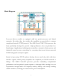
Operation Manual of EX-9132C-2
Serial to TCP/IP Converter
Version 1.1.0 , 25th Jan. 2010
Table of Contents
1. Introduction
Overview
………………………………………………
3
………………………………………………………
4
Package Checklist
Block Diagram
Features
……………………………………………… 4
…………………………………………………
5
………………………………………………………… 6
Product Specifications
…………………………………………
2. EX-9132C-2 Description
Product Panel Views
7
...................................…………… 9
…………………………………………… 9
Top Side ………………………………………………………… 9
Right Side
Left Side
………………………………………………………
9
………………………………………………………… 10
Rear Side
………………………………………………………
10
LED Indicators ………………………………………………… 11
Wiring Architecture
RS-232
…………………………………………… 12
…………………………………………………………
RS-422/RS-485
…………………………………………………
3. EX-9132C-2 Installation
................................……………
12
12
13
Power Supply
…………………………………………………… 13
Ethernet Port
…………………………………………………… 13
Serial Port
………………………………………………………
RS-485/RS-422 Port
Dip Switch
Reset
……………………………………………
14
14
……………………………………………………… 14
……………………………………………………………
1
14
4. EX-9132C-2 Configuration
Initial IP Configuration
...................................……… 16
...……………………………………… 16
Device Management Utility of EXBrowser ……………………… 16
Menu “View”
…………………………………………………… 18
Menu “Config”
…………………………………………………
18
Web Console Configuration …………………………………
20
Controller Status
………………………………………………
21
Controller Setup
………………………………………………
24
Controller Updated
……………………………………………
30
Factory Default Setting
………………………………………
31
5. Setting Verification
……………………………………
32
Hyper Terminal for TCP/IP WinSock
………………………
33
Hyper Terminal for COM Port ………………………………
38
Data Transmission
……………………………………………
39
Appendix A - FAQ …………………………………………
Appendix B - Pin Outs and Cable Wiring …………
40
B.1 DC-In Jack ………………………………………………
41
B.2 RJ-45 Pin Assignment
41
……………………………………
41
B.3 RS-232 Pin Assignment …………………………………
41
B.4 RS-232 Wiring Diagram
42
…………………………………
B.5 RS-422 Pin Assignment …………………………………
42
B.6 RS-422 Wiring Diagram
…………………………………
42
B.7 RS-485 Wiring Diagram
…………………………………
42
2
1
Introduction
We provide new ways of connecting legacy serial devices to a Local Area Network (LAN)
or Wide Area Network (WAN). TCP/IP converters are designed to operate serial ports over
100M bps Ethernet networks. The data is transmitted via TCP/IP protocol. Therefore,
control is available via Ethernet, Intranet and Internet. EX-9132C-2 converter is packaged in
a PVC material case well suited for industrial environments. It provides two serial ports one
is a RS-232 and another is RS-232/422/485 (Auto-Detect). All serial ports operate in
common industrial configuration.
EX-9132C-2 converter is a low-cost, high performance design. By carefully selecting high
quality with competitive prices components in the world, the products made network
connectivity possible with affordable cost for virtually all kinds of devices.
EX-9132C-2 is a full set converter device with two serial ports as one is a RS-232 port and
another is a RS-232/422/485 (Auto-Detect) and it provides one socket per connection port.
This operation manual will guide you step by step to learn the various functions of the
EX-9132C-2 converter.
The following topics are covered in this chapter:
□□ Overview
□□ Block Diagram
□□ Product Features
□□ Product Specifications
3
Overview
EX-9132C-2 converter is designed to make your industrial serial devices Internet ready
instantly. ARM Cortex-M3 CPU of EX-9132C-2 converters makes them the ideal choice for
connecting your RS-232 and RS-422 or RS-485 serial device—such as PLCs, meters, and
sensors—to an IP-based Ethernet LAN, making it possible for your software to access
serial devices anywhere and anytime over a local LAN or the Internet.
ARM Cortex-M3 CPU Series converters ensure the compatibility of network software that
uses a standard network API (Winsock or BSD Sockets) by providing TCP Server Mode,
TCP Client Mode, and UDP Mode. Model EX-9132C-2 provides 1 socket connection for
remote management. ARM Cortex-M3 CPU Series’ Virtual COM driver and software that
works with COM port can be set up to work over a TCP/IP network in no time. This
excellent feature preserves your software investment and let you enjoy the benefit of
networking your serial devices instantly.
ARM-Cortex-M3 CPU series converter supports manual configuration via the handy web
browser console and many protocols including TCP, IP, UDP, HTTP, DHCP, ICMP, and
ARP. They are the best solution to network your serial devices.
Package Checklist
ARM-Cortex-M3 CPU products are shipped with the following items:
□□ 1 unit of EX-9132C-2 converter
□□ 1 unit of Power Adaptor (9V DC, 500mA) : Optional
□□ Quick Installation Guide in Documentation & Software CD
NOTE: Please notify your sales representative if any of the above items is missing or
damaged.
4
Block Diagram
Low-cost devices usually are equipped with low speed processors and limited
memories. In reality, they have neither the capability nor practicality to manage
complicated network TCP/IP protocols. The ARM Cortex™-M3 32-bit processor has
been specifically developed to provide a high-performance, low-cost platform for a
broad range of applications including microcontrollers, automotive body systems, and
industrial control systems, networking by converting data stream between network
TCP/IP and popular serial port signals.
Instead of processing TCP/IP packets directly, devices need only deal with those
interface signals, which greatly simplifies the complexity of TCP/IP network in
linkage. The ARM Cortex-M3 processor provides outstanding computational
performance and exceptional system response to interrupt while meeting low cost
requirements through small core footprint, industry leading code density enabling
smaller memories, reducing pin count, and low power consumption.
5
The central core of ARM Cortex-M3 processor, based on a 3-stage pipeline
Harvard bus architecture,
incorporates advanced features including
single
cycle
multiply and hardware divide to deliver an outstanding efficiency of 1.25
DMIPS/MHz. The ARM Cortex-M3 processor also implements the new Thumb®-2
instruction set architecture, which combined with features such as unaligned data
storage and atomic bit manipulation delivers 32-bit performance at a cost equivalent to
modern 8- and 16-bit devices.
6
Product Features
□□ Data Conversion between RS-232 and RS-422/485 and Ethernet
EX-9132C-2 converter device (RS-232*1 port , RS-232/422⁄485*1 port ) data/signal
into the TCP/IP package data/signal and send them out with the Ethernet Data Stream; or
convert the TCP/IP package data/signal into serial device data/signal.
□□ Socket Communication
EX-9132C-2 is provided one socket connection.
□□ Digital I/O Activating (Optional)
EX-9132C-2 provides eight TTL of digital I/O.
Convert the sensors’ statuses (the sensors are connected to the converter) into the TCP/IP
package data and send them out with the Ethernet Data Stream; or use the TCP/IP
package data to activate/deactivate the specified digital outputs.
□□ Dynamic IP Configuration
Support DHCP client mode, simplifying network address configuration and management.
□□ Dual LAN Speed
Support 10/100 Mbps Ethernet, auto-detected.
□□ Server / Client Dual Modes
EX-9132C-2 converter device can be configured as network server or network client. In
the client mode, it can be installed in network which is protected by NAT router or
firewall without a real IP address.
□□ Web-based Setup
Parameters setup is based on HTTP protocol by using standard browsers (IE and
Netscape). No special software would be required.
□□ Built-in Security Control
Security protect by login password to prevent intruders.
□□ Remote Update
Firmware can be updated directly via Ethernet network to keep up with latest network
standards.
7
Product Specifications
CPU : ARM Cortex™-M3 32-bit processor , 50MHz
RAM : 64K Bytes SRAM
ROM : 256K Bytes Flash ROM
Ethernet
● Port Type : RJ-45 Connector
● Speed : 10 /100 M bps
( Auto Detect )
● Protocol : ARP, IP, ICMP, UDP, TCP, HTTP, DHCP, ICMP
● Mode : TCP Server∕TCP Client∕UDP Client / Virtual COM / Pairing
● Setup : HTTP Browser Setup (IE & Netscape)
● Security : Login Password
● Protection : Built-in 1.5KV Magnetic Isolation
Serial Port
● No. of Ports : RS-232*1 Port and RS-232/422/485(Auto-Detect) * 1 Port
● Port Type:DB9 male * 1 and Terminal Block(7pin) * 1
● Speed:300 bps∼115.2K bps
● Parity:None , Odd , Even, Mark, Space
● Data Bit:5, 6, 7, 8
● Stop Bit:1 , 2
● Port 1:
One RS-232 Signals Port:Rx , Tx , GND , RTS , CTS , DTR , DSR , DCD
● Port 2:
One RS-232/422⁄485 Port (Auto-Detect)
RS-232 Signals:Rx, Tx, GND
8
RS-422 Signals:Rx+ , Rx- , Tx+ , Tx- (Surge & Over Current Protect)
RS-485 Signals : Data+ , Data- (Surge & Over Current Protection)
Built-in RS422/RS485 Pull High-Low Resistor
Digital I/O Port
Digital TTL I/O * 8 pins
Socket Port Connection:1 Connection
15KV ESD for all signal
Watch Dog Function
Virtual Support Windows 2000 /2003 / XP / Vista / 7
Firmware On-line Updated Via Ethernet
Power:DC 9 – 24 V , 500mA
LED Lamp:
PWR (Green)
DATA (Red-Blink during data transferring and receiving)
LAN (Red for 10 Mbps ; Green for 100 Mbps)
SYS (Red-Blink)
Environment:
Operating Temperature:0℃∼70℃
Storage Temperature:-10℃∼80℃
Dimensions:115 * 90 * 27 mm ( W * D * H )
WEIGHT:140 gm
RoHS:Compliant with RoHS
Regulatory Approvals:FCC, CE
WARRANTY:1 year
9
2
EX-9132C-2 Description & Installation
Product Panel Views
Top Side
DC-In
Power Outlet
Ethernet LAN Port
Reset Button
Serial I/O Port
RS-232/485/RS-422
Serial I/O Port
RS-232
LED Indicators
Right Side
Serial I/O Port of RS-232 and RS-232/422/485
Connect the serial data cable between the converter device and the serial devices.
Follow the parameter setup procedures to configure the converter (see the following
chapters).
RS-232/485/422
RS-232
10
Digital I/O
Through EX-9132C-2 , D I/O can transform the status of sensor into the TCP/IP
package data and send out by Ethernet Data Stream (The EX-9132C-2 must
indicate the IP address and COM Port) or activate the indicated Digital output
(Remote WinSock must indicate the EX-9132C-2). Connect the data wires between
the EX-9132C-2 and the RS-485/RS-422 device. Follow the parameter setup
procedures to configure the converter (see the following chapters).
11
Left Side
Power Supply
EX-9132C-2 TCP/IP converter device is powered by a single 9VDC (inner
positive/outer negative) power supply and 500mA of current. A suitable power supply
adapter is part of the packaging. Connect the power line to the power jack at the left
side of EX-9132C-2 TCP/IP converter device and put the adapter into the socket. If
the power is properly supplied, the “PWR” red color LED will be on..
DC-In
Power Outlet
Ethernet LAN Port
Reset Button
Ethernet LAN Port
The connector for network is the usual RJ45. Simply connect it to your network
switch or Hub. When the connection is made, the LAN LED indicator will light up.
When data traffic occurs on the network, red DATA LED indicator will blink during
data transferring and receiving.
Reset Button
If you forget the setup password or have incorrect settings which makes e-Net TCP/IP
converter inoperable. First, turn off the power. Second, use any point tip to push this
button and hold it to turn on the power at the same time for 5 second.
parameters will be reset to the factory default.
12
All the
LED Indicators
PWR (Red):
It is a power indicator (When the power is on, the LED will be on.)
Tx (Green):
Data transmitting indicator (When data are sending to the network, the LED will
blink.)
Rx (Red):
Data received indicator (When data are receiving by the network, the LED will blink.)
SYS (Green):
It is a device statues indicator (When EX-9132C-2 is operated in normal statues, the
LED will blink once per second.)
13
Wiring Architecture
RS-232 Wiring Architecture
RS-422/RS-485 Wiring Architecture
14
When you finish the steps mentioned above and the LED indicators are as shown in above
diagram, the converter is installed correctly.
You can use the Setup Tool “EXBrowser.exe”
to setup the IP Address.
To proceed the advanced parameter setup, please use a web browser (IE or Netscape) to
continue the detailed settings.
15
3
EX-9132C-2 Converter Configuration
Initial IP Configuration
When sett up your converter for the first time, the first thing you should do is to configure
the IP address. This chapter introduces the method to configure the device server’s IP
address.
For more details about network settings, please see the Network Settings section
in Chapter3, “Web Console Configuration”.
The following topics are covered in this chapter:
□□ Device Management Utility
□□ EXBrowser “View”
□□ EXBrowser “Modify IP”
□□ EXBrowser “Modify MAC”
Device Management Utility
On PC we provide a Device Management Utility named “EXBrowser.exe” which is an
executable program in Windows 32-bit environments. EXBrowser setup tool is used to
detect and setup the installed converters.
It uses UDP broadcast packets to query and
configure converters on the network.
16
When you activate the tool, it will detect the existence of the installed converters and
depict the converters’ status such as IP address, Subnet Mask, MAC Address, and
Device ID (see Figure 3.1).
The Setup Tool only can setup one converter at a time.
Thus if there are more than one converter on the network, please shut down or
disconnect other converters. Otherwise the EXBrowser.exe can not detect the converter.
Due to the nature of broadcast UDP packets, EXBrowser has following characteristics:
□□ Broadcast packets are not limited by subnet. Even if the IP address of the converters
and the computer running EXBrowser that do not belong to the same subnet, it still
works fine.
□□ Broadcast packets can not pass routers. EXBrowser can only be used to monitor
devices with computer running EXBrowser in the same segment of local area
network.
(Figure 3.1)
17
EXBrowser “View”
□□ View -> Refresh
There are two ways for refreshing the status of existing devices. You may
select the item “View” to refresh the status of existing devices on LAN.
Another is to click the icon as red color remark as below. EXBrowser will send
another query to get updated information. (see Figure 3.2).
Note: Always run the “Refresh” after any data change.
(Figure 3.2)
□□ File -> Exit
Alt+F4
Exit from the program (see Figure 3.3).
(Figure 3.3)
EXBrowser “Modify IP”
□□ Modify IP -> Dialog Frame
To click the device on the existing devices list in the EXBrowser table and then the
function bar will be enable. To press second icon of “Modify IP” on function bar
and a dialog frame table will be shown (see Figure 3.4).
18
(Figure 3.4)
Assign an IP Address with the same Subnet Mask of your computer, avoiding any
IP conflict with other network devices.
When you press “Confirm” button, the IP address will be refreshed in 2~3 seconds.
(Figure 3.5)
After click “Confirm” button and then “Input Password” request will be pop-up on
screen (see Figure 3.5). Please simply press “Confirm” button and the new device’s
IP will be changed and save in table, if you changed it.
(Figure 3.6)
19
EXBrowser “Modify MAC”
□□ Modify MAC -> Dialog Frame
To click the device on the existing devices list in the EXBrowser table and then the
function bar will be enabled. To press Third icon of “Modify MAC” on function
bar and a dialog frame table will be shown (see Figure 3.7).
(Figure 3.7)
□□ Input Password -> Dialog Frame
After click “Confirm” button and then “Input Password” request will be pop-up on
screen (see Figure 3.8). Please simply press “Confirm” button and the new device’s
MAC will be changed and save in table, if you changed it.
(Figure 3.8)
20
Web Browser Configuration
The following topics are covered in this chapter:
□□ Serial To Ethernet Converter Setup
●
Login Setting
●
Login Setting Page Field Description
●
Parameter Setting
●
Parameter Setting Page Field Description
Login Setting
In addition to basic IP address and subnet mask, specific device settings can be set
through HTTP protocol with popular browsers, e.g. Internet Explorer, Netscape,
etc. Setup of the converters is as easy as surfing on WWW, no special software
will be required.
Setup converter device is as easy as surfing on WWW; no special software will be
required. Popular Browsers, such as IE, or Netscape, can easily do the setup
process. In the browser URL field, set the IP address of device directly, to enter
the “Login Setting” page, please follow the steps below.
□□ Open your browser. This chapter will use IE as an example.
□□ In the browser URL field, type the IP address of the converter directly and
press ENTER. (The IP address is what you set using the Device Management
Utility as EXBrowser.)
□□ To press fourth icon of “Web Browser” on function bar and a “Login
Setting” Screen will be shown (see Figure 3.9) to login into the device.
Alternatively, if the IP address of the converter is already known, you can
connect to the converter directly by providing its IP address in the URL field
21
of browsers.
(Figure 3.9)
Login Setting Page Field Description
□□ System time elapsed
The time elapsed since start of this device in [Day Hour : Minute : Second]
format. This information can be useful in identifying the reliability of system.
□□ Firmware version
Converter firmware is identified by date code. This information will be required
looking for technical support.
□□ Serial number
It is a product serial number code in the converter device and has been provided
by factory.
22
□□ Ethernet MAC Address
Converter is a unique MAC (Media Access Control) address used by Ethernet.
□□ Password
This field is the administration password for authentication. Factory default is
“empty”. However, it is not recommended to leave it empty in field operation.
If you could not login, it means you have to key in the password. If you do not
know the password you can turn off the power and then use any point tip to
push “Reset” button and hold it to turn on the power at the same time for 5
seconds.
The password will be reset to the factory default as “empty”.
Converter device uses the same password protection mechanism commonly
used in Windows NT or UNIX. If there are more than “3 consecutive failures”
in password check during login, the login function will be disabled for “15
minutes”. During this 15 minutes period, even if you supply correct password,
login will not proceed. This prevents intruders from finding the password by
computer generated program.
23
Parameter Setting Page
□□ The Parameter Setting Page
Type the correct password in the “Password” field and click the “Confirm”
button in the “Login Setting” page, then the “Parameter Setting” page will be
shown (see Figure 3.10).
Note: If you forget the password or can’t login successfully, please contact the
manufacturer directly.
(Figure 3.10)
24
□□ Parameter Setting Page Field Description
□□ IP Address
The IP address of converter device, 4 digits separated by '.'
conflict with the other devices on the network.
Don’t let it
If DHCP client mode is enabled and there's a DHCP server on the network, this
field will be assigned by DHCP server automatically.
□□ Subnet mask
Subnet mask of the converter device has connected to. “255.255.255.0” is
usually used for small network, “255.255.0.0” for larger network, 4 digits
separated by '.'
If your IP address is provided by an ISP or the internal network administrator,
please inquire of them that information and type it correctly.
If DHCP client mode is enabled and there's a DHCP server on the network, this
field will be assigned by DHCP server automatically.
□□ Gateway address
Gateway or Router IP address. 'Gateway' is a device which connects local
network to external network. If you need to communicate with other networks
or your device owns a real IP address on the internet, please inquire of them that
information and type it correctly. If there's no gateway on the network, just
leave it as “0.0.0.0”.
If DHCP client mode is enabled and there's a DHCP server on the network, this
field will be assigned by DHCP server automatically.
□□ DHCP client
DHCP client mode could be enabled/disabled statues. If DHCP is enabled, there
should be a DHCP server on the network. If DHCP is disabled, [IP address],
[Subnet mask], and Gateway address] should be manually assigned.
□□ Auto Reset
It is for resetting when the device has been disconnected or some reasons, the
data stop transmitting for a while. You can prevent it and restart the device after
waiting a while (1∼99 hours) as your settings.
25
□□ Device ID Report
You may “Enable” or “Disable” to collect the device ID report and assigne ID
number for the converter devices. Available ID is “0 ~ 65535”. In TCP mode, if
this parameter is enabled, every time when the socket is connected, e-Net
TCP/IP converter will immediately report its device ID in the following
formats:
Serial #1
nnnnnA[LF][CR]
Serial #2
nnnnnB[LF][CR]
Digital I/O
nnnnnC[LF][CR]
The total length is 8 bytes, where “nnnnn” is a 5-digit device ID assigned by the
user; [LF] is decimal 10; [CR] is decimal 13.
.
□□ Login Password
For security and management issues, you may setup the “Login Password”.
This administration password uses to login converter parameter setting pages. It
may be empty or up to 15 characters long.
□□ Serial I∕O Port 1 (RS-232)
This converter device model provides one serial port as RS-232 interface for
connecting the extension serial device.
□□ Local Port ⁄ Socket Mode ⁄ Remote IP & Port
This converter devoice provides one socket connections port.
□□ Port number
A socket port assigned for the serial port. It’s a 16-bit numbers,
ranging from 1 to 65535. Because the numbers below 1000 are used for
specific purposes (e.g. 80 is for HTTP protocol), we suggest you use
the numbers larger than 1000. Generally the port number 4660 is used
for the serial communication. However you should specify different
port number for each serial port.
□□ Socket type
TCP Server: TCP protocol, passive open, to be connected from the
TCP clients.
TCP Client: TCP protocol, active open, connect to the TCP server
UDP Client: UDP protocol, connectionless
□□ Remote IP address
26
The server IP address and socket port would be connected in TCP
Server, TCP Client and UDP Client mode for a certain serial port.
□□ Remote socket port
The server socket port would be connected in TCP Client and UDP
Client mode for a certain serial port.
□□ Interface of serial I/O
RS232:TxD, RxD for data stream, no flow control
RS232 (RTS/CTS):TxD, RxD for data stream, RTS/CTS for flow
control.
□□ Baudrate
Baud Rate: 300 ~ 115.2K bps
□□ Parity, Data bits, Stop bit
Parity: None, Even, Odd, Space, Mark.
Data Bits: 5, 6, 7, 8.
Stop Bit: 1 or 2.
□□ Force off-line time
It is for setting the off-line time period of device will be taken when
there is no date input. The parameter can be from “0 to 99” and the
time unit is “Minute”.
□□ Packet Collect Time
It is for setting a packet collecting period of the device serial port’s Tx
and Rx. The parameter can be from “0 to 999” and the time unit is
“mSec”.
□□ Serial I/O Port 2 (RS-232/422/485)
This converter device model is provided second serial port as RS-232/422/485
(Auto-Detect) interfaces for connecting the extension serial device.
□□ Local Port ⁄ Socket Mode ⁄ Remote IP & Port
This converter device provides 1 socket connection port.
□□ Port number
27
A socket port is assigned for the serial port. It’s a 16-bit numbers,
ranging from 1 to 65535. Because the numbers below 1000 are used for
specific purposes (e.g. 80 is for HTTP protocol), we suggest you use
the numbers larger than 1000. Generally the port number 4660 is used
for the serial communication. However you should specify different
port number for each serial port.
□□ Socket type
TCP Server: TCP protocol, passive open, to be connected from the
TCP clients.
TCP Client: TCP protocol, active open, connects to the TCP server.
UDP Client: UDP protocol, connectionless
□□ Remote IP address
The server IP address and socket port would be connected in TCP
Client and UDP Client mode for a certain serial port.
□□ Remote socket port
The server socket port would be connected in TCP Server, TCP Client
and UDP Client mode for a certain serial port.
□□ Interface of serial I/O
It provides an “Auto Detect” function and just depends on the
connected serial device’s interface as RS-422 or RS-485.
□□ Baudrate
Baud Rate: 300 ~ 115200 bps
□□ Parity, Data bits, Stop bit
Parity: None, Even, Odd, Space, Mark.
Data Bits: 5, 6, 7, 8.
Stop Bit: 1 or 2.
□□ Force off-line time
It is for setting the off-line time period of device will be taken when
there is no date input. The parameter can be from “0 to 99” and the
time unit is “Minute”.
□□ Packet Collect Time
It is for setting a packet collecting period of the device serial port’s Tx
and Rx. The parameter can be from “0 to 999” and the time unit is
“mSec”.
28
□□ Interface of serial I/O
RS-232: TxD, RxD for data stream, no flow control
RS-232 (RTS/CTS): TxD, RxD for data stream, RTS/CTS for flow
control
RS-485 (Half-duplex): Half-duplex RS-485 interface, RTS for
driver enable/disable
RS-422 (Full-duplex): Full-duplex RS-422 interface
29
Controller Updated
Press “Update”] Button after finish the detailed parameter setting. The converter
will save all parameters into internal non-volatile memory and then reboot (see
Figure 5.3). It takes about 5 seconds to complete the whole process, and a new
login page will be presented (see Figure 5.1).
(Figure 5.3)
You can re-login and check if all parameters have been correctly saved. If
everything is ok, you can close the browser now.
Note : If the domain of the converter is different from that of the computer
running the browser, the login page won’t appear unless the converter’s
“Gateway Address” has been correctly set.
30
Factory Default Setting
If you forget the setup password or have incorrect settings making the converter
inoperable, there are two ways to reset the setting and the following procedures
can be used to reset all settings to factory default:
A:
1. Please turn on the power and then use any point tip to push “Reset” button
for 5 seconds. The password will be reset to the factory default as
“empty”.
31
1.
5
Setting Verification
After complete the wiring and parameter setting, we should verify if the setting is
correct. This chapter will introduce how to use a single computer to test if the
converter behaves well.
The operating system can be Windows 95, 98, ME, XP, 2000, Vista, 7. The “Hyper
Terminal” utility should be installed on your PC (see Figure 6.1).
It can be found
in your Windows installation CD.
The wiring architecture is similar to “RS-232 Wiring” in chapter 3, and the “Serial
Device” is replaced by the PC’s COM 1.
The same PC also plays the roll of the
Remote Host.
The following topics are covered in this chapter:
□□ Hyper Terminal for TCP/IP WinSock
□□ Hyper Terminal for COM Port
□□ Data Transmission
32
Hyper Terminal for TCP/IP WinSock
Initiate a Hyper Terminal from the Start Menu in Windows (see Figure 6.1), give a
terminal name, choose an icon, and press “OK” button (see Figure 6.2).
(Figure 6.1)
33
(Figure 6.2)
Select “TCP/IP (Winsock)” option at the “Connect using:” field (see Figure 6.3).
34
(Figure 6.3)
After “OK” button is pressed, Figure 6.4 appears.
Enter the converter’s IP address (e.g.
192.168.123.10) at the “Host address:” field, and the Socket port number set for the
Serial Port 1 at the “Port number:” field (e.g 4660).
1 should be “TCP Server”.)
35
(The Socket type of the Serial Port
(Figure 6.4)
After “OK” button is pressed, Figure 6.5 appears. If the Hyper Terminal connects with
the converter successfully, the time clock at the left lower corner “Connected hh:mm:ss”
will start counting.
36
(Figure 6.5)
37
Hyper Terminal for COM Port
Initiate another Hyper Terminal as a COM Port Terminal (in Figure 6.3, select COM 1 or
other COM port instead of “TCP/IP (Winsock)”).
Set the COM port Properties to be
the same as those set for the Serial Port 1 of the converter.
(Figure 6.3)
38
Data Transmission
When all steps described above are finished, type any texts on the COM Port Terminal
and check if the texts are also displayed on the TCP/IP Winsock Terminal.
Alternatively, check if the characters typed on the TCP/IP Winsock Terminal are also
displayed on the COM Port Terminal.
If yes, then all settings are correct and the
converter can operate properly.
39
Appendix A
FAQ
Q. Why can’t the EXBrowser.exe detect the converter on the network?
A. Please check
□□ if the power is properly plugged to the converter.
□□ if the network cable is properly connected between the converter and the Hub.
Please refer to the “Hardware Installation” steps in Chapter 3.
Q. Why can’t I use IE to setup the converter?
A. Please check if the network domain of your PC is the same as that of the converter.
40
Appendix B
Pin outs and Cable Wiring
□□ DC-In Jack
□□ RJ-45 Pin Assignment
□□ RS-232 Pin Assignment
The pin assignment scheme for a 9-pin male connector on a DTE is given
below.
PIN 1 : N/A
PIN 2 : RXD
PIN 3 : TXD
PIN 4 : DTR
PIN 5 : GND
PIN 6 : DSR
PIN 7 : RTS
PIN 8 : CTS
PIN 9 : N/A
41
□□ RS-232 Wiring Diagram
EX-9132C-2
Serial Device
2 RX
3 TX
5 GND
7 RTS
8 CTS
3
2
5
8
7
TX
RX
GND
CTS
RTS
□□ RS-422 Pin Assignment
The pin assignment scheme for a 4-pin RS-422 is given below.
1
PIN 1 : R-
2
3
4
PIN 2 : R+
PIN 3 : T-
PIN 4 : T+
□□ RS-422 Wiring Diagram
EX-9132C-2
Serial Device
RR+
TT+
3
4
1
2
TT+
RR+
□□ RS-485 Wiring Diagram
EX-9132C-2
Serial Device
D+
D-
D-
D42