1
USER'S MANUAL 990-660 Revision C October 2007 MODEL DC25 LINEAR DC RESISTANCE WELDING CONTROL MODEL NUMBER DC25 DC25/230 STOCK NUMBER 1-283-01 1-283-01-01 Copyright © 2001 Unitek Miyachi Corporation The engineering designs, drawings and data contained herein are the proprietary work of UNITEK MIYACHI CORPORATION and may not be reproduced, copied, exhibited or otherwise used without the written authorization of UNITEK MIYACHI CORPORATION. Printed in the United States of America. REVISION RECORD Revision EO Date Basis of Revision A 18122 12/01 Original Release B 19166 12/01 Energy Capacity % Limit change. C 21594 10/07 Updated Technical Specifications. MODEL DC25 LINEAR DC RESISTANCE WELDING CONTROL ii 990-660 FOREWORD Thank you for purchasing a Unitek Peco¥ DC25 Linear DC Welding Control. Upon receipt of your equipment, please thoroughly inspect it for shipping damage prior to its installation. Should there be any damage, please immediately contact the shipping company to file a claim, and notify us at: Unitek Miyachi Corporation 1820 South Myrtle Avenue P.O. Box 5033 Monrovia, CA 91017-7133 Telephone: (626) 303-5676 FAX: (626) 358-8048 e-mail: [email protected] The purpose of this manual is to supply operating, maintenance and service personnel with the information needed to properly and safely operate, maintain and service the DC25 Linear DC Welding Control. We have made every effort to ensure that the information in this manual is accurate and adequate. Should questions arise, or if you have suggestions for improvement of this manual, please contact us at the above location/numbers. Unitek Miyachi Corporation is not responsible for any loss due to improper use of this product. MODEL DC25 LINEAR DC RESISTANCE WELDING CONTROL 990-660 iii SAFETY NOTES This instruction manual describes how to operate and maintain the DC25 Linear DC Welding Control and provides instructions relating to its SAFE use. Procedures described herein MUST be performed, as detailed, by QUALIFIED and TRAINED personnel. For SAFETY, and to effectively take advantage of the full capabilities of the workstation, please read this instruction manual before attempting to use the DC25 Linear DC Welding Control. Procedures other than those described in this manual, or not performed as prescribed in it, may expose personnel to electrical hazards. After reading this manual, retain it for future reference when any questions arise regarding the proper and SAFE operation of the unit. Please note the following conventions used in this manual: WARNING: Comments marked this way warn the reader of actions which, if not followed, might result in immediate death or serious injury. CAUTION: Comments marked this way warn the reader of actions which, if not followed, might result in either damage to the equipment, or injury to the individual if subject to long-term exposure to the indicated hazard. MODEL DC25 LINEAR DC RESISTANCE WELDING CONTROL iv 990-660 Table of Contents Page Chapter 1: Description ................................................................................................................ 1-1 Section I: Introduction ................................................................................................................ 1-1 Features ..................................................................................................................................... 1-1 Applications .............................................................................................................................. 1-2 Section II: Description ................................................................................................................. 1-3 Section III: Overview .................................................................................................................... 1-4 Introduction .............................................................................................................................. 1-4 LCD Screens ............................................................................................................................. 1-4 Menu Screens ..................................................................................................................................1-5 Data Screens ...................................................................................................................................1-5 Alphanumeric Data ................................................................................................................... 1-5 Operational States ..................................................................................................................... 1-5 Graphed Data ............................................................................................................................ 1-7 Section IV: Controls And Indicators ............................................................................................. 1-8 Introduction .............................................................................................................................. 1-8 Liquid Crystal Display (LCD) And Weld Selector Keys ......................................................... 1-8 Numeric Keypad And Operational Controls .......................................................................... 1-10 Section V: Emergency Stop Switch And 24V Jumpers ............................................................. 1-13 Section VI: Related Publications ................................................................................................. 1-14 Chapter 2: Getting Started ......................................................................................................... 2-1 Section I: Planning For Installation ............................................................................................ 2-1 Space Requirements ................................................................................................................. 2-1 Utilities ..................................................................................................................................... 2-1 Section II: Unpacking .................................................................................................................. 2-2 Section III: Electrical And Data Connections ............................................................................... 2-3 Section IV: Setup ........................................................................................................................... 2-5 Manual Weld Head Connections .............................................................................................. 2-5 Air-Actuated Weld Head Connections...................................................................................... 2-7 Relay, Data, And Communication Connections ....................................................................... 2-8 Chapter 3: Using DC25 Welding And Monitoring Functions ................................................. 3-1 Section I: Introduction ................................................................................................................ 3-1 Section II: Weld Schedules .......................................................................................................... 3-2 Definition .................................................................................................................................. 3-2 Weld Sequence Timing ............................................................................................................ 3-2 Welding Applications ............................................................................................................... 3-3 Weld Head Applicability .......................................................................................................... 3-3 Single-Pulse Weld Profile ........................................................................................................ 3-4 Applications ...................................................................................................................... 3-4 Description ........................................................................................................................ 3-4 MODEL DC25 LINEAR DC RESISTANCE WELDING CONTROL 990-660 v Table of Contents (Continued) Page Upslope/Downslope Weld Profile Applications ...................................................................... 3-4 Applications ...................................................................................................................... 3-4 Description ........................................................................................................................ 3-4 Dual-Pulse Weld Profile ........................................................................................................... 3-5 Applications ...................................................................................................................... 3-5 Description ........................................................................................................................ 3-5 Section III: Programmable Feedback Modes ................................................................................ 3-7 Introduction .............................................................................................................................. 3-7 Current Mode ............................................................................................................................ 3-7 Applications ...................................................................................................................... 3-7 Description ........................................................................................................................ 3-7 Voltage Mode ........................................................................................................................... 3-7 Applications ...................................................................................................................... 3-7 Description ........................................................................................................................ 3-7 Power Mode .............................................................................................................................. 3-7 Applications ...................................................................................................................... 3-7 Description ........................................................................................................................ 3-7 Section IV: Weld Monitor ............................................................................................................. 3-8 Introduction .............................................................................................................................. 3-8 Active Part Conditioner (APC) ................................................................................................ 3-8 Applications ...................................................................................................................... 3-8 Description ........................................................................................................................ 3-8 How It Works .................................................................................................................... 3-9 Instructions ............................................................................................................................. 3-10 Energy Limits ................................................................................................................................ 3-10 Applications .................................................................................................................... 3-10 Description ...................................................................................................................... 3-10 Pre-Weld Check ............................................................................................................................. 3-11 Application ...................................................................................................................... 3-11 Function ........................................................................................................................... 3-11 Chapter 4: Operating Instructions ............................................................................................ 4-1 Section I: Introduction ................................................................................................................ 4-1 Section II: Initial Setup ................................................................................................................ 4-2 Pre-Operational Checks ............................................................................................................ 4-2 Connections ....................................................................................................................... 4-2 Power ................................................................................................................................. 4-2 Compressed Air ................................................................................................................. 4-2 Initial Setup Instructions .......................................................................................................... 4-2 MODEL DC25 LINEAR DC RESISTANCE WELDING CONTROL vi 990-660 Page Section III: Programming Weld Schedules ................................................................................... 4-3 Introduction .............................................................................................................................. 4-3 Select A Weld Schedule .................................................................................................... 4-3 Enter New Values .............................................................................................................. 4-3 Single-Pulse Weld Schedule ..................................................................................................... 4-4 Upslope/Downslope Weld Schedule ........................................................................................ 4-5 Dual-Pulse Weld Schedule ....................................................................................................... 4-6 Section IV: Programming The Weld Monitor ............................................................................... 4-7 Section V: Programming For Active Part Conditioning ............................................................ 4-10 Section VI: Operation .................................................................................................................. 4-12 General Operator Safety ......................................................................................................... 4-12 Manual Welding ..................................................................................................................... 4-12 Operation ......................................................................................................................... 4-12 Normal Stop .................................................................................................................... 4-12 Automated Welding ................................................................................................................ 4-12 Operation ......................................................................................................................... 4-12 Normal Stop .................................................................................................................... 4-13 Emergency Stop .............................................................................................................. 4-13 Re-Set After Emergency Stop ......................................................................................... 4-13 Chapter 5: Setup Software .......................................................................................................... 5-1 Section I: Introduction ................................................................................................................ 5-1 Overview .................................................................................................................................. 5-1 Section II: How To Use Menu Screens ....................................................................................... 5-2 Main Menu ............................................................................................................................... 5-2 Setup Menus ............................................................................................................................. 5-2 Section III: Operator Preferences .................................................................................................. 5-4 Display Contrast ....................................................................................................................... 5-4 Buzzer Loudness ...................................................................................................................... 5-4 End Of Cycle Buzzer ................................................................................................................ 5-4 Update Graph After Weld ........................................................................................................ 5-5 Buzzer On Weld Stop ............................................................................................................... 5-5 Section IV: System Settings .......................................................................................................... 5-6 Waveform Check And Weld Fire Lockout ............................................................................... 5-6 Waveform Check ON/OFF ............................................................................................... 5-6 Stability Check % Limit Setting ........................................................................................ 5-6 Stability Check Delay Setting ........................................................................................... 5-7 Energy Capacity % Limit Setting ...................................................................................... 5-7 Weld Fire Lockout Charge % Setting ............................................................................... 5-8 Footswitch Weld Abort ............................................................................................................ 5-8 Switch Debounce Time ............................................................................................................ 5-9 Firing Switch ............................................................................................................................ 5-9 MODEL DC25 LINEAR DC RESISTANCE WELDING CONTROL 990-660 vii Table of Contents (Continued) Page Input Switch Select ................................................................................................................. 5-10 Mechanical Selection ...................................................................................................... 5-10 OPTO Selection ............................................................................................................... 5-11 PLC Selection ................................................................................................................. 5-11 Control Signals Select ............................................................................................................ 5-12 Weld Counter Functions ......................................................................................................... 5-12 System Security ...................................................................................................................... 5-13 Calibration .............................................................................................................................. 5-14 Chain Schedules ..................................................................................................................... 5-14 Section V: PID Test Weld Setup ................................................................................................ 5-17 Overview ................................................................................................................................ 5-17 Do Test Weld Options ............................................................................................................ 5-17 Ignore First/Last ..................................................................................................................... 5-18 Section VI: Relay Settings .......................................................................................................... 5-19 Function .................................................................................................................................. 5-19 Programming Instructions ...................................................................................................... 5-19 Section VII: Special Functions ..................................................................................................... 5-21 Copy A Schedule .................................................................................................................... 5-21 Reset Defaults ......................................................................................................................... 5-21 Reset System Parameters ................................................................................................ 5-23 Reset All Schedules ......................................................................................................... 5-23 Section VIII: Communication And Data ........................................................................................ 5-24 Requirements .......................................................................................................................... 5-24 Communication ...................................................................................................................... 5-24 I.D. Number ............................................................................................................................ 5-25 Baud Rate ............................................................................................................................... 5-25 Chapter 6: User Maintenance .................................................................................................... 6-1 Section I: Precautions ................................................................................................................. 6-1 Section II: Operator Maintenance ................................................................................................ 6-1 Section III: Troubleshooting ......................................................................................................... 6-1 General Kinds of Problems ...................................................................................................... 6-1 Soft .................................................................................................................................... 6-1 Hard ................................................................................................................................... 6-2 Alarm Messages ....................................................................................................................... 6-2 Troubleshooting ........................................................................................................................ 6-2 Technical Assistance ................................................................................................................ 6-5 Electrode Maintenance ............................................................................................................. 6-5 Parts Replacement .................................................................................................................... 6-6 MODEL DC25 LINEAR DC RESISTANCE WELDING CONTROL viii 990-660 Page Chapter 7: Calibration ................................................................................................................ 7-1 Section I: Introduction ................................................................................................................ 7-1 Overview .................................................................................................................................. 7-1 Calibration Equipment Required .............................................................................................. 7-1 Calibration Points ..................................................................................................................... 7-2 Section II: Calibration Equipment Setup ..................................................................................... 7-3 Section III: Calibration Procedure ................................................................................................ 7-4 Appendix A: Technical Specifications ......................................................................................... A-1 Appendix B: Electrical And Data Connectors .............................................................................B-1 Appendix C: The Basics Of Resistance Welding .........................................................................C-1 Appendix D: Quality Resistance Welding Solutions Defining The Optimum Process ............ D-1 Appendix E: LCD Display Messages ............................................................................................E-1 Appendix F: Relay Timing Diagrams ........................................................................................... F-1 Appendix G: Repetition Rates ...................................................................................................... G-1 MODEL DC25 LINEAR DC RESISTANCE WELDING CONTROL 990-660 ix CHAPTER 1 DESCRIPTION Section I: Introduction Features The DC25 Linear DC Welding Control is a Resistance Welding Control. For the rest of this manual, the DC25 will be referred to simply as the Control. The Control has the following features: x Programming of time in 10 μsec increments (minimum) provides shorter weld times, less part deformation, longer electrode life, and greater weld strength with more part ductility. x Built-in Liquid Crystal Display (LCD) shows a graphical "trace" of weld current, voltage, power and resistance, plus alphanumeric peak and average values. x Up to 99 individual Weld Schedules (sometimes referred to as weld profiles) can be programmed and stored. Weld schedules can be used individually or in sequence with others using the "chain schedules" function. You can also use schedule #00 as a "scratch pad" for developing schedules. x Easy-to-set limits establish process window for acceptable quality. x Weld limits and user programmable relays can be used in conjunction with visual and audible signals for operators and automation interface. x Active Part Conditioning (APC) compensates for varying part conditions and oxide layers. x Rear-mounted RS-232 and RS-485 connectors allow for remote programming, weld schedule selection, and data logging for SPC purposes. x Calibration traceable to NIST standards. x Optional DC25/DC25 Advanced Serial Datacom Communications Interface kit, commonly called "the Datacom kit," available for process logging. x Password protection provides process security. DC25 LINEAR DC RESISTANCE WELDING CONTROL 990-660 1-1 CHAPTER 1: DESCRIPTION Applications The Control is ideal for microjoining applications, which require exceptional control and highest quality throughput. The Control has a closed-loop feedback circuit that allows the user to program constant current, constant voltage, or constant power welding pulses. Chapter 3, Using DC25 Welding And Monitor Functions, describes the Control's functions and how to use them for different welding applications. The Control requires only single-phase input power and can supply weld power up to 4,000 amps. The advanced linear control circuit provides instantaneous update of the welding pulse in response to changes in the resistance of the work piece during the weld. This level of control is essential to achieve consistent welds in applications where the resistance changes dramatically. The graphical display and intuitive weld monitor make understanding the weld and the weld optimization process easy. Data output provides the necessary process documentation for critical applications and permits data logging for SPC purposes. DC25 LINEAR DC RESISTANCE WELDING CONTROL 1-2 990-660 CHAPTER 1: DESCRIPTION Section II: Description DC25 Front Panel The front panel contains all the controls and indicators necessary to operate the Control. You can program the Control using the data input keys and information appearing in the Liquid Crystal Display (LCD). Descriptions for each button and display are in Section IV of this chapter, Controls and Indicators. All electrical connectors, data connectors, and the ON / OFF switch are located on the rear panel of the Control. Connection instructions are described in Chapter 2, Getting Started. Complete technical specifications for the Control are listed in Appendix A, Technical Specifications. Connector pin identification and specifications are listed in Appendix B, Electrical And Data Connectors. DC25 LINEAR DC RESISTANCE WELDING CONTROL 990-660 1-3 CHAPTER 1: DESCRIPTION Section III: Overview Introduction The front panel of the Control contains the Liquid Crystal Display (LCD), and pushbutton keys (Weld Selector Keys, Numeric Keypad, and Operational Controls). Each is described in Section IV, Controls And Indicators. The LCD and the front panel keys are used together when programming and operating the Control. Instructions on how to do this are in Chapter 4, Operating Instructions. The LCD displays all of the setup, programming, and operating information for the Control. The front panel keys allow you to enter data for programming custom weld schedules, customizing the operating parameters of the Control, and operating your welding equipment. The keys also allow you to program the precise voltage, current, power, and time of each energy pulse into individual weld schedules, which may contain one or two weld pulses. Weld schedules consist of: x x x x Squeeze time before the weld pulse(s) [after the firing input is given] The time and energy for each weld period Cooling time between Pulse 1 and Pulse 2 [if two pulses are used] Hold time after the welding pulse(s) You can program and store up to 99 different weld schedules to meet a variety of welding applications. LCD Screens LCD Display Screens The LCD displays two types of screens: Data screens and Menu screens. NOTE: The purpose of this section is to describe the content of LCD screens. For clarity, LCD screens are shown here without the Weld Selector keys located directly under the display. DC25 LINEAR DC RESISTANCE WELDING CONTROL 1-4 990-660 CHAPTER 1: DESCRIPTION Menu Screens Menu screens are text screens that allow you to select and customize the operating parameters of the Control and performance of the welding equipment. Each menu screen lists several choices, with some offering additional menu screens listing more choices. The numeric keypad is used to select choices from the menu. Data Screens The Data screens display the information necessary to program, run, and monitor welds. Data is displayed in both alphanumeric and graphic form on the same screen. The graph displays time values from left to right, and energy values from bottom to top, showing the waveform of the weld schedule. The waveform gives you an easy-to-see "before and after" comparison of how you programmed the weld, and how the weld was actually performed. Alphanumeric Data Alphanumeric Data Alphanumeric data is displayed on three lines. Operating instructions will refer to alphanumeric data as the Top Line, Middle Line, and Bottom Line as shown above. Chapter 4, Operating Instructions, describes how to enter alphanumeric data, and how to select between voltage, current, power, peak/average display, and operational states. Operational States Each Data Screen displays the current operational state of the Control in the Top Line of data (left side). Menu Screens do not display the operational state, but the menu itself indicates the Control is in the MENU state. The following table describes each of the Control's operational states. DC25 LINEAR DC RESISTANCE WELDING CONTROL 990-660 1-5 CHAPTER 1: DESCRIPTION DC25 Operational States STATE DESCRIPTION RUN This state indicates the Control is ready to weld and waiting for a start signal. Press the RUN key on the front of the Control to put the Control in this state. NO WELD In this state, the Control does not deliver weld energy to the weld head heads in order to prevent electrical shock. This state is used for cleaning electrodes or adjusting the air regulators on air actuated weld. If a start signal is received, the Control will execute its programmed weld schedule(s) -- but no energy will go to the weld head, and the LCD will display a WELD SWITCH IN NO WELD POSITION alarm. The WELD/NO WELD switch toggles the Control between the WELD and NO WELD states. PROGRAM In this state, the weld time and energy values can be modified and new schedules can be selected. From the RUN state, press any one of the WELD SELECTOR KEYS to put the Control in the PROGRAM state. TEST When a weld schedule is changed, the Control has the capability of performing a TEST weld in order to optimize the feedback control loop and produce the fastest rise-time, minimum-overshoot weld pulse. The Control can be programmed to ALWAYS do a test weld after a schedule is changed, ASK to do a test weld after a schedule is changed, or only IF REQUIRED, do a test weld after a schedule is changed. STANDBY When an air actuated weld head is being used, the Control will go to the STANDBY state when the footswitch is pressed. SQUEEZE When a start signal has been received, the Control enters the SQUEEZE state for the duration programmed in the schedule. An adequate amount of squeeze time should be programmed to allow the weld head to settle before the WELD period begins. The default SQUEEZE time is 150 ms (milliseconds). NOTE: In addition to the debounce time, there is a delay of no greater than 2.5 ms before the start signal is recognized by the Control. WELD The WELD period begins after SQUEEZE time has ended and includes both weld pulses as well as the Cool time between Pulse 1 and Pulse 2. HOLD The HOLD period begins after the WELD period ends and lasts for the duration programmed in the schedule. An adequate amount of hold time should be programmed to allow the electrodes to sink the heat away from the welded parts. The default HOLD time is 50 ms. It is during the HOLD time that the weld strength is formed. END The Control will enter the END state after the HOLD period if the firing switch or footswitch has not yet been released. MONITOR This state allows you to view waveforms of weld voltage, current, power, and resistance. Press the ENERGY key to go to the MONITOR state. The LCD will show the actual trace of energy of the last weld performed. You can also view the peak or average energy value for each weld pulse as selected by pressing the PEAK/AVERAGE key. If a start signal is received while in the MONITOR state, the Control will execute the programmed weld schedule and the waveform trace will update with the new weld data. The operational state will then read RUN, and the LCD screen will show the monitored data. DC25 LINEAR DC RESISTANCE WELDING CONTROL 1-6 990-660 CHAPTER 1: DESCRIPTION DC25 Operational States STATE ALARM MENU DESCRIPTION The Control automatically goes into an alarm state when it recognizes any alarm condition (these are described in detail in Appendix E, LCD Display Messages). Pressing the MENU key puts the Control in the MENU state, which displays the MAIN MENU on the LCD. A series of menu and sub-menu screens enable you to change the Control's operating parameters (see Chapter 4, Operating Instructions). Graphed Data Graphed Data Line Graph. When you enter data to program a weld schedule, the Control automatically draws the data in graphic form, a line graph [or waveform] of a programmed weld schedule. As you enter data on the keypad, you will see the graph change as you program new data. When you have entered all the data, you will see the completed waveform. Shaded Graph. After each weld is performed, the LCD displays a white, shaded graph showing the waveform of the actual weld pulse. The LCD now displays both graphs together, allowing you to visually compare the line graph to the shaded graph to see if the weld was completed properly. The actual weld energy delivered [shaded graph] is dependent on the load resistance, including cables, the weld head, and parts to be welded. A missing area of the shaded graph indicates that the Control is not able to deliver the programmed energy, most likely due to the load resistance. If the front part of the shaded graph is missing, the load resistance is not allowing the Control to instantly deliver the programmed energy. You can compensate for this by using the upslope feature when programming a weld schedule [see Chapter 3, Using DC25 Welding And Monitoring Functions and Chapter 4, Operating Instructions]. The data lines on the LCD may also display alarm messages showing that the weld was inhibited, stopped, or terminated and the reason why the action was taken. DC25 LINEAR DC RESISTANCE WELDING CONTROL 990-660 1-7 CHAPTER 1: DESCRIPTION Section IV: Controls and Indicators Introduction The Controls and Indicators on the front panel of the Control are grouped in two clusters: x Liquid Crystal Display (LCD) and Weld Selector Keys x Numeric Keypad and Operational Controls Various functions of the Control may require the use of buttons or keys from each cluster. This section describes each button and key on the front panel. Descriptions are given in the order they appear on the front panel from left-to-right, and from the top of the panel to the bottom. Step-by-step instructions on how to use the controls and indicators are in Chapter 4. Operating Instructions. Operating Instructions will list the buttons and keys in the sequential order necessary to perform each task. Liquid Crystal Display (LCD) And Weld Selector Keys LCD and Weld Selector Keys KEY FUNCTION Press to view and select a Weld Schedule. After pressing the SCHEDULE key, you can use either the VW (up/down) keys on the front panel to scroll through the 99 stored Weld Schedules, or use the numeric keypad to enter the two-digit number of the desired schedule. Weld Selector Keys. A group of nine keys used to program the time periods and energy levels for each complete weld schedule. DC25 LINEAR DC RESISTANCE WELDING CONTROL 1-8 990-660 CHAPTER 1: DESCRIPTION KEY FUNCTION Press to enter the squeeze time before the weld. To select the value, use either the VW (up/down) keys, or use the numeric keypad to enter the numbers. The squeeze time will start after a firing signal is given to the Control. NOTE: In addition to the debounce time, there is a delay of no greater than 2.5 ms before the start signal is recognized by the Control. A group of 3 individual keys used to program the time and energy for Pulse 1. Each key is described below. Press to enter the amount of time Weld Pulse 1 upslope. To select the value, use either the VW (up/down) keys, or use the numeric keypad to enter the numbers. This switch toggles between the middle and bottom data lines on the LCD. To enter weld energy values (energy level and feedback mode), press the switch to highlight the middle line. To enter weld time values [in milliseconds], press the WELD switch again to highlight the bottom line. To select energy and time values, use either the VW (up/down) keys, or use the numeric keypad to enter the numbers and decimal point. To select feedback mode, press the kA, V, or kW key. Press to enter the amount of time for Weld Pulse 1 downslope. To select the value, use either the VW (up/down) keys, or use the numeric keypad to enter the numbers and decimal point. Press to enter the amount of time for the cool period. To select the value, use either the VW (up/down) keys, or use the numeric keypad to enter the numbers and decimal point. A group of three individual keys that program Pulse 2. These keys have the exact same function as the Pulse 1 Keys. Press to enter the amount of time for the hold period after the weld. To select the value, use either the VW (up/down) keys, or use the numeric keypad to enter the numbers. DC25 LINEAR DC RESISTANCE WELDING CONTROL 990-660 1-9 CHAPTER 1: DESCRIPTION Numeric Keypad and Operational Controls Numeric Keypad and Operational Controls KEY FUNCTION Monitor/Limits -- a group of two keys that allows you to view monitor data and set limits of welding parameters. If the weld exceeds pre-set limits, the Control can be programmed to initiate alarms and/or interrupt welds. Displays the energy limits monitor allowing you to view the graphic waveform trace of the selected parameter. Welding in the MONITOR state allows you to watch and verify welds as they are being made. Welding can be automatically interrupted when the programmed limit value of current, voltage or power has been reached. Using the RELAY MENU screens, you can also program relays to provide an output alarm signal when limits are exceeded. Switches the display between the peak welding energy and the average welding energy readings. Data is displayed in the top data line on the LCD. Press to: x Increment (increase) or decrement (decrease) numeric values on the display x Scroll the weld schedule numbers up and down. DC25 LINEAR DC RESISTANCE WELDING CONTROL 1-10 990-660 CHAPTER 1: DESCRIPTION KEY FUNCTION Numeric Keypad x Enter or modify weld period time and energy values. x Enter or modify monitor and limit values. x Directly recall a specific weld schedule. x Select menu items when MENU screens are displayed. Press to insert a decimal point into the time and energy values you enter. Press to display the version number of the Control software and other pertinent information about the Control. Press to return to the RUN state or to clear alarms. When using any MENU screen, press this key to exit the menu. Press to display the MENU screen. Chapter 4, Operating Instructions describes how to use the different MENU options. When in the MONITOR state, press to view the resistance waveform of the last weld. The resistance waveform and values are provided as a reference and are designed to provide an illustration of the resistance change during the weld. NOTE: The kA, V, and kW keys are used to: x Set the feedback mode for Pulse 1 and Pulse 2 in the weld schedule. x Set the feedback parameters for upper and lower monitor limits. x Select the monitor mode to be viewed on the LCD display. When PROGRAM is displayed, this key is used to set current as the feedback mode for Pulse 1 or Pulse 2. First, use the WELD key to highlight the energy field, then enter the desired output level with the numeric keypad, then press the kA key to change the feedback mode to current. When MONITOR or RUN is displayed in the MONITOR state, this key is used to set current as the limit parameter for Pulse 1 or Pulse 2. First, use the WELD key to highlight the energy field, then enter the desired limit level with the numeric keypad, and then press the kA key to change the limit parameter to current. DC25 LINEAR DC RESISTANCE WELDING CONTROL 990-660 1-11 CHAPTER 1: DESCRIPTION KEY FUNCTION (Continued) When MONITOR or RUN is displayed in the MONITOR state, press the kA key to view the current graph on the LCD display. When PROGRAM is displayed, this key is used to set voltage as the feedback mode for Pulse 1 or Pulse 2. First, use the WELD key to highlight the energy field, then enter the desired output level with the numeric keypad, and then press the V key to change the feedback mode to voltage. When MONITOR or RUN is displayed in the MONITOR state, this key is used to set voltage as the limit parameter for Pulse 1 or Pulse 2. First, use the WELD key to highlight the energy field, then enter the desired limit level with the numeric keypad, and then press the V key to change the limit parameter to voltage. When MONITOR or RUN is displayed in the MONITOR state, press the V key to view the voltage graph on the LCD display. When PROGRAM is displayed, this key is used to set power as the feedback mode for Pulse 1 or Pulse 2. First, use the WELD key to highlight the energy field, then enter the desired output level with the numeric keypad, and then press the kW key to change the feedback mode to power. When MONITOR or RUN is displayed in the MONITOR state, this key is used to set power as the limit parameter for Pulse 1 or Pulse 2. First, use the WELD key to highlight the energy field, then enter the desired limit level with the numeric keypad, and then press the kW key to change the limit parameter to power. When MONITOR or RUN is displayed in the MONITOR state, press the kW key to view the power graph on the LCD display. WELD position -- when a weld is initiated, the Control delivers energy to the weld head. NO WELD -- allows the Control to execute a complete weld sequence but does not deliver energy to the weld head. This function is useful for testing and adjusting the weld head before operation, and when cleaning electrodes. DC25 LINEAR DC RESISTANCE WELDING CONTROL 1-12 990-660 CHAPTER 1: DESCRIPTION Section V: Emergency Stop Switch and 24V Jumpers The Control is shipped with two 25-pin mating plugs installed on the two I/O connectors on the rear panel of the Control. These two plugs, connected to I/O Connector A and I/O Connector B are prewired with two jumpers for the 24V Power signals and a shorted two-wire lead for the Emergency Stop Switch connection. For connector pin identification and specifications, including the 24V Power signals, see Appendix B, Electrical and Data Connectors. NOTE: The Control will not function if these plugs are not installed. The plug connected to I/O Connector A is pre-wired with a two-wire lead for the Emergency Stop Switch. The lead wires are shorted together [normally closed] and secured with a wire nut. Emergency Stop Switch Shorting Wires NOTE: For clarity, the tag attached to the shorting wires containing instructions in several languages is not shown here. The tag (with the complete text) is shown in Appendix B, Electrical and Data Connectors. You may operate the Control with or without an Operator Emergency Stop Switch. For operation without an Emergency Stop Switch, leave the two wires of the emergency stop lead shorted together (closing the circuit). To operate with an Emergency Stop Switch, connect a normally closed, emergency stop switch across the two wires of the emergency stop lead. This switch, when actuated (opening the circuit), will immediately stop the weld cycle and retract the weld head. This emergency stop does not require the intervention of the microprocessor. To restart the Control after an emergency stop, press the RUN key on the front panel. Verify that the desired schedule is still displayed on the front panel, and then resume welding. For user convenience, pins 9 and 13 of I/O Connector B have an additional input to stop the functioning of the unit. This input will stop weld current and raise the weldhead. This input requires the microprocessor to be operational and is not the emergency stop for the unit. DC25 LINEAR DC RESISTANCE WELDING CONTROL 990-660 1-13 CHAPTER 1: DESCRIPTION Section VI: Related Publications Related publications, which you may wish to obtain from us, are: x DC25/DC25 Advanced Serial Datacom Communications Interface, No. 990-661 x Series 300 Fast Response Weld Head System, No. 990-115 Please consult your representative to obtain this information. DC25 LINEAR DC RESISTANCE WELDING CONTROL 1-14 990-660 CHAPTER 2 GETTING STARTED Section I: Planning for Installation Space Requirements We recommend that the Control be installed in a well-ventilated area that is free from excessive dust, acids, corrosive gasses, salt, and moisture. Other installation considerations are: x Allow sufficient clearance around both sides and the back for power and signal cable runs. x Allow ample workspace around the Control so that it will not be jostled or struck while welding. x The work surface must be level, stable, free from vibration, and capable of supporting the combined weight of the total welding system. x The Control must be far enough from the weld head to avoid contact with weld splash. x Assure that there are no sources of high-frequency energy close by. Dimensions and weight are: Height: Width: Depth: Weight: 12.75 in. 9.25 in. 23.5 in. 52 lbs (324 mm) (235 mm) (597 mm) (24 kg) Utilities Power requirements will vary depending on your configuration. Model DC25: 115 volts AC,15 amps Model DC25/230: 230 volts, AC,10 amps The power cable for the 230-volt version of the Controller the (Model DC25/230) is not supplied with a wall connector due to the variety of connectors used by different countries. You will need to install the appropriate connector to the Controller power cable before installation and setup. The input power wiring diagram is in Appendix B, Electrical And Data Connectors. If you will require compressed air and cooling water service for the weld head, please refer to the weld head manufacturer’s user’s manual for service specifications. DC25 LINEAR DC RESISTANCE WELDING CONTROL 990-660 2-1 CHAPTER 2: GETTING STARTED Section II: Unpacking As you unpack the shipping container, find the Shipping Kit List. Verify that contents of the container agree with the kit list. The Control is shipped to you completely assembled and ready-to-use. The available accessories for the Control are: x 2-Level Foot Switch x DC25/DC25 Advanced Serial Datacom Communications Interface Kit x Weld Head appropriate for the welding application x Input/Output Mating Connectors (For use on cables connecting the Control to external equipment) Verify that the equipment shows no signs of damage. If you see any damage, please contact the carrier. Also, contact Unitek Miyachi immediately by telephone, FAX, or the postal or e-mail address shown in the Foreword of this manual. NOTE: Save the packing material. Carefully place the packing materials back in the packing boxes and store for future shipping. DC25 LINEAR DC RESISTANCE WELDING CONTROL 2-2 990-660 CHAPTER 2: GETTING STARTED Section III: Electrical and Data Connections All connections between the Control, switches, the weld head, and external equipment, such as PLC and data, are made on the rear panel. DC25 Rear Panel Connections NOTE: The Control is shipped with two 25-pin mating plugs installed on the two I/O connectors on the rear panel (the plug for Connector B is not shown for clarity). The Control will not function if these plugs are not installed. The plug connected to I/O Connector A is pre-wired with a two-wire lead for the Emergency Stop Switch. For details, see Chapter 1, Section V, Emergency Stop Switch And 24V Jumpers. DC25 LINEAR DC RESISTANCE WELDING CONTROL 990-660 2-3 CHAPTER 2: GETTING STARTED NOTE: Wiring of cables and connectors going to the Control should only be done by qualified service personnel. Connector pin identification and specifications for the rear panel connectors are located in Appendix B. Electrical And Data Connectors. NOTE: For clarity, illustrations in the rest of this manual do not show the power cable connected to the Control, even though the power cable must be connected in order to operate the Control. DC25 LINEAR DC RESISTANCE WELDING CONTROL 2-4 990-660 CHAPTER 2: GETTING STARTED Section IV: Setup Manual Weld Head Connections Manual Weld Head Connections 1 Connect one end of a weld cable to the negative (-) weld terminal on the Control. 2 Connect one end of the second weld cable to the positive (+) weld terminal on the Control. 3 Connect the other end of the two weld cables to the weld head. 4 Dress the weld cables together with cable ties to minimize induction losses. 5 Attach the voltage sensing cable connector to the VOLTAGE SENSE INPUT connector. 6 Install electrodes in the weld head electrode holders. DC25 LINEAR DC RESISTANCE WELDING CONTROL 990-660 2-5 CHAPTER 2: GETTING STARTED 7 Attach voltage sensing cables to the screws on the electrode holders as shown. Voltage Sensing Cable Installation 8 Using a cable tie as a strain relieve, attach each voltage sensing lead to its corresponding electrode holder so that the lead terminals will not break away under heavy production operating conditions. 9 Connect the Firing Switch cable connector from the Control to the firing switch cable connector from the weld head. DC25 LINEAR DC RESISTANCE WELDING CONTROL 2-6 990-660 CHAPTER 2: GETTING STARTED Air-Actuated Weld Head Connections If you are using an air-actuated weld head, you will need to make the following two connections in addition to the manual weld head connections. Air Head Connections 1 Connect the Model FS1L or FS2L Foot Switch cable connector to the Control connector marked FOOT SWITCH. 2 Connect the weld head air valve solenoid cable connector to the Control connector marked AIR VALVE DRIVER 24V. NOTE: This connector provides 24 Vac power only. It will not drive 115 V ac air valves. Refer to the weld head manufacturer’s manual. DC25 LINEAR DC RESISTANCE WELDING CONTROL 990-660 2-7 CHAPTER 2: GETTING STARTED Relay, Data, And Communication Connections For the Control programmable relay connections, PLC, data logging, or other I/O connections, you will have to fabricate the appropriate connecting cables. For the Control connector pin identification and specifications, see Appendix B, Electrical And Data Connectors. DC25 LINEAR DC RESISTANCE WELDING CONTROL 2-8 990-660 Chapter 3 Using DC25 Welding and Monitoring Functions Section I: Introduction To ensure accurate, consistent welds, the Control delivers extremely precise pulses of energy to the weld head. Each pulse is comprised of weld-time and weld-energy (voltage, current, or power) values preprogrammed by the user. The Control is a closed-loop welding control using internal and external sensors to measure the weld-energy delivered to the weld head. Weld-energy feedback instantly goes to the Control's logic circuits that actively correct the pulse to compensate for any variation in part resistance. The Control also has several monitor functions that give you remarkable control over the welding and production process. Together, these features ensure precise, consistent welds, higher productivity, a lower rejection rate, and longer electrode life. Before operating the Control, it is important to know how to match the Control's capabilities to specific weld applications. This chapter provides Weld, Feedback, and Monitor details in the following sections: x Weld Schedules Single-Pulse Upslope/Downslope Dual-Pulse x Programmable Feedback Modes x Weld Monitor Active Part Conditioner Energy Limits Pre-Weld Check Chapter 4, Operating Instructions, contains the step-by-step instructions on how to program each of the functions above. DC25 LINEAR DC RESISTANCE WELDING CONTROL 990-660 3-1 CHAPTER 3: USING DC25 WELDING FUNCTIONS Section II: Weld Schedules Definition Weld Schedule is the name given to each of 99 separate weld profiles stored in the Control, numbered from 01 £ 99. A weld profile is the graphic representation [or waveform] of the numeric weld-time and weld-energy values. NOTE: There is an additional weld schedule numbered 00, which can be used as a "scratch pad" to develop new weld schedules. When time and energy values are entered using the numeric keypad, the Control displays a line-graph of the weld profile on the LCD screen. You can see the graph change as you enter new time and energy values. Weld profiles may be programmed for single-pulse, upslope/downslope, or dual-pulse operation. Weld schedules may also use special monitoring features of the Control such as Energy Limit, Active Part Conditioner, and Pre-Weld Check. These features are described later in this chapter. Weld Sequence Timing A weld schedule is a unique heat profile programmed in constant current, voltage, or power that is applied over a fixed time period, to resistance weld different parts. The entire weld can include all of the following time periods: Squeeze Time, Upslope 1, Weld Pulse 1, Downslope 1, Cool Time, Upslope 2, Weld Pulse 2, Downslope 2, and Hold Time. The sample dual-pulse profile [or waveform] below shows the weld current and the corresponding position of the weld head. The graph labeled WELD CURRENT displays on the LCD when you schedule a weld profile. Sample Weld Sequence (Dual-Pulse) DC25 LINEAR DC RESISTANCE WELDING CONTROL 3-2 990-660 CHAPTER 3: USING DC25 WELDING FUNCTIONS Welding Applications Weld Pulse Profile Typical Application Can be used for many of spot-welding applications. Use on flat parts without plating, or on conductive parts such as those made of copper or brass. Single-Pulse Upslope/Downslope Upslope/Downslope should be used for the majority of spot welding applications. Weld round parts, parts that are not flat, spring steel parts, or heavily plated or oxidized parts. Dual-Pulse Use for spot welding parts with plating. First pulse can be used to displace plating or oxides and the second pulse to achieve the weld. For a detailed coverage of resistance welding theory, please refer to Appendix C, The Basics of Resistance Welding. Weld Head Applicability The Control is best used with Unitek Miyachi force-fired, manual weld heads or air actuated weld heads. For manually actuated weld heads, the weld sequence begins when the force-firing switch closes. For force fired, air actuated weld heads, the weld sequence begins when both levels of a two-level foot switch are closed and the force firing switch in the air actuated weld head closes. When the Control is used with any air actuated weld head, the squeeze period must be long enough to allow sufficient time for the electrodes to close and apply the required weld force to the parts before the weld current begins. Weld current begins when the squeeze period ends. In addition, the hold period can be used to automatically keep the electrodes closed on the parts after weld current has terminated to provide additional heat sinking or parts cooling. The weld strength is formed during the hold period. DC25 LINEAR DC RESISTANCE WELDING CONTROL 990-660 3-3 CHAPTER 3: USING DC25 WELDING FUNCTIONS Single-Pulse Weld Profile Applications x Flat parts that do not have any plating or heavy oxides. x Conductive parts made of copper or brass. Description Single-Pulse is a term used by the industry to describe the simplest heat profile used for many resistance spot-welding applications. Single-Pulse Weld Profile Upslope/Downslope Weld Profile Applications x Round or non-flat parts and most resistive materials. Description Upslope allows a gradual application of weld energy which permits the parts to come into better contact with each other reducing the electrode-to-part contact resistances. Upslope can allow a lighter electrode force to be used, resulting in a cleaner appearance by reducing electrode indentation, material pickup and electrode deformation. It can also be used to displace plating and/or oxides, reduce flashing and spitting, or reduce thermal shock when welding parts containing glass-to-metal seals. DC25 LINEAR DC RESISTANCE WELDING CONTROL 3-4 990-660 CHAPTER 3: USING DC25 WELDING FUNCTIONS Downslope (annealing) assists in the grain refinement of certain heat-treatable steels, and prevents cracking in aluminum and other materials by reducing the cooling rate. Annealing is not typically used for welding small parts. Upslope / Downslope Weld Profile Dual-Pulse Weld Profile Applications x Flat-to-flat parts. x Round-to-round parts. x Round-to-flat small parts that may or may not be plated. Description Adding upslope to the front of both weld periods allows a reduction in electrode force. This results in a cleaner appearance by reducing electrode indentation, material pickup and electrode deformation. DC25 LINEAR DC RESISTANCE WELDING CONTROL 990-660 3-5 CHAPTER 3: USING DC25 WELDING FUNCTIONS Upslope will also help to displace plating and/or oxides, reduce flashing and spitting, and reduce thermal shock when welding parts containing glass-to-metal seals. In the normal application of dualpulse, the Pulse 1 weld period provides sufficient heat to displace the plating or oxides, seat the electrodes against the base metals, and force the parts into intimate contact. The cool period allows time to dissipate the heat generated during Pulse 1. The Pulse 2 weld period completes the structural weld. The Pulse 2 weld current is typically greater than the Pulse 1 weld current by a factor of 3, as the first pulse significantly reduces the resistance of the interface between the parts. The purpose for the downslope period following either welding pulse is to control grain refinement in brittle parts by slowly reducing the weld current to zero during the downslope period. The dual-pulse weld profile is very valuable for pre-checking gross parts positioning problems and reducing parts scrap. Use the Pulse 1 weld at 0.100 kA and 2.0 ms as a pre-check pulse. Experiment with upper and lower limit values that you can use to inhibit the Pulse 2 weld if the test conditions measured by the Pulse 1 weld are out of limits. NOTE: Upslope is required when a lower limit value is programmed. DC25 LINEAR DC RESISTANCE WELDING CONTROL 3-6 990-660 CHAPTER 3: USING DC25 WELDING FUNCTIONS Section III: Programmable Feedback Modes Introduction The feedback mode (current, voltage, power) is one of the selections entered when programming a weld schedule. Programming weld schedules is explained in Chapter 4, Operating Instructions. Current Mode Application x Flat parts where the part-to-part and electrode-to-part contact is controlled and consistent. Description This mode delivers the programmed current regardless of work piece resistance changes. This compensates for slight changes in part thickness without affecting weld quality. Voltage Mode Application x Ideal for welding round or non-flat parts. Description This mode controls the voltage across the work piece during welding. It helps to compensate for part misplacement and force problems and automatically reduces weld splash, which is often associated with non-flat parts and wire welds. Power Mode Application x Breaking through surface oxides and plating. x Automated applications where part or electrode surface conditions can vary over time. Description This mode precisely varies the weld current and voltage to supply consistent weld energy to the parts. The power mode has been shown to extend electrode life in automated applications. NOTE: In a dual-pulse weld profile, a different feedback mode can be used for each pulse. For example, a constant power first pulse can be used to break through plating in combination with a constant current second (welding) pulse. DC25 LINEAR DC RESISTANCE WELDING CONTROL 990-660 3-7 CHAPTER 3: USING DC25 WELDING FUNCTIONS Section IV: Weld Monitor Introduction The Control's feedback sensors not only control weld energy output, but they can also be used to monitor each weld. The Control's monitor features allow you to view graphic representations of welds, visually compare programmed welds to actual welds, look at peak or average energy values, set upper and lower limits for welds, and make use of these features: x x x Active Part Conditioner (APC) Energy Limits Pre-Weld Check Active Part Conditioner (APC) Application x Displace surface oxides and contamination. x Reduce contact resistances before delivering the main weld energy. Description In the production environment, it is common to see large variations in: x x x x Oxide and contamination. Plating thickness and consistency. Shape and fit up. Contact resistances due to varying part fit up. In order for a weld to occur, the surface oxides and contamination must be displaced to allow proper current flow through the parts. Levels of oxide and contamination vary from part to part over time, which can have an adverse effect on the consistency of the welding process. If production parts are plated, there can also be a plating process variation over time resulting in inconsistent welds. These minor material variations are a major cause of process instability, and it is best welding practice to seek to minimize their effect. Active Part Conditioner is designed to cope with material contamination, material variation, and can be programmed to apply the exact power to the parts required to displace oxide or contaminants. In addition, the “Part Conditioner” pulse will terminate at a precise current flow preventing the sudden high flow, which occurs when the oxide is displaced. This prevents weld splash and material expulsion, which occurs as a result of an excessively fast heating rate. Part conditioning can help to reduce variations in contact resistance from part to part caused by different fit up of parts. It will stabilize the contact resistances before the main welding pulse, therefore reducing variation from weld to weld. DC25 LINEAR DC RESISTANCE WELDING CONTROL 3-8 990-660 CHAPTER 3: USING DC25 WELDING FUNCTIONS How It Works Both constant current feedback and constant voltage feedback modes are limited in their ability to deal with varying levels of part contamination and oxide. If constant current feedback were used, the power supply would ramp the voltage to very high levels in order to achieve current flow through the oxide. This rapid input of current is likely to cause splash, especially with round parts. Constant voltage mode is not ideal for this purpose either, as the voltage will be restricted from reaching sufficient levels to break down the oxide. Constant power is ideal for this purpose. As the power supply tries to achieve constant power to the weld, it raises the voltage to high levels early in the output waveform, since current cannot flow due to the oxide. As the high voltage breaks down the oxide layer, more current flows to the weld and the voltage and resistance drop. It will achieve this in a controlled fashion to maintain constant power to the weld. Constant Power Waveform with Corresponding Voltage and Current Waveforms Active Part Conditioning uses a dual-pulse output. The first pulse is programmed for constant power, and the second for either constant current, constant voltage, or constant power. (Constant voltage is used if there is still a chance of weld splash). The purpose of a dual-pulse operation is to enable the first pulse to target displacement of oxides and good fit up, the second pulse achieves the weld. Active Part Conditioning Waveform The use of a current limit monitor for the first pulse enables the pulse to be terminated when a predetermined amount of current flow is achieved. The rise of the current waveform is proof positive that the oxide is breaking down and the parts are fitting up together, ready to weld. The first pulse, therefore, should be programmed to be much longer than generally required. The power supply will terminate the pulse based on the reading of current in the power supply’s monitor. DC25 LINEAR DC RESISTANCE WELDING CONTROL 990-660 3-9 CHAPTER 3: USING DC25 WELDING FUNCTIONS Instructions Instructions for programming for Active Part Conditioning are listed in Chapter 4, Operating Instructions. Energy Limits Applications x Part-to-part positioning problems. x Electrode-to-part positioning problems. x Parts with narrow weld window. Energy Limits can be used in two different ways: x To detect work piece resistance changes that occur when parts are positioned incorrectly at the weld head. In this case, the energy limits will prevent blowouts, parts damage, and electrode damage. Limits can be set to terminate the weld if this occurs. x To stop the weld when a sufficient current, voltage, or power level is reached. Using limits in this way ensures a more consistent input of energy, which produces consistently good welds. Description This function terminates the weld energy during the welding process if pre-set weld current, voltage, or power limits are exceeded. In addition to inhibiting the weld, the Control has four programmable relay outputs which can be used to trigger alarms to signal operators of weld faults, or signal automation equipment to perform pre-programmed actions, such as stopping the production line so the faulty weld piece can be removed. The monitor measures the weld energy parameters during the weld period and compares the measurements against the programmed limits. If any of the programmed limits are exceeded, the energy limits monitor sets the Control to a state selected from the OUT OF LIMITS ACTION menu. In addition, the Control's relays can be programmed to trigger alarms, or trigger an action in an automated welding system. Note: When using the energy limits monitor, always select a monitor mode that is different from the feedback mode. For example: x If you are welding in constant current, monitor voltage. x If you are welding in constant voltage, monitor current. x If you are welding in constant power, monitor current or voltage. DC25 LINEAR DC RESISTANCE WELDING CONTROL 3-10 990-660 CHAPTER 3: USING DC25 WELDING FUNCTIONS Example 1: Energy Limit Weld Termination Example #1: In the profile above, the weld current is exceeding the selected upper limit before the end of the welding cycle. The spike in the current waveform indicates that parts were misplaced. In this case, the operator has selected the option to terminate the weld energy under this condition, so the energy limits monitor terminates the Pulse 1 weld and inhibits the Pulse 2 weld if it had been programmed. Example 2: Sufficient Current Level Example #2: In the profile above, the weld current limit is at a sufficient level to get a good weld. Pre-Weld Check Application x Detect Misaligned or Missing parts. Function This is used to see if parts are misaligned or missing before a welding pulse is delivered to the weld head. If a part is missing or misaligned, you do not want the machine to weld because the result would be an unacceptable weld and/or damaged electrodes. Pre-Weld Check is similar to Energy Limits, however in this case Pulse 1 should be very short (1-2 milliseconds), and the current should be low, about 10% of the Pulse 2 current. Pulse 1 should be used as a measurement pulse and should not perform a weld. DC25 LINEAR DC RESISTANCE WELDING CONTROL 990-660 3-11 CHAPTER 3: USING DC25 WELDING FUNCTIONS Pre-Weld Check Waveform Example: To detect misaligned parts, use constant current and set upper and lower voltage limits for Pulse 1. If parts are misaligned, the work piece resistance will be higher, so the voltage will be higher. If parts are missing, voltage will be lower. In either case, the Pulse 1 upper or lower limits will be exceeded, and Pulse 1 can be inhibited. NOTE: You must have upslope programmed into the pulse in order to set a lower limit. In addition to inhibiting the weld, the Control has four programmable relay outputs which can be used to trigger alarms to signal operators of weld faults or signal automation equipment to perform pre-programmed actions, such as stopping the assembly line so the faulty weld piece can be removed. DC25 LINEAR DC RESISTANCE WELDING CONTROL 3-12 990-660 CHAPTER 4 OPERATING INSTRUCTIONS Section I: Introduction This Chapter tells you how to turn the Control on, use menu screens to customize operating parameters, match the Control to your welding system, and how to operate the Control. This chapter is divided into the following sections: x Initial Setup x Programming Weld Schedules x Programming The Weld Monitor x Programming For Active Part Conditioning x Operation Before operating the Control, you must be familiar with the following: x The location and function of Controls and Indicators. For more information, see Chapter 1 of this manual. x How to select and use the Control functions for your specific welding applications. For more information, see Chapter 3, Using DC25 Welding and Monitoring Functions. x The principles of resistance welding and the use of programmed weld schedules. For more information, see Appendix C, The Basics of Resistance Welding. For additional information on the welding process, see Appendix D, Quality Resistance Welding Solutions, Defining the Optimum Process. DC25 LINEAR DC RESISTANCE WELDING CONTROL 990-660 4-1 CHAPTER 4: OPERATING INSTRUCTIONS Section II: Initial Setup Pre-Operational Checks Always perform these checks before attempting to operate the Control. Connections Verify that the Control has been connected to a manual or air-actuated weld head as described in Chapter 2 of this manual. Verify that the Emergency Stop Switch shorting wires are connected or verify that an Emergency Stop Switch is connected properly. Power Verify that power is connected as described in Chapter 2 of this manual. Compressed Air If you are using an air-actuated weld head, verify that compressed air is connected as described in the appropriate sections of your weld head manual. Turn the compressed air ON, and adjust it according to the instructions in your weld head manual. Initial Setup Instructions 1 Adjust the weld head force adjustment knob for a force appropriate for your welding application. A good starting point is the mid-point in the range of the weld head force. 2 Set the WELD/NO WELD switch on the Control front panel to the NO WELD position. In this position, the Control will operate the weld head without producing weld energy. NOTE: When you are ready to perform a weld, be sure to set this switch back to the WELD position. 3 Turn the ON/OFF switch on the rear panel of the Control to the ON position. The default RUN screen will be displayed. You will use this screen to enter welding parameters. Default RUN Screen DC25 LINEAR DC RESISTANCE WELDING CONTROL 4-2 990-660 CHAPTER 4: OPERATING INSTRUCTIONS Section III: Programming Weld Schedules Introduction The Control comes with 99 factory-installed weld schedules, numbered from 01 through 99. Each schedule is set to the same preset value and looks like the display on the right. See Chapter 3, Using DC25 Welding And Monitoring Functions for descriptions of the features available in weld schedules. The process of Programming a weld schedule consists of: x x Select a weld schedule. Enter new values in the selected schedule. NOTE: For reference and convenience, you might want to keep a written list of your programmed weld schedule values using the two-digit weld schedule number. Select A Weld Schedule 1 To select weld schedules, first make sure that the RUN state is displayed on the LCD. If not, press the RUN button on the front of the Control. 2 Press the SCHEDULE button on the right of the Control. 3 Use either of the methods below to select a schedule: x x Use the VW (Up/Down) buttons to scroll through the list. OR Use the numeric keypad to enter the two-digit number of the schedule you want. Enter New Values Some welding applications require no more than a simple weld schedule, programmed for SinglePulse, Upslope/Downslope, or Dual-Pulse operation. For other applications, you may want to use the Energy Limits Monitor or Active Part Conditioning features of the Control. To enter new values, follow the instructions for Single-Pulse, Upslope/Downslope, or Dual-Pulse weld schedules on the following pages. NOTE: If different energy values are entered for Pulse 1 and Pulse 2, the Control will require a minimum of 1.0 ms Cool Time. If different feedback modes are programmed for a dual pulse weld, the Control will require a minimum of 1.0 ms Cool Time. If a Cool Time is set lower than 1.0 ms, but not zero, the Control will default to 1.0 ms Cool Time. DC25 LINEAR DC RESISTANCE WELDING CONTROL 990-660 4-3 CHAPTER 4: OPERATING INSTRUCTIONS Single-Pulse Weld Schedule 1 Press the SCHEDULE button, then select a Weld Schedule using either the VW arrows or the numeric keypad. 2 Press the SQUEEZE button to enter the squeeze time before the weld. Use the numeric keypad to enter the time or use the VW arrows. Enter a time between 0 and 999 ms. NOTE: We recommend 150 ms. 3 Press the PULSE 1 UPSLOPE button to enter the amount of time for the Weld Pulse 1 upslope. Use the numeric keypad to enter the time or use the VW arrows. Enter 0 ms. 4 Press the PULSE 1 WELD key to highlight the bottom line of the LCD to enter the weld time. Use the numeric keypad to enter the time or use the VW arrows. Enter a time between 0 and 9.9 ms. 5 Press the PULSE 1 WELD key again to highlight the middle line of the LCD to enter weld energy. Use the numeric keypad to enter the energy level or use the VW arrows. The Control output ranges are: x Current: from 0.100 o 4.000 kiloamps. x Voltage: from 0.100 o 9.9 volts. x Power: from 0.100 o 9.9 kilowatts. 6 Perform one of the following: x Press the kA key to program current as the feedback mode. x Press the V key to program voltage as the feedback mode. x Press the kW key to program power as the feedback mode. 7 Press the PULSE 1 DOWNSLOPE key to enter the amount of time for the Weld Pulse 1 downslope. Use the numeric keypad or the VW arrows. Enter 0 ms. 8 Press the COOL key to enter the amount of time for the cool period after Pulse 1. Use the numeric keypad to enter the time or use the VW arrows. Enter 1.0 ms. 9 10 Program Pulse 2 by repeating Steps 3 through 7 above using the keys for Pulse 2, entering the value 0 in each step. Press the HOLD key to enter the amount of time for the hold period after the weld. Use the numeric keypad or the VW arrows. Enter a time between 0 and 999 ms. We recommend at least 50 ms as weld strength is formed in the hold time. DC25 LINEAR DC RESISTANCE WELDING CONTROL 4-4 990-660 CHAPTER 4: OPERATING INSTRUCTIONS Upslope/Downslope Weld Schedule 1 Press the SCHEDULE button, then select a Weld Schedule using either the VW arrows or the numeric keypad. 2 Press the SQUEEZE button to enter the squeeze time before the weld. Use the numeric keypad to enter the time or use the VW arrows. We recommend 150 ms. 3 Press the PULSE 1 UPSLOPE button to enter the amount of time for the Weld Pulse 1 upslope. Use the numeric keypad or the VW arrows to enter the time. Enter a time between 0 and 19 ms. A good starting point is 5 ms. 4 Press the PULSE 1 WELD key to highlight the bottom line of the LCD to enter the weld time. Use the numeric keypad to enter the time or use the VW arrows. Enter a time between 0 and 9.9 ms. 5 Press the PULSE 1 WELD key again to highlight the middle line of the LCD to enter weld energy. Use the numeric keypad to enter the energy level or use the VW arrows. The Control output ranges are: x Current: from 0.100 o 4.000 kiloamps. x Voltage: from 0.100 o 9.9 volts. x Power: from 0.100 o 9.9 kilowatts. 6 Perform one of the following: x Press the kA key to program current as the feedback mode. x Press the V key to program voltage as the feedback mode. x Press the kW key to program power as the feedback mode. 7 Press the PULSE 1 DOWNSLOPE key to enter the amount of time for the Weld Pulse 1 downslope. Use the numeric keypad or the VW arrows to enter the time. Enter a time between 0 and 9.9 ms. A good starting point is 5 ms. 8 Press the COOL key to enter the amount of time for the cool period after Pulse 1. Use the numeric keypad to enter the time or use the VW arrows. Enter 1.0 ms. 9 Program Pulse 2 by repeating Steps 3 through 7 above using the keys for Pulse 2, entering the value 0 in each step. 10 Press the HOLD key to enter the amount of time for the hold period after the weld. Use the numeric keypad or the VW arrows. Enter a time between 0 and 999 ms. We recommend at least 50 ms as weld strength is formed in the hold time. DC25 LINEAR DC RESISTANCE WELDING CONTROL 990-660 4-5 CHAPTER 4: OPERATING INSTRUCTIONS Dual-Pulse Weld Schedule 1 Press the SCHEDULE button, then select a Weld Schedule using either the VW arrows or the numeric keypad. 2 Press the SQUEEZE button to enter the squeeze time before the weld. Use the numeric keypad to enter the time or use the VW arrows. We recommend 150 ms. 3 Press the PULSE 1 UPSLOPE button to enter the amount of time for the Weld Pulse 1 upslope. Use the numeric keypad to enter the time or use the VW arrows. Enter a time between 0 and 19 ms. 4 Press the PULSE 1 WELD key to highlight the bottom line of the LCD to enter the weld time. Use the numeric keypad to enter the time or use the VW arrows. Enter a time between 0 and 9.9 ms. 5 Press the PULSE 1 WELD key again to highlight the middle line of the LCD to enter weld energy. Use the numeric keypad to enter the energy level or use the VW arrows. The Control output ranges are: x Current: from 0.100 o 4.000 kiloamps. x Voltage: from 0.100 o 9.9 volts. x Power: from 0.100 o 9.9 kilowatts. 6 Perform one of the following to program the Pulse 1 feedback mode: x Press the kA key to program current as the feedback mode. x Press the V key to program voltage as the feedback mode. x Press the kW key to program power as the feedback mode. 7 Press the PULSE 1 DOWNSLOPE key to enter the amount of time for the Weld Pulse 1 downslope. Use the numeric keypad to enter the time or use the VW arrows. Enter a time between 0 and 9.9 ms. 8 Press the COOL key to enter the amount of time between Pulse 1 and Pulse 2. Use the numeric keypad to enter the time or use the VW arrows. Enter a time between 0 and 99 ms. We recommend at least 2 ms. 9 10 Program Pulse 2 by repeating Steps 3 through 7 above using the keys for Pulse 2, entering appropriate values for Pulse 2. Press the HOLD key to enter the amount of time for the hold period after the weld. Use the numeric keypad to enter the time or use the VW arrows. Enter a time between 0 and 999 ms. We recommend at least 50 ms. DC25 LINEAR DC RESISTANCE WELDING CONTROL 4-6 990-660 CHAPTER 4: OPERATING INSTRUCTIONS Section IV: Programming the Weld Monitor 1 Press the SCHEDULE button, then select a Weld Schedule using either the VW arrows or the numeric keypad. Fire the welder and view the output waveform (shaded graph) on the display. 2 Press the ENERGY key to access the MONITOR screen. 3 Perform a weld and view the trace of the weld parameter, use the or 4 5 key to view the desired waveform. Toggle the Pulse 1 weld time/energy selector key to select the upper limit field for the weld period. Use the numeric keypad or the VW arrows to enter the upper limit value for the Pulse 1 weld period.. The Control can monitor: x Current from 0 o 4.8 kiloamps. x Voltage from 0 o 9.9 volts. x Power from 0 o 9.9 kilowatts. Perform one of the following to program the Pulse 1 monitor limit mode: 6 x Press the kA key to program current as the limit mode. x Press the V key to program voltage as the limit mode. x Press the kW key to program power as the limit mode. Toggle the Pulse 1 weld time/energy selector key to select the lower limit field for the weld period. Enter the lower limit value for the Pulse 1 weld period. NOTE: In order for a Pulse 1 lower limit to be programmed, you must first program a Pulse 1 upslope in the weld schedule. The lower limit mode (current, voltage, or power) will automatically be the same as the upper limit mode programmed in Step 5. 7 From the MONITOR screen, press the Pulse 1 UP weld period key. This will bring up the PULSE 1 MONITOR LIMITS screen. This feature allows you to modify the time that the limits are active during Pulse 1. When this feature is not being used, the Upper Limit is active during the entire upslope, weld and downslope periods. If the measured output value is greater than the limit at any point during those three periods, an alarm will occur. This is equivalent to checking the peak value during those three periods. The Lower Limit is active during the weld period only. If the measured output is less than the limit during the weld period, an alarm will occur. It does not use an average value; it looks at every point during the weld period. DC25 LINEAR DC RESISTANCE WELDING CONTROL 990-660 4-7 CHAPTER 4: OPERATING INSTRUCTIONS 7 Use the numeric keypad to select from the following choices: (Continued) a) LOWER LIMIT IGNORE 1ST :0.0 ms b) LOWER LIMIT IGNORE LAST :0.0 ms c) UPPER LIMIT IGNORE 1ST :0.0 ms d) UPPER LIMIT IGNORE LAST :0.0 ms 8 Use the numeric keypad or VW arrow keys to enter the time, in milliseconds, that the limit will ignore. Press MENU to return to the PULSE 1 MONITOR LIMITS screen. NOTE: The Upper and Lower limits must be a minimum of 0.5 milliseconds in length. The DC25 will automatically adjust the IGNORE 1ST or IGNORE LAST time as appropriate if too much time is entered. 9 Use the numeric keypad to make another choice or press the ENERGY key to view the MONITOR screen. The dashed lines on the monitor screen will reflect the changes you made to the limits. 10 Press the COOL weld period key. This will bring up the PULSE 1 OUT OF LIMITS ACTION screen. This screen allows you to select the action that the Control will take if the Pulse 1 upper or lower limits are exceeded. You have four choices: PULSE 1 OUT OF LIMITS ACTION 1. none 2. STOP DURING PULSE 1 3. INHIBIT PULSE 2 4. APC: STOP PULSE 1/ALLOW PULSE 2 NUMBER Select, MENU Previous menu x NONE takes no action if upper or lower energy limits are exceeded. x STOP DURING PULSE 1 stops the weld immediately during Pulse 1, and prevents Pulse 2 from firing (if applicable). x INHIBIT PULSE 2 stops the weld at the end of Pulse 1, and prevents Pulse 2 from firing. This function will not operate if both pulses are joined without a cool time. x 11 12 APC: STOP PULSE 1/ALLOW PULSE 2 stops Pulse 1 immediately after upper limit is exceeded, but allows Pulse 2 to fire. This function will not operate if both pulses are joined without a cool time. NOTES: x Control will not allow you to enter a lower limit. x See "Active Part Conditioner" in Chapter 3. After making your selection the display will automatically return to the monitor screen. Program the upper and lower limits for Pulse 2 by repeating Steps 4 through 7 above using the keys for Pulse 2, entering appropriate values for Pulse 2. NOTE: The monitor limit mode (current, voltage, or power) for Pulse 2 can be different than the monitor limit mode for Pulse 1. DC25 LINEAR DC RESISTANCE WELDING CONTROL 4-8 990-660 CHAPTER 4: OPERATING INSTRUCTIONS Press the HOLD period key. This will bring up the PULSE 2 OUT OF LIMITS ACTION screen. This screen allows you to select the action that the Control will take if the Pulse 2 upper or lower limits are exceeded. You have two choices: 13 14 PULSE 2 OUT OF LIMITS ACTION 1. none 2. STOP DURING PULSE 2 NUMBER Select, MENU Previous menu NONE takes no action if upper or lower energy limits are exceeded. STOP DURING PULSE 2 stops PULSE 2 immediately after upper or lower energy limits are exceeded. After you have made your selection, the display will automatically return to the MONITOR screen. NOTE: The Control adds dotted lines to the appropriate graph to show the programmed limits. The screen on the right shows how the Limits and Alarm actions appear when an actual weld trace is displayed on the LCD. NOTE: All lower limits apply only to the Pulse 1 and Pulse 2 WELD periods. Lower limits do not cover any upslope or downslope periods. All upper limits apply to the entire Pulse 1 and Pulse 2 periods, including their upslope and downslope periods. DC25 LINEAR DC RESISTANCE WELDING CONTROL 990-660 4-9 CHAPTER 4: OPERATING INSTRUCTIONS Section V: Programming For Active Part Conditioning Before you program for Active Part Conditioning, make sure you are familiar with these procedures described in this manual: x Chapter 3, Using DC25 Welding And Monitoring Functions x Chapter 4, Section III, Programming Weld Schedules x Chapter 4, Section IV, Programming The Weld Monitor 1 2 Press the SCHEDULE button, and then select a Weld Schedule using either the VW arrows or the numeric keypad. Program a single pulse for Constant Power operation. Program the power level and weld time to cause slight sticking between the two parts. Make a few welds and pull them apart. Increase or decrease the power setting until a light tack weld is achieved. 4 Push the ENERGY button to monitor the waveforms for voltage, resistance, current, and power. 5 Push the voltage V key and observe the high peak of the voltage waveform. 5 Push the : MONITOR (resistance) key and observe the resistance waveform. This should appear to begin high, then start to drop as a tack weld is made and oxides are removed. 5 Push the current kA (current) key and observe the current waveform starting to rise as the oxidization breaks down. If the current waveform starts to flatten, this is an indication that the resistance has stabilized and the parts have come into closer contact. 6 Push RUN and optimize the energy and time setting of Pulse 1 (constant power) to provide an adequate tack weld and also a current waveform (view in the monitor screen) that has started to flatten out, but is still rising. This indicates that a full melt has not yet occurred. 7 Push the ENERGY button to switch to MONITOR mode. Program an upper current limit on the MONITOR screen. NOTE: You can toggle between peak and average readings by pressing the PEAK/AVERAGE button. DC25 LINEAR DC RESISTANCE WELDING CONTROL 4-10 990-660 CHAPTER 4: OPERATING INSTRUCTIONS 8 Press the COOL weld period key. This will bring up the PULSE 1 OUT OF LIMITS ACTION screen. PULSE 1 OUT OF LIMITS ACTION 1. none 2. STOP DURING PULSE 1 3. INHIBIT PULSE 2 4. APC: STOP PULSE 1/ALLOW PULSE 2 NUMBER Select, MENU Previous menu 9 Select 4. APC: STOP PULSE 1/ALLOW PULSE 2. NOTE: For details, see "Active Part Conditioner" in Chapter 3. 10 Since different levels of oxide require different amounts of time to reach the current limit, return to the RUN screen and extend the programmed weld time (usually double the time works). This will ensure that there will be enough time for the current to rise and reach the limit, even with heavily oxidized parts.. 11 Try welds with varying amounts of oxide present (clean and dirty). The power supply terminates the first pulse when your programmed current is reached. A clean part will reach the current limit sooner and the pulse will terminate early. A dirty part will require more time before the oxide is broken down and current can flow. 12 Program your second welding pulse as normal to achieve a strong weld. Constant voltage is recommended for round parts and constant current for flat parts. An upslope may be required to restrict the current flow early in the second pulse and avoid weld splash. DC25 LINEAR DC RESISTANCE WELDING CONTROL 990-660 4-11 CHAPTER 4: OPERATING INSTRUCTIONS Section VI: Operation General Operator Safety ALWAYS wear safety goggles and other appropriate safety equipment when you are performing a welding operation. Manual Welding Operation 1 Verify that all components of your welding system have been properly connected and turned ON. 2 Verify that all welding components are operating properly and ready for use. 3 Verify that you have programmed the Control with all necessary schedules for your welding application. 4 Set the WELD/NO WELD switch on the front panel to the WELD position. 5 Select the desired weld schedule and begin welding using normal operating procedures. Normal STOP When finished welding, turn the Control OFF. Automated Welding Operation 1 Verify that all components of your welding system have been properly connected and turned ON. 2 Verify that all welding components are operating properly and ready for use. 3 Verify that you have programmed the Control with all necessary schedules for your welding application. 4 Verify that the Automation and Communication software has been properly programmed. 5 Perform all software Test and Setup procedures to verify that the PLC is communicating properly with the Control. 6 Set the WELD/NO WELD switch on the front panel to the WELD position. 7 Begin welding using normal automation operating procedures. DC25 LINEAR DC RESISTANCE WELDING CONTROL 4-12 990-660 CHAPTER 4: OPERATING INSTRUCTIONS Normal STOP 1 When finished welding, follow the Turn Off/Power Down procedures established for your automated welding system. 2 Turn the Control OFF -- unless the procedures for your automated welding system require leaving it ON. EMERGENCY STOP NOTE: Connections for an external Emergency Stop Switch are described in Appendix B. 1 Push the Operator Emergency Stop Switch any time necessary to prevent injury to personnel or damage to weld pieces or the welding system. 2 Clear the condition that caused the operator to hit the Operator Emergency Stop Switch. Re-Set After EMERGENCY STOP 1 Clear the condition that caused the EMERGENCY STOP condition (whether initiated by an Operator or by a programmed action from the PLC). 2 Inspect the electrodes, weld head, and weld cables to make sure there are no shorts or damage that could prevent normal welding. 3 Inspect the production area to verify it is ready to continue welding. 4 Press the RUN key on the front of the Control and verify the desired weld schedule is displayed on the LCD. 5 Continue to weld following normal automation procedures. DC25 LINEAR DC RESISTANCE WELDING CONTROL 990-660 4-13 CHAPTER 5 SETUP SOFTWARE Section I: Introduction Overview The Control contains internal software that gives you a great deal of flexibility in the setup and use of your welding system. The Control software displays various menu screens on the LCD, each containing prompts telling you which of the Control's front panel controls to use in order to customize operating parameters, set the Control for use in an automated welding system, and program communication settings for use with data-gathering devices such as a host computer. This chapter is divided into the following sections: How to Use Menu Screens x Main Menu x Setup Menus Operator Preferences x x x Display Contrast Buzzer Loudness End Of Cycle Buzzer x x Update Graph After Weld Buzzer On Weld Stop System Settings x x x x x Waveform Check Footswitch Weld Abort Switch Debounce Time Firing Switch Input Switch Select x x x x x Control Signals Select Weld Counter Functions System Security Calibration Chain Schedules PID Test Weld Setup x x Overview Do Test Weld Options x Ignore First/Last Relay Settings x Function x Programming Instructions Special Functions x Copy A Schedule x Reset Defaults Reset System Parameters Reset All Schedules Communication and Data x x Requirements Communication x x I.D. Number Baud Rate Before programming the Control, you must be familiar with the location and function of the LCD and front panel controls. If you need more information, see Chapter 1 of this manual. DC25 LINEAR DC RESISTANCE WELDING CONTROL 990-660 5-1 CHAPTER 5: SETUP SOFTWARE Section II: How to Use Menu Screens Main Menu All of the Control's programming functions are accessed through the MAIN MENU. To go to the MAIN MENU, press the MENU key on the front of the Control. Each menu screen lists several choices, with some offering additional screens (sub-menus) listing more choices. MAIN MENU 0. WAVEFORM CHECK 5. COMMUNICATION 1. SETUP 6. RELAY 2. WELD COUNTER 7. CALIBRATION 3. COPY A SCHEDULE 8. RESET TO DEFAULTS 4. SYSTEM SECURITY 9. CHAIN SCHEDULES NUMBER Select an item Always look at the prompt at the bottom of each menu screen. These prompts vary from screen to screen, but they all tell you what action to take, how to go to the next menu screen (if applicable), and how to return to the MAIN MENU. Some prompts display NUMBER, which means that you should use the numeric keypad to enter the number of a desired function listed on the menu. Some prompts display VW which means that you should use the UP or DOWN keys on the front panel to take the next action. Other prompts may highlight a specific key, which means you should press the key indicated to take the next action. When using menu screens, you can return to the RUN screen at any time simply by pushing the RUN button on the front panel. Setup Menus SETUP menus are accessed in sequence: MAIN MENU £ SETUP 1 £ SETUP 2 £ SETUP 3. 1 2 From the MAIN MENU, press 1 to go to the SETUP 1 menu. To go to the SETUP 2 menu, press the W (down) key. SETUP 1 1. FOOTSWITCH WELD ABORT 2. SWITCH DEBOUNCE TIME 3. FIRING SWITCH 4. INPUT SWITCH SELECT 5. CONTROL SIGNALS SELECT : : : : : OFF 10ms AUTO MECH OPEN MECH OPEN NUMBER Select, MENU Main menu, W Page 2 DC25 LINEAR DC RESISTANCE WELDING CONTROL 5-2 990-660 CHAPTER 5: SETUP SOFTWARE NOTE: The SETUP 2 menu is only available through the SETUP 1 or SETUP 3 menus. 3 To go to the SETUP 3 menu, press the W (down) key. SETUP 2 1. DISPLAY CONTRAST 2. BUZZER LOUDNESS 3. END OF CYCLE BUZZER 4. UPDATE GRAPH AFTER WELD 5. BUZZER ON WELD STOP : 080% : 030% : OFF : ON : OFF NUMBER Select, MENU Main menu, WV Page NOTE: The SETUP 3 menu is only available through the SETUP 2 menu. 4 5 To scroll back through SETUP 2 and SETUP 1 menus, press the V (UP) key. SETUP 3 -- PID TEST WELD 1. DO TEST WELD : ALWAYS 2. IGNORE FIRST/LAST : 0.2 ms NUMBER Select, MENU Main menu, V Page 2 When you have finished programming the desired functions, press the MENU key on the front panel to return to the MAIN MENU. DC25 LINEAR DC RESISTANCE WELDING CONTROL 990-660 5-3 CHAPTER 5: SETUP SOFTWARE Section III: Operator Preferences Display Contrast 1 Go to the SETUP 2 menu. 2 Press the 1 key to access the DISPLAY CONTRAST adjustment screen. DISPLAY CONTRAST DISPLAY CONTRAST : 80% 0 10 20 30 40 50 60 70 80 | 90 | VW Adjust, MENU Previous menu 3 Use the V W keys to adjust the screen contrast for comfortable viewing in the shop environment and different ambient lighting conditions. 4 Press MENU to return to the previous screen, or keep pressing the MENU key to return to the MAIN MENU. Buzzer Loudness 1 2 Go to the SETUP 2 menu. Press the 2 key to access the BUZZER LOUDNESS adjustment screen. BUZZER LOUDNESS BUZZER LOUDNESS : 30% 3 Use the up V and W keys to adjust the buzzer tone so that it can be heard against shop background noise. 0 4 10 20 30 | 40 | 50 | 60 | 70 | 80 | 90 | VW Adjust, MENU Previous menu Press MENU to return to the previous screen, or keep pressing the MENU key to return to the MAIN MENU. End Of Cycle Buzzer 1 Go to the SETUP 2 menu. 2 Press the 3 key to toggle the end of cycle buzzer ON or OFF. NOTE: This function is normally used with manually actuated weld heads. ON means that an audible signal will be given at the end of each weld process to signal the operator to release the foot pedal. 3 SETUP 2 1. DISPLAY CONTRAST 2. BUZZER LOUDNESS 3. END OF CYCLE BUZZER 4. UPDATE GRAPH AFTER WELD 5. BUZZER ON WELD STOP : 080% : 030% : OFF : ON : OFF NUMBER Select, MENU Main menu, VW Page Press the MENU key to return to the MAIN MENU. DC25 LINEAR DC RESISTANCE WELDING CONTROL 5-4 990-660 CHAPTER 5: SETUP SOFTWARE Update Graph After Weld 1 Go to the SETUP 2 menu. 2 Press the 4 key to toggle the update function ON or OFF. SETUP 2 1. DISPLAY CONTRAST 2. BUZZER LOUDNESS 3. END OF CYCLE BUZZER 4. UPDATE GRAPH AFTER WELD 5. BUZZER ON WELD STOP : 080% : 030% : OFF : ON : OFF NOTE: ON means that the actual weld energy profile (shaded graph) will NUMBER Select, MENU Main menu, VW Page overlay the programmed weld profile (line graph) on the LCD after each weld is made. The weld graph is useful for detecting a faulty weld, which will be indicated by the shaded graph not filling completely. OFF gives you the fastest operating time (multiple welds per second) for automated welding because the control processor does not have to redraw the screen. 3 Keep pressing the MENU key on the front panel to return to the MAIN MENU. Buzzer On Weld Stop This function only applies to weld schedules that have STOP ON PULSE 1 or STOP ON PULSE 2 programmed in the monitor (refer to Chapter 4, Section IV, Programming the Weld Monitor). ON means that an audible signal will be given when a limit is reached. 1 Go to the SETUP 2 menu. 2 Press the 5 key to toggle the buzzer function ON or OFF. 3 Keep pressing the MENU key on the front panel to return to the MAIN MENU. SETUP 2 1. DISPLAY CONTRAST 2. BUZZER LOUDNESS 3. END OF CYCLE BUZZER 4. UPDATE GRAPH AFTER WELD 5. BUZZER ON WELD STOP : 080% : 030% : OFF : ON : OFF NUMBER Select, MENU Main menu, VW Page NOTE: After setting Operator Preferences, press the RUN button on the front panel to perform welding. DC25 LINEAR DC RESISTANCE WELDING CONTROL 990-660 5-5 CHAPTER 5: SETUP SOFTWARE Section IV: System Settings Waveform Check and Weld Fire Lockout Even though the Control optimizes the output pulse, misaligning parts or operating at the outer edges of the Control's operational range may degrade the waveform. The WAVEFORM CHECK feature, which includes STABILITY CHECK and ENERGY CAPACITY LIMIT, can be used to confirm that the proper waveform was produced. The WELD FIRE LOCKOUT feature guarantees that the capacitor bank is charged to a user defined percentage before the Control is allowed to fire. This advanced feature prevents poor welds caused by operating at too high of a repetition rate, which can deplete the capacitor bank charge. These features are totally independent of Weld Monitor features described in Chapter 3 of this manual. Waveform Check ON/OFF 1 From the MAIN MENU, press 0 to get to the WAVEFORM CHECK menu. 2 Press the 1 key to toggle WAVEFORM CHECK ON or OFF. WAVEFORM CHECK 1. WAVEFORM CHECK : ON 2. STABILITY CHECK % LIMIT : Ø7 % Ø/ Ø 3. STABILITY CHECK DLY(ms) : 1.Ø msec 4. ENERGY CAPACITY % LIMIT : Ø5 % Ø/ Ø 5. WELD FIRE LOCKOUT CHRG% : 95 % Ø NUMBER Select, MENU Main menu Stability Check % Limit Setting 1 2 3 From the WAVEFORM CHECK menu, press the 2 key to access the STABILITY CHECK % LIMIT screen. Use the numeric keypad to enter the % limit. This limit is the allowable average deviation from the set point for the weld pulse after the delay period. STABILITY CHECK % LIMIT STABILITY CHECK % LIMIT: Ø7 NUMBER Change, MENU Previous menu Press MENU to return to the WAVEFORM CHECK menu. The STABILITY CHECK % LIMIT line will display your programmed setting along with deviation readings from the Pulse 1 and Pulse 2 of the most recent weld. DC25 LINEAR DC RESISTANCE WELDING CONTROL 5-6 990-660 CHAPTER 5: SETUP SOFTWARE Stability Check Delay Setting 1 From the WAVEFORM CHECK menu, press the 3 key to access the STABILITY CHECK DLY (ms) screen. Use the numeric keypad to enter the delay period in milliseconds. This period, at the start of the pulse, will not be used when the average deviation is calculated. 2 STABILITY CHECK DLY(ms) STABILITY CHECK DLY(ms): 2Ø NUMBER Change, MENU Previous menu Press MENU to return to the WAVEFORM CHECK menu. Energy Capacity % Limit Setting 1 2 3 From the WAVEFORM CHECK menu, press the 4 key to access the ENERGY CAPACITY % LIMIT screen. Use the numeric keypad to enter the capacity % limit. This limit is the % below the set point the energy is allowed to be at the end of the weld pulse. ENERGY CAPACITY % LIMIT ENERGY CAPACITY % LIMIT: Ø7 NUMBER Change, MENU Previous menu Press MENU to return to the WAVEFORM CHECK menu. The ENERGY CAPACITY % LIMIT line will display your programmed setting along with the Pulse 1 and Pulse 2 ENERGY CAPACITY readings from the most recent weld. . DC25 LINEAR DC RESISTANCE WELDING CONTROL 990-660 5-7 CHAPTER 5: SETUP SOFTWARE Weld Fire Lockout Charge % Setting 1 2 3 From the WAVEFORM CHECK menu, press the 5 key to access the WELD FIRE LOCKOUT screen. Use the numeric keypad to enter the required amount of energy in the capacitor bank before the next weld is allowed. WELD FIRE LOCKOUT CHRG% WELD FIRE LOCKOUT CHRG%: 90 NUMBER Change, MENU Previous menu Press MENU to return to the WAVEFORM CHECK menu. The WELD FIRE LOCKOUT CHRG% line will display your programmed setting along with the actual % CHARGE from the most recent weld. Footswitch Weld Abort 1 Go to the SETUP 1 screen. 2 Press the 1 key to toggle between FOOTSWITCH WELD ABORT ON and FOOTSWITCH WELD ABORT OFF. STATE 3 PREFERRED APPLICATION FUNCTION ON Human operated welding stations where the operator holds parts. Allows you to abort the weld process by releasing the foot switch used with an airactuated weld head. Will also terminate the welding sequence if the footswitch is opened before the firing switch is initiated. OFF Computer or PLC controlled welding stations. Also, for human operated stations where tooling holds the parts, and where the welding sequence can be initiated with a single momentary start pulse. Once the footswitch (second level of a two level footswitch) and firing switches have both been closed, the welding sequence will continue to its conclusion regardless of footswitch or firing switch position. Keep pressing the MENU key on the front panel to return to the MAIN MENU. DC25 LINEAR DC RESISTANCE WELDING CONTROL 5-8 990-660 CHAPTER 5: SETUP SOFTWARE Switch Debounce Time The contacts of mechanical firing switches "bounce" when they close. The switch debounce time function allows you to specify that the initiation switch contacts must remain closed for 10, 20, or 30 ms before the weld period can be initiated, thereby avoiding false starts caused by the switch contact bouncing. In addition to the debounce time, there is a delay of no greater than 2.5 ms before the start signal is recognized by the Control. NOTE: The factory default debounce time is 10 ms. 1 2 Go to the SETUP 1 screen. Press the 2 key to access the SWITCH DEBOUNCE TIME menu. SWITCH DEBOUNCE TIME 1. 2. 3. 4. NONE 10ms 20ms 30ms NUMBER Select MENU Previous menu 3 Select the required debounce time by pressing the 1, 2, 3, or 4 key. The LCD will automatically return to the SETUP 1 screen and the SWITCH DEBOUNCE TIME line will now reflect your time selection. NOTE: NONE represents a debounce time of 0 ms. Use NONE for interfacing with the Unitek Miyachi Model 350C Electronic Weld Force Control. 4 Press MENU to return to the MAIN MENU. Firing Switch 1 Go to the SETUP 1 screen. FIRING SWITCH 2 Press the 3 key to get the FIRING SWITCH menu. 1. AUTO 2. NONE 3. REMOTE 3 Press the 1, 2, or 3 key to select switch type. The LCD will automatically return to the SETUP 1 menu with your selection highlighted. NUMBER Select, MENU Previous menu NOTE: x AUTO accepts a single pole, double pole, or optical firing switch input, typically from a Unitek Miyachi weld head. Firing switch activation indicates that the weld head has reached the set weld force and is ready for the weld energy sequence (including squeeze time) to start. x NONE is used when welding with a non force-fired weld head. With NONE selected, a footswitch closure activates the 24 Vac Air Valve Driver and initiates the weld energy DC25 LINEAR DC RESISTANCE WELDING CONTROL 990-660 5-9 CHAPTER 5: SETUP SOFTWARE sequence (including squeeze time). Sufficient squeeze time must be programmed in the weld schedule to allow the weld head to close and the weld force to stabilize before the weld current starts. NOTE: In addition to the debounce time, there is a delay of no greater than 2.5 ms before the start signal is recognized by the Control. x 3 REMOTE can be used in automated applications or when using a PLC to control the weld head. The weld energy sequence is initiated via the Remote Schedule Select input lines, which also select the weld schedule number. (Refer to Appendix B, Electrical And Data Connectors, for I/O connector pin connections and specifications.) Press MENU to return to the MAIN MENU. Input Switch Select Selects the type of external switch to be used by the Firing Switch and Foot Switch inputs, and how these switches are activated. 1 Go to the SETUP 1 menu. 2 Press 4 for the INPUT SWITCH SELECT menu. INPUT SELECT SWITCH 1. MECHANICAL 2. OPTO 3. PLC NUMBER Select, MENU Previous menu Mechanical Selection This selection accepts dry contact, single, or double pole switch or reed relay devices. This is the factory default setting and will run Unitek Miyachi weld heads. 1 From the INPUT SWITCH SELECT menu, press 1 for the mechanical switch select menu. 2 Press the 1 or 2 key to select how the input mechanical switches will initiate the Control. The display automatically returns to the SETUP 1 menu. INPUT SELECT SWITCH 1. MECHANICAL SWITCH NORMAL OPEN 2. MECHANICAL SWITCH NORMAL CLOSED NUMBER Select, MENU Previous menu x Mechanical Switch Normal Open: Initiate the Control by closing the mechanical switches. x Mechanical Switch Normal Closed: Initiate the Control by opening the mechanical switches NOTE: You will get an INPUT SWITCH ALARM unless you close the Firing Switch and Foot Switch inputs before selecting the Normal Closed option. DC25 LINEAR DC RESISTANCE WELDING CONTROL 5-10 990-660 CHAPTER 5: SETUP SOFTWARE OPTO Selection This selection accepts an opto coupler switch for eliminating switch debounce problems. 1 From the INPUT SWITCH SELECT menu, press 2 to display the opto switch select menu. INPUT SELECT SWITCH 1. OPTO COLLECTOR NORMAL OPEN 2. OPTO COLLECTOR NORMAL CLOSED 2 Press the 1 or 2 key to select how the input opto switches will initiate the Control. The display automatically returns to the SETUP 1 menu. NUMBER Select, MENU Previous menu x OPTO SWITCH NORMAL OPEN: Turn ON the open collector output transistor of the opto isolator to initiate the Control. x OPTO SWITCH NORMAL CLOSED: Turn the open collector output transistor of the opto isolator OFF to initiate the Control. NOTE: You will get an INPUT SWITCH ALARM unless you close the Firing Switch and Foot Switch inputs before selecting the Normal Closed option. PLC Selection This option is used only if you are using an automated welding system. This selection accepts +24 Vdc from a PLC as a source for activating the Firing Switch and Foot Switch inputs. For detailed electrical interface information on these input switch selections, see Appendix B, Electrical And Data Connectors. 1 From the INPUT SWITCH SELECT menu, press the 3 key to display the PLC select menu. NOTE: PLC 0VDC TURN ON initiates the Control from a PLC source by changing the PLC voltage from +24 Vdc to 0 Vdc. INPUT SWITCH SELECT 1. PLC 0VDC TURN ON 2. PLC +24VDC TURN ON NUMBER Select, MENU Previous Menu PLC +24VDC TURN ON initiates the Control from a PLC source by changing the PLC voltage from 0 Vdc to +24 Vdc. NOTE: You will get an INPUT SWITCH ALARM unless you have 0 Vdc on the Firing Switch and Foot Switch inputs before selecting the +24 Vdc Turn On option. 2 Press the 1 or 2 key to select how the PLC input switches will initiate the Control. The display automatically returns to the SETUP 1 menu. DC25 LINEAR DC RESISTANCE WELDING CONTROL 990-660 5-11 CHAPTER 5: SETUP SOFTWARE Control Signals Select This option selects the type of external switch to be used by the Schedule Selection, Process Inhibit, and ISTOP inputs and how these switches are activated. 1 From the SETUP 1 menu, press 5 for the CONTROL SIGNALS SELECT menu. CONTROL SIGNALS SELECT 1. MECHANICAL 2. OPTO 3. PLC 2 Follow the INPUT SWITCH SELECT instructions on the previous two pages, the procedures are identical for CONTROL SIGNALS SELECT. NUMBER Select, MENU Previous menu 4 Press MENU to return to the MAIN MENU. Weld Counter Functions 1 2 3 From the MAIN MENU, press the 2 key. This will bring up the WELD COUNTERS screen. Use steps 2 through 5 below to reset each counter. 1. 2. 3. 4. WELD COUNTERS TOTAL WELDS : 0000000 OUT OF LIMITS HIGH : 0000000 OUT LIMITS LOW : 0000000 WITHIN LIMITS : 0000000 Press the 1, 2, 3 or 4 key to select the desired weld counter. NUMBER Select, MENU Previous Menu NOTE: The example to the right shows the TOTAL WELDS screen. TOTAL WELDS To reset the counter, press 0 on the numeric keypad. To input a preset number, use the numeric keypad. WELD COUNTER : 0017429 NUMBER Change, x Restore, MENU Menu NOTE: If you accidentally reset the wrong counter, press the The original count will reappear. . (period/decimal point) key. 4 Press the MENU key to return to the WELD COUNTERS screen. 5 When all counters have been reset, press the MENU key to return to the MAIN MENU. DC25 LINEAR DC RESISTANCE WELDING CONTROL 5-12 990-660 CHAPTER 5: SETUP SOFTWARE System Security 1 From the MAIN MENU, press the 4 key to get the SYSTEM SECURITY screen. SYSTEM SECURITY 1. SCHEDULE LOCK : OFF 2. SYSTEM LOCK : OFF 3. CALIBRATION LOCK : OFF NUMBERS Select, MENU Previous menu NOTE: x SCHEDULE LOCK prevents unauthorized users from selecting any weld schedule other than the displayed schedule, and from changing any weld energy/time parameters within the weld schedule. x SYSTEM LOCK prevents unauthorized users from changing any energy/time parameters within weld schedules, but does allow different schedules to be selected. This function also prevents any changes to menu settings. x CALIBRATION LOCK prevents unauthorized users from modifying any of the calibration settings. NOTE: All security options use the same procedure to enter a security code and to turn off the security code. 2 Press the 1 key to select SCHEDULE LOCK. This will bring up the CHANGE STATUS screen. PASSWORD CHANGE STATUS : ––––––– NUMBERS for code followed by PERIOD 3 Enter a 7-digit number, from 0000001 to 9999999, in the code field, then enter a period. This will bring up the SYSTEM SECURITY menu screen, this time with SCHEDULE LOCK: ON. With ON selected, all other weld schedules are locked out and cannot be modified or used for welding. 4 To unlock the Control from security protection, return to the CHANGE STATUS screen and enter the code that you entered in Step 2. This will bring up the SYSTEM SECURITY menu screen, this time with SCHEDULE LOCK: OFF. 5 If you forget the security code and wish to unlock the Control from security protection: 6 a Return to the CHANGE STATUS screen. b Enter a security code of 414, followed by a period. Keep pressing the MENU key to return to the MAIN MENU. DC25 LINEAR DC RESISTANCE WELDING CONTROL 990-660 5-13 CHAPTER 5: SETUP SOFTWARE Calibration NOTE: Calibration should only be performed by authorized personnel. 1 From the MAIN MENU, press the 7 key to access the first CALIBRATION screen. 2 Follow the calibration procedures in Chapter 7, Calibration. ??? CAUTION ??? CALIBRATION SHOULD BE PERFORMED BY A QUALIFIED TECHNICIAN ONLY. REFER TO MANUAL FOR CALIBRATION SETUP. W Next, MENU menu Chain Schedules This feature allows you to automatically change from any weld schedule to any other schedule after a preset count, creating a "chain" of schedules that can accommodate a variety of welding needs. For example: x x A single work piece requires four welds, two weld points require the same weld schedule, each of the other two points require different weld schedules. In this case you would program a sequence, or "chain," that looks like this: Schedule 01 [2 times] £ Schedule 02 [1 time] £ Schedule 03 [1 time] £ Schedule 01. This sequence will repeat, or "loop," until you turn Chain Schedules OFF. Some applications require a lower current for a number of welds after the electrodes have been replaced or resurfaced. Once the electrodes have been “seasoned”, the current can be increased as required. If the electrodes require 100 welds to “season”, Schedule 01 can be programmed with a lower current and Schedule 02 can be programmed with a higher current. The chain would look like this: Schedule 01 [100 times] £ Schedule 02 [1 time] £ Schedule 02 [1 time]. In this chain, Schedule 02 will just keep repeating after the 100 welds made using Schedule 01. When the electrodes are replaced or resurfaced, you can manually switch back to Schedule 01 to restart the sequence. You can program any of the Control's 99 stored schedules to chain to any other schedule, or back to itself as in the second example above. The chain code becomes part of each weld schedule. You can turn the Chain Schedules feature ON or OFF, or re-program chains, any time you want. DC25 LINEAR DC RESISTANCE WELDING CONTROL 5-14 990-660 CHAPTER 5: SETUP SOFTWARE 1 From the MAIN MENU, press the 9 key to go to the CHAIN SCHEDULES menu. NOTE: You should program, or "setup," the chain of schedules you want before you turn this feature ON. 2 Press the 1 key to toggle CHAIN SCHEDULES ON or OFF. 3 From the CHAIN SCHEDULE menu, press the 2 key to go to the CHAIN SCHEDULE SETUP menu. 4 Use the VW (Up/Down) keys on the front panel to scroll vertically through the schedules to highlight the weld count for the schedule you want to chain. 5 Use the numeric keypad to enter the number of times you want this schedule to weld before going to the next schedule. Use the SCHEDULE key to move the highlight horizontally to select NEXT. 6 CHAIN SCHEDULES 1. CHAIN SCHEDULE :OFF 2. SETUP CHAIN SCHEDULES NUMBER Select, MENU Previous menu CHAIN SCHEDULE SETUP SCHEDULE NUMBER WELD COUNT NEXT Ø1 ØØØ1 Ø1 Ø2 ØØØ1 Ø2 Ø3 ØØØ1 Ø3 Ø4 ØØØ1 Ø4 VW scroll, SCHEDULE select, MENU menu CHAIN SCHEDULE SETUP SCHEDULE NUMBER WELD COUNT NEXT Ø4 ØØØ1 Ø4 Ø5 ØØØ1 Ø5 Ø6 ØØØ1 Ø6 Ø7 ØØØ1 Ø7 VW scroll, SCHEDULE select, MENU menu CHAIN SCHEDULE SETUP SCHEDULE NUMBER WELD COUNT NEXT Ø4 ØØØ1 Ø4 Ø5 ØØØ2 Ø5 Ø6 ØØØ1 Ø6 Ø7 ØØØ1 Ø7 VW scroll, SCHEDULE select, MENU menu 7 Use the numeric keypad to enter the number of the next schedule in the chain. 8 Use the SCHEDULE key to move the highlight horizontally back to the WELD COUNT column. Repeat Steps 4 through 8 to program the rest of the chain. 9 When you finish programming the chain, press the MENU key to return to the CHAIN SCHEDULES menu. CHAIN SCHEDULE SETUP SCHEDULE NUMBER WELD COUNT NEXT Ø4 ØØØ1 Ø4 Ø5 ØØØ2 Ø5 Ø6 ØØØ1 Ø6 Ø7 ØØØ1 Ø7 VW scroll, SCHEDULE select, MENU menu DC25 LINEAR DC RESISTANCE WELDING CONTROL 990-660 5-15 CHAPTER 5: SETUP SOFTWARE 10 Press the 1 key to toggle between ON or OFF. 11 Press the RUN key on the front panel, then use the VW (Up/Down) keys to select the first weld schedule in the chain you want to use. The Control will now weld in the "chain" mode until you turn the Chain Schedules feature OFF. NOTE: When Chain Schedules is turned ON, the LCD screen changes to show the chain information on the right side of the screen. Below the current schedule number, you can see the number of times the current schedule will be repeated, and the number of the next schedule in the chain. DC25 LINEAR DC RESISTANCE WELDING CONTROL 5-16 990-660 CHAPTER 5: SETUP SOFTWARE Section V: PID Test Weld Setup Overview The Control is designed to "learn" the load of specific pieces to be welded by performing a test weld. Once it has "learned" the load (resistance), it can automatically adjust itself to deliver the optimum output waveform: the fastest rise time without overshoot, and the smoothest waveform possible. To do this, the Control does a Test Weld of the actual pieces you want to weld during production. The Test Weld is done on the first weld performed after a change to the weld schedule has been made. Test Welds are only done for schedules programmed for voltage (V) and/or power (kW) feedback. Test Welds are not done for schedules programmed for only current (kA) feedback. The Control allows you to set the conditions for when the Test Welds will be done and also allows you to specify the length of time at the beginning and end of the weld pulse to be ignored by the Test Weld when calculating the load resistance. 1 2 From the MAIN MENU, press 1 to access the SETUP 1 screen. Press the down arrow key to access the SETUP 3 – PID TEST WELD menu screen. SETUP 3 - PID TEST WELD 1. DO TEST WELD : ALWAYS 2. IGNORE FIRST/LAST (ms) : Ø.2 ms NUMBER Select, MENU Main menu, V Page 2 Do Test Weld Options The DO TEST WELD menu screen allows you choose when the Control performs Test Welds. The three options for DO TEST WELD are: x x x If Required Ask Always Regardless of the option chosen, a TEST WELD will be performed any time the schedule’s feedback mode is changed to voltage or power. If the V or kW keys are pressed when the energy level field is selected (highlighted) in the PROGRAM state, the Control will treat this as if the feedback mode was changed and do a TEST WELD, whether the feedback mode was actually changed or not. Changes to monitor settings, such as energy limits and actions, do not cause the Control to perform a TEST WELD. DC25 LINEAR DC RESISTANCE WELDING CONTROL 990-660 5-17 CHAPTER 5: SETUP SOFTWARE The DO TEST WELD options are: IF REQUIRED The Control will only do a Test Weld when the feedback mode is changed to voltage or power as described above. ASK The Control will do a Test Weld when the feedback mode is changed to voltage or power as described above. The Control will also prompt the operator if a Test Weld should be done (TEST WELD? [MENU]=NO, [RUN]=YES) when time values, voltage levels, or power levels are changed on the schedule. ALWAYS The Control will do a Test Weld when the feedback mode is changed to voltage or power as described above. The Control will also do a Test Weld when time values, voltage levels, or power levels are changed on the schedule. 1 From the SETUP 3 menu screen, press the 1 key to access the DO TEST WELD screen. 2 Press the 1, 2, or 3 key to select the desired option. 3 The display will automatically return to the SETUP 3 menu screen. DO TEST WELD 1. IF REQD 2. ASK 3. ALWAYS NUMBER Select, MENU Previous menu Ignore First/Last 1 2 3 From the SETUP 3 menu screen, press the 2 key to access the IGNORE FIRST/LAST screen. Use the numeric keypad to enter the time in milliseconds that the Control ignores when calculating the load resistance during the PID Test Weld. The delay time prevents the Control from measuring noise early in the test weld and allows for more accurate load resistance to be measured. IGNORE FIRST/LAST IGNORE FIRST/LAST : Ø.2ms NUMBER Change, MENU Previous menu Press MENU to return to the SETUP 3 menu screen. . DC25 LINEAR DC RESISTANCE WELDING CONTROL 5-18 990-660 CHAPTER 5: SETUP SOFTWARE Section VI: Relay Settings Function The Control's four relays can be programmed to activate outputs under eight user-programmed conditions. Relay connections are made through the 25-pin connector I/O Signal Interface A on the rear of the Control. See Appendix B, Electrical And Data Connectors for pin connections. Appendix F, Relay Timing Diagrams provides the timing sequences for the four relays. Programming Instructions NOTE: Programming for each of the relays is identical. 1 From the MAIN MENU, press the 6 key to get the relay menu. 1. 2. 3. 4. RELAY 1 RELAY 2 RELAY 3 RELAY 4 RELAY : ON WHEN ALARM : ON WHEN ALARM : ON WHEN ALARM : ON WHEN ALARM NUMBER Select, MENU Previous menu 2 From the RELAY menu, press the 1, 2, 3, or 4 key to select a relay menu. 3 Press the 1 key to toggle the relay contact signal state: ON (closed) or OFF (open). 4 Press the 2 key to select the WHEN menu. This menu allows you to choose when the relay is activated. The WHEN states are described on the next page. 5 Use the numeric keypad to select when the relay will energize. The display screen automatically returns to the WHEN menu. RELAY 1 1. SET RELAY TO 2. WHEN : ON : ALARM NUMBER Select, MENU Previous menu WHEN 1. WELD 6. P1 LOW LIMIT 2. END OF WELD 7. P2 HIGH LIMIT 3. ALARM 8. P2 LOW LIMIT 4. OUT OF LIMITS 5. P1 HIGH LIMIT NUMBER Select, MENU Previous menu DC25 LINEAR DC RESISTANCE WELDING CONTROL 990-660 5-19 CHAPTER 5: SETUP SOFTWARE x WELD When welding, the relay output signal will start within 5 ms after the start of SQUEEZE and will stay energized for 0-150 ms after the end of the HOLD period. x END OF WELD When welding, the relay output signal will start 0-150 ms after the end of the HOLD period and will stay energized for 350-450 ms. If another weld is initiated within this time, the END OF WELD relay will be reset at the start of the next weld. The relay will still close in the event of an aborted weld. x ALARM The relay output signal will start when the Control senses certain ALARM conditions (with the exception of OUT OF LIMITS alarms) and will stay energized until the ALARM state is cleared by pressing the RUN button (refer to Appendix E, LCD Display Messages). x OUT OF LIMITS The relay will switch when the Control senses any OUT OF LIMITS condition. It will start 0-150 ms after the end of HOLD and will stay energized until the OUT OF LIMITS alarm state is cleared by pressing the RUN button, or at the start of the next weld (refer to Appendix E, LCD Display Messages). x P1 HIGH LIMIT The relay signal will switch when the Control senses that the Pulse 1 energy is higher than the programmed upper limit. It will start 0-150 ms after the end of HOLD and will stay energized until the OUT OF LIMITS alarm state is cleared by pressing the RUN button, or at the start of the next weld (refer to Appendix E, LCD Display Messages). x P1 LOW LIMIT The relay signal will switch when the Control senses that the Pulse 1 energy is lower than the programmed lower limit. It will start 0-150 ms after the end of HOLD and will stay energized until the OUT OF LIMITS alarm state is cleared by pressing the RUN button, or at the start of the next weld (refer to Appendix E, LCD Display Messages). x P2 HIGH LIMIT The relay signal will switch when the Control senses that the Pulse 2 energy is higher than the programmed upper limit. It will start 0-150 ms after the end of HOLD and will stay energized until the OUT OF LIMITS alarm state is cleared by pressing the RUN button, or at the start of the next weld (refer to Appendix E, LCD Display Messages). x P2 LOW LIMIT The relay signal will switch when the Control senses that the Pulse 2 energy is lower than the programmed lower limit. It will start 0-150 ms after the end of HOLD and will stay energized until the OUT OF LIMITS alarm state is cleared by pressing the RUN button, or at the start of the next weld (refer to Appendix E, LCD Display Messages). 5 Press the MENU key to return to the RELAY screen. 6 Repeat Steps 2 through 6 to program the other relays as needed. 7 Press MENU to return to the MAIN MENU. DC25 LINEAR DC RESISTANCE WELDING CONTROL 5-20 990-660 CHAPTER 5: SETUP SOFTWARE Section VII: Special Functions Copy A Schedule 1 From the MAIN MENU, press the 3 key to get to the COPY SCHEDULE screen. 2 COPY SCHEDULE COPY SCHEDULE [ 1 ] TO SCHEDULE [ 1 ] NOTE: There are two fields in the COPY SCHEDULE screen. These NUMBERS followed by SCHEDULE fields determine which schedule will be copied (source) and which schedule will be overwritten (destination). Both fields initially contain the number of the schedule most recently displayed. 2 Use the numeric keypad to enter the number of the source schedule. 3 Press the schedule key to select the destination schedule number field. 4 Use the numeric keypad to enter the number of the destination schedule. 5 Press the schedule key. The contents of the source schedule will be copied to the destination schedule, overwriting the previous contents of the destination schedule. NOTE: All monitor settings and limits are also copied. Reset Defaults The Control is manufactured and shipped with the factory-set defaults. Any of these settings may be changed. Defaults for Setup Menu 1 SYSTEM PARAMETER DEFAULT SETTING Foot Switch Weld Abort OFF Switch Debounce Time 10 ms Firing Switch AUTO Input Switch Select MECH OPEN Control Signals Select MECH OPEN DC25 LINEAR DC RESISTANCE WELDING CONTROL 990-660 5-21 CHAPTER 5: SETUP SOFTWARE Defaults for Setup Menu 2 SYSTEM PARAMETER DEFAULT SETTING Display Contrast 080% Buzzer Loudness 030% End of Cycle Buzzer OFF Update Graph After Weld ON Buzzer On Weld Stop OFF Defaults for Setup Menu 3 SYSTEM PARAMETER DEFAULT SETTING Do Test Weld ALWAYS Ignore First/Last 0.2 ms Defaults for Waveform Check and Weld Fire Lockout SYSTEM PARAMETER DEFAULT SETTING Waveform Check ON Stability Check % Limit Ø7 % Stability Check Delay 2.Ø ms Energy Capacity % Limit: Ø5 % Weld Fire Lockout Charge 90 % Ø/ Ø Ø/ Ø Defaults for Communication Menu SYSTEM PARAMETER DEFAULT SETTING Communication Role SLAVE RS 485 ID Number 01 Baud Rate 9600 Defaults for Chain Schedules Menu SYSTEM PARAMETER Chain Schedules DEFAULT SETTING OFF DC25 LINEAR DC RESISTANCE WELDING CONTROL 5-22 990-660 CHAPTER 5: SETUP SOFTWARE Defaults for Relay Menu SYSTEM PARAMETER DEFAULT SETTING Relays 1 through 4 It is common to change system and schedule settings when you customize the Control for specific welding needs. If you wish to reset the Control to the original default settings, go to the MAIN MENU, then press the 8 key to get the RESET DEFAULTS menu. ON WHEN ALARM RESET DEFAULTS 1. RESET SYSTEM PARAMETERS 2. RESET ALL SCHEDULES EPROM DATE: XX-XX-XX XX:XX VX.XX NUMBER Select, MENU Previous menu This menu allows you to reset all system programmed parameters and all weld schedules to the original factory default settings. Reset System Parameters RESET SYSTEM PARAMETERS? 1 From the MAIN MENU, press the 8 key to go to the RESET DEFAULTS menu. 2 From RESET DEFAULTS, press the 1 key to go to the RESET SYSTEM PARAMETERS? menu. 3 Press the 2 key to select YES. This will automatically reset the system parameters to the factory defaults and return the screen to the RESET DEFAULTS menu. 4 Press MENU to return to the MAIN MENU. 1. NO 2. YES NUMBER Select, MENU Previous menu Reset All Schedules 1 From the RESET DEFAULTS menu, press the 2 key to get to the RESET ALL SCHEDULES? menu. 2 Press the 2 key to select YES. This will automatically reset all weld schedule parameters to the factory defaults and return the display to the RESET DEFAULTS? screen. 3 RESET ALL SCHEDULES? 1. NO 2. YES ALL WELD SCHEDULES ARE RESET NUMBER Select, MENU Previous menu Press MENU to return to the MAIN MENU. DC25 LINEAR DC RESISTANCE WELDING CONTROL 990-660 5-23 CHAPTER 5: SETUP SOFTWARE Section VIII: Communication and Data Requirements The following menu screens tell you how to set the Control's communication and data options. However, to enable the Control to perform these functions, you must install the software from the optional DC25/DC25 Advanced Serial Datacom Communications Interface Kit, commonly referred to as "the Datacom kit," in a host computer. The Datacom Operator Manual describes cables, connections, RS-232 operation, RS-485 operation, sample weld reports, data collection, and how to use remote commands. The manual also lists all of the commands that the Control will respond to, and instructions on how to format commands sent to the Control so it will respond properly. Communication 1 From the MAIN MENU, press the 5 key to go to the COMMUNICATION menu (shown with default settings). 2 From the COMMUNICATION menu, toggle the 1 key to select MASTER or SLAVE. The COMMUNICATION ROLE line will now reflect your role selection. COMMUNICATION 1. COMMUNICATION ROLE : SLAVE 2. I.D. NUMBER : 01 3. BAUD RATE : 9600 NUMBER Select, MENU Previous menu x In the MASTER role, the Control will: Send weld data to the host computer after each weld operation. Send text data to a serial printer, providing a printout of the average voltage and current values for each weld, generating a "paper history" of welds performed. x In the SLAVE role, the Control will send weld data only when requested by the host computer. NOTE: For weld data collection and host computer control information, refer to the Datacom Operator Manual, which describes how to use the MASTER and SLAVE options. 3 Press MENU to return to the MAIN MENU. DC25 LINEAR DC RESISTANCE WELDING CONTROL 5-24 990-660 CHAPTER 5: SETUP SOFTWARE I.D. Number The host computer may be used to talk with multiple Controls using a single RS-485 communications line. Each Control sharing that line must have a unique identification number. To enter an identification number for the Control, proceed as follows: 1 2 From the MAIN MENU, press the 5 key to go to the COMMUNICATIONS MENU. I.D. NUMBER From the COMMUNICATIONS MENU screen, press the 2 key to get the I.D. NUMBER entry screen. NUMBER Change, MENU Previous menu 4 I.D. NUMBER : 01 3 Enter a two-digit number, from 01 to 99, in the I.D. NUMBER field. 4 Press the MENU key to get the COMMUNICATION menu screen. This time the I.D. NUMBER line will display your I.D. number entry. 5 Press MENU to return to the MAIN MENU. Baud Rate The baud rate at which the data is sent must match the baud rate of the host computer. To enter the baud rate, proceed as follows: 1 2 3 From the COMMUNICATION menu, press the 3 key to get the BAUD RATE selection screen. Use the numeric keypad to select the baud rate of the receiving device. The display automatically returns to the COMMUNICATION menu, which shows the new baud rate. 3 1. 2. 3. 4. 4. 1200 2400 4800 9600 14.4K BAUD RATE 6. 19.2K 7. 28.8K NUMBER Change, MENU Previous menu Press MENU to return to the MAIN MENU. DC25 LINEAR DC RESISTANCE WELDING CONTROL 990-660 5-25 CHAPTER 6 USER MAINTENANCE Section I: Precautions General Operator Safety ALWAYS wear safety goggles and other appropriate safety equipment when you are performing a welding operation. Section II: Operator Maintenance The Control does not require any Operator Maintenance other than calibration. To ensure consistently accurate welds, Unitek Miyachi recommends that you calibrate the Control at least once a year. For calibration instructions, please refer to Chapter 7, Calibration. Section III: Troubleshooting The Control is designed with reliability as a top user priority. From time to time, however, you may run into a problem and need some help to get back to normal operation. Reading this Chapter will speed up the process. General Kinds of Problems It has been our experience that most resistance welding power supply "problems" are caused by lack of material control, process control, and electrode tip surface maintenance. The problems that you might encounter fall into two groups: Soft and Hard. Soft The problem is transient, and you can correct it by resetting the system or parameter limits. For example, you should ensure that: x Correct force is set at the weld head x Correct weld energy and time is set at the Control x The equipment is set up properly x All electrical connections are tight x Electrode alignment allows flush contact with the weld pieces x Electrodes are properly dressed DC25 LINEAR DC RESISTANCE WELDING CONTROL 990-660 6-1 CHAPTER 6: USER MAINTENANCE Hard The problem is embedded in the system and some form of repair will be needed. For example, repair might include replacing a broken weld head flexure. In either case, you may telephone the Unitek Miyachi Applications Laboratory for assistance by calling the telephone number listed in the Foreword and asking for the Applications Laboratory. Alarm Messages Built-in automatic self-test and self-calibration routines will bring up alarm messages on the display screens. These messages will usually let you know what action is required of you to correct the reason for the alarm. For a complete listing of the alarm messages, what they mean, and what to do about them, please refer to Appendix E, LCD Display Messages. Troubleshooting The following Troubleshooting Chart is a comprehensive listing of system and equipment problems, and their probable cause. Troubleshooting Chart PROBLEM Air-operated weld head will not close. CAUSE (In Order of Probability) Air valve driver cable not connected. (Check that the Control switches to STANDBY state when footswitch is activated). Blown fuse located on the Rear Panel. (Valve Driver Fuse: 3.15 A, 125 VAC minimum, Slow-Blow). Check that the air supply is properly connected to the weld head. Electrode Damage. Excessive current/energy set at the Control. Excessive or insufficient weld head force. Wrong electrode tip shape. Misaligned parts. Excessive weld time set at the Control. Contaminated weld piece surface/ plating. Wrong electrode material. Contaminated electrode surface. DC25 LINEAR DC RESISTANCE WELDING CONTROL 6-2 990-660 CHAPTER 6: USER MAINTENANCE Troubleshooting Chart PROBLEM CAUSE (In Order of Probability) Electrode Sparking. Excessive current/energy set at the Control. Insufficient weld head force. Slow weld head follow-up. Incompatible weld piece projection design. Misaligned parts. Contaminated weld piece surface/ plating. Wrong electrode tip shape. Wrong electrode material. Contaminated electrode surface. Electrode Sticking. Contaminated weld piece surface/ plating. Wrong electrode material/ tip shape. Insufficient weld head force. Excessive current/energy set at the Control. Misaligned parts. Excessive weld time set at the Control. Contaminated electrode surface. Slow weld head follow-up. EMERGENCY STOP message is displayed on the LCD, and fans all stop, but the Emergency Stop Switch is not activated. Blown fuse located on internal Power Distribution & Fan Controller Board. Contact Unitek Miyachi for support. Insufficient Weld Nugget Insufficient current/ energy set at the Control. Wrong electrode material/ tip shape. Worn/mushroomed electrodes. Insufficient weld time set at the Control. Incorrect weld head polarity. Misaligned parts. Contaminated weld piece surface/ plating. Excessive weld head force. Insufficient weld head force. Contaminated electrode surface. Incompatible weld piece projection design. Slow weld head follow-up. Incompatible weld piece materials. No cover gas on weld piece. DC25 LINEAR DC RESISTANCE WELDING CONTROL 990-660 6-3 CHAPTER 6: USER MAINTENANCE Troubleshooting Chart PROBLEM CAUSE (In Order of Probability) LCD Display is blank, fans are still operational. Blown fuse located on internal Bias Power Supply. Contact Unitek Miyachi for support. LCD is operational, the Control will attempt to fire, but no energy is provided to the weld and the graphs in the RUN screen will not fill in. Possible open circuit in the secondary circuit. Electrodes did not close properly. Metal Expulsion. Excessive current/energy set at the Control. Insufficient weld head force. Misaligned parts. Slow weld head follow-up. Incompatible weld piece projection design. Contaminated weld piece surface/ plating. Incompatible weld piece materials. Contaminated electrode surface. Wrong electrode tip shape. No cover gas on weld piece. Excessive weld time set at the Control. Misaligned parts. Weld Piece Discoloration. Excessive weld time set at the Control. No cover gas on weld piece. Excessive current/energy set at the Control. Insufficient weld head force. Contaminated weld piece surface/ plating. Wrong electrode material/tip shape. Contaminated electrode surface. Weld Piece Overheating. Excessive weld time set at the Control. Excessive current/energy set at the Control. Misaligned parts. Insufficient weld head force. Incompatible weld piece materials. Wrong electrode material/tip shape. Contaminated electrode surface. Possible blown fuse located on internal Capacitor Charging Power Supply. Contact Unitek Miyachi for support. DC25 LINEAR DC RESISTANCE WELDING CONTROL 6-4 990-660 CHAPTER 6: USER MAINTENANCE Troubleshooting Chart PROBLEM Weld Piece Warping. CAUSE (In Order of Probability) Excessive weld time set at the Control. Excessive weld head force. Incompatible weld piece projection design. Incompatible weld piece materials. Wrong electrode tip shape. Excessive current/energy set at the Control. Technical Assistance If you need further technical assistance, please contact either your authorized service agent or Unitek Miyachi Corporation by telephone or FAX, or at the postal or e-mail addresses shown in the Foreword of this manual. Electrode Maintenance When a welding schedule has been suitable for a particular welding application over many welds, but poor quality welds are now resulting, electrode deterioration could be the problem. If you need to increase welding current to maintain the same weld heat, the electrode tip has probably increased in surface area (mushroomed), effectively decreasing weld current density, thus cooling the weld. Try replacing the electrodes. The rough surface of a worn electrode tip tends to stick to the work pieces. So, periodic tip resurfacing (dressing) is required to remove pitting, oxides and welding debris from the electrode. You should limit cleaning of an electrode on the production line to using a #600 grit, silicon carbide electrode polishing disk. If you must clean a badly damaged tip with a file, you must use a polishing disk after filing to ensure the electrode faces are smooth. The best method of preventing electrode problems is to regularly re-grind electrode tip surfaces and shapes in a certified machine shop. DC25 LINEAR DC RESISTANCE WELDING CONTROL 990-660 6-5 CHAPTER 6: USER MAINTENANCE Parts Replacement There are no replaceable parts for the Control, other than the protection fuse for the 24-volt Air Valve Driver. Fuse DESCRIPTION 3.15 A, 125 VAC minimum, Slow-Blow LOCATION Rear Panel WARNING x Only qualified technicians should perform internal adjustments or replace parts. x Removal of the unit cover could expose personnel to high voltage. x Removal of the unit cover may void the warranty. DC25 LINEAR DC RESISTANCE WELDING CONTROL 6-6 990-660 CHAPTER 7 CALIBRATION Section I: Introduction Overview Calibration instructions are displayed on the series of screens displayed on the Control's LCD. There are only two Calibration setups, or equipment connections. After you connect the Control to the calibration equipment as instructed, follow the instructions shown on each LCD screen. While some of the instructions may appear slightly different, the procedures are essentially the same. It takes approximately one hour to calibrate the Control if working by yourself, faster with an assistant. Once you are familiar with the calibration process, it will become faster and easier to do. After performing these procedures, the Control will store the calibration values in RAM, where they will be used as standards for the operational welding parameters. NOTE: Only authorized personnel should perform this procedure. Calibration Equipment Required This equipment is required for calibration: x 2 weld cables, No. 2/0, 1 ft (30 cm) long, PN 2/0 BB12 x 2,500 micro-ohm coaxial shunt resistor accurate to ± 0.5%. Source for shunt resistor ( Model K-2000-4, 150 Watts, Mod .0025 ): T & M Research Products, Inc. 139 Rhode Island Street NE Albuquerque, New Mexico 87108 Telephone: (505) 268-0316 E-Mail: www.tandmresearch.com x Calibration Kit, PN 4-35914-01 Filter Special Calibration Cable, PN 4-35913-01 Standard BNC Cable BNC "T-Connector" x Digital oscilloscope, Tektronix 724C or equivalent x 2-wire, normally open switch for weld initiation, mating connector PN 520-011 The waveforms displayed on the oscilloscope screen will vary from pulse to pulse. To calibrate the Control, adjust the energy output to the average value of each pulse displayed on the oscilloscope. DC25 LINEAR DC RESISTANCE WELDING CONTROL 990-660 7-1 CHAPTER 7: CALIBRATION Calibration Points The term Calibration Points refers to the various values that need to be calibrated in order for the Control to operate and monitor accurately. There are 12 Calibration Points. The instructions in Section II, Calibration Procedure tell you how to perform the procedures, the illustration below gives a quick overview of the process. Calibration Points DC25 LINEAR DC RESISTANCE WELDING CONTROL 7-2 990-660 CHAPTER 7: CALIBRATION Section II: Calibration Equipment Setup Get the required calibration equipment listed in Section I and set it up as shown below. Calibration Setup NOTES The ground of the oscilloscope should be isolated from the ground of the electrical "live" by an isolation transformer or other means. The filter in the Calibration Kit goes between the BNC cable and the oscilloscope input. DC25 LINEAR DC RESISTANCE WELDING CONTROL 990-660 7-3 CHAPTER 7: CALIBRATION Section III: Calibration Procedure 1 Verify that the equipment is connected as shown in Calibration Setup. 2 Turn the Control ON. 3 Press the MENU key to bring up the MAIN MENU screen. 4 Press the 7 key to select CALIBRATION. 5 From the first calibration screen, press the keypad down W (down) key to the PRE-CALIBRATION screen. MAIN MENU 0. WAVEFORM CHECK 5. COMMUNICATION 1. SETUP 6. RELAY 2. WELD COUNTER 7. CALIBRATION 3. COPY A SCHEDULE 8. RESET DEFAULTS? 4. SYSTEM SECURITY 9. CHAIN SCHEDULES NUMBER Select an item ??? CAUTION ??? CALIBRATION SHOULD BE PERFORMED BY A QUALIFIED TECHNICIAN ONLY. REFER TO MANUAL FOR CALIBRATION SETUP. WNext, MENU menu 6 From the PRE-CALIBRATION screen, press the 3 key to RESET CALIBRATION before performing the following procedures. PRE-CALIBRATION 1. TEST DC25 (T-232 REQUIRED) 2. CALIBRATE DC25 3. RESET CALIBRATION 4. TEST SERIAL PORT 7 At the screen prompt, press the 2 key for YES to confirm that you want to reset calibration. WNUMBER Select, MENU Previous menu 8 From the PRE-CALIBRATION screen, press the 2 key to start the sequence of on-screen calibration instructions. 9 The next screen is CALIBRATION SHUNT , which requires you to enter the actual value of the 2,500 micro-ohm shunt (the value is printed on the exterior of the shunt). Enter the value using the numeric keypad, then go to the next screen. NOTE: The prompts at the bottom of the screen that tell you how to go to the next screen may vary from screen to screen. To go to the next screen, press the key indicated by the prompt. 10 Follow the instructions on the calibration screens. Each screen will show you the desired energy output value for that calibration step. Use the oscilloscope to measure the output, then use the VW keys to adjust the Control output to the correct average value. DC25 LINEAR DC RESISTANCE WELDING CONTROL 7-4 990-660 CHAPTER 7: CALIBRATION Oscilloscope Display of Average Output NOTE: Some screens will tell you to fire the Control 5 times when setting the Monitor, others will tell you to keep firing until the desired value is reached. You must wait a minimum of 2 seconds between firing pulses for calibration to be accurate. 11 Continue to follow the instructions on the LCD screens. 12 When calibration is complete, keep pressing the MENU button on the front of the Control until the MAIN MENU is displayed on the LCD. 13 Disconnect the Control from the "Calibration Setup," then re-connect the Control as required for your welding system. 14 Press the RUN button to return to normal operation. DC25 LINEAR DC RESISTANCE WELDING CONTROL 990-660 7-5 APPENDIX A TECHNICAL SPECIFICATIONS General The DC25 is a linear DC resistance welding power supply that sends energy directly into a weld without the use of a welding transformer. It is capable of executing any weld function at low current, voltage or power levels with high stability and good control. Note: The specifications listed in this Appendix may be changed without notice. DESCRIPTION VALUE NOTES Input Line Voltage (1 phase): Model DC25/115 Model DC25/230 Standard nominal voltages and suggested breaker ratings: 115 V ac, 15 A 230 V ac, 10 A Line Voltage Tolerance: (referred to nominal) 115 + 15% / -10% 230 + 15% / -10% All functions perform normally All functions perform normally Input kVA: (max demand): DC25/115: 1.5 kVA To be used for sizing ac input power service Output Capability: (max available to load): Based on load Output Current/Steps: (Programmable) 0.100 – 4.000 kA 1 A steps Actual achievable output based on load. See Appendix G, Repetition Rates Output Voltage/Steps: (Programmable) 0.100 – 9.9V 1 mV steps Actual achievable output based on load. See Appendix G, Repetition Rates Output Power/Steps: (Programmable) 0.100 – 9.9 kW 1 W steps Actual achievable output based on load. See Appendix G, Repetition Rates Weld Periods: 0-19 ms 0-9.9 ms 0-9.9 ms Upslope Weld Downslope Duty Cycle: Based on load Weld Control (Average values are regulated) Weld Current, Voltage, or Power with simultaneous limits on one unregulated parameter Weld Control Ripple: (At power line frequency) 2% of energy setting, peak to peak DC25/230: 1.5 kVA See Appendix G, Repetition Rates Steady State Regulation During Output: +/- 2% of reading Line Fluctuations: See Appendix G, Repetition Rates Worst case Line voltage within + 15% / -10% tolerance. DC25 LINEAR DC RESISTANCE WELDING CONTROL 990-660 A-1 APPENDIX A: TECHNICAL SPECIFICATIONS DESCRIPTION VALUE NOTES Current: Voltage: Power: r 2% of setting r 10A r 2% of setting r 0.05V r 5% of setting r 50W Load variation from 0.5 to 10 milliohms, exclusive of ripple. After weld time of 2 ms. Steady state Control Accuracy: Current: Voltage: Power: r 2% of setting r 10A r 2% of setting r 0.05V r 5% of setting r 50W After weld time of 2 ms. Regulation During Load Resistance Fluctuation: Current, Voltage, Power Repeatability: All modes: r 2% Rise Time: Limited by external secondary circuit Data Communications: Remote capability to upload / download weld schedule; monitor welds; set up parameters; select schedule; and read weld results buffer Weld Monitor: Range: Current from 0 to 4.8 kiloamps Voltage from 0 to 9.9 volts Power from 0 to 9.9 kilowatts Weld to weld repeatability with fixed load resistance and input line voltage, steady state. User selectable limits on peak values of one of three parameters: current, voltage, or power. When a parameter goes outside of limits, the unit can be set to report the error, terminate the weld, or inhibit a second pulse. APC functionality also included. Current Monitoring Accuracy: The sum of r 2% of setting and r 10A Reference is actual current delivered. Average value after settling time. Voltage Monitoring Accuracy: The sum of r 2% of setting and r 0.05 V at values greater than 0.1 V Reference is actual voltage delivered. Average value after settling time. Voltage monitoring is not guaranteed below 0.1 V. Power Monitoring Accuracy: The sum of r 5% of setting and r 50W Reference is actual power delivered Average value after settling time. DC25 LINEAR DC RESISTANCE WELDING CONTROL A-2 990-660 APPENDIX A: TECHNICAL SPECIFICATIONS Mechanical Characteristics DESCRIPTION VALUE NOTES Size: 12.75" H x 9.25" W x 23.5"L (324 mm H x 235 mm W x 597 mm L) Weight: 52 lbs (24 kg) Weight less shipping kit or shipping materials Environmental Characteristics DESCRIPTION VALUE Operating Ambient Air Temperature: 0 - 40 degrees C Operating Humidity: 10 - 95% Relative Humidity NOTES (Non-condensing) Interface Signals DESCRIPTION Input / Output: VALUE 24 V ac/dc inputs and outputs, 2500 V rms optically isolated, hardware selectable positive or negative logic. Fail-safe emergency power off input. External or internal power supplied to inputs. Inputs to be current sourcing or sinking. Dedicated connectors for 24 V air head, 2-wire force firing switch, voltage sense cable, computer interface, foot switch. Additional connections for weld head, schedule selection, process inhibit, emergency stop. Four general purpose programmable relays. NOTES RS-232 and RS-485 communications included Firmware Firmware is subject to change without prior notice. Contact Unitek Miyachi Corporation for latest version. DC25 LINEAR DC RESISTANCE WELDING CONTROL 990-660 A-3 APPENDIX B ELECTRICAL AND DATA CONNECTORS Introduction This Appendix describes the electrical and data connectors located on the rear panel of the DC25. Each connector is illustrated with pin identification. Following each picture is a table listing the technical specifications for that connector. Connectors are described in the order in which they appear on the rear panel of the DC25, starting at the top left. Note: The specifications listed in this Appendix may be changed without notice. Voltage Sense Input PIN #1 -- Analog Ground PIN #2 -- Input #1 PIN #3 -- Input #2 VOLTAGE SENSE INPUT CONNECTOR SPECIFICATIONS PIN NO. SIGNAL NAME TYPE MAX MAX VOLTAGE CURRENT I/O 1 AGND 2 Input #1 Pulse 15V 0.1A I 3 Input #2 Pulse 15V 0.1A I COMMENTS Analog Ground Signal is differential between Input #1 and Input #2 (polarity is not important). DC25 LINEAR DC RESISTANCE WELDING CONTROL 990-660 B-1 APPENDIX B: ELECTRICAL AND DATA CONNECTORS RS 485-IN and RS 485-OUT NOTE: Pin connections and specifications for both RS 485 connectors are identical. PIN #1 -- SIGNAL GROUND PIN #2 --NOT USED PIN #3 --NOT USED PIN #4 --TRANSMIT + PIN #6 -- NOT USED PIN #7 --NOT USED PIN #8 --RS-485 RECEIVER + PIN #9 -- RS-485 RECEIVER - PIN #5 --TRANSMIT - RS 485 IN/OUT CONNECTOR SPECIFICATIONS PIN NO. DESCRIPTION PIN TYPE 1 Signal Ground Isolated ground (1kV dc Isolation) 2 Not used 3 Not used 4 Transmit + RS-485 Driver + 5 Transmit - RS-485 Driver - 6 Not used 7 Not used 8 Receive + RS-485 Receiver + 9 Receive - RS-485 Receiver - DC25 LINEAR DC RESISTANCE WELDING CONTROL B-2 990-660 APPENDIX B: ELECTRICAL AND DATA CONNECTORS RS 232 PIN #1 -- NOT USED PIN #2 --TX (TRANSMIT DATA) PIN #3 -- RX (RECEIVE DATA) PIN #4 -- NOT USED PIN #5 -- SIGNAL GROUND PIN #6 -- NOT USED PIN #7 --NOT USED PIN #8 -- NOT USED PIN #9 -- NOT USED RS 232 CONNECTOR SPECIFICATIONS PIN NO. DESCRIPTION PIN TYPE 1 Not Used 2 TX (Transmit Data) RS-232 Driver 3 RX (Receive Data) RS-232 Receiver 4 Not Used 5 Signal Ground 6 Not Used 7 Not Used 8 Not Used 9 Not Used Analog Ground (ISOGND1) DC25 LINEAR DC RESISTANCE WELDING CONTROL 990-660 B-3 APPENDIX B: ELECTRICAL AND DATA CONNECTORS I/O Signal Interface A PIN #13 -- INOWELD PIN #25 -- 24V ac PIN #12 -- I-UNUSED PIN #24 -- ESON PIN #11 -- O-UNUSED PIN #23 -- 24VCRET PIN #10 -- 24VGND PIN #22 -- HEAD+ PIN #9 -- CGND PIN #21 -- NOT USED PIN #8 -- RELAY4P PIN #20 -- NOT USED PIN #7 -- RELAY4 PIN #19 -- NOT USED PIN #6 -- RELAY3P PIN #18 -- NOT USED PIN #5 -- RELAY3N PIN #17 -- NOT USED PIN #4 -- RELAY2P PIN #16 -- 24VOUT PIN #3 -- RELAY2N PIN #15- -SPOWER PIN #2 -- RELAY1P PIN #14 -- 24VGND PIN #1 -- RELAY1N Specification Table on next page. DC25 LINEAR DC RESISTANCE WELDING CONTROL B-4 990-660 APPENDIX B: ELECTRICAL AND DATA CONNECTORS I/O SIGNAL INTERFACE A CONNECTOR SPECIFICATIONS PIN NO. NAME VOLTAGE CURRENT I/O 1 RELAY1N 2 250V ac or 30V dc 1A O Relay output 1 Negative RELAY1P 250V ac or 30V dc 1A O Relay output 1 Positive 3 RELAY2N 250V ac or 30V dc 1A O Relay output 2 Negative 4 RELAY2P 250V ac or 30V dc 1A O Relay output 2 Positive 5 RELAY3N 250V ac or 30V dc 1A O Relay output 3 Negative 6 RELAY3P 250V ac or 30V dc 1A O Relay output 3 Positive 7 RELAY4N 250V ac or 30V dc 1A O Relay output 4 Negative 8 RELAY4P 250V ac or 30V dc 1A O Relay output 4 Positive 9 CGND CGND Chassis ground 10 +24VGND GND +24V dc GND 11 O-UNUSED Not used 12 I-UNUSED Not used 13 INOWELD +24V 14 24VGND GND 15 SPOWER 24V dc 16 24VOUT +24V dc (open circuit) 17 Not used 18 Not used 19 Not used 20 Not used 21 Not used 22 HEAD+ 23 10mA I COMMENTS No weld input Switch normally open +24V dc GND 20mA I Power can be from internal or external source for Schedule Select, Process Inhibit, Istop.. 48mA at < 24Vdc O +24V dc out through 200 ohm 24V ac 3A O 24V ac Valve Driver 24V acRET 24V ac Return 3A O 24V ac Valve Driver Return 24 ESON 24V ac 3A I Emergency Stop 25 24V ac 24V ac 3A O Internal 24V ac DC25 LINEAR DC RESISTANCE WELDING CONTROL 990-660 B-5 APPENDIX B: ELECTRICAL AND DATA CONNECTORS I/O Signal Interface B PIN #1 -- ISCH0 PIN #2 -- ISCH1 PIN #3 -- ISCH2 PIN #4 -- ISCH3 PIN #5 -- ISCH4 PIN #6 -- ISCH5 PIN #7 -- ISCH6 PIN #8 -- INHIBIT PIN #9 -- ISTOP PIN #10 -- IFIRE PIN #11 -- 24VOUT PIN #12 -- FPOWER PIN #13 -- 24VGND PIN #14 -- NOT USED PIN #15- - NOT USED PIN #16 -- NOT USED PIN #17 -- NOT USED PIN #18 -- NOT USED PIN #19 -- NOT USED PIN #20 -- NOT USED PIN #21 -- NOT USED PIN #22 -- NOT USED PIN #23 -- IFOOT1 PIN #24 -- IFOOT2 PIN #25 -- CGND Specification Table on next page. DC25 LINEAR DC RESISTANCE WELDING CONTROL B-6 990-660 APPENDIX B: ELECTRICAL AND DATA CONNECTORS I/O SIGNAL INTERFACE B CONNECTOR SPECIFICATIONS PIN NO. NAME VOLTAGE CURRENT I/O COMMENTS 1 ISCH0 +24V dc 10 mA I Remote Schedule Select 20 2 ISCH1 +24V dc 10mA I Remote Schedule Select 21 3 ISCH2 +24V dc 10mA I Remote Schedule Select 22 4 ISCH3 +24V dc 10mA I Remote Schedule Select 23 5 ISCH4 +24V dc 10mA I Remote Schedule Select 24 6 ISCH5 +24V dc 10mA I Remote Schedule Select 25 7 ISCH6 +24V dc 10mA I Remote Schedule Select 26 8 IINHIBIT +24V dc 10 mA I Stop next weld pulse 9 ISTOP +24V dc 10 mA I User convenience stop function. 10 IFIRE +24V 10 mA I Firing switch normally open 11 24VOUT +24V dc 48mA at < 24Vdc O +24V dc out through 200 ohm 12 FPOWER +24V dc 20mA I Power can be from internal or external source for Footswitch, Firing Switch, INOWELD. 13 24VGND GND 14 Not used 15 Not used 16 Not used 17 Not used 18 Not used 19 Not used 20 Not used 21 Not used 22 Not used 23 IFOOT1 +24V 10 mA I Foot switch normally open, Level 1 24 IFOOT2 +24V 10 mA I Foot switch normally open, Level 2 25 CGND CGND +24V dc GND Chassis ground DC25 LINEAR DC RESISTANCE WELDING CONTROL 990-660 B-7 APPENDIX B: ELECTRICAL AND DATA CONNECTORS 25-Pin Mating Plug with EMERGENCY STOP Shorting Wires for I/O Connector A. This connector should be attached to I/O Connector A when it is shipped from the factory. Pins 24 & 25 are connected to the shorting wires (see illustration below) for the Emergency Stop Input, pins 15 and 16 (SPOWER) have an internal jumper between them. The external wires are provided so the user can connect to an Emergency Stop Switch. Opening the connection will cause the Control to initiate an Emergency Stop. The LCD will display Emergency Stop - Operator Activated and a beep will sound. An Emergency Stop will disable all power outputs. To reset the condition, the switch connection must be closed, and the RUN key must be pushed on the front panel to reset the Control. Users should verify that the weld Schedule is correct. If not, reset to the correct schedule if necessary. An instruction tag is attached to the shorting wires with a cable tie. Instructions are printed on the front and back of the tag in several languages (full text below). - EMERGENCY STOP- - ARRET D'URGENCE - Open electrical circuit to retract weld head. Ouvrez le circuit électrique pour retirer la tête de soudure. - DESCONECCION DE EMERGENCIA - - NOODSTOP - Abra el circuito eléctrico para retraer la cabeza de soldadura. Open het elektrische circuit om de laskop terug te trekken. - PARADA DE EMERGÊNClA - - NÖDSTOPP - Abrir o circuito elétrico para tirar a cabeça da maquina. Öppna den elektriska kretsen för att dra tillbaka svetstråden. - ARRESTO D'EMERGENZA- - NOT AUSSCHALTER - Interrompere l'alimentazione per risalita testa. Würd den elektrischen Kreis öffen, der Schweißkopf würd zurück gezogen. - HÄTÄKYTKIN POIS Avaa virtapiiri vetääksesi hitsauspään takaisin. Emergency Stop Switch Instruction Tag 25-Pin Mating Plug With Internal Jumper For I/O Connector B. This connector should be attached to I/O Connector B when it is shipped from the factory. This plug has an internal jumper between pins 11 and 12 (FPOWER). NOTE: In order to operate, both mating plugs must be attached to the I/O connectors, or I/O cables wired for the proper jumpers must be attached to the Control. DC25 LINEAR DC RESISTANCE WELDING CONTROL B-8 990-660 APPENDIX B: ELECTRICAL AND DATA CONNECTORS Air Valve Driver 24V PIN #2 -- 24V ac RETURN PIN #1 -- HEAD + PIN #4 --NOT USED PIN #3 --NOT USED AIR VALVE DRIVER CONNECTOR SPECIFICATIONS PIN NO. SIGNAL NAME MAX MAX VOLTAGE CURRENT I/O COMMENTS TYPE 1 HEAD+ AC. 24V ac 3A O Air valve drive 2 24V acRET AC 24V ac 3A O Air valve drive return 3 Not Used 4 Not Used Firing Switch PIN #2 -- IFIRE PIN #1 -- 24VGND FIRING SWITCH CONNECTOR SPECIFICATIONS SIGNAL PIN NO. NAME TYPE MAX MAX VOLTAGE CURRENT I/O COMMENTS 1 24VGND Digital. SGND 20mA -- Firing Switch signal ground. 2 IFIRE Digital +24V 10mA I Firing Switch normally open. SHIELD CGND CGND -- -- Chassis ground. -- NOTE: In addition to the debounce time, there is a delay of no greater than 2.5 ms before the start signal is recognized by the Control. DC25 LINEAR DC RESISTANCE WELDING CONTROL 990-660 B-9 APPENDIX B: ELECTRICAL AND DATA CONNECTORS Foot Switch PIN #1 -- CHASSIS GROUND PIN #4 -- 24V GND PIN #2 -- IFOOT1 PIN #3 -- IFOOT2 FOOT SWITCH CONNECTOR SPECIFICATIONS MAX VOLTAGE CURRENT SIGNAL PIN NO. NAME I/O COMMENTS TYPE 1 CGND -- 2 IFOOT1 Digital 3 IFOOT2 4 24V GROUND -- -- -- Chassis ground +24V 10mA I Foot switch SW1 (Level 1) normally open Digital +24V 10mA I Foot switch SW2 (Level 2) normally open Digital SGND 20mA I Foot switch signal ground DC25 LINEAR DC RESISTANCE WELDING CONTROL B-10 990-660 APPENDIX B: ELECTRICAL AND DATA CONNECTORS AC Input Power Connection GROUND NEUTRAL HOT AC INPUT POWER CONNECTION SPECIFICATIONS MODEL TERMINAL MAXIMUM VOLTAGE MAXIMUM CURRENT 132 volts 15 amps Neutral -- -- Ground -- -- 265 volts 10 amps Neutral -- -- Ground -- -- Hot DC25/115 Hot DC25/230 DC25 LINEAR DC RESISTANCE WELDING CONTROL 990-660 B-11 APPENDIX B: ELECTRICAL AND DATA CONNECTORS Weld Terminals POSITIVE WELD TERMINAL NEGATIVE WELD TERMINAL WELD TERMINAL SPECIFICATIONS TERMINAL MAXIMUM VOLTAGE MAXIMUM CURRENT + - 9.9 volts 5,000 amps -- -- COMMENTS Variable Return DC25 LINEAR DC RESISTANCE WELDING CONTROL B-12 990-660 APPENDIX C THE BASICS OF RESISTANCE WELDING Resistance Welding Parameters Resistance welding heat is produced by passing electrical current through the parts for a fixed time period. The welding heat generated is a function of the magnitude of the weld current, the electrical resistance of the parts, the contact resistance between the parts, and the weld force applied to the parts. Sufficient weld force is required to contain the molten material produced during the weld. However, as the force is increased, the contact resistance decreases. Lower contact resistance requires additional weld current, voltage, or power to produce the heat required to form a weld. The higher the weld force, the greater the weld current, voltage, power, or time required to produce a given weld. The formula for amount of heat generated is I2RT -- the square of the weld current [ I ] times the workpiece resistance [ R ] times the weld time [ T ]. Welding Parameter Interaction HEAT PR OBLEM Parts Overheating W eak W eld TIME Excessive Insufficient Nugget Metal Expulsion W arping Discoloration Electrode Dam age PR OBLEM CAUSE Insufficient Parts Overheating W eak W eld Insufficient Nugget Metal Expulsion W arping Discoloration Electrode Dam age CA USE Excessive Insufficient FO RC E PR OBLEM CAUSE Parts Overheating Excessive W eak W eld Insufficient Nugget Metal Expulsion W arping Discoloration Electrode Dam age Insufficient Interaction of Welding Parameters DC25 LINEAR DC RESISTANCE WELDING CONTROL 990-660 C-1 APPENDIX C: THE BASICS OF RESISTANCE WELDING Electrode Selection Correct electrode selection strongly influences how weld heat is generated in the weld area. In general, use conductive electrodes such as a RWMA-2 (Copper alloy) when welding electrically resistive parts such as nickel or steel so that the weld heat is generated by the electrical resistance of the parts and the contact resistance between the parts. Use resistive electrodes such as RWMA-13 (Tungsten) and RWMA-14 (Molybdenum) to weld conductive parts such as copper and gold because conductive parts do not generate much internal heat so the electrodes must provide external heat. Use the following Electrode Selection Table for selecting the proper electrode materials. MATERIAL ELECT RWMA TYPE MATERIAL ELECT RWMA TYPE Alumel -2 Alumel -2 Alumel -2 Chromel -2 Alumel -2 Dumet Aluminum -1 Aluminum Aluminum MATERIAL ELECT RWMA TYPE MATERIAL ELECT RWMA TYPE Beryllium Copper -2 Cold Rolled Steel -2 -2 Beryllium Copper -2 Stainless Steel -2 Aluminum -1 Brass -2, -14 Brass -1 Aluminum Alloys -1 Brass -2, -14 Tinned Brass -14 -1 Cadmium Plating -1 Brass -2, -14 Consil -2 Brass -2, -14 Constantan -2 -2, -14 Aluminum -1 Tinned Brass -14 Brass -2, -14 Copper -14 Aluminum -1 Tinned Copper -14 Brass -2, -14 Tinned Copper -14 Aluminum -1 Gold Plated Dumet -2 Brass -2, -14 Dumet -2 Brass -2, -14 Nichrome -2 Aluminum -1 Gold Plated Kovar -2 Brass -2, -14 Nickel -2 Aluminum -1 Kovar -2 Brass -2, -14 NiSpan C -2 Aluminum -1 Magnesium -1 Brass -2, -14 Paliney 7 -2 Aluminum -1 Cold Rolled Steel -2 Brass -2, -14 Silver -11, -14 Brass -2, -14 Cold Rolled Steel -2 Aluminum -1 Stainless Steel -2 Brass -2, -14 Stainless Steel -2 Beryllium Copper -2 Beryllium Copper -2 Bronze -2, -11 Bronze -2, -11 Beryllium Copper -2 Brass Bronze -2, -11 Tinned Copper -14 Bronze -2, -11 Iron -2 Beryllium Copper -2 Copper -14 Bronze -2, -11 Nichrome -2 Bronze -2, -11 Nickel -2 Beryllium Copper -2 Tinned Copper -14 Chromel -2 Chromel -2 Chromel -2 Constantan -2 Beryllium Copper -2 Nickel -2 Chromel -2 Copel -2 Chromel -2 Copper -14 -2, -14 DC25 LINEAR DC RESISTANCE WELDING CONTROL C-2 990-660 APPENDIX C: THE BASICS OF RESISTANCE WELDING MATERIAL ELECT RWMA TYPE MATERIAL ELECT RWMA TYPE MATERIAL ELECT RWMA TYPE MATERIAL ELECT RWMA TYPE Chromel -2 Tinned Copper -14 Invar -2 Invar -2 Chromel -2 Dumet -2 Iridium -2 Iridium -2 Chromel -2 Nichrome -2 Iridium -2 Platinum -2 Chromel -2 Cold Rolled Steel -2 Iron -2 Iron -2 Consil -2 Consil -2 Karma -2 Karma -2 Consil -2 Tinned Copper -14 Karma -2 Nickel -2 Consil -2 Dumet -2 Karma -2 Platinum -2 Constantan -2 Constantan Kovar, Gold Plate -2 Kovar, Gold Plate -2 Constantan -2 Copper -14 Kovar, Gold Plate -2 Kulgrid -2 Constantan -2 Tinned Copper -14 Kovar, Gold Plate -2 Nickel -2 Constantan -2 Iron -2 Kovar, Gold Plate -2 Silver -11, -14 Constantan -2 Nichrome -2 Kovar, Gold Plate -2 Stainless Steel -2 Constantan -2 Nickel -2 Magnesium -1 Magnesium -1 Copper -14 Copper -14 Molybdenum -2 Molybdenum -2 Copper -14 Dumet -2 Molybdenum -2 Nickel -2 Copper -14 Invar -2 Molybdenum -2 Tungsten -2 Copper -14 Karme -2 Nichrome -2 Nichrome -2 Copper -14 Manganin -2 Nichrome -2 Nickel -2 Copper -14 Nichrome -2 Nichrome -2 Cold Rolled Steel -2 Copper -14 Nickel -2 Nichrome -2 Stainless Steel -2 Copper -14 Paliney 7 -2 Nickel -2 Nickel -2 Copper -14 Silver -11, -14 Nickel -2 Cold Rolled Steel -2 Copper -14 Cold Rolled Steel -2 Nickel -2 Stainless Steel -2 Copper -14 Stainless Steel -2 Nickel -2 Tantalum -2 Dumet -2 Dumet -2 Nickel -2 Tungsten -2 Dumet -2 Nichrome -2 Nickel Alloy -2 Nickel Alloy -2 Dumet -2 Nickel -2 Nickel Alloy -2 Tinned Brass -14 Dumet -2 Platinum -2 Nickel Alloy -2 Beryllium Copper -2 Dumet -2 Cold Rolled Steel -2 Nickel Alloy -2 Consil -2 Evanohm -14 Copper -14 Nickel Alloy -2 Tinned Copper -14 Gold -14 Gold -14 Nickel Alloy -2 Nichrome -2 Gold -14 Kovar -2 Nickel Alloy -2 Nickel -2 Hastalloy -2 Titanium -2 Nickel Alloy -2 Cold Rolled Steel -2 Inconel -2 Inconel -2 NiSpan C -2 NiSpan C -2 Inconel -2 Kulgrid -2 NiSpan C -2 Cold Rolled Steel -2 DC25 LINEAR DC RESISTANCE WELDING CONTROL 990-660 C-3 APPENDIX C: THE BASICS OF RESISTANCE WELDING MATERIAL ELECT RWMA TYPE MATERIAL ELECT RWMA TYPE MATERIAL ELECT RWMA TYPE MATERIAL ELECT RWMA TYPE NiSpan C -2 Stainless Steel -2 Cold Rolled Steel -2 Stainless Steel -2 Niobium -2 Niobium -2 Cold Rolled Steel -2 Tantalum -2 Platinum -2 Platinum -2 Stainless Steel -2 Stainless Steel -2 Paliney 7 -2 Paliney 7 -2 Stainless Steel -2 Tungsten -2 Silver -11, -14 Silver -11, -14 Tantalum -2 Tantalum -2 Silver -11, -14 Cadmium -13 Titanium -2 Titanium -2 Silver -11, -14 Cold Rolled Steel -2 Tungsten -2 Tungsten -2 Silver -11, -14 Stainless Steel -2 Tungsten -2 henium -2 Cold Rolled Steel -2 Cold Rolled Steel -2 Zinc -14 Zinc -14 Electrode Maintenance Depending on use, periodic tip resurfacing is required to remove oxides and welding debris from electrodes. Cleaning of electrodes on production line should be limited to use of #400-600 grit electrode polishing disks. For less critical applications, a file can be used to clean a badly damaged tip. However, after filing, polishing disks should then be used to ensure that the electrode faces are smooth. If this is not done, the rough surface of the electrode face will have a tendency to stick to the work piece. Weld Schedule Development Developing a weld schedule is a methodical procedure, which consists of making sample welds and evaluating the results. The first weld should be made at low energy settings. Adjustments are then made to each of the welding parameters one at a time until a successful weld is made. 1 Install the correct electrodes in the electrode holders on the Weld Head. See the preceding Table for electrode material recommendations. 2 Use a flat electrode face for most applications. Use a "domed" face if surface oxides are a problem. If either of the parts is a wire, the diameter of the electrode face should be equal to or greater than the diameter of the wire. If both parts are flat, the face should be at least one-half the diameter of the electrodes. Pencil point electrodes cause severe electrode sticking to the parts, unexplained explosions, and increase the weld heat substantially because of the reduced electrode-to-part contact area. 3 Use the Force Adjustment Knob on the Weld Head to set the Firing Force and adjust an Air Actuated Weld Head. DC25 LINEAR DC RESISTANCE WELDING CONTROL C-4 990-660 APPENDIX C: THE BASICS OF RESISTANCE WELDING 4 Program a weld schedule, then make your first weld. Always observe safety precautions when welding and wear safety glasses. For a complete procedure on making welds, refer to Chapter 4, Operating Instructions. 5 Use pliers to peel the welded materials apart. A satisfactory weld will show residual material pulled from one material to the other. Tearing of base material around the weld nugget indicates a material failure NOT a weld failure. Excessive electrode sticking and/or "spitting" should define a weld as unsatisfactory and indicates that too much weld current, voltage, power, or time has been used. 6 If the parts pull apart easily or there is little or no residual material pulled, the weld is weak. Increase the weld time in 1 msec increments. Increase weld current, voltage, or power if a satisfactory weld achieved using 10 msec of weld time. NOTE: Actual weld strength is a user-defined specification. 7 Polarity, as determined by the direction of weld current flow, can have a marked effect on the weld characteristics of some material combinations. This effect occurs when welding materials with large differences in resistivity, such as copper and nickel or when welding identical materials with thickness ratios greater than 4 to 1. The general rule is that the more resistive material or the thinner material should be placed against the negative (-) electrode. Polarity on the Control can only be changed by reversing the Weld Cables. Weld Strength Testing Destructive tests should be performed on a random basis using actual manufacturing parts. Destructive tests made on spot welds include tension, tension-shear, peel, impact, twist, hardness, and macro-etch tests. Fatigue tests and radiography have also been used. Of these methods torsional shear is preferred for round wire and a 45-degree peel test for sheet stock. Weld Strength Profiles Creating a weld strength profile offers the user a scientific approach to determining the optimum set of welding parameters and then displaying these parameters in a graphical form. 1 Start at a low weld current, voltage, or power, making five or more welds, then perform pull tests for each weld. Calculate the average pull strength. Increase weld current, voltage, or power and repeat this procedure. Do not change the weld time, weld force, or electrode area. 2 Continue increasing weld current, voltage, or power until any unfavorable characteristic occurs, such as sticking or spitting. 3 Repeat steps 1 through 3 for different weld forces, then create a plot of part pull strength versus weld current, voltage, or power for different weld forces as shown in the illustration on the next page, Typical Weld Strength Profile. DC25 LINEAR DC RESISTANCE WELDING CONTROL 990-660 C-5 APPENDIX C: THE BASICS OF RESISTANCE WELDING Typical Weld Strength Profile The picture on the right illustrates a typical weld strength profile. The 14 lb electrode force curve shows the highest pull strengths but the lowest tolerance to changes in weld current, voltage, or power. The 12 lb electrode force curve shows a small reduction in pull strength, but considerably more tolerance to changes in weld energy. Weld heat will vary as a result of material variations and electrode wear. The 12 lb electrode force curve is preferred. It shows more tolerance to changes in weld current, voltage, or power and has nearly the same bond strength as the 14 lb electrode force curve. Typical Weld Strength Profile A comparison of weld schedules for several different applications might show that they could be consolidated into one or two weld schedules. This would have obvious manufacturing advantages. DC25 LINEAR DC RESISTANCE WELDING CONTROL C-6 990-660 APPENDIX D Quality Resistance Welding Solutions: Defining the Optimum Process Introduction A quality resistance welding solution both meets the application objectives and produces stable, repeatable results in a production environment. In defining the optimum process the user must approach the application methodically and consider many variables. In this article we will look at the following key stages and principles to be considered when defining the optimum resistance welding process: x Materials and their properties x Basic resistance welding x principles x Weld profiles x Approach to development x Common problems x Use of screening DOE’s x Use of factorial DOE’s Resistance Welding -- A Material World The first consideration in designing a quality welding solution is the properties of the materials to be joined and the quality requirements of the desired welded joint. At this stage, it is worthwhile to review the way the resistance welding process works and the likely outcome when the parts are resistance welded. There are four main types of structural materials: x Metals (silver, steel, platinum) x Ceramic (alumina, sand) x Plastics/polymers (PVC, teflon) x Semiconductors (silicon, geranium) Of these, only metals can be resistance welded because they are electrically conductive, soften on heating, and can be forged together without breaking. DC25 LINEAR DC RESISTANCE WELDING CONTROL 990-660 D-1 APPENDIX D: DEFINING THE OPTIMUM PROCESS Alloys are a mixture of two or more metals. An Alloy alloy is normally harder, less conductive, and more brittle than the parent metal which has bearing on the type of joint one can expect when resistance welding a combination of different metals. Metal A Metal B Metals atoms are naturally attracted to other metal atoms even in different parent materials. Metals and alloys will bond together once surface contaminants such as dirt, grease, and oxides removed. Resistance welding generates heat at the material interface, which decomposes the dirt and grease and helps to break up the oxide film. The resultant heat softens or melts the metal and the applied force brings the atoms on either side into close contact to form the bond. The strength of the joint develops as it cools and a new structure is formed. There are three main types of bonds that can be formed using the resistance welding process: • Solder or Braze Joint A filler material such as a solder or braze compound is either added during the process or present as a plating or coating. Soldered joints are typically achieved at temperatures less than 400°C and brazed joints such as Sil-Phos materials melt at temperatures above 400°C. • Solid-State Joint A solid state joint can be formed when the materials are heated to between 70-80% of their melting point. • Fusion Joint A fusion joint can be formed when both metals are heated to their melting point and their atoms mix. Many micro-resistance welding challenges involve joining dissimilar metals in terms of their melting points, electrical conductivity, and hardness. A solid-state joint can be an ideal solution for these difficult applications; there is no direct mixing of the two materials across the weld interface thus preventing the formation of harmful alloys that could form brittle compounds that are easily fractured. Remember that in a solid-state joint, the metals are only heated to 70-80% of their respective melting points, resulting in less thermal stress during heating and subsequent joint cooling in comparison to a fusion weld. As there is no real melting of the materials in a solid-state joint, there is less chance of weld splash or material expulsion. A weld nugget can still be achieved with a solid-state joint. DC25 LINEAR DC RESISTANCE WELDING CONTROL D-2 990-660 APPENDIX D: DEFINING THE OPTIMUM PROCESS Consider the Material Properties The important material properties to be considered in the resistance welding process are: x x x x x Electrical and thermal conductivity Plating and coating Hardness Melting point Oxides The figure below illustrates the variance in resistivity and melting points for some of the more common materials used in micro resistance welding today. Ti-6Al-4V Inconel Nichrome OFF Scale 800 Group II Resistivity (nano-ohm) 600 Stainless Steels (304, 316, etc.) Group I Ti 400 Group III Br Pt-Ir 200 Al Ag 500 Steel Ni Bro Nb Pt Cu 1000 1500 Ta Mo 2000 2500 W 3000 3500 G Melting Point (C) The materials can be grouped into three common categories. The types of joints achievable within each of the main groups are detailed below: x Group I – Conductive Metals Conductive metals dissipate heat and it can be difficult to focus heat at the interface. A solidstate joint is therefore preferred. Typically, resistive electrode materials are used to provide additional heating. DC25 LINEAR DC RESISTANCE WELDING CONTROL 990-660 D-3 APPENDIX D: DEFINING THE OPTIMUM PROCESS x Group II – Resistive Metals It is easier to generate and trap heat at the interface of resistive metals and therefore it is possible to form both solid state and fusion welds depending on time and temperature. Upslope can reduce contact resistances and provide heating in the bulk material resistance. x Group III – Refractory Metals Refractory metals have very high melting points and excess heating can cause micro-structural damage. A solid-state joint is therefore preferred. The chart below gives some guidance on the type of joint that can be expected and design considerations required when joining materials from the different groups. Group I Group I (Copper) • Solid-State • W/Mo electrodes Group II Group III • Solid-State • Projection on Group I • Solid-State • Fine projections on Group III • Solid-State or Fusion Group II (Steel) • Solid-state or braze of II on III • Projection on III • Solid-State Group III (Moly) Basic Principles R2 R1 R4 R3 Contact Resistance Resistance R5 Bulk Resistance R6 R7 Time The figure above shows the key resistances in a typical opposed resistance weld and the relationship between contact resistances and bulk resistances over time, during a typical resistance weld: DC25 LINEAR DC RESISTANCE WELDING CONTROL D-4 990-660 APPENDIX D: DEFINING THE OPTIMUM PROCESS R1 & R7 The electrode resistances affect the conduction of energy and weld heat to the parts and the rate of heat sinking from the parts at the end of the weld. R2, R4 & R 6 The electrode-to-part and part-to-part “Contact Resistances” determine the amount of heat generation in these areas. The contact resistances decline over time as the parts achieve better fit up. R3 & R5 The metal “Bulk Resistances” become higher during the weld as the parts are heated. If a weld is initiated when the contact resistances are still high, the heat generated is in relation to the level and location of the contact resistances, as the materials have not had a chance to fit up correctly. It is common for the heat generated at the electrode-to-part and part-to-part resistances to cause multiple welding problems when welding resistive materials including: x Part marking and surface heating x Weld splash or expulsion x Electrode sticking x Weak welds Alternately, conductive materials can be welded by using high contact resistance and fast heating because their bulk resistance is not high and cannot be relied upon for heat generation. If a weld is initiated when both parts and electrodes are fitted up correctly, the contact resistance is lower and bulk resistance now controls the heat generation. This type of weld is achieved with a slower heating rate and normally longer time is preferred for welding resistive materials, which can generate heat through their bulk resistance. The contact resistances present at the weld when the power supply is fired have a great impact on the heat balance of a weld and, therefore, the heat affected zone. DC25 LINEAR DC RESISTANCE WELDING CONTROL 990-660 D-5 APPENDIX D: DEFINING THE OPTIMUM PROCESS The figure below shows a weld that is fired early on in the weld sequence when the contact resistance is still quite high. The figure shows a weld that is initiated when the contact resistance is lower; in this example, we are using bulk resistance to generate our weld heat. Contact Resistance Contact Resistance Resistance Weld Pulse Resistance Weld Pulse Bulk Resistance Bulk Resistance Time Time Heat Affected Zone (NOTE: Larger nuggets are possible with longer weld times when using bulk resistance.) In general, conductive materials benefit from a faster heating rate, as the higher contact resistances assist heat generation in the weld. Resistive materials benefit from slower heating rates which allow the contact resistances to reduce significantly. Bulk resistances, therefore, become the major source for heat generation. The heat-affected zone is also much smaller in this case producing a weld with less variation. The following figure shows the three stages of heat generation for resistive materials in a fusion weld. In the first stage, the heat is focused in the part-to-part and electrode-to-part contact areas, since contact resistance is high relative to bulk resistance. In the second stage, contact resistance decreases as the electrodes seat better to the parts. Less heat is generated in the electrode-to-part contact areas, and a greater amount of heat is generated in the parts as the bulk resistance increases. In the third stage, the bulk resistance becomes the dominant heat-generating factor and the parts can reach their bonding temperature at the part-to-part interface. The stages of heat generation for conductive materials will be similar to that of resistive materials, but there will be less heat generated in the bulk resistance due to the conductivity of the materials. DC25 LINEAR DC RESISTANCE WELDING CONTROL D-6 990-660 APPENDIX D: DEFINING THE OPTIMUM PROCESS Weld Profiles The basic welding profile (or schedule) consists of a controlled application of energy and force over time. Precision power supplies control the energy and time and therefore heating rate of the parts. The weld head applies force from the start to finish of the welding process. The figure on the right Welding Force shows a typical welding Trigger Force sequence where the force is Current applied to the parts; a squeeze time is initiated which allows the force to stabilize before the current is fired. Squeeze time also allows time for the contact Squeeze Heat Hold resistances to reduce as the materials start to come into closer contact at their interface. A hold time is initiated after current flows to allow the parts to cool under pressure before the electrodes are retracted from the parts. Hold time is important as weld strength develops in this period. This basic form of weld profile is sufficient for the majority of small part resistance welding applications. Power supply technology selection is based on the requirements of both the application and process. In general, closed loop power supply technologies are the best choice for consistent, controlled output and fast response to changes in resistance during the weld (for further details comparison see the Unitek Equipment “slide rule” tool). DC25 LINEAR DC RESISTANCE WELDING CONTROL 990-660 D-7 APPENDIX D: DEFINING THE OPTIMUM PROCESS Approach to Weld Development The first stage in developing a quality welding process is to fix as many of the variables as possible in the welding equipment set up. The welding variables can be grouped in the following categories: x x x Material Variables Base material Plating Size Shape Weld Head & Mechanical Variables Force, squeeze, hold Actuation method Electrode material and shape Power Supply Variables Energy Time (squeeze, weld, hold) x x Process Variables Tooling, level of automation Repetition rate Part positioning Maintenance, electrode cleaning Quality Requirements Pull strength Visual criteria Test method, other weld joint requirements The first stage in developing a quality welding process is to fix as many of the variables as possible in the welding equipment set up. Welding variables can be grouped in the following categories: Initial Welding Trials -- The “Look See” Tests “Look see” welding tests are a series of mini welding experiments designed to provide a starting point for further statistical development of the welding parameters. The user should adjust the key welding variables (energy, force, time) in order to identify the likely good “weld window.” Close visual inspection of the weld parts will promote better understanding of the heating characteristics of the application. The mini-experiments should also be used to understand the weld characteristics from both application and process perspective. Key factors in this understanding are as follows: Application Perspective x Materials: Resistivity, melting point, thermal mass, shape, hardness, surface properties. x Heat balance: Electrode materials, shape, Polarity, heating rate (upslope). x Observation: visual criteria, cross section, and impact of variables on heat balance. DC25 LINEAR DC RESISTANCE WELDING CONTROL D-8 990-660 APPENDIX D: DEFINING THE OPTIMUM PROCESS Process Perspective x x x x x x x x What are the likely variables in a production process? How will operators handle and align the parts? What tooling or automation will be required? How will operators maintain and change the electrodes? What other parameters will operators be able to adjust? What are the quality and inspection requirements? What are the relevant production testing methods and test equipment? Do we have adequate control over the quality of the materials? Common Problems During this stage of process development, it is important to understand that the majority of process problems are related to either materials variation, or part-to-electrode positioning. Some examples are shown below. Material Control Part-To-Part Positioning Electrode-To-Part Positioning The changes detailed above generally result in a change in contact resistance and always affect the heat balance of the weld. During weld development these common problems must be carefully monitored so as not to mislead the course and productivity of the welding experiments. In summary, the “look see” welding experiments should be used to fix further variables from an application and process perspective and also to establish a “weld window” for energy, time and force. This part of weld development is critical in order to proceed to a statistical method of evaluation (Design of Experiments or “DOEs”). Random explosions or unexpected variables will skew statistical data and waste valuable time. DC25 LINEAR DC RESISTANCE WELDING CONTROL 990-660 D-9 APPENDIX D: DEFINING THE OPTIMUM PROCESS Poor Follow-up (Sparks) Insufficient Force (Sparks) Impact Force (Variation) TF << WF (Variation sparks) No Squeeze (Sparks) Squeeze Heat Hold No Hold (Variation) Common welding problems can often be identified in the basic set up of the force, energy, and time welding profile shown above. These problems can lead to weld splash, inconsistency, and variation (contact Unitek Equipment for further information and support). What are Screening DOE’S? The purpose of a Screening DOE is to establish the impact that welding and process parameters have on the quality of the weld. Quality measurement criteria should be selected based on the requirements of the application. A Screening DOE will establish a relative quality measurement for the parameters tested and the variation in the welded result. This is important, as identifying variation in process is critical in establishing the best production settings. Typically, welded assemblies are assessed for strength of joint and variation in strength. A Screening DOE tests the high, low settings of a parameter, and will help establish the impact of a parameter on the process. A Screening DOE is a tool that allows the user to establish the impact of a particular parameter by carrying out the minimum number of experiments to gain the information. A five-factor screening DOE can be accomplished in as few as 24 welds, with three welds completed for each of 8 tests. By comparison, it would take 96 welds to test every combination. The DOE promotes understanding of many variables in a single experiment and allows the user to interpret results, thus narrowing the variables for the next level of statistical analysis. If many variables are still not understood, multiple Screening DOE’s may be required. Unitek Equipment provides a simple Screening DOE tool that is run in Excel® and is sufficient for the majority of possible applications (contact Unitek Equipment for details). Sophisticated software is also available from other vendors designed specifically for this purpose. DC25 LINEAR DC RESISTANCE WELDING CONTROL D-10 990-660 APPENDIX D: DEFINING THE OPTIMUM PROCESS Criteria for Success Before running the series of experiments, the user must establish an acceptable window for energy, time, and force, thus preventing voided results. It is common practice to include one or all of the above variables in a Screening DOE. This is only recommended if sufficient understanding has been established for the other application and process variables that can impact quality Users should first try to screen out all common application and process variables that require further exploration from the results of the “look see” mini experiments and then include the three key welding variables (energy, force and time). Several Screening DOE’s may be required. Results should be interpreted carefully. Typically, one would look for the highest result in terms of quality with the least variation. A Screening DOE provides only a measurement that indicates the relative importance of a parameter and not the ideal setting. Factorial DOE’s should be used to establish the correct or best setting for a parameter once many of the other variables have been screened and fixed. This is also the time to assess the measurement accuracy and consistency of the test method and procedure. Variation in test method can invalidate the test and lead to misinterpretation of results. What are Factorial DOE’s? The purpose of a Factorial DOE is to narrow in on the optimal setting for a particular parameter. This method is generally used when the critical or main key variables have been identified, and we need to establish the best settings for the process. A factorial DOE may also give an indication as to how wide the acceptable weld window is in relation to quality requirements. We recommend data be gathered from a monitoring perspective so that this can provide a starting point for establishing a relationship between quality and the monitored measurement parameter. Criteria for Success Critical parameters should be identified from the list of unfixed variables left from the Screening DOE’s. A mini-experiment may be required establishing reasonable bounds for the combination of parameters to be tested. This will prevent void data and wasted time. At this stage, it is useful to record multiple relevant quality measurement or inspection criteria so that a balanced decision can be reached. For example, if part marking and pull strength are the relevant criteria, a compromise in ideal setting may be required. As with all experiments, the test method should be carefully assessed as a potential source of variation and inconsistency. Once the optimum parameters have been established in this series of experiments, a validation study can be run which looks at the consistency of results over time. It is good practice to build in variables such as electrode changes and cleaning, as well as equipment set up by different personnel. This will ensure that the solution is one that can run in a real production environment. Welded assemblies should be tested over time and under real use conditions to ensure that all functional criteria will be met. Validation testing is usually required to prove the robustness of the process under production conditions. DC25 LINEAR DC RESISTANCE WELDING CONTROL 990-660 D-11 APPENDIX D: DEFINING THE OPTIMUM PROCESS Conclusion The resistance welding process can deliver a reliable and repeatable joining solution for a wide range of metal joining applications. Defining the optimum welding process and best production settings can be achieved through a methodical and statistical approach. Time spent up front in weld development will ensure a stable welding process and provide a substantial return in quality and long term consistency. Welding problems can more easily be identified and solved if sufficient experimental work is carried out to identify the impact of common variables on the quality and variation of the welded assembly. Unitek Equipment frequently uses the Screening DOE tool to establish the impact of key variables and to assist customers with troubleshooting. Often, the testing described above will provide the information and understanding to predict common failure modes and causes. A troubleshooting guide can be requested in the form of a slide rule, to assist users in identification of welding problems and likely causes. DC25 LINEAR DC RESISTANCE WELDING CONTROL D-12 990-660 APPENDIX E LCD DISPLAY MESSAGES Introduction The Control displays three types of messages on the LCD screen to alert the operator of the status of the Control: x Alarm x Out of Limits x General Status You may see these messages when setting-up and programming the Control, or when performing spot welding. Relay Activation Alarm and Out Of Limits messages activate the output relays as described in Appendix F, Relay Timing Diagrams. General Status messages do not activate the output relays. Clearing Alarm Conditions to Resume Operation If an alarm condition occurs, you must do the following: 1 Take the Corrective Action shown next to the Alarm message in the list of messages. 2 Clear the Alarm condition on the Control in order to resume operation: x Press the RUN key on the front panel of the Control. OR x Momentarily close the Process Inhibit input on I/O Connector B on the rear panel. No action is required to resume operation if you see either Out of Limits or General Status messages. List of Messages The following pages list LCD display messages in alphabetical order. DC25 LINEAR DC RESISTANCE WELDING CONTROL 990-660 E-1 APPENDIX E: LCD DISPLAY MESSAGES LCD Display Messages MESSAGE ACCESS DENIED! SCHEDULE LOCK ON DESCRIPTION Operator tried to change a weld schedule or individual weld parameters. CORRECTIVE ACTION (IF REQUIRED) Press MENU, select System Security, then enter your access code to turn off Schedule Lock. NOTE: Entering a security code of 414 will always unlock the system. ACCESS DENIED! SYSTEM SECURITY ON Operator tried to change parameters of an individual weld schedule, I/O switch functions, or calibration parameters. Press MENU, select System Security, then enter the correct access code to turn off the System or Calibration Lock protection features. TYPE OF MESSAGE GENERAL STATUS GENERAL STATUS NOTE: Entering a security code of 414 will always unlock the system. CALIBRATION RESET TO DEFAULT User entered calibration values have been reset to factory default values. Execute the built-in calibration procedure to get the correct setting. See Calibration section in manual. CAPACITY LIMIT EXCEEDED P1 Pulse 1 is below the % limit at the end of the waveform. Shorten weld time, lower energy setting, or reduce repetition rate. See Chapter 5 for programming instructions. NOTE: For weld times of less than 1.5 ms, the DC25 may not have the capacity to reach the programmed value by the end of the programmed weld time. If a weld time of less than 1.5 ms is required, you may choose to turn the WAVEFORM CHECK function OFF. If WAVEFORM CHECK is required, increase the weld time in 1 ms increments until the alarm no longer appears. CAPACITY LIMIT EXCEEDED P2 Pulse 2 is below the % limit at the end of the waveform. Shorten weld time, lower energy setting, or reduce repetition rate. See Chapter 5 for programming instructions. CHAINED TO NEXT SCHEDULE Chain Schedules function is active. Schedule has been incremented. Normal operation. See Chapter 5 for more information. CHECK CONTROL SIGNALS INPUT STATUS One or more of the I/O input control signals (Schedule Selection, Process Inhibit, or ISTOP) is preventing the Control from continuing to operate. Remove the I/O input control signal condition preventing further Control operation. For more information see Chapter 5. GENERAL STATUS OUT OF LIMITS OUT OF LIMITS GENERAL STATUS ALARM NOTE: The correct removal action depends on how the control signal select in the Setup 1 menu was programmed by the user. DC25 LINEAR DC RESISTANCE WELDING CONTROL E-2 990-660 APPENDIX E: LCD DISPLAY MESSAGES LCD Display Messages MESSAGE CHECK INPUT SWITCH STATUS CHK VOLTAGE CABLE & SECONDARY CKT DESCRIPTION One or more of the Firing or Foot Switch input signals is preventing the Control from continuing to operate. No electrode voltage measurement was made. Possible open circuit. CORRECTIVE ACTION (IF REQUIRED) TYPE OF MESSAGE Remove the I/O input control signal condition preventing further Control operation. ALARM NOTE: The correct removal action depends on how the INPUT SWITCH SELECT in the Setup 1 menu was programmed by the user. Check that a closed secondary circuit is present when the Control fires. Verify that the Voltage Sense Cable is properly connected to the electrodes or electrode holder. OUT OF LIMITS NOTE: Polarity is not important for the cable connection. If message persists, possible blown internal fuse on Capacitor Charging Power Supply, contact Unitek Miyachi for support. COOL TIME ADDED FOR DIFFERENT FEEDBACK The Control automatically added Cool Time to the schedule because Pulse 1 and Pulse 2 feedback modes are different, or Pulse 1 and Pulse 2 energy levels are different. Normal operation. COOL TIME MINIMUM The operator programmed a cool time smaller than required. Increase setting. CURRENT 1 GREATER THAN UPPER LIMIT Actual weld current is greater than the user set Upper Limit value for Pulse 1. Determine the cause of the high current. Changes to the welding setup or process can affect the energy delivered. Refer to the Troubleshooting Chart in Chapter 6. Limits should be set by qualified by personnel and are designed to identify process variations. CURRENT 1 LOWER THAN LOWER LIMIT Actual weld current is less than the user set Lower Limit value for Pulse 1. Determine the cause of the low current. Changes to the welding setup or process can affect the energy delivered. Refer to the Troubleshooting Chart in Chapter 6. Limits should be set by qualified by personnel and are designed to identify process variations. GENERAL STATUS GENERAL STATUS OUT OF LIMITS OUT OF LIMITS DC25 LINEAR DC RESISTANCE WELDING CONTROL 990-660 E-3 APPENDIX E: LCD DISPLAY MESSAGES LCD Display Messages MESSAGE DESCRIPTION CORRECTIVE ACTION (IF REQUIRED) CURRENT 2 GREATER THAN UPPER LIMIT Actual weld current is greater than the user set Upper Limit value for Pulse 2. Determine the cause of the high current. Changes to the welding setup or process can affect the energy delivered. Refer to the Troubleshooting Chart in Chapter 6. Limits should be set by qualified by personnel and are designed to identify process variations. CURRENT 2 LOWER THAN LOWER LIMIT Actual weld current is less than the user set Lower Limit value for Pulse 2. Determine the cause of the low current. Changes to the welding setup or process can affect the energy delivered. Refer to the Troubleshooting Chart in Chapter 6. Limits should be set by qualified by personnel and are designed to identify process variations. EMERGENCY STOP OPERATOR ACTIVATED The Operator Emergency Stop switch has been activated. All power outputs are disabled. Remove any unsafe operating conditions at the welding electrodes. Reset the Operator Emergency Stop switch. TYPE OF MESSAGE OUT OF LIMITS OUT OF LIMITS ALARM Press RUN to reset, verify that correct weld schedule is selected. FIRING DIDN’T CLOSE IN 10 SECONDS The Firing Switch input was not activated within 10 seconds after the Foot Switch was closed. Press RUN to clear alarm. Check air pressure setting on weld head. Check Firing Switch connection. ALARM FIRING SWITCH BEFORE FOOT SWITCH The Firing Switch input has been activated before the Foot Switch has been activated. Check the weld head for an improperly adjusted firing switch. ALARM ILLEGAL SECURITY CODE ENTERED The wrong security code was entered to de-activate the System, Schedule, or Calibration Lock protection features. Press MENU, select System Security, then enter the correct access code to turn off System, Schedule, or Calibration Lock protection features. Automation Only - Check the timing on the PLC control lines to the Firing Switch and Foot Switch inputs. GENERAL STATUS NOTE: Entering a security code of 414 will always unlock the system. INHIBIT 2ND PULSE A monitor action is programmed to inhibit the second pulse and the first pulse energy limit was reached. Normal operation if this function is used. See Chapter 4, Operating Instructions. OUT OF LIMITS DC25 LINEAR DC RESISTANCE WELDING CONTROL E-4 990-660 APPENDIX E: LCD DISPLAY MESSAGES LCD Display Messages MESSAGE INHIBIT CONTROL SIGNALS ACTIVATED DESCRIPTION CORRECTIVE ACTION (IF REQUIRED) TYPE OF MESSAGE The Inhibit input control signal is activated, preventing the Control from continuing to operate. Remove the Inhibit signal condition preventing further the Control operation. NOTE: Activating the Inhibit input terminates only future operations. It does NOT terminate any present Control operation. NOTE: The correct removal action depends on how the control signal I/O logic was programmed by the user. INPUT TOO LARGE The user has attempted to program a weld energy or time that exceeds the capability of the Control. Re-program welding parameters to be within the capability of the Control. GENERAL STATUS INPUT TOO SMALL The user has attempted to program a weld energy or time that is below the capability of the Control. Re-program welding parameters to be within the capability of the Control. GENERAL STATUS LOWER LIMIT GREATER THAN UPPER LIMIT The user has tried to program a Lower Limit value that is greater than the Upper Limit value for Pulse 1 or Pulse 2 time periods. Re-program the invalid Lower Limit value. NO CURRENT READING No current measurement was made. Possible open circuit. Check that a closed secondary circuit is present when the Control fires. If message persists, possible blown internal fuse on Capacitor Charging Power Supply, contact Unitek Miyachi for support. NO LOWER LIMIT WITH STOP P1 ACTION The user has attempted to program a lower limit with the APC PULSE 1 OUT OF LIMITS ACTION selected. A lower limit is not allowed on Pulse 1 if the APC action is selected. The DC25 will automatically change the lower limit to NONE. NO VOLTAGE READING No voltage measurement was made. Possible open circuit or possible voltage lead connection problem. Check that a closed secondary circuit is present when the Control fires. Check voltage cable connection. ALARM GENERAL STATUS OUT OF LIMITS GENERAL STATUS OUT OF LIMITS If message persists, possible blown internal fuse on Capacitor Charging Power Supply, contact Unitek Miyachi for support. P1 LOWER LIMIT DELAYS ADJUSTED The user has attempted to program a lower limit delay, which results in a limit time of less than 0.5 milliseconds. Verify that the automatic correction by the DC25 is acceptable. Reprogram if necessary. GENERAL STATUS DC25 LINEAR DC RESISTANCE WELDING CONTROL 990-660 E-5 APPENDIX E: LCD DISPLAY MESSAGES LCD Display Messages MESSAGE DESCRIPTION CORRECTIVE ACTION (IF REQUIRED) TYPE OF MESSAGE P1 UPPER LIMIT DELAYS ADJUSTED The user has attempted to program an upper limit delay, which results in a limit time of less than 0.5 milliseconds. Verify that the automatic correction by the DC25 is acceptable. Reprogram if necessary. GENERAL STATUS P2 INHIBITED CAP BANK DEPLETED The charge on the capacitor bank is too low to output Pulse 2. Pulse 1 energy level and time are too high. Reduce the energy level and/or time setting on Pulse 1. ALARM P2 LOWER LIMIT DELAYS ADJUSTED The user has attempted to program a lower limit delay, which results in a limit time of less than 0.5 milliseconds. Verify that the automatic correction by the DC25 is acceptable. Reprogram if necessary. GENERAL STATUS P2 UPPER LIMIT DELAYS ADJUSTED The user has attempted to program an upper limit delay, which results in a limit time of less than 0.5 milliseconds. Verify that the automatic correction by the DC25 is acceptable. Reprogram if necessary. GENERAL STATUS POWER 1 GREATER THAN UPPER LIMIT Actual weld power is greater than the user set Upper Limit value for Pulse 1. Determine the cause of the high power. Changes to the welding setup or process can affect the energy delivered. Refer to the Troubleshooting Chart in Chapter 6. Limits should be set by qualified by personnel and are designed to identify process variations. POWER 1 LOWER THAN LOWER LIMIT Actual weld power is less than the user set Lower Limit value for Pulse 1. Determine the cause of the low power. Changes to the welding setup or process can affect the energy delivered. Refer to the Troubleshooting Chart in Chapter 6. Limits should be set by qualified by personnel and are designed to identify process variations. POWER 2 GREATER THAN UPPER LIMIT Actual weld power is greater than the user set Upper Limit value for Pulse 2. Determine the cause of the high power. Changes to the welding setup or process can affect the energy delivered. Refer to the Troubleshooting Chart in Chapter 6. Limits should be set by qualified by personnel and are designed to identify process variations. OUT OF LIMITS OUT OF LIMITS OUT OF LIMITS DC25 LINEAR DC RESISTANCE WELDING CONTROL E-6 990-660 APPENDIX E: LCD DISPLAY MESSAGES LCD Display Messages MESSAGE DESCRIPTION CORRECTIVE ACTION (IF REQUIRED) POWER 2 LOWER THAN LOWER LIMIT Actual weld power is less than the user set Lower Limit value for Pulse 2. Determine the cause of the low power. Changes to the welding setup or process can affect the energy delivered. Refer to the Troubleshooting Chart in Chapter 6. Limits should be set by qualified by personnel and are designed to identify process variations. POWER TRANSISTOR OVERHEATED The power dissipated by the power transistors has exceeded the Control specified capability. Reduce duty cycle. Reduce weld time. TYPE OF MESSAGE OUT OF LIMITS ALARM NOTE: You must turn the power OFF and ON to reset the alarm. PULSE 1 LOWER LIMIT REACHED The lower limit programmed for the A.P.C. feature was reached. Normal operation. The energy for Pulse 1 will be terminate and Pulse 2 will be allowed to fire. See Chapter 3 for more information. OUT OF LIMITS PULSE 1 UPPER LIMIT REACHED The upper limit programmed for the A.P.C. feature was reached. Normal operation. The energy for Pulse 1 will be terminate and Pulse 2 will be allowed to fire. See Chapter 3 for more information. OUT OF LIMITS SCHEDULES ARE RESET User programmed the Control to automatically reset all 100 weld schedules to their factory set default values. CAUTION: Be careful when using the MENU default features. There is no way to undo a reset to defaults action. GENERAL STATUS STABILITY LIMIT EXCEEDED P1 The average deviation of Pulse 1 is beyond the allowable amount programmed in the Stability Check function. The default value for the % limit is 7%. The default value for the delay at the start of the pulse is 2 milliseconds. See Chapter 5 for programming instructions. Decide whether to adjust the % limit, delay, or schedule settings. The average deviation of Pulse 2 is beyond the allowable amount programmed in the Stability Check function. The default value for the % limit is 7%. The default value for the delay at the start of the pulse is 2 milliseconds. See Chapter 5 for programming instructions. Decide whether to adjust the % limit, delay, or schedule settings. STABILITY LIMIT EXCEEDED P2 OUT OF LIMITS NOTE: The WAVEFORM CHECK function can be turned OFF if desired. OUT OF LIMITS NOTE: The WAVEFORM CHECK function can be turned OFF if desired. DC25 LINEAR DC RESISTANCE WELDING CONTROL 990-660 E-7 APPENDIX E: LCD DISPLAY MESSAGES LCD Display Messages MESSAGE STOP ON CONTROL SIGNALS INPUT DESCRIPTION The ISTOP function has been activated. Welding has been inhibited. CORRECTIVE ACTION (IF REQUIRED) Remove any unsafe operating conditions at the welding electrodes. Reset the input to the ISTOP. TYPE OF MESSAGE ALARM See Appendix B for details. SYSTEM PARAMETERS ARE RESET User programmed the Control to automatically reset all I/O and other system parameters to their factory set default values. CAUTION: Be careful when using the MENU default features. There is no way to undo a reset to defaults action. TEST WELD? [MENU]=NO [RUN]=YES The ASK test weld function is programmed in the SETUP 3 MENU screen. This is the prompt to the operator whether to do a test weld or not. Normal Operation. Press MENU to skip the test weld. Press RUN to perform the test weld. See Chapter 5 for programming information. UPSLOPE REQUIRED FOR LOWER LIMIT User has attempted to program a Lower Limit value for Weld 1 or Weld 2 periods without using an upslope period. Delete the Weld 1 or Weld 2 Lower Limit value. VOLTAGE 1 GREATER THAN UPPER LIMIT Actual weld voltage is greater than the user set Upper Limit value for Pulse 1. Determine the cause of the high voltage. Changes to the welding setup or process can affect the energy delivered. Refer to the Troubleshooting Chart in Chapter 6. Limits should be set by qualified by personnel and are designed to identify process variations. VOLTAGE 1 LOWER THAN LOWER LIMIT Actual weld voltage is less than the user set Lower Limit value for Pulse 1. Determine the cause of the low voltage. Changes to the welding setup or process can affect the energy delivered. Refer to the Troubleshooting Chart in Chapter 6. Limits should be set by qualified by personnel and are designed to identify process variations. VOLTAGE 2 GREATER THAN UPPER LIMIT Actual weld voltage is greater than the user set Upper Limit value for Pulse 2. Determine the cause of the high voltage. Changes to the welding setup or process can affect the energy delivered. Refer to the Troubleshooting Chart in Chapter 6. Limits should be set by qualified by personnel and are designed to identify process variations. Add an upslope period before Weld 1 or Weld 2 if a Lower Limit value is desired. GENERAL STATUS GENERAL STATUS GENERAL STATUS OUT OF LIMITS OUT OF LIMITS OUT OF LIMITS DC25 LINEAR DC RESISTANCE WELDING CONTROL E-8 990-660 APPENDIX E: LCD DISPLAY MESSAGES LCD Display Messages MESSAGE DESCRIPTION CORRECTIVE ACTION (IF REQUIRED) TYPE OF MESSAGE VOLTAGE 2 LOWER THAN LOWER LIMIT Actual weld voltage is less than the user set Lower Limit value for Pulse 2. Determine the cause of the low voltage. Changes to the welding setup or process can affect the energy delivered. Refer to the Troubleshooting Chart in Chapter 6. Limits should be set by qualified by personnel and are designed to identify process variations. WELD FIRE LOCKOUT A weld was initiated before the capacitor bank charge reached the required level as programmed in the WAVEFORM CHECK menu. Default value for WELD FIRE LOCKOUT is 90% charge. Reducing this value with high energy levels or longer weld times could exceed the capacity of the Control. Reduce the repetition rate. See Chapter 5 for programming information. See Appendix G for Repetition Rate and Control capability details. ALARM WELD STOP LIMIT REACHED The user set Upper Limit value has been reached, and the weld energy has been terminated. Normal operation if this function is used. See Chapter 4, Operating Instructions for information on WELD STOP. OUT OF LIMITS WELD SWITCH IN NO WELD POSITION User has tried to activate the Control with the WELD/NO WELD Switch in the No Weld Position. Set the WELD/NO WELD switch to the Weld position. INOWELD signal might have been activated. Deactivate INOWELD. The user has attempted to program zero for all upslope, weld, and downslope time periods. Re-program the welding parameters to be within the capability of the Control. WELD TIME TOO SMALL OUT OF LIMITS OUT OF LIMITS GENERAL STATUS DC25 LINEAR DC RESISTANCE WELDING CONTROL 990-660 E-9 APPENDIX F RELAY TIMING DIAGRAMS Introduction Instructions for relay setup are in Chapter 5, Section VI, Relay Settings. Instructions cover the ON/OFF state, the SET RELAY TO and the WHEN states: x x x x WELD END OF WELD ALARM OUT OF LIMITS P1 HIGH LIMIT P1 LOW LIMIT P2 HIGH LIMIT P2 LOW LIMIT The following diagrams show the timing sequence for each relay WHEN state. WELD When welding, the relay output signal will start within 5 milliseconds after the start of SQUEEZE and will stay energized for 0-150 milliseconds after the end of the HOLD period. DC25 LINEAR DC RESISTANCE WELDING CONTROL 990-660 F-1 APPENDIX F: RELAY TIMING DIAGRAMS END OF WELD When welding, the relay output signal will start 0-150 milliseconds after the end of the HOLD period and will stay energized for 350-450 milliseconds.* The relay will still close in case of an aborted weld. * If another weld is initiated within this time, the END OF WELD relay will be reset at the start of the next weld. ALARM The relay output signal will start when the Control senses certain ALARM conditions (with the exception of OUT OF LIMITS alarms) and will stay energized until the ALARM state is cleared by pressing the RUN button (refer to Appendix E, LCD Display Messages). DC25 LINEAR DC RESISTANCE WELDING CONTROL F-2 990-660 APPENDIX F: RELAY TIMING DIAGRAMS OUT OF LIMITS x x x x P1 HIGH LIMIT P1 LOW LIMIT P2 HIGH LIMIT P2 LOW LIMIT The relay will switch when the Control senses any OUT OF LIMITS condition. It will start 0-150 milliseconds after the end of HOLD and will stay energized until the OUT OF LIMITS alarm state is cleared by pressing the RUN button, or at the start of the next weld. x P1 HIGH LIMIT. The relay signal will switch when the Control senses that the Pulse 1 energy is higher than the programmed upper limit. It will start 0-150 milliseconds after the end of HOLD and will stay energized until the OUT OF LIMITS alarm state is cleared by pressing the RUN button, or at the start of the next weld. x P1 LOW LIMIT. The relay signal will switch when the Control senses that the Pulse 1 energy is lower than the programmed lower limit. It will start 0-150 milliseconds after the end of HOLD and will stay energized until the OUT OF LIMITS alarm state is cleared by pressing the RUN button, or at the start of the next weld. x P2 HIGH LIMIT. The relay signal will switch when the Control senses that the Pulse 2 energy is higher than the programmed upper limit. It will start 0-150 milliseconds after the end of HOLD and will stay energized until the OUT OF LIMITS alarm state is cleared by pressing the RUN button, or at the start of the next weld. x P2 LOW LIMIT The relay signal will switch when the Control senses that the Pulse 2 energy is lower than the programmed lower limit. It will start 0-150 milliseconds after the end of HOLD and will stay energized until the OUT OF LIMITS alarm state is cleared by pressing the RUN button, or at the start of the next weld. DC25 LINEAR DC RESISTANCE WELDING CONTROL 990-660 F-3 APPENDIX G REPETITION RATES Introduction The term repetition rate refers to how often weld pulses can be repeated based on the Control's recharging time. The DC25 stores energy internally in a capacitor bank. This energy is used to provide the desired weld pulses. There are limits to the duration of weld pulses the unit can provide, and time must be provided between welds for the capacitor bank to recharge. The graph on the next page details the maximum acceptable pulse durations at various current levels for repetition rates of 1, 2, and 3 welds per second. The graph is divided into sections by the graphed lines. The portion of the graph below the lines is labeled Acceptable Durations, the area at the top-right is labeled Durations Too Long. Weld pulses that fall below the lines in the Acceptable Durations section are within the capability of the Control for the stated repetition rates. The time to be used in determining the duration is the sum of the weld period and ½ the periods of upslope and downslope, if any. For dual-pulse welding, the sum of both pulses must be compared to the chart. This graph requires the total resistance of the secondary circuit to be between 0.5 milliohms and 10 milliohms. Certain combinations of weld currents, durations and repetition rates in the top-right portion of the graph may be possible. This depends upon the secondary load and resistance. For assistance, contact our Applications Lab at the phone number listed in the Foreword of this manual. For welds using the current control mode, the durations can be read directly off the chart. For welds in the voltage control or power control modes, the average current from the monitor screen and the programmed duration can be compared to this chart. It is possible that longer durations may be provided by the control (depending upon the details of the secondary circuit) but the stability of the waveform may decrease. In this circumstance, a reduction of the secondary circuit resistance and/or inductance will be beneficial. (Shorten weld cables and/or tie them together.) Testing with the actual secondary circuit to be used will be required in this case. DC25 LINEAR DC RESISTANCE WELDING CONTROL 990-660 G-1 APPENDIX G: REPETITION RATES Repetition Rates Maximum Weld Pulse Duration as a Function of Weld Current x 1 m: Load DC25 LINEAR DC RESISTANCE WELDING CONTROL G-2 990-660 APPENDIX G: REPETITION RATES Maximum Weld Pulse Duration as a Function of Weld Current x 2.5 m: Load DC25 LINEAR DC RESISTANCE WELDING CONTROL 990-660 G-3 APPENDIX G: REPETITION RATES Maximum Weld Pulse Duration as a Function of Weld Current x 4 m: Load DC25 LINEAR DC RESISTANCE WELDING CONTROL G-4 990-660 INDEX A Active Part Conditioner (APC) ..................... 3-8 Air-Actuated Weld Head Connections .......... 2-7 Alarm Messages .................................... 6-2, E-1 Alarm .......................................... 1-7, E-1 Out Of Limits .........................................E-1 Alphanumeric Data ....................................... 1-5 Applications .................................................. 1-2 Automated Welding .................................... 4-12 Control Signals Select ................................. 5-12 Controls and Indicators ................................. 1-8 Liquid Crystal Display (LCD) and Weld Selector Keys ................. 1-8 Numeric Keypad and Operational Controls .................... 1-10 Copy A Schedule ........................................ 5-21 Current Mode ................................................ 3-7 B D Baud Rate ................................................ 5-25 Buzzer Loudness ........................................... 5-4 Buzzer on Weld Stop .................................... 5-5 Basics of Resistance Welding .......................C-1 Electrode Maintenance ..........................C-4 Electrode Selection ................................C-2 Resistance Welding Parameters .............C-1 Typical Weld Strength Profile ...............C-6 Weld Schedule Development ................C-4 Weld Strength Profiles ...........................C-5 Weld Strength Testing ...........................C-5 Welding Parameter Interaction ..............C-1 Data Screens .....................................................1-5 Datacom Kit ....................... 1-1, 1-14, 2-2, 5-24 Description .................................................. 1-1 Alphanumeric Data ................................ 1-5 Applications ........................................... 1-2 Data Screens .............................................1-5 Features .................................................. 1-1 Graphed Data ......................................... 1-7 LCD Screens .......................................... 1-4 Menu Screens ...........................................1-5 Operational States .................................. 1-5 Display Contrast ........................................... 5-4 Do Test Weld Options ................................ 5-17 Dual-Pulse Weld Profile ............................... 3-5 Dual-Pulse Weld Schedule ........................... 4-6 C Calibration .................................................. 7-1 Calibration Points .................................. 7-2 Equipment Required .............................. 7-1 Equipment Setup .................................... 7-3 Overview ................................................ 7-1 Procedure ............................................... 7-4 Chain Schedules .......................................... 5-17 Common Problems ....................................... D-9 Communication and Data ........................... 5-24 Compressed Air ............................................ 4-2 Connectors (see: Electrical and Data Connectors) E Electrical and Data Connectors .....................B-1 25-Pin Mating Plug with Emergency Stop Shorting Wires for I/O Connector A .................................B-8 25-Pin Mating Plug with Internal Jumper for I/O Connector B ...........B-8 DC25 LINEAR DC RESISTANCE WELDING CONTROL 990-660 Index-1 INDEX E (Continued H AC Input Power Connection ................B-11 Air Valve Driver 24v .............................B-9 Firing Switch .........................................B-9 Foot Switch ..........................................B-10 I/O Signal Interface A ............................B-4 I/O Signal Interface B ............................B-6 RS 232 ..................................................B-3 RS 485 (In and Out) ...............................B-2 Voltage Sense Input ...............................B-1 Weld Terminals ...................................B-12 Electrode Maintenance ......................... 6-5, C-4 Electrode Selection .......................................C-2 Emergency Stop .......................................... 4-13 Emergency Stop Switch and 24V Jumpers ................................. 1-13 End Of Cycle Buzzer .................................... 5-4 End Of Weld Relay ....................................... F-2 Energy Capacity % Limit Setting ................. 5-7 Energy Limits .............................................. 3-10 Enter New Values ......................................... 4-3 Environmental Characteristics ..................... A-3 How It Works ................................................ 3-8 How to Use Menu Screens ............................ 5-2 F Features .................................................. 1-1 Firing Switch ......................................... 5-9, B-9 Firmware ................................................. A-3 Foot Switch ................................................B-10 Footswitch Weld Abort ................................. 5-8 G General Kinds of Problems ........................... 6-1 General Operator Safety ............................. 4-12 Getting Started .............................................. 2-1 Installation ............................................. 2-1 Space Requirements ............................... 2-1 Unpacking .............................................. 2-2 Utility Requirements .............................. 2-1 Graphed Data ................................................ 1-7 I I.D. Number ................................................ 5-25 I/O Signal Interface A ...................................B-4 I/O Signal Interface B ...................................B-6 Initial Setup .................................................. 4-2 Input Switch Select ..................................... 5-10 Installation .................................................. 2-1 L LCD Screens ................................................. 1-4 Liquid Crystal Display (LCD) and Weld Selector Keys ............................... 1-8 M Main Menu .................................................. 5-2 Manual Weld Head Connections .................. 2-4 Manual Welding .......................................... 4-12 Mechanical Characteristics .......................... A-3 Mechanical Switch Selection ...................... 5-10 Menu Screens ...................................................1-5 N Normal Stop 4-12 Numeric Keypad and Operational Controls 1-10 Nuggets (Unitek Miyachi Website) ............... iii O Operating Instructions ................................... 4-1 Initial Setup ............................................ 4-1 Compressed Air .............................. 4-2 Connections .................................... 4-2 Initial Setup Instructions ................ 4-2 Power .............................................. 4-2 Pre-Operational Checks .................. 4-2 DC25 LINEAR DC RESISTANCE WELDING CONTROL Index-2 990-660 INDEX O (Continued) Operation ............................................. 4-12 Automated Welding ...................... 4-12 Emergency Stop .................... 4-13 Normal Stop .......................... 4-13 Operation ............................... 4-12 Re-Set after Emergency Stop ................ 4-13 General Operator Safety ............... 4-12 Manual Welding ........................... 4-12 Normal Stop .......................... 4-12 Operation ............................... 4-12 Programming for Active Part Conditioning ................................. 4-10 Programming Weld Schedules .............. 4-3 Dual-Pulse Weld Schedule ............. 4-6 Enter New Values .................... 4-3 Select A Weld Schedule .......... 4-3 Single-Pulse Weld Schedule ........... 4-4 Upslope/Downslope Weld Schedule ......................... 4-5 Programming the Weld Monitor ............ 4-7 Operational States ......................................... 1-5 Operator Maintenance ................................... 6-1 Operator Preferences ..................................... 5-4 OPTO Switch Selection .............................. 5-11 Out Of Limit Alarm Relay ............................ F-3 P Parts Replacement ......................................... 6-6 PID Test Weld Setup .................................. 5-17 PLC Switch Selection ................................. 5-11 Power Mode .................................................. 3-7 Precautions .................................................. 6-1 Pre-Operational Checks ................................ 4-2 Pre-Weld Check .......................................... 3-11 Programmable Feedback Modes ................... 3-7 Current Mode ......................................... 3-7 Applications .................................... 3-7 Description ..................................... 3-7 Power Mode............................................ 3-7 Applications .................................... 3-7 Description ..................................... 3-7 Voltage Mode ........................................ 3-7 Applications .................................... 3-7 Description ..................................... 3-7 Programming for Active Part Conditioning ................................. 4-10 Programming Instructions ........................... 5-19 Programming the Weld Monitor ................... 4-7 Programming Weld Schedules ...................... 4-3 Q Quality Resistance Welding Solutions, Defining the Optimum Process ............. D-1 R RS 232 Connector ..........................................B-3 RS 485 Connectors (In and Out) ...................B-2 Relay Settings ............................................. 5-19 Relay Timing Diagrams ................................ F-1 Alarm .................................................. F-2 End Of Weld .......................................... F-2 Introduction ............................................ F-1 Out Of Limits ......................................... F-3 Weld .................................................. F-1 Relay, Data, and Communication Connections ........................................... 2-8 Repetition Rates ........................................... G-1 Introduction .......................................... G-1 Maximum Weld Pulse Duration As A Function of Weld Current .............. G-2 Re-Set After Emergency Stop ..................... 4-12 Reset All Schedules .................................... 5-23 Reset Defaults ............................................. 5-21 Reset System Parameters ............................ 5-23 Resistance Welding Parameters ....................C-1 Revision Record ............................................... ii DC25 LINEAR DC RESISTANCE WELDING CONTROL 990-660 Index-3 INDEX S Safety Notes iv Select A Weld Schedule ................................ 4-3 Setup .................................................. 2-4 Air-Actuated Weld Head Connections ... 2-7 Manual Weld Head Connections ........... 2-4 Relay, Data, and Communication Connections ......... 2-8 Setup Menus ................................................. 5-2 Setup Software .............................................. 5-1 Communication and Data .................... 5-24 Baud Rate ..................................... 5-25 Single-Pulse Weld Profile ...................... 3-4 Communication ............................ 5-24 I.D. Number .................................. 5-25 Requirements ................................ 5-24 Setup Software (Continued) How to Use Menu Screens .................... 5-2 Main Menu ..................................... 5-2 Setup Menus ................................... 5-2 Operator Preferences ............................. 5-4 Display Contrast ............................. 5-4 Buzzer Loudness ............................ 5-4 End Of Cycle Buzzer ...................... 5-4 Update Graph After Weld .............. 5-5 Buzzer On Weld Stop ..................... 5-5 Overview ................................................ 5-1 PID Test Weld Setup ........................... 5-17 Do Test Weld Options .................. 5-17 Always ................................... 5-18 Ask ........................................ 5-18 If Required ............................. 5-18 Ignore First/Last ........................... 5-18 Overview ...................................... 5-17 Relay Settings ...................................... 5-19 Function ........................................ 5-19 Programming Instructions ............ 5-19 Special Functions ................................. 5-21 Copy A Schedule .......................... 5-21 Reset Defaults ............................... 5-21 Reset All Schedules ............... 5-23 Reset System Parameters ...... 5-23 System Settings ...................................... 5-6 Calibration .................................... 5-14 Chain Schedules ........................... 5-17 Control Signals Select .................. 5-12 Energy Capacity Limit Setting ....... 5-7 Firing Switch .................................. 5-9 Footswitch Weld Abort .................. 5-8 Input Switch Select ....................... 5-10 Mechanical Selection ............ 5-10 OPTO Selection ..................... 5-11 PLC Selection ....................... 5-11 Stability Check % Limit Setting ..... 5-6 Stability Check Delay Setting ........ 5-7 Switch Debounce Time .................. 5-9 System Security ............................ 5-13 Waveform Check and and Weld Fire Lockout ................ 5-6 Waveform Check ON/OFF ............. 5-6 Weld Counter Functions ............... 5-12 Weld Fire Lockout Charge % Setting.......................... 5-8 Single-Pulse Weld Schedule ......................... 4-4 Space Requirements ...................................... 2-1 Special Functions ........................................ 5-21 Stability Check % Limit Setting ................... 5-6 Stability Check Delay Setting ....................... 5-7 Switch Debounce Time ................................. 5-9 System Security .......................................... 5-13 System Settings ............................................. 5-6 T Technical Assistance ..................................... 6-5 Technical Specifications .............................. A-1 Environmental Characteristics .............. A-3 Firmware ............................................... A-3 Interface Signals ................................... A-3 Mechanical Characteristics ................... A-3 Troubleshooting ............................................ 6-1 Typical Weld Strength Profile ......................C-6 DC25 LINEAR DC RESISTANCE WELDING CONTROL Index-4 990-660 INDEX U Unitek Miyachi Contact Information .............. iii Unpacking .................................................. 2-2 Update Graph After Weld ............................. 5-5 Upslope/Downslope Weld Profile Applications ........................................... 3-4 Upslope/Downslope Weld Schedule ............. 4-5 V User Maintenance ......................................... 6-1 Precautions ............................................. 6-1 Operator Maintenance ........................... 6-1 Troubleshooting ..................................... 6-1 Alarm Messages ............................. 6-2 Electrode Maintenance ................... 6-6 General Kinds of Problems ............ 6-1 Hard ......................................... 6-2 Soft .......................................... 6-1 Parts Replacement .......................... 6-6 Technical Assistance ...................... 6-6 Troubleshooting .............................. 6-2 Utility Requirements ..................................... 2-1 Voltage Mode ............................................... 3-7 Voltage Sense Input ......................................B-1 W Waveform Check and Weld Fire Lockout .... 5-6 Waveform Check ON/OFF ........................... 5-6 Weld Counter Functions ............................. 5-12 Weld Fire Lockout Charge % Setting ........... 5-8 Weld Head Applicability .............................. 3-3 Weld Monitor ................................................ 3-8 Active Part Conditioner (APC) .............. 3-8 Applications .................................... 3-8 Description ..................................... 3-8 How It Works ................................. 3-8 Energy Limits ...................................... 3-10 Applications .................................. 3-10 Description ................................... 3-10 Instructions .......................................... 3-10 Introduction ........................................... 3-8 Pre-Weld Check ................................... 3-11 Application ................................... 3-11 Function ........................................ 3-11 Weld Schedules ............................................. 3-2 Definition ............................................... 3-2 Dual-Pulse Weld Profile ........................ 3-5 Applications .................................... 3-5 Description ..................................... 3-5 Single-Pulse Weld Profile ...................... 3-4 Applications .................................... 3-4 Description ..................................... 3-4 Upslope/Downslope Weld Profile Applications .................................... 3-4 Description ..................................... 3-4 Welding Applications ............................ 3-3 Weld Head Applicability ....................... 3-3 Weld Sequence Timing .......................... 3-2 Weld Selector Keys ....................................... 1-8 Weld Sequence Timing ................................. 3-2 Weld Strength Profiles ..................................C-5 Weld Strength Testing ..................................C-5 Weld Terminals ...........................................B-12 Welding Applications ................................... 3-3 Welding Parameter Interaction .....................C-1 DC25 LINEAR DC RESISTANCE WELDING CONTROL 990-660 Index-5


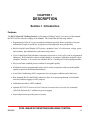

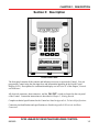

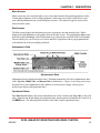
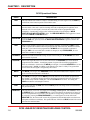
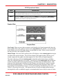
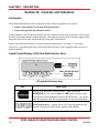


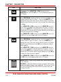
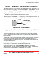
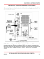

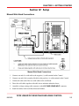
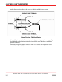
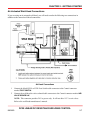


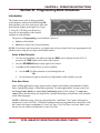
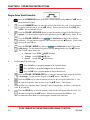
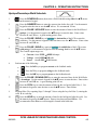

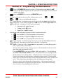


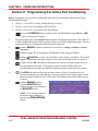


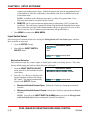
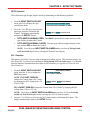
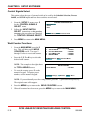


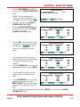
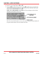

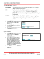

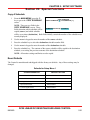
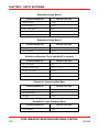
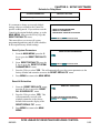


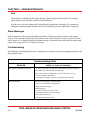
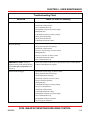
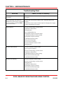

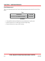
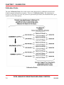
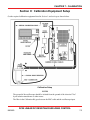

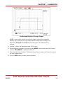


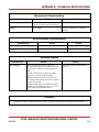

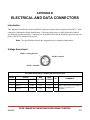
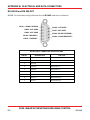

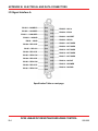
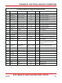

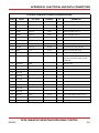
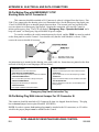


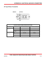


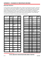


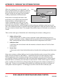
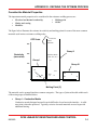

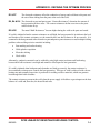
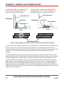


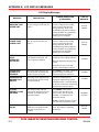


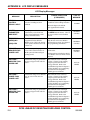


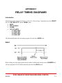

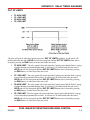


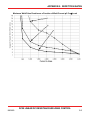


![UB25 Cover+Front Matter [Rev C] -- 1-02](http://vs1.manualzilla.com/store/data/005906297_1-9ba350e3ad2195c1d2103c91c2552cc1-150x150.png)