1
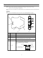
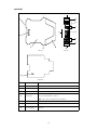
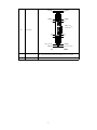
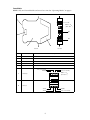
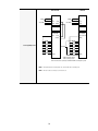
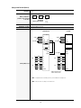
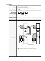
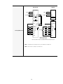
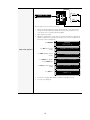
ALPHA Discrete Input Interface
Operating Instructions
Introduction
The ALPHA Discrete Input Interface allows messages to be displayed on standard ALPHA electronic signs
by using simple on/off contacts to trigger messages that have been stored in a sign. The ALPHA Discrete Input
Interface is designed for low-voltage applications.
Messages to be displayed are stored in a sign using either:
• Infrared handheld remote control
• Adaptive software such as ALPHA Messaging software (see “Creating messages using ALPHA
Messaging software” on page 23)
The ALPHA Discrete Input Interface consists of three types of modules which can be connected in any
order:
•
•
•
CPU Module — serves as an interface between the Input Modules and ALPHA signs
Input Module (up to four can be used, depending on the Operating Mode used) — the eight, dry
contact inputs of each Input Module can be configured to one of five possible Operating Modes (see
“Operating Modes” on page 9):
— Mode Ø: Discrete Fixed
— Mode 1: Momentary Triggered
— Mode 2: Binary Coded Decimal (BCD)
— Mode 3: Binary
— Mode 4: Counter
Power Module — supplies power to the CPU Module and Input Modules
Input Modules
(up to four, depending on Operating Mode
used. See “Operating Modes” on page 9.)
CPU Module
Power Module
L1
L2
PWR
(RS 232/485)
DIN rail
(If conductive, the rail
should be connected
to earth GND because
the rail serves as the
chassis GND for all
the modules.)
Sinking (NPN)
Sinking (NPN)
Sinking (NPN)
POWER
Int. Ext.
POWER
Int. Ext.
POWER
Int. Ext.
POWER
Int. Ext.
5V
24V
5V
24V
5V
24V
5V
24V
I7
I3
I7
I3
I7
I3
I7
I3
I6
I2
I6
I2
I6
I2
I6
I2
I5
I1
I5
I1
I5
I1
I5
I1
I4
I0
I4
I0
I4
I0
I4
I0
DISPLAY
SERIAL COM
(RS 232)
End clamp
Use end clamps to hold
the modules in place.
Sinking (NPN)
INPUT
STATUS
INPUT
STATUS
INPUT
STATUS
INPUT
STATUS
Sinking (NPN)
Sinking (NPN)
Sinking (NPN)
Sinking (NPN)
NOTE: Modules should be mounted in an appropriate NEMA enclosure to
ensure isolation from noise and protection from harsh environments.
Revision date: 2/3/2000
© 2000 Adaptive
1 Micro Systems
The distinctive appearance of this product is a Trade Dress of Adaptive Micro Systems, Inc.
9711-Ø7Ø1A
Related documentation
Title
Part #
Description
Network Configurations
97Ø8-8Ø46
Detailed information on how to network ALPHA signs.
ALPHA Remote Control Programming Manual
97Ø4-ØØØ2
Examples of how to program messages into ALPHA signs using a handheld
infrared remote control.
ALPHA Messaging Software User Manual v1.Ø
97Ø1-Ø2Ø2
Instructions on using the ALPHA Messaging software to program messages
into ALPHA signs.
Technical specifications
All Modules
Dimensions:
2.75"W x 4.25"H x 1"D
Weight:
4 oz per module
Operating temperature:
60°C
Humidity range:
10 – 95% non-condensing
Mounting:
DIN rail 35 x 7 mm
Power Module
AC input voltage1
Max. AC voltage: 25 Vrms
Min. AC voltage: 14 Vrms
Power consumption:
15W @ 24 Vrms
DC input voltage
Max. DC voltage: 36 VDC
Min. DC voltage: 18 VDC
Output voltage 24 VDC
Max. voltage: 36 VDC
Min. voltage: 18 VDC
Max. current: 700 mA
Bus output voltage 5 VDC
Max. voltage: 5.05 V
Min. voltage: 4.95 V
Max. current: 500 mA
Protection
Type: Polyswitch
Self-resetting: Yes
Terminals
Type: Screw
Wire size: 0, 14-2, 52 / AWG 26 - 14
CPU Module
Operating voltage: 5 V
Current draw: 150 mA
Power consumption: 0.75 W
Communications
Communication type: RS232
Serial (in): Terminal type: RJ11
Protocol: EZ95
2
Communication type: RS485
Display (out): Terminal type: RJ11
Protocol: EZ95
Communication type: RS485
Terminal type: Screw
Wire size: 0, 14-2, 52 / AWG 26 - 14
Terminals (out):
Protocol: EZ95
Max. number of drops: 32
Max. distance: 4000 ft (1200 m)
Input Module
Bus power required (5 VDC)
Max. operating voltage: 5.05 V
Min. operating voltage: 4.95 V
Max. current: 15 mA
Input power required (24 VDC)
Max. operating voltage: 36 VDC
Min. operating voltage: 18 VDC
Max. current: 90 mA
Min. current: 5 mA
Inputs per module:
8
Discrete fixed: 8
Discrete momentary: 8
BCD: 8
Binary: 7
Counter: 3 (min.)
Protection:
Polyswitch, 300 mA
Terminals:
Type: Screw
Wire size: 0, 14-2, 52 / AWG 26 - 14
Input impedance:
3600 ohms
Max. input voltage:
36 VDC
Min. input voltage:
18 VDC
Max. current draw:
3.5 mA (36 V)
Min. current draw:
4.1 mA (18 V)
1Only one power supply, 18 – 36 VDC or 24 VAC, can be used to power this
product.
Installation
1.
Determine the type of Operating Mode to be used and set the internal Input Module jumpers as required. See
“Operating Modes” on page 9.
2.
Determine the circuit type (i.e., Sinking or Sourcing) to be used and wire the circuit for the modules as
required. See “Operating Modes” on page 9.
3.
Determine the content of the messages to be displayed on the ALPHA sign(s). Then create the messages and
store them on the sign(s). See “Creating messages using ALPHA Messaging software” on page 23.
3
Module descriptions
NOTE: Always remove power from a module before changing wiring or jumper settings.
Failure to do so may damage the equipment.
NOTE: Parts are not serviceable on any of the modules. In case of malfunction, return to the manufacturer.
CPU Module
NOTE: Only one CPU Module can be used at a time. See “Operating Modes” on page 9.
B
B
E
F
G
L1
L2
PWR
(RS 232/485)
H
DISPLAY
D
SERIAL COM
(RS 232)
D
I
J
C
A
B
B
Side view
Item
Front view
Name
Description
A
Module Top
The internal PCB is attached to the Module Top.
B
Release Button
Depress each Release Button to remove the Module Bottom.
C
Module Bottom
Can be removed to expose internal PCB.
D
Intermodule Connector
Used to pass power and signals between modules. When attached to a conductive DIN rail, the
rail serves as the CHASSIS GND for all modules connected to the DIN rail.
E
DIN rail latch
Used to attach the module to a DIN EN 5Ø Ø22 mounting rail.
Serial Output
Shielded RS485 output to one or more ALPHA signs.
Because of the signal protection afforded by shielding, this is the recommended
way of connecting ALPHA signs to the CPU Module.
To connect ALPHA signs, see “Creating messages using ALPHA Messaging software” on
page 23.
(–) RS485
SHLD (Shield)
(+) RS485
GND
F
AWG 26 – 14
( Ø.14 – Ø.25 ❏ )
For shielded RS485 output, use SHLD
with (–) RS485 and (+) RS485.
L1
L2
PWR
(R
4
G
H
CPU Status Indicators
DISPLAY
PWR — When lit, this indicates the unit is powered.
L1 — Lit during power up until the CPU Module initializes.
If indicator on continuously after power up, this indicates that the power source is not sufficient.
If indicator flashing continuously, this indicates one of four possible conditions:
• no Input Module is connected
• too many Input Modules are attached for the current Operating Mode
• Input Modules are set to different Operating Modes
• an Input Module has failed or a communication failure to an Input Module has
occurred
If indicator flashes once, this means that the binary input is greater than or equal to 80 or that
count is either < -2,147,483,647 or > +2,147,483,647.
L2 — During power up, L1 and L2 flash together X+1 times, where X = Mode number (Ø - 4).
During normal operation, L2 flashes when the CPU Module is processing an input event.
Unshielded RS485 output to a single ALPHA sign. Used to:
• program messages into a sign
• trigger messages already in a sign
This is not a telephone connector.
I
SERIAL COM
RS232 input from a PC. Used to program messages and send them to a CPU Module that is up to
5Ø feet from the PC.
This is not a telephone connector.
J
Serial Input
Unused.
5
Input Module
B
B
F
Sinking (NPN)
G
H
POWER
Int. Ext.
J
5V
24V
I7
I3
I6
I2
I5
I1
I4
I0
E
I
E
INPUT
STATUS
H
Sinking (NPN)
C
A
B
Side view
G
B
Front view
A2
A1
A0
D
Internal view
Item
Name
Description
A
Module Top
The internal PCB is attached to the Module Top.
B
Release Button
Depress each Release Button to remove the Module Bottom.
C
Module Bottom
Can be removed to change jumpers on the internal PCB.
D
Internal Jumpers
The AØ, A1, and A2 internal jumpers are used to set the Operating Mode and Input Module
Address. (See “Operating Modes” on page 9.)
NOTE: Spare jumpers are included inside each Input Module.
E
Intermodule Connector
Used to pass power and signals between modules.
F
DIN rail latch
Used to attach the module to a DIN EN 5Ø Ø22 mounting rail.
G
Type of Input Module
Input Modules are configured for either Sinking (NPN) or Sourcing (PNP) current
applications.
6
COM (ØV)
I6
COM (ØV)
I7
Sinking (NPN)
COM(ØV)
I4
COM(ØV)
I5
POWER
Int. Ext.
H
Input Terminals
5V
24V
I7
I3
I6
I2
I5
I1
I4
I0
AWG 26 – 14
( Ø.14 – Ø.25 ❏ )
INPUT
STATUS
I3
I2
IØ
I1
Sinking (NPN)
+24V (+18 - 36V)
COM (ØV)
IN
COM (ØV)
+24 V (+ 18 - 36 V)
IN/OUT
I
Power Indicators
Int. — When lit, this indicates that a power source is present.
Ext. — When lit, this indicates that an external 24 VDC power source is present.
J
Input Status Indicators
When lit, this indicates activity from an input (IØ – I7).
7
Power Module
NOTE: Only one Power Module can be used at a time. See “Operating Modes” on page 9.
B
B
E
F
AWG 26 – 14
( Ø.14 – Ø.25 ❏ )
D
D
G
C
A
B
B
Side view
Item
Front view
Name
Description
A
Module Top
The internal PCB is attached to the Module Top.
B
Release Button
Depress each Release Button to remove the Module Bottom.
C
Module Bottom
Can be removed to expose the internal PCB.
D
Intermodule Connector
Used to pass power and signals between modules.
E
DIN rail latch
Used to attach the module to a DIN EN 5Ø Ø22 mounting rail.
+24 V (+ 18 - 36 VDC)
NEG (ØV)
F
Power Output
G
Power Input
NEG (ØV)
+24V (+ 18 - 36 VDC)
AWG 26 – 14
( Ø.14 – Ø.25 ❏ )
~ 24 VAC
~ 24 VAC
8
NEG (ØV)
+24 V (+ 18 - 36 VDC)
Operating Modes
NOTE: Only one Operating Mode can be used at a time. For example, if three Input Modules were
connected together, all three modules would have to use the same Operating Mode.
Discrete Fixed (Mode Ø)
Description:
When an input (IØ - I7) is high, the associated sign message is displayed. It is possible to have several messages
running simultaneously on a sign.
Minimum configuration
Power
Module
Module configuration:
(modules can be connected
in any order)
+
CPU
Module
+
Maximum no. of inputs:
+
AØ = Ø
A1 = Ø
A2 = Ø
Input Module
internal jumper settings:
Maximum no. of messages:
Input
Module
+
Input
Module
AØ = 1
A1 = Ø
A2 = 1
Input
Module
+
AØ = Ø
A1 = 1
A2 = 1
Input
Module
AØ = 1
A1 = 1
A2 = 1
32
32 (8 inputs per module x 4 Input Modules connected)
NON-ISOLATED
ISOLATED
Power Module
Power Module
~24
~24
24 VAC ~
24 VAC ~
~24
~24
OR
+18-36 VDC
OR
+
24 VDC
24 VDC
NEG(ØV)
NEG(ØV)
+18-36 VDC
24 VDC
+
NEG(ØV)
CPU Module
CPU Module
Input Module
Input Module
Sinking (NPN)
Sinking (NPN)
24 VDC
+18-36 VDC
+
COM(ØV)
Sinking (NPN) circuit:
24 VDC
COM(ØV)
I7
I7
I6
I6
I5
I5
I4
I4
I3
I3
I2
I2
I1
I1
IØ
IØ
COM(ØV)
COM(ØV)
COM(ØV) is internally connected.
24 VDC is internally connected.
NOTE: All Input Modules are internally fused. Also, the Power Module is internally fused.
NOTE: Wire the modules according to local electrical code.
9
NON-ISOLATED
ISOLATED
Power Module
Power Module
~24
~24
24 VAC ~
24 VAC ~
~24
~24
OR
+18-36 VDC
OR
24 VDC
+
24 VDC
+18-36 VDC
NEG(ØV)
+
NEG(ØV)
CPU Module
CPU Module
Input Module
Input Module
Sourcing (PNP)
Sourcing (PNP)
24 VDC
24 VDC
24 VDC (see NOTE 1)
COM(ØV)
COM(ØV)
I7
I7
I6
I6
I5
Sourcing (PNP) circuit:
24 VDC
NEG(ØV)
I4
I5
+18-36 VDC
+
I4
I3
I3
I2
I2
I1
I1
IØ
IØ
COM(ØV)
COM(ØV)
COM(ØV) is internally connected.
24 VDC is internally connected.
NOTE 1: This connection is only necessary to light the 24 VDC LED to show that power is present.
NOTE: All Input Modules are internally fused. Also, the Power Module is internally fused.
NOTE: Wire the modules according to local electrical code.
10
Momentary Triggered (Mode 1)
Description:
When an input (IØ - I7) goes to a high state (i.e., rising edge), the associated sign message is displayed until a new
message is triggered.
Minimum configuration
Power
Module
Module configuration:
(modules can be connected
in any order)
+
CPU
Module
+
Maximum no. of inputs:
+
AØ = 1
A1 = Ø
A2 = Ø
Input Module
internal jumper settings:
Maximum no. of messages:
Input
Module
+
Input
Module
AØ = 1
A1 = Ø
A2 = 1
Input
Module
+
AØ = Ø
A1 = 1
A2 = 1
Input
Module
AØ = 1
A1 = 1
A2 = 1
32
32 (8 inputs per module x 4 Input Modules connected)
NON-ISOLATED
ISOLATED
Power Module
Power Module
~24
~24
24 VAC ~
24 VAC ~
~24
~24
OR
+18-36 VDC
OR
+
24 VDC
24 VDC
NEG(ØV)
NEG(ØV)
+18-36 VDC
24 VDC
+
NEG(ØV)
CPU Module
CPU Module
Input Module
Input Module
Sinking (NPN)
Sinking (NPN)
24 VDC
+18-36 VDC
+
COM(ØV)
COM(ØV)
Sinking (NPN) circuit:
24 VDC
I7
I7
I6
I6
I5
I5
I4
I4
I3
I3
I2
I2
I1
I1
IØ
IØ
COM(ØV)
COM(ØV)
COM(ØV) is internally connected.
24 VDC is internally connected.
NOTE: All Input Modules are internally fused. Also, the Power Module is internally fused.
NOTE: Wire the modules according to local electrical code.
11
NON-ISOLATED
ISOLATED
Power Module
Power Module
~24
~24
24 VAC ~
24 VAC ~
~24
~24
OR
+18-36 VDC
OR
24 VDC
+
24 VDC
+18-36 VDC
NEG(ØV)
+
NEG(ØV)
CPU Module
CPU Module
Input Module
Input Module
Sourcing (PNP)
Sourcing (PNP)
24 VDC
24 VDC
24 VDC (see NOTE 1)
COM(ØV)
COM(ØV)
I7
I7
I6
I6
I5
I4
Sourcing (PNP) circuit:
24 VDC
NEG(ØV)
I5
+18-36 VDC
+
I4
I3
I3
I2
I2
I1
I1
IØ
IØ
COM(ØV)
COM(ØV)
COM(ØV) is internally connected.
24 VDC is internally connected.
NOTE 1: This connection is only necessary to light the 24 VDC LED to show that power is present.
NOTE: All Input Modules are internally fused. Also, the Power Module is internally fused.
NOTE: Wire the modules according to local electrical code.
12
Binary Coded Decimal (Mode 2)
Description:
The BCD value read at the inputs (IØ – I7) determines the message to run (see “For BCD and Binary modes . . .” on
page 21).
Power
Module
Module configuration:
(modules can be connected
in any order)
Maximum no. of messages:
Maximum no. of inputs:
+
CPU
Module
+
Input
Module
AØ = Ø
A1 = 1
A2 = Ø
Input Module
internal jumper settings:
8Ø
8 (with 1 Input Module connected)
NON-ISOLATED
ISOLATED
Power Module
Power Module
~24
~24
24 VAC ~
24 VAC ~
~24
~24
OR
+18-36 VDC
OR
24 VDC
+
24 VDC
+18-36 VDC
NEG(ØV)
24 VDC
+
NEG(ØV)
NEG(ØV)
CPU Module
CPU Module
Input Module
Input Module
Sinking (NPN)
Sinking (NPN)
24 VDC
+18-36 VDC
+
COM(ØV)
3
22
2
1
I5
2
Ø
I7
2
I7
I6
22
I6
2
1
I5
I4
2
Ø
I4
23
I3
23
I3
22
I2
22
I2
2
1
I1
2
1
I1
2
Ø
IØ
2
Ø
IØ
MSD
LSD
COM(ØV)
3
2
Sinking (NPN) circuit:
24 VDC
MSD
LSD
COM(ØV)
COM(ØV)
COM(ØV) is internally connected.
24 VDC is internally connected.
NOTE: All Input Modules are internally fused. Also, the Power Module is internally fused.
NOTE: Wire the modules according to local electrical code.
13
NON-ISOLATED
ISOLATED
Power Module
Power Module
~24
~24
24 VAC ~
24 VAC ~
~24
~24
OR
+18-36 VDC
OR
24 VDC
+
24 VDC
+18-36 VDC
NEG(ØV)
+
NEG(ØV)
CPU Module
CPU Module
Input Module
Input Module
Sourcing (PNP)
Sourcing (PNP)
24 VDC
24 VDC
24 VDC (see NOTE 1)
2
3
I7
2
2
I6
2
1
I5
2Ø
I4
COM(ØV)
MSD
MSD
COM(ØV)
+18-36 VDC
I7
2
2
I6
2
1
I5
2Ø
I4
+
3
I3
2
3
I3
I2
22
I2
21
I1
21
I1
2Ø
IØ
2Ø
IØ
LSD
LSD
2
3
22
2
Sourcing (PNP) circuit:
24 VDC
NEG(ØV)
COM(ØV)
COM(ØV)
COM(ØV) is internally connected.
24 VDC is internally connected.
NOTE 1: This connection is only necessary to light the 24 VDC LED to show that power is present.
NOTE: All Input Modules are internally fused. Also, the Power Module is internally fused.
NOTE: Wire the modules according to local electrical code.
14
Binary (Mode 3)
Description:
The Binary value read at the inputs (IØ – I7) determines the messages to run (see “For BCD and Binary modes . . .”
on page 21).
Power
Module
Module configuration:
(modules can be connected
in any order)
Maximum no. of messages:
Maximum no. of inputs:
+
CPU
Module
+
Input
Module
AØ = 1
A1 = 1
A2 = Ø
Input Module
internal jumper settings:
8Ø
8 (with 1 Input Module connected)
NON-ISOLATED
ISOLATED
Power Module
Power Module
~24
~24
24 VAC ~
24 VAC ~
~24
~24
OR
+18-36 VDC
OR
+
24 VDC
24 VDC
NEG(ØV)
NEG(ØV)
+18-36 VDC
24 VDC
+
NEG(ØV)
CPU Module
CPU Module
Input Module
Input Module
Sinking (NPN)
Sinking (NPN)
24 VDC
+18-36 VDC
+
COM(ØV)
COM(ØV)
I7
I7
Sinking (NPN) circuit:
24 VDC
26
I6
26
I6
2
5
I5
2
5
I5
2
4
I4
2
4
I4
2
3
I3
2
3
I3
2
2
I2
2
2
I2
2
1
I1
2
1
I1
2Ø
IØ
2Ø
IØ
COM(ØV)
COM(ØV)
COM(ØV) is internally connected.
24 VDC is internally connected.
NOTE: All Input Modules are internally fused. Also, the Power Module is internally fused.
NOTE: Wire the modules according to local electrical code.
15
NON-ISOLATED
ISOLATED
Power Module
Power Module
~24
~24
24 VAC ~
24 VAC ~
~24
~24
OR
+18-36 VDC
OR
24 VDC
+
24 VDC
+18-36 VDC
NEG(ØV)
+
NEG(ØV)
CPU Module
CPU Module
Input Module
Input Module
Sourcing (PNP)
Sourcing (PNP)
24 VDC
24 VDC
24 VDC (see NOTE 1)
COM(ØV)
COM(ØV)
I7
I7
Sourcing (PNP) sample:
24 VDC
NEG(ØV)
2
6
I6
26
I6
2
5
I5
2
5
I5
24
I4
24
I4
23
I3
23
I3
22
I2
22
I2
21
I1
21
I1
2Ø
IØ
2Ø
IØ
+18-36 VDC
+
COM(ØV)
COM(ØV)
COM(ØV) is internally connected.
24 VDC is internally connected.
NOTE 1: This connection is only necessary to light the 24 VDC LED to show that power is present.
NOTE: All Input Modules are internally fused. Also, the Power Module is internally fused.
NOTE: Wire the modules according to local electrical code.
16
Counter (Mode 4)
Description:
Module configuration:
(modules can be connected
in any order)
Maximum no. of messages:
Maximum no. of inputs:
This mode refreshes the sign’s String file “1” each time a command is processed, using the following configuration:
IØ: +/– 1I5: Store current value in the CPU Module
I1: +/– 1ØI6: Recall stored value from the CPU Module
I2: +/– 1ØØI7: Positive/Negative number (Pos. if high, Neg. if low).
I3: +/– 1ØØØMax. pos. value = +2,147,483,647. Max. neg. value = –2,147,483,647
I4: +/– 1ØØØØ
Power
Module
+
CPU
Module
+
Input
Module
AØ = Ø
A1 = Ø
A2 = 1
Input Module
internal jumper settings:
1 (the “A” message file). This message should be programmed using a handheld remote control, and
not the ALPHA Messaging software.
8 (with 1 Input Module connected)
NON-ISOLATED
ISOLATED
Power Module
Power Module
~24
~24
24 VAC ~
24 VAC ~
~24
~24
OR
+18-36 VDC
OR
+
24 VDC
24 VDC
NEG(ØV)
NEG(ØV)
+18-36 VDC
24 VDC
+
NEG(ØV)
CPU Module
CPU Module
Input Module
Input Module
Sinking (NPN)
Sinking (NPN)
24 VDC
+18-36 VDC
+
COM(ØV)
Sinking (NPN) circuit:
24 VDC
COM(ØV)
I7 POS/NEG
I7 POS/NEG
I6 RECALL VALUE
I6 RECALL VALUE
I5 STORE VALUE
I5 STORE VALUE
I4 ± 1Ø,ØØØ
I4 ± 1Ø,ØØØ
I3 ± 1,ØØØ
I3 ± 1,ØØØ
I2 ± 1ØØ
I2 ± 1ØØ
I1 ± 1Ø
I1 ± 1Ø
IØ ± 1
IØ ± 1
COM(ØV)
COM(ØV)
COM(ØV) is internally connected.
24 VDC is internally connected.
NOTE: All Input Modules are internally fused. Also, the Power Module is internally fused.
NOTE: Wire the modules according to local electrical code.
17
NON-ISOLATED
ISOLATED
Power Module
Power Module
~24
~24
24 VAC ~
24 VAC ~
~24
~24
OR
+18-36 VDC
OR
24 VDC
+
24 VDC
+18-36 VDC
NEG(ØV)
+
NEG(ØV)
NEG(ØV)
CPU Module
CPU Module
Input Module
Input Module
Sourcing (PNP)
Sourcing (PNP)
24 VDC
24 VDC
24 VDC (see NOTE 1)
COM(ØV)
COM(ØV)
I7 POS/NEG
I7 POS/NEG
I6 RECALL VALUE
I6 RECALL VALUE
I5 STORE VALUE
I4 ± 1Ø,ØØØ
Sourcing (PNP) circuit:
24 VDC
I5 STORE VALUE
+18-36 VDC
+
I4 ± 1Ø,ØØØ
I3 ± 1,ØØØ
I3 ± 1,ØØØ
I2 ± 1ØØ
I2 ± 1ØØ
I1 ± 1Ø
I1 ± 1Ø
IØ ± 1
IØ ± 1
COM(ØV)
COM(ØV)
COM(ØV) is internally connected.
24 VDC is internally connected.
NOTE 1: This connection is only necessary to light the 24 VDC LED to show that power is present.
NOTE: All Input Modules are internally fused. Also, the Power Module is internally fused.
NOTE: Wire the modules according to local electrical code.
18
L1
L2
PWR
(RS 232/485)
COUNT = 103
COUNT
1
RESET
2
POWER
Int. Ext.
5V
24V
I7
I3
I6
I2
I5
I1
I4
I0
DISPLAY
SERIAL COM
(RS 232)
INPUT
STATUS
Here is an example of how to use the above counter circuit:
1.
Initiate Counter mode by triggering I5 and I6 at the same time for at least 5 seconds. This clears ALL
messages from the signs networked to the Input Module and creates an “A” message file for use as a
counter. This also stores a counter value of Ø in the CPU Module.
2.
Wait 1 minute before proceeding.
3.
(Optional) Use a handheld remote control to edit the “A” message file. For example, if you wanted the text
“COUNT =” to appear before the counter value (as shown above), use a remote control to add this text:. (A
two-line sign is used as an example below.)
PROGRAM
TEXT FILE A
Press PROGRAM:
Sample counter application:
Press ADV until the text stops
scrolling:
A]
Press BACK until [RED] is at the end
of the line:
A]
Press INSERT. Type: COUNT =.
Then press INSERT again.
A]
Press ADV again until the text stops
scrolling:
A]
Press RUN twice:
[HLD][NHL][SS7][RED][STR]1
[HLD][NHL][SS7][RED]
[HLD][NHL][SS7][RED]COUNT
[NHL][SS7][RED]COUNT
=
[STR]1
COUNT = 0
4.
To increase the count, trigger IØ, and COUNT = 1, COUNT = 2, etc will appear on the sign.
5.
To reset the count to Ø, trigger I6.
19
=
Message numbering
For Discrete Fixed and Momentary Triggered modes . . .
IR Remote
Discrete Fixed
Message
Number
(decimal)
(Mode Ø)
“1” = closed contact
I7
I6
I5
I4
I3
I2
I1
IØ
Momentary Triggered
(Mode 1)
“1” = rising edge pulse
I7
I6
I5
I4
I3
I2
I1
IØ
“A”
1
Ø
No input = message “A” displayed on sign
Message “A” will be displayed until another
message is triggered.
Then message “A” will not appear again.
“B”
2
1
1
1
2
4
3
“E”
5
4
“F”
6
5
“G”
7
6
“H”
8
7
1Ø
12
11
“M”
13
12
“N”
14
13
“O”
15
14
“P”
16
15
“Q”
17
16
“R”
18
17
“S”
19
18
“T”
2Ø
19
“U”
21
2Ø
“V”
22
21
“W”
23
22
“X”
24
23
“Y”
25
24
“Z”
26
25
“a”
27
26
“b”
28
27
“c”
29
28
“d”
3Ø
29
“e”
31
3Ø
“f”
32
31
“g”
33
32
1
1
1
1
1
1
1
1
1
1
1
1
1
1
1
1
1
1
1
1
1
1
1
1
1
1
1
1
1
1
1
1
1
1
1
1
1
1
1
1
1
1
1
1
1
1
1
1
1
1
20
Fourth Module
11
“L”
1
Third Module
“K”
1
1
Second Module
9
1
1
1
Fourth Module
8
1
1
Third Module
9
1Ø
1
1
Second Module
“I”
“J”
1
1
First Module
3
First Module
“C”
“D”
Input Modules
Message
Number
(decimal)
Operating Mode
CPU
Module
Input Modules
Message
File Letter
ALPHA
Messaging
Software
For BCD and Binary modes . . .
Operating Mode
Message
Number
(decimal)
“A”
1
CPU
Module
Message
Number
(decimal)
Ø
“B”
2
1
“C”
3
2
“D”
4
3
“E”
5
4
BCD
Binary
(Mode 2)
(Mode 3)
1Ø’s digit
1’s digit
8
4
2
1
8
4
2
1
128
64
32
16
8
4
2
1
I7
I6
I5
I4
I3
I2
I1
IØ
I7
I6
I5
I4
I3
I2
I1
IØ
No input = message “A” displayed on sign
1
1
5
1
7
6
1
1
“H”
8
7
1
1
“I”
9
8
1
“J”
1Ø
9
1
“K”
11
1Ø
1
1
1
11
1
12
1
“N”
14
13
1
“O”
15
14
1
1
“P”
16
15
1
1
1
1
1
1
1
“Q”
17
16
1
1
1
18
17
1
1
1
“S”
19
18
1
1
1
1
21
1
23
22
1
1
“X”
24
23
1
1
“Y”
25
24
1
1
“Z”
26
25
1
1
“a”
27
26
1
1
1
1
1
1
1
1
1
1
1
1
1
3Ø
29
1
31
3Ø
1
1
1
“f”
32
31
1
1
“g”
33
32
1
1
1
“h”
34
33
1
1
1
“i”
35
34
1
1
1
1
1
1
1
1
1
1
1
1
1
1
1
1
1
36
35
1
1
1
36
1
1
1
1
1
1
“l”
38
37
1
1
39
38
1
1
1
“n”
4Ø
39
1
1
1
“o”
41
4Ø
1
“p”
42
41
1
“q”
43
42
1
1
1
1
1
1
1
1
1
1
1
1
1
1
1
1
1
1
1
1
1
1
1
1
1
1
1
1
1
1
1
1
1
1
1
1
1
1
1
1
1
1
1
1
1
1
1
1
1
1
1
1
37
1
1
1
1
“j”
1
1
1
1
“k”
1
1
1
1
“d”
1
1
1
1
“e”
21
1
1
1
“m”
1
1
1
1
22
27
1
1
1
“V”
28
1
1
1
“W”
28
1
1
1
1
29
1
1
1
“R”
“c”
1
1
12
“b”
1
1
1
1
13
19
1
1
“L”
2Ø
1
1
“M”
21
1
1
6
2Ø
1
1
1
“F”
“T”
No input = message “A” displayed on sign
1
“G”
“U”
LSB
Message File
Letter
ALPHA
Messaging
Software
MSB
IR Remote
(up to 76
messages
can be
programmed)
1
1
1
1
1
Operating Mode
Message
Number
(decimal)
CPU
Module
Message
Number
(decimal)
BCD
Binary
(Mode 2)
(Mode 3)
1Ø’s digit
1’s digit
8
4
2
1
8
4
2
1
128
64
32
16
8
4
2
1
I7
I6
I5
I4
I3
I2
I1
IØ
I7
I6
I5
I4
I3
I2
I1
IØ
1
1
1
1
“r”
44
43
1
“s”
45
44
1
“t”
46
45
1
1
“u”
47
46
1
1
1
1
1
“v”
48
47
1
“w”
49
48
1
“x”
5Ø
49
1
“y”
51
5Ø
1
1
1
1
1
52
51
1
1
53
52
1
1
“2”
54
53
1
1
“3”
55
54
1
1
1
1
1
1
“4”
56
55
1
1
1
“5”
57
56
1
1
1
1
1
1
“6”
58
57
1
1
59
58
1
1
1
1
1
“8”
6Ø
59
1
“9”
61
6Ø
1
“+”
62
61
1
1
“-”
63
62
1
1
1
1
“7”
1
1
1
1
“*”
64
63
1
1
“/”
65
64
1
1
1
1
1
66
65
1
1
1
67
66
1
1
1
1
1
1
68
67
1
1
69
68
1
1
“)” 1
7Ø
69
1
1
“!”
71
7Ø
1
1
1
1
1
1
1
1
1
1
1
1
1
1
1
1
1
1
1
1
1
1
1
1
1
1
1
1
1
1
1
1
1
1
1
1
1
1
1
1
1
1
1
1
1
1
1
1
1
1
1
1
1
1
1
1
1
1
1
1
1
1
1
1
1
1
1
1
1
1
1
1
1
1
1
1
1
1
1
1
1
1
1
1
1
1
1
1
1
“#”
72
71
1
1
1
“&”
73
72
1
1
1
1
“%”
74
73
1
1
1
1
“$”
75
74
1
1
1
1
“;”
76
75
1
1
1
1
“:”
77
76
1
1
1
1
1
“.”
78
77
1
1
1
1
1
1
79
78
1
1
1
1
“]”1
8Ø
79
1
1
1
1
22
1
1
1
1 This message cannot be programmed using an IR Remote Control.
1
1
“=”
“>”
1
1
“<“
“(“ 1
1
1
1
“z”
1
1
1
“1”
“[“
LSB
Message File
Letter
ALPHA
Messaging
Software
MSB
IR Remote
(up to 76
messages
can be
programmed)
1
1
1
1
1
1
1
1
1
1
1
1
1
1
1
1
1
1
1
1
1
1
1
1
1
1
1
1
1
1
1
1
1
1
1
1
1
1
1
1
1
1
1
1
1
Creating messages using ALPHA Messaging software
NOTE: If one or more Input Modules are connected to the CPU Module, you may want to temporarily
disconnect the CPU Module from the Input Modules. Otherwise, signals coming into the Input
Modules may interfere with downloading messages from the ALPHA Messaging software.
1.
Connect a PC to the CPU Module:
L1
L2
PWR
* 25-foot RS232 cable
(1Ø88-8625)
or
5Ø-foot RS232 cable
(1Ø88-8627)
(RS 232/485)
To a serial
COM port
DISPLAY
SERIAL COM
(RS 232)
RJ11-to-DB25 adapter
(437Ø-ØØØ1C)
or
* RJ11-to-DB9 adapter
(1Ø88-91Ø8)
* Included with the ALPHA Messaging software
2.
Create messages using the ALPHA Messaging software.
3.
Network one or more ALPHA signs to the CPU Module (below). Then store the messages in the signs using
ALPHA Messaging software.
Networking a single sign (unshielded)
1-foot RS485 cable
(1Ø88-8636)
or
8-foot RS485 cable
(1Ø88-8624)
L1
L2
PWR
(RS 232/485)
DISPLAY
SERIAL COM
(RS 232)
Maximum = 8 feet
23
L1
L2
PWR
(RS 232/485)
DISPLAY
SERIAL COM
(RS 232)
NOTE: When signs are
networked to the
CPU Module, all the
signs must be the
same model when
ALPHA Messaging
software is used.
1-foot RS485 cable
(1Ø88-8636)
or
8-foot RS485 cable
(1Ø88-8624)
To next
sign
Modular
Network
Adapter
(4331-Ø6Ø2)
Maximum = 4ØØØ feet (@ 96ØØ baud)
24
+ RS485 (Black)
SHLD
RS485 cable
(1Ø88-8ØØØ)
– RS485 (Red)
GN
– RS485 (Red)
YL
RD
SHLD
BR
BK
• Connect RED wire from RS485 cable to YL screw.
• Connect BLACK wire from RS485 cable to BK screw.
• Connect SHIELD wire from RS485 cable to RD screw if the sign is a
Series 4ØØØ or Series 7ØØØ. Otherwise, connect the two SHIELD wires
to each other, but not to the RD screw.
+ RS485 (Black)
WH
BL
OR
Networking one or more signs (shielded)