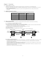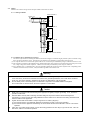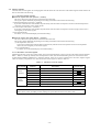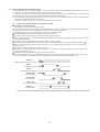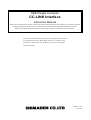
1
SR83 Digital Controller CC-LINK Interface Instruction Manual Thank you for purchasing our product. Please check that the delivered product is the actual item you ordered. Please do not begin operating this product until you read this instruction manual thoroughly and understand its contents. Please ensure that this instruction manual is made easily accessible to the final user of the instrument. This instruction manual describes the CC-Link communication interface, an optional function of the SR83 digital controller. For details on the performance and parameters of the SR83, please refer to the separate instruction manual. SR80CC-1AE July 2001 Safety Rules (Read the following information before you begin to use the apparatus.) In using this product, please be very careful and observe safety by handling the instrument properly. Only operate this product by following the instructions presented in this instruction manual and in the related manuals referred to herein. The safety rules are limited to those that are directly related to the operation of this product. For safety rules concerning the product as a sequencer system, please refer to the user's manual for the CPU unit made by Mitsubishi Electric Corporation. The safety rules are divided between "warnings" and "cautions" reflecting the seriousness of the notice in question. Warning This heading indicates that improper handling could create a hazardous situation that could result in severe injury or even death. Caution This heading indicates that improper handling could create a hazardous situation that could result in injury or damage to the product or surroundings. Note that even those matters designated by "caution" could lead to a more serious outcome depending on the circumstances. As both headings signify a matter demanding the utmost care and attention, please pay close attention to these notices. Keep this manual at the work site to be referred to readily whenever necessary and ensure that it is always accessible by the end user. [Notes on matters concerning design] Warning ● Should the data link go out of communication, data of the master unit is retained. In a sequence program, an interlocking circuit should be formed so that the system works on the safety side by the use of communication status information. Caution ● Control lines and communication cables should not be bundled with the main power supply cable and/or power lines or installed adjacently to the latter. They should be spaced apart by more than 100 mm as a guideline. Unfamiliar noises may signify an erroneous action. -1- Contents Chapter 1 Chapter 2 Chapter 3 Chapter 4 Chapter 5 Safety Rules . . . . . . . . . . . . . . . . . . . . . . . . . . . . . . . . . . . . . . . . . . . . . . . . . . . . . . . . . . . . . . . . . . . . . . 1 Contents ......................................................................2 Outline 1.1 Outline . . . . . . . . . . . . . . . . . . . . . . . . . . . . . . . . . . . . . . . . . . . . . . . . . . . . . . . . . . . . . . . . . . . . . . 3 Specifications 2.1 General specifications . . . . . . . . . . . . . . . . . . . . . . . . . . . . . . . . . . . . . . . . . . . . . . . . . . . . . . . . . . . 3 2.2 Performance specifications . . . . . . . . . . . . . . . . . . . . . . . . . . . . . . . . . . . . . . . . . . . . . . . . . . . . . . . 3 Connection 3.1 Special cable for CC-Link. . . . . . . . . . . . . . . . . . . . . . . . . . . . . . . . . . . . . . . . . . . . . . . . . . . . . . . . 4 3.2 Maximum transmission distance . . . . . . . . . . . . . . . . . . . . . . . . . . . . . . . . . . . . . . . . . . . . . . . . . . . 4 3.3 Wiring of data link cable . . . . . . . . . . . . . . . . . . . . . . . . . . . . . . . . . . . . . . . . . . . . . . . . . . . . . . . . . 4 3.3.1 Connection of special cable for CC-Link . . . . . . . . . . . . . . . . . . . . . . . . . . . . . . . . . . . . . . 4 3.3.2 Notes on cable connection . . . . . . . . . . . . . . . . . . . . . . . . . . . . . . . . . . . . . . . . . . . . . . . . . 4 3.4 Wiring . . . . . . . . . . . . . . . . . . . . . . . . . . . . . . . . . . . . . . . . . . . . . . . . . . . . . . . . . . . . . . . . . . . . . . 5 3.4.1 Wiring for SR83 . . . . . . . . . . . . . . . . . . . . . . . . . . . . . . . . . . . . . . . . . . . . . . . . . . . . . . . . . 5 3.4.2 Matters to be attended to in wiring . . . . . . . . . . . . . . . . . . . . . . . . . . . . . . . . . . . . . . . . . . . 5 3.5 Maintenance and inspection . . . . . . . . . . . . . . . . . . . . . . . . . . . . . . . . . . . . . . . . . . . . . . . . . . . . . . 6 Setting before operation and procedure 4.1 Sequencer setting. . . . . . . . . . . . . . . . . . . . . . . . . . . . . . . . . . . . . . . . . . . . . . . . . . . . . . . . . . . . . . . 7 4.2 SR83 parameter setting . . . . . . . . . . . . . . . . . . . . . . . . . . . . . . . . . . . . . . . . . . . . . . . . . . . . . . . . . . 7 4.3 Linking to sequencer . . . . . . . . . . . . . . . . . . . . . . . . . . . . . . . . . . . . . . . . . . . . . . . . . . . . . . . . . . . . 8 4.3.1 Sequencer areas used for CC-Link . . . . . . . . . . . . . . . . . . . . . . . . . . . . . . . . . . . . . . . . . . . 8 4.3.2 Notes on sequencer programming . . . . . . . . . . . . . . . . . . . . . . . . . . . . . . . . . . . . . . . . . . . 8 4.4 Remote input and output signals . . . . . . . . . . . . . . . . . . . . . . . . . . . . . . . . . . . . . . . . . . . . . . . . . . . 9 4.4.1 Remote input and output functions . . . . . . . . . . . . . . . . . . . . . . . . . . . . . . . . . . . . . . . . . . . 9 4.4.2 List of remote input and output signals. . . . . . . . . . . . . . . . . . . . . . . . . . . . . . . . . . . . . . . 10 4.4.3 Details of remote input and output signals . . . . . . . . . . . . . . . . . . . . . . . . . . . . . . . . . . . . 11 4.5 Remote register . . . . . . . . . . . . . . . . . . . . . . . . . . . . . . . . . . . . . . . . . . . . . . . . . . . . . . . . . . . . . . . 12 4.5.1 Remote register function. . . . . . . . . . . . . . . . . . . . . . . . . . . . . . . . . . . . . . . . . . . . . . . . . . 12 4.5.2 Allocation of remote register . . . . . . . . . . . . . . . . . . . . . . . . . . . . . . . . . . . . . . . . . . . . . . 12 4.6 Extended display and extended setting . . . . . . . . . . . . . . . . . . . . . . . . . . . . . . . . . . . . . . . . . . . . . 13 4.6.1 Outline of extended display and extended setting . . . . . . . . . . . . . . . . . . . . . . . . . . . . . . 13 4.6.2 Extended display/extended setting table. . . . . . . . . . . . . . . . . . . . . . . . . . . . . . . . . . . . . . 16 Troubleshooting 5.1 Extended display/extended setting data error codes . . . . . . . . . . . . . . . . . . . . . . . . . . . . . . . . . . . 21 5.2 Lamps for CC-Link communication . . . . . . . . . . . . . . . . . . . . . . . . . . . . . . . . . . . . . . . . . . . . . . . 21 5.3 Lamps for CC-Link communication abnormality . . . . . . . . . . . . . . . . . . . . . . . . . . . . . . . . . . . . . 21 -2- Chapter 1 Outline This instruction manual describes the specifications, names of parts and setting of a CC-Link remote device, that is, the SR83, to be used in combination with a MELSEC series sequencer CPU made by Mitsubishi Electric Corporation. 1.1 Outline (1) This instruction manual describes the specifications, handling, programming method, etc., of the SR83 digital controller (hereinafter to be referred to as the SR83) for use as a remote device station of the CC-Link system. (2) The SR83 takes in thermocouple, R.T.D., voltage or current input, allows comparison with set temperature and outputs control signals to an operating device. It is also capable of reading and writing measured temperature values, output values and various parameter settings. (3) CC-Link is an abbreviation of "control and communication link" and the abbreviated form is used throughout this instruction manual. The CC-Link is a system to connect an input/output unit, an intelligent function unit, a special function unit, and the like which are installed dispersedly and allows them to be controlled from a sequencer CPU. 1) When various units of a system are installed in a dispersed configuration, wiring for the entire system can be accomplished economically. 2) ON/OFF information concerning input and output of each unit and numerical data can be received/transmitted easily and quickly. 3) When a plurality of sequencer CPU's are connected, a simple dispersed system can be constructed. 4) As it is possible to connect various devices produced by the associated manufacturer, customers' systems can be extended or modified to meet a number of requirements. Master station Sequencer CPU SR83 Chapter 2 Specifications This chapter deals with general specifications and performance specifications of the SR83 CC-Link. 2.1 General specifications For general specifications, please refer to the instruction manual of the SR80 series. 2.2 Performance specifications The SR83 performance specifications are shown in Table 2.2. Table 2.2 Performance specifications Item Specification Version of CC-Link 1.10 Communication system Broadcast polling Synchronization system Frame synchronization Type of transmission line Bus type (Following RS-485: 3-line system) Transmission speed 156K/625K/2.5M/5M/10M bps Type of station Remote device station The number of possessory stations Type of device One station Remote station numbers Temperature controller 1 ~ 64 Maximum transmission distance Transmission rate 156K 625K 2.5M 5M 10M Total distance 1200m 900m 400m 160m 100m The number of connectable units The number of stations which satisfies the following formulae (1) and (2): (1 × a)+(2 × b)+(3 × c)+(4 × d) < = 64 ... (1) a: The number of stations with 1 possessory station b: The number of stations with 2 possessory stations c: The number of stations with 3 possessory stations d: The number of stations for 4 possessory stations (16 × A)+(54 × B)+(88 × C) < = 2304 ... (2) A: The number of remote I/O stations B: The number of remote device stations C: The number of local stations Connecting cable Special cable for CC-Link Terminal resistance 110Ω -3- Chapter 3 Connection 3.1 Special cable for CC-Link (1) In the CC-Link system, a cable equivalent to the cable version 1.10 specified for CC-Link should be used. (2) For the CC-Link, use the special cable recommended in Mitsubishi Electric Corporation CC-Link Master/Local Unit User's Manual (Detailed Instructions). (3) If any other cable except the special cable for CC-Link is used, the performance of the CC-Link system will not be guaranteed. 3.2 Maximum transmission distance The following table shows the relation between transmission rate and maximum transmission distance. Transmission rate Length of cable between stations Maximum transmission distance 156Kbps 20cm or longer 1200m 625Kbps 20cm or longer 900m 2.5Mbps 20cm or longer 400m 5Mbps 20cm or longer 160m 10Mbps 20cm or longer 100m 3.3 Wiring of data link cable The wiring of special cables for CC-Link for connecting the SR83 and the master unit is described in the following. 3.3.1 Connection of special cable for CC-Link (1) The order of cable connection has nothing to do with the station numbers. (2) Concerning the units on both ends of the CC-Link, the terminal resistances provided as accessories of those units should be connected. Connect each terminal resistance across DA and DB. (3) Terminal resistances to be connected in the CC-Link system should be 110Ω 1/2W. (4) The master unit can be connected other than on both ends. (5) Avoid star connection. (6) How to connect the SR83 and the master unit via special cable for CC-Link is illustrated below. Terminal resistance Master unit side SR83 I/O unit or the like DA DA DA DB DG DB DG DB DG SLD FG Special cable for CC-Link SLD FG Special cable for CC-Link Terminal resistance SLD FG 3.3.2 Notes on cable connection (1) Concerning the special cable for CC-link, Version 1.00 and Version 1.10 should not be used together. If a Version 1.10 cable is mixed with a Version 1.00 cable in use, all cables are regarded as Version 1.00. In that case, however, normal data transmission cannot be guaranteed. Connect the shielding wire of a special cable for a CC-link to the "SLD" of each unit, pass it through "FG" and carry out the D type (the 3rd grade) or higher type grounding on both ends of it. Ensure that the D type (the 3rd grade) or higher type grounding for each FG terminal is carried out. If you fail to do so, the instrument may not operate correctly. SLD and FG are connected inside the body of the SR83. -4- 3.4 Wiring Matters to be noted in wiring and an example of SR83 connection are shown. 3.4.1 Wiring of SR83 SR83 controller 1 Master unit DA 21 DA DB 22 DB DG 23 DG SLD 24 SLD 25 FG SR83 controller 2 21 DA 22 DB 23 DG 24 SLD 25 FG SR83 controller N 21 DA 22 DB 23 DG 24 SLD 25 FG To be connected to other CC-Link devices 3.4.2 Matters to be attended to in wiring • One of the requirements for enabling the SR83 to function thoroughly to establish a highly reliable system is external wiring that is not easily affected by noise. The following are matters to be attended to in performing external wiring. (1) Use separate cables for AC and for the special cable for CC-Link to keep it unaffected by surge or induction on the AC side. (2) The external line should not be bundled with or installed adjacently with a load line except those from the main power circuit line, a high voltage line and the sequencer. Otherwise it will easily be affected by noise, surge or induction. (3) For a shielding wire or a shielded cable, one-point grounding should be carried out on the sequencer side. Depending on the condition of external noise, however, it may be better to ground on the external side. Warning ● ● The SR83 should be used in environmental conditions as stated in the general specifications in its instruction manual. If it is used in any environment other than that noted in the general specifications, this could cause an electric shock, fire, erroneous operation, damage to the product or deterioration of its functionality. Do not directly touch a conductive part or an electronic component of the SR83 while it is energized. This could create an electric shock, erroneous operation or other failure. Caution ● ● ● ● Make sure to ground the FG terminal using the D type (the 3rd grade) or higher grounding. If not, erroneous operation could result. Wire the SR83 correctly after confirming the rated voltage of the product and the terminal arrangement. Connection to a power source with voltage different from the rated one or with erroneous wiring will create a fire hazard or failure of the apparatus. Tighten the terminal screws within a torque range of M3.5 1.0N•m (10kgf•cm). (1) If a terminal screw is not sufficiently tightened, it will lead to a short or erroneous operation. (2) If a terminal screw is tightened excessively, the screw will be broken and it will lead to a short or erroneous operation. Take care not to allow foreign matter, such as the cutting powder from wire chips, to get into the unit. This can lead to fire, failure or erroneous operation. -5- 3.5 Maintenance and inspection Although there is no particular inspection item for the SR83, check the inspection items as described in the Mitsubishi Electric Corporation Sequencer CPU User's Manual so that your system can always be used under optimal conditions. Warning ● ● Do not touch a terminal while the instrument is energized. This can result in an electric shock or erroneous operation. Before cleaning or tightening a terminal screw further, make sure to externally turn off power for all phases. Without cutoff in all phases, trouble or erroneous operation of the SR83 can result. Caution ● ● ● Do not disassemble or remodel the SR83. This can lead to trouble, erroneous operation, an injury or a fire. The case of the SR83 is made of a plastic resin. It should not be allowed to fall or receive impact shock. This could result in serious damage to the SR83. Mount or remove the SR83 on/from the panel only after turning power off externally for all phases. Without cutoff in all phases, trouble or erroneous operation of the SR83 could be the result. -6- Chapter 4 Setting before operation and procedure 4.1 Sequencer setting When SR83 setting is carried out through the CC-Link, the SR83 has to be regarded as a remote device occupying one station. Accordingly, CC-Link setting should be carried out in consideration of the number of units to be connected and the number of possessory stations. 4.2 SR83 parameter setting There are three types of communication-related parameters for the SR83 as listed below and these parameters are unable to be changed through communication, that is, they should be set by key operation on the front panel. For setting, follow the procedure by referring to the key sequence shown in the instruction manual of the SR80 Series. ● Communication address (station No.) setting screen 1-30 When the SR83 sets a station No., a data area to store information on I/O signals for control and read or written data is defined. Initial value: OFF Setting range: OFF, 1 ~ 64 (Setting OFF means resetting.) ● Communication (transmission) rate setting screen 1-31 The speed of data transmission between the SR83 and the master station is set. Initial value: 156 kbps Setting range: 156k, 625k, 2.5M, 5M, 10Mbps : 156k, : 625k, : 2.5M, : 5M, : 10M ● Setting of communication mode 1-29 (1) A mode for the master station to write data by extended setting or the like is selected. (2) A communication mode should be set as an extended setting. This means that a change of setting from the local mode (LOC) to the communication mode (COM) is not possible from the front panel. Front key operation allows only the change from the communication mode (COM) to the local mode (LOC). (3) The communication mode setting enables writing in the communication mode (COM) or the local mode (LOC) by extended setting. Initial value: LOC Setting range: LOC, COM : Local mode; only extended display through CC-Link communication is effective. : Communication mode; extended display and extended setting through CC-Link communication are effective. ● Status lamp on front panel The status lamp is provided on the right-hand side of the front panel display of the SR83. This lamp lights when the CC-Link is in the status of RUN and goes out when it is not in communication. PV ˚C SV OUT1 OUT2 EV1 EV2 EV3 AT MAN SV2 SB REM STBY RUN COM RUN COM ∗ This serves as the RUN status lamp DISP AT SR83 for the CC-Link. ENT SHIMADEN -7- 4.3 Linking to sequencer (1) The SR83, as a remote device, is allocated for I/O in the relay/register area with the master unit. (2) The allocated I/O area is treated as areas divided by channel. Data are exchanged between the connected SR83 and the master unit. 4.3.1 Sequencer areas used for CC-Link SR83 data are allocated to remote input/output area and relay/register areas of the master unit. Remote I/O Input Relay Classification The number of points 32 bit Description Bit area allocated for input Classification Remote register Input Register 4 Word Input register allocated on a unit of words RWrm ~ RWrm+3 Output Relay 32 bit Bit area allocated for output Area RXn0 ~ RX(n+1)F RYn0 ~ RY(n+1)F m, n: Addresses given to master unit by the station number setting Numerical values used in the areas are hexadecimal numbers. Output Register 4 Word Output register allocated on a unit of words RWwm ~ RWwm+3 4.3.2 Notes on sequencer programming ● Procedure of requesting initial data processing This section describes the SR83 action in response to the application of power, a station number change and a communication rate change, and presents the basic timing of a request for initial data processing. 1 When power is applied or a station number or a communication rate is changed, the SR83 turns the "initial date processing request flag" RX(n+1)8 of the remote input/output ON. 2 The "initial data processing finish flag" RY(n+1)8 is turned ON by a higher order sequence. 3 Seeing the "initial data processing finish flag" RY(n+1)8, the SR83 turns the initial date processing request flag" RX(n+1)8 OFF. 4 "Remote READY" RX(n+1)B is turned ON. 5 RY(n+1)8 is turned OFF by the higher order sequence. RX(n+1)8 3 1 Initial data processing request RY(n+1)8 5 2 Initial data processing finish RX(n+1)B 4 Remote READY ● Procedure of requesting initial data setting A request for initial data setting does not cause internal processing of the SR83. Basic timing of a request for initial data setting is shown in the following. 1 The "initial data setting request flag" RY(n+1)9 is turned ON by a higher order sequence. 2 The SR83 turns the "remote READY" RX(n+1)B OFF. 3 The SR83 turns the "initial data setting finish flag" RX(n+1)9 ON. 4 Seeing the "initial data setting finish flag" RX(n+1)9, the higher order sequence turns the "initial data setting request flag" RY(n+1)9 OFF. 5 The SR83 turns the "initial data setting finish flag" RX(n+1)9 OFF. 6 The "remote READY" RX(n+1)B is turned ON. RY(n+1)9 Initial data setting request 4 1 RX(n+1)9 Initial data setting finish RX(n+1)B Remote READY 3 2 -8- 5 6 4.4 Remote input and output signals Allocation of input and output signals and the respective functions are described in the following. 4.4.1 Remote input and output functions ● Remote input (Remote → Master) The remote input area comprises the following: (1) Event 1 and 2 alarm statuses The statuses of the event 1 and 2 actions are shown. The RXnO and RXn1 bits turn ON when the event alarm is in action and the RXnO and RXn1 bits remain OFF when the event alarm is stopped or the optional event alarm function is not added. (2) Burnout status The RXn2 bit turns ON when scaleover happens at the higher or lower limit of PV or a cold point compensator goes into trouble. It remains OFF in normal action. (3) Heater break alarm The action status of the heater break alarm is shown. The RXn3 bit turns ON when the heater break alarm is in action and it remains OFF when the event alarm is stopped or the optional event alarm function is not added. (4) PID/AT The status of execution of auto-tuning is shown. The RXn4 bit turns ON when auto-tuning is in execution and it remains OFF during PID control. (5) Communication mode A communication mode is shown. The RXnA bit remains OFF in the local mode and it is ON in the communication mode. (6) Status of remote register selection The status of remote register selection is shown when a set value of temperature SV is set by using either the RWwm area or extended setting. The RXnB bit turns ON when extended setting is selected and it turns OFF upon selection of the remote register (RWwm). (7) Remote register (RWwm) error flag An error status in setting an SV value by using the RWwm is indicated. If an SV value is set in the local mode of communication, a set value is out of the setting range or auto-tuning is in execution, the RXnE bit turns ON and it turns OFF when setting is accomplished normally. (8) Input area related to extended display/extended setting A display or the like can be changed by using the RW area while "hand-shaking" with the SR83 and input flags for such hand shaking are allocated to RXnC and RXnD. For details, see 4.6 "Extended display and extended setting." (9) System area Remote input called the system area is allocated to RX(n+1)8 ~ RX(n+1)B. This is the interface area between the CC-Link supported devices and the master module. ● Remote output (Master → Remote) The remote output area comprises the following. (1) Setting numbers for extended display and extended setting In the remote register area, an item to be input or output can be changed from the user sequence by using a setting number and a hand shaking bit. Such a remote register is defined as an extended area. Input is called display and output is called setting. Areas in which a command number is written to decide for what purpose the extended area is used are secured in RYn0 ~ RYm5 and RYn6 ~ RYnB. RYnC, RXnC and RXnD are used as flag areas for such hand shaking. For details, see 4.6 "Extended display and extended setting." (2) System area Remote output called the system area is allocated to RY(n+1)8 ~ RY(n+1)A. This is the interface area between the CC-Link supported devices and the master module. -9- 4.4.2 List of remote input and output signals For data exchange with the master unit, the SR83 uses 32 input points and 32 output points. Table 4.1 shows the allocation of input and output signals and names of signals. "RX" in the device numbers indicates that they input signals from the SR83 to the master unit and "RY" indicates that they are output signals from the master unit to the SR83. For details of signals, see 4.4.3 "Details of remote input and output signals." Table 4.1 List of remote input and output signals Direction of signal: SR83 → Master unit Device No. Name of signal RXn0 Event 1 alarm status* RXn1 Event 2 alarm status* RXn2 Burnout status RXn3 Heater break alarm status* RXn4 PID/AT RXn5 RXn6 RXn7 Unused RXn8 RXn9 RXnA Communication mode status RXnB SV setting remote register selection status RXnC Extended display finish RXnD Extended setting finish RXnE Remote register (RWwm) error flag RXnF RX(n+1)0 RX(n+1)1 RX(n+1)2 RX(n+1)3 Unusable RX(n+1)4 RX(n+1)5 RX(n+1)6 RX(n+1)7 RX(n+1)8 Initial data processing request flag RX(n+1)9 Initial data setting finish flag RX(n+1)A Error status flag RX(n+1)B Remote READY RX(n+1)C RX(n+1)D Unusable RX(n+1)E RX(n+1)F n: Address given to the master unit by station number setting Direction of signal: Master unit → SR83 Name of signal Device No. RYn0 [Extension] number setting for display RYn1 RYn2 RYn3 RYn4 RYn5 RYn6 [Extension] number setting for setting RYn7 RYn8 RYn9 RYnA RYnB RYnC Extended display flag RYnD Extended setting flag RYnE Unused RYnF RY(n+1)0 RY(n+1)1 RY(n+1)2 RY(n+1)3 Unusable RY(n+1)4 RY(n+1)5 RY(n+1)6 RY(n+1)7 RY(n+1)8 Initial data processing finish flag RY(n+1)9 Initial data setting request flag RY(n+1)A Error reset request flag RY(n+1)B RY(n+1)C RY(n+1)D Unusable RY(n+1)E RY(n+1)F Turning an unused device ON and OFF, will create no problems for the SR83. In case an unusable device is turned ON and OFF in a sequence program, the proper functioning of the SR83 will not be guaranteed. * Unable to be used unless the optional function is added. - 10 - b0 b1 b2 b3 b4 b5 b0 b1 b2 b3 b4 b5 4.4.3 Details of remote input and output signals The functions of remote input and output signals are shown in table 4.2. Table 4.2 Device No. Details of remote input and output signals Description Name of signal RXn0 Event 1 alarm status * OFF: Alarm stopped ON: Alarm in action RXn1 Event 2 alarm status * OFF: Alarm stopped ON: Alarm in action RXn2 Burnout status RXn3 Heater break alarm status * RXn4 PID/AT RXnA Communication mode status OFF: Local mode, only reading is possible. ON: Communication mode, both reading and writing are possible. RXnB SV remote register selection Whether a set value of temperature is to be set by remote register (RWwm) or by extended setting is selected. 0: Remote register (RWwm) 1: Extended setting (setting No. 3) RXnC Extended display finish To turn ON upon finishing display in RWr extended area To turn OFF when extended display flag (RYnC) turns OFF. RXnD Extended setting finish To turn ON upon finish of setting in RWw extended area To turn OFF when extended setting flag (RYnD) turns off. RXnE RX(n+1)8 Remote register (RWwm) error flag Initial data processing request flag RX(n+1)9 Initial data setting finish flag RX(n+1)A Error status flag RX(n+1)B Remote READY RYn0 ~ 5 [Extension] number setting for display RYn6 ~ B [Extension] number setting for setting RYnC Extended display flag RYnD Extended setting flag RY(n+1)8 Initial data processing finish flag RY(n+1)9 Initial data setting request flag RY(n+1)A Error reset request flag OFF: Normal action ON: SCHH, SCLL, CJHH or CJLL has occurred. OFF: Alarm stopped ON: Alarm in action OFF: PID control ON: AT control To turn on in any of the following cases when writing in remote register (RWwm): • Communication local mode • Set value is out of setting range. • Auto tuning in execution Initial data processing request flag is turned ON by SR83 upon applying power or upon hardware resetting, to request initial data setting. The flag is turned OFF when initial data processing finishes (initial data processing finish flag RY(n+1)8 turning ON). In response to request for initial data setting (RY(n+1)9 ON), this flag turns ON upon finishing of initial data setting. When initial data setting request flag turns OFF upon finishing of initial data setting, initial data setting finish flag also turns OFF. SR83 turns this flag ON in case of error in extended display or extended setting. To turn ON upon applying power, upon hardware resetting or when initial data setting finishes to complete data setting and it becomes READY for remote action. This flag remains OFF while extended display or extended setting is being processed and turns ON when the processing finishes. This is used as interlock in reading from and writing in master unit. To set an item desired to be displayed in [extension] area of RWr by binary notation. To set an item desired to be set in [extension] area of RWw by binary notation When display in [extended] area of RWr is intended, this flag turns ON upon setting [extended] setting No. for display. It turns OFF upon confirmation that (RXnC) turns ON when extended display finishes. When display in [extended] area of RWr is intended, this flag turns ON upon setting [extended] setting No. for display. It turns OFF upon confirmation that (RXnD) turns ON when extended display finishes. To turn ON upon applying power, hardware resetting or finishing of initial data processing To turn ON when initial data is to be set or changed When error reset flag is turned ON, error status flag turns OFF. n: Address given to master unit by station No. setting * Unable to be used unless optional function is added. - 11 - 4.5 Remote register The SR83 has a remote register for exchanging data with the master unit. The allocation of the remote register and the structure of data are described in the following. 4.5.1 Remote register function ● Remote register area: RWr (Remote → Master) This area is used as an input area when viewed from the master unit. The register operates differently depending on the setting of the SR83 as described in the following. (1) Measured temperature value (PV): (standard) It processes communication with the SR83 asynchronously with the master unit sequence and stores measured temperature values (PV) read regularly in the remote register. (2) Control output value (OUT1): (standard) It processes communication with the SR83 asynchronously with the master unit sequence and stores output values (OUT1) read regularly in the remote register. (3) For extended display For details, see 4.6 "Extended display and extended setting." ● Remote register area: RWw (Master → Remote) This area is used as an input area when viewed from the master unit. The register operates differently depending on the setting of the SR83 as described in the following. (1) Set temperature value (SV) It processes communication with the SR83 asynchronously with the master unit sequence and writes set temperature values (SV) stored regularly in the remote register. (2) For extended setting For details, see 4.6 "Extended display and extended setting." 4.5.2 Allocation of remote register Measured temperature values (PV), output values (OUT1) and extended display values are stored in the remote register addresses RWrn ~ RWrn+3, channel by channel, while set temperature values (SV) and extended setting values are stored in the remote register addresses RWWm and RWwm+3, channel by channel. Values are in binary notation with 16-bit codes. (Negative digital values are noted by complements of 2.) The allocation of remote register is shown in Table 4.3. Table 4.3. Allocation of remote register Direction of data transfer Master →Remote Remote →Master Address Description Default value RWwm Set temperature value (SV) RWwm+1 Unused RWwm+2 Unused RWwm+3 Extended setting 0 RWrn Measured temperature value (PV) 0 RWrn+1 Output value (OUT1) 0 RWrn+2 Unused RWrn+3 Extended display m, n: Addresses given to master unit by station number setting Don’t read or write to the unused remote register addresses. When read or written, the SR83 processes nothing and you should not use them for safety’s sake. - 12 - 0 0 4.6 Extended display and extended setting (1) For extended display and extended setting, the remote output area and the extended area in the remote register are used and changing of set values and reading of data are carried out from the master unit. (2) A set value is changed or data is read once for the SR83 in response to each request for extended display or extended setting. (3) When display or setting is carried out, parameters should be set in the remote register. (4) A setting number and parameters should be set before scanning to be carried out simultaneously when the "extended display flag" or the "extended setting flag" is turned ON. For details of parameters, see 4.6.2 "List of extended display/extended setting." 4.6.1 Outline of extended display and extended setting ● Procedure of extended display 1 2 3 4 5 6 7 8 9 10 11 12 The following is basic timing of extended display. The extension number of a desired display selected from the list of extension numbers is written, in the binary notation, by a higher sequence in the "extended display setting numbers" RYn0 ~ Ryn5 of remote I/O. The higher sequence turn the "extended display flag" RYnC of remote I/O ON. The SR83 turns the "remote READY" RX(n+1)B of remote I/O OFF. The SR83 turns the "extended display finish flag" RXnC of remote I/O ON. After confirming that the "extended display finish flag" RXnC has been turned ON, the higher sequence turns the "extended display flag" RYnC OFF. The SR83 turns the "extended display finish flag" RXnC of remote I/O OFF. If an error arises, the SR83 turns the "error status flag" RX(n+1)A of remote I/O ON. In case it is not turned ON, proceed to 11 . When "extended display finish flag" RXnC of remote I/O is ON, the higher sequence turns the "error reset request flag" RY(n+1)A ON. The SR83 turns the "error status flag" RX(n+1)A OFF. The higher sequence turns the "error reset request flag" RY(n+1)A OFF. (To know the contents of the error, read an error code on an extended display.) The SR83 turns the "remote READY" RX(n+1)B of remote I/O ON. You can read display data on the "extended display" RWrn+3 of remote register through the higher sequence. (In the event the "error status flag" is turned ON, a previously displayed data remains in the remote register RWrn+3.) RYn0 ~ 5 Setting an [Extension] No. for display RYnC Extended display flag 1 5 2 RXnC 4 6 Extended display finish flag RX(n+1)B Remote READY 11 3 RX(n+1)A 9 7 Error status flag RY(n+1)A 8 Error reset request flag RWrn+3 10 12 Extended display ∗ Note: Proceed to the next processing only after confirming that the "remote READY" RX(n+1)B is turned ON. - 13 - ● Procedure of extended display 1 2 3 4 5 6 7 8 9 10 11 12 The following is basic timing of extended display. A desired extension number selected from the list of extended setting numbers is written, in the binary notation, by a higher sequence in the "extended setting numbers" RYn6 ~ RYB of remote I/O. The higher sequence writes data of setting in "extended setting" RWwn+3 of remote register. The higher sequence turns the "extended setting flag" RYnD ON. The SR83 turns the "remote READY" RX(n+1)B of remote I/O OFF. The SR83 turns the "extended setting finish flag" RXnD ON. After confirming that the "extended setting finish flag" RXnD has been turned ON, the higher sequence turns the "extended setting flag" RYnD OFF. The SR83 turns the "extended setting finish flag" RXnD OFF. If an error arises, the SR83 turns the "error status flag" RX(n+1)A of remote I/O ON. In case it is not turned ON, proceed to 12 . When the "error status flag" RX(n+1)A is ON, the higher sequence turns the "error reset request flag" RY(n+1)A ON. The SR83 turns the "error status flag" RX(n+1)A OFF. The higher sequence turns the "error reset request flag" RY(n+1)A OFF. (To know the contents of the error, read an error code on an extended display.) The SR83 turns the "remote READY" RX(n+1)B of remote I/O ON. RYn6 ~ 8 Setting of [Extension] No. for setting RWwn+3 Extended setting RYnD Extended setting flag 1 2 3 6 RXnD 5 7 Extended setting finish RX(n+1)B 4 12 Remote READY RX(n+1)A 10 8 Error status flag RY(n+1)A 9 11 Error reset request flag ∗ Note: Proceed to the next processing only after confirming that the "remote READY" RX(n+1)B is turned ON. - 14 - ● Procedure of reading error code during extended display/extended setting 1 2 3 4 5 6 7 8 In the event an error arises on an extended display, the previous extended display value remains in the remote register RWrn+3. (In the case of start-up, it will be 0.) If an error arises in the extended setting, there will be no writing. Data in the remote register RWwn+3 remains unchanged. The extended display number 61 is written, in the binary notation, by a higher sequence in the "extended display numbers" RYn0 ~ RYn5 of remote I/O. The higher sequence turns the "extended display flag" RYnC ON. The SR83 turns the "remote READY" RX(n+1)B of remote I/O OFF. The SR83 turns the "extended display finish flag" RXnC ON. After confirming that the "extended display finish flag" RXnC has been turned ON, the higher sequence turns the "extended display flag" RYnC of remote I/O OFF. The SR83 turns the "extended display finish flag" RXnC OFF. The SR83 turns the "remote READY" RX(n+1)B of remote I/O ON. You can read the error codes read into the remote register RWrn+3 by the high sequence. For the error codes, refer to "Table 5.1 Error code list." RYn0 ~ 5 Setting of [Extension] No. for display 1 RYnC 5 2 Extended display flag RXnC 4 Extended display finish flag RX(n+1)B 6 7 3 Remote READY RWrn+3 8 Extended display ∗ Note: When power supply to the apparatus is turned OFF, the error codes turn to "0". ● Procedure of extension table switching 1 2 3 4 5 6 7 8 It is possible to change the extension table number even when communication is in the local (LOC) mode. The extended setting number 63 is written, in the binary notation, by a higher sequence, in the "extended setting numbers for setting" RYn6 ~ RYnB of remote I/O through. An extension table No. 0 or 1 is written in the remote register RWwn+3. The higher sequence turns the "extended setting flag" RYnD ON. The SR83 turns the "remote READY" RX(n+1)B of remote I/O OFF. The SR83 turns the "extended setting finish flag" RXnD ON. After confirming that the "extended setting finish flag" RXnD has been turned ON, the "extended setting flag" RYnD of remote I/O is turned OFF. The SR83 turns the "extended setting finish flag" RXnD OFF. The SR83 turns the "remote READY" RX(n+1)B of remote I/O ON. RYn6 ~ B Setting of [Extension] No. for setting RWwn+3 Extended setting RYnD Extended setting flag 1 2 6 3 RXnD 5 Extended setting finish RX(n+1)B Remote READY 4 7 8 ∗ Note: When power supply to the apparatus is turned OFF, the extension table No. turns to "0." - 15 - 4.6.2 Extended display/extended setting table [Extension] Table (Common to display and setting) Setting TBL No. 0 0 1 0 2 0 3 0 Extension table No. [0] Description Parameter Measured temperature value [Setting not possible] Control output 1 output value [Setting not possible] CT measured value *1 [Setting not possible] Set temperature value PV OUT1 HB_A SV1 Details of parameter Within SV setting limiter range (Writing without selecting SV setting remote register for extended setting results in write mode error.) 0 4 PID/AT AT 0: AC stop: 1: AC in execution (Writing when AT is allocated for DI results in write mode error) 0 0 0 0 0 5 6 7 8 9 SV1 proportional band (OUT1) SV1 integral time (OUT1) SV1 derivative time (OUT1) PV bias Event 1 set value *1 P I D PV_b EV1_S 0 10 Event 2 set value *1 EV2_S 0(OFF), 0.0 ~ 999.9% 0(OFF), 1 ~ 6000s 0(OFF), 1 ~ 3600s -1999 ~ 1999Unit Higher limit absolute value alarm: Within range of measured value (PV) Lower limit absolute value alarm: Within range of measured value (PV) Higher limit deviation value alarm: -1999 ~ 9999Unit Lower limit deviation value alarm: -1999 ~ 9999Unit Deviation alarm (inside): 0 ~ 9999Unit Deviation alarm (outside): 0 ~ 9999Unit 0 0 0 0 0 0 11 12 13 14 15 16 0 17 0 18 Manual switching AUTO/MAN RUN switching 0 19 SV switching SV1/SB, SV2 RUN flag switching *1 SV_S 0 20 Remote switching LOC/REM RUN flag switching *1 Rem 0 0 0 0 21 22 23 24 *1 Set temperature value (SV2) *1 Set value bias (SB) Remote input value *1 [Setting not possible] OUT1 output value in manual operation SV2 Sb REM OUT1 0 25 OUT2 output value in manual operation OUT2 0 0 0 0 0 0 0 0 0 0 0 0 0 26 27 28 29 30 31 32 33 34 35 36 37 38 [Setting not possible] OUT2 output value *2 Hysteresis Target value function Manual reset SV1 proportional band (OUT2) *2 SV1 integral time (OUT2) *2 SV1 derivative time (OUT2) *2 SV1 hysteresis (OUT2) *2 SV1 dead band (OUT2) *2 SV1 target value function (OUT2) *2 SB, SV2 proportional band (OUT1) *1 *2 SB, SV2 integral time (OUT1) *1 *2 SB, SV2 derivative time (OUT1) *1 *2 OUT2 DF SF MR P_2 I_2 D_2 DF_2 DB_2 SF_2 P21 I21 D21 Unusable Communication mode LOC/COMM RUN flag switching Stand-by switching EXE/STBY RUN flag switching Comm 0: LOCAL, 1: COMMU (Writing possible even in local mode) StbY 0: EXEC, 1: STNBY (Writing when standby switching is allocated for DI results in write mode error since DI is given priority.) 0: AUTO, 1: MANUAL (Writing when manual switching is allocated for DI results in write mode error since DI is given priority.) 0: SV1, 1: SB, SV2 (Writing when SV switching is allocated for DI results in write mode error since DI is given priority.) 0: LOCAL, 1: REMOTE (Writing when remote switching is allocated for DI results in write mode error since DI is given priority.) Within SV setting limiter range -1999 ~ 9999Unit Man - 16 - 0.0 ~ 100.0% (Reading and writing possible only in manual operation) 0.0 ~ 100.0% (Reading and writing possible only in manual operation) 1 ~ 1000Unit 0.00 ~ 1.00 -50.0 ~ 50.0% 0(OFF), 0.0 ~ 999.9% 0(OFF), 1 ~ 6000s 0(OFF), 1 ~ 3600s 1 ~ 1000Unit -1999 ~ 5000Unit 0.00 ~ 1.00 0(OFF), 0.0 ~ 999.9% 0(OFF), 1 ~ 6000s 0(OFF), 1 ~ 3600s Setting TBL No. 0 39 0 40 0 41 0 42 0 43 0 44 0 45 0 46 0 47 0 48 Description SB, SV2 hysteresis (OUT1) SB, SV2 target value function (OUT1) SB, SV2 manual reset (OUT1) SB, SV2 proportional band (OUT2) SB, SV2 integral time (OUT2) SB, SV2 derivative time (OUT2) SB, SV2 hysteresis (OUT2) SB, SV2 dead band (OUT2) SB, SV2 target value function (OUT2) Event 1 action type Parameter *1 *1 *1 *1 *1 *1 *1 *1 *1 Details of parameter *2 *2 *2 *2 *2 *2 *2 *2 *2 *1 DF21 SF21 MR21 P22 I22 D22 DF22 DB22 SF22 E1_M 1 ~ 1000Unit 0.00 ~ 1.00 -50.0 ~ 50.0% 0(OFF), 0.0 ~ 999.9% 0(OFF), 1 ~ 6000s 0(OFF), 1 ~ 3600s 1 ~ 1000Unit -1999 ~ 5000Unit 0.00 ~ 1.00 0: Higher limit absolute value alarm 1: Lower limit absolute value alarm 2: Higher limit deviation value alarm 3: Lower limit deviation value alarm 4: Deviation alarm (inside) 5: Deviation alarm (outside) 6: Scaleover (Changing the type of event 1 action will change the set value of event 1.) 0 0 49 50 Event 1 hysteresis Event 1 stand-by type *1 *1 E1_d E1_I 1 ~ 1000Unit 0: Without stand-by 1: With stand-by (upon applying power) 2: With stand-by (upon applying power and upon switching from stand-by to execution 3: With stand-by (upon applying power, upon switching from stand-by to execution and upon changing SV) 4: With stand-by (at the time of scaleover, alarm action turned OFF during stand-by) 0 0 51 52 Event 1 delay time Event 2 action type *1 *1 E1_t E2_M 0(OFF), 1 ~ 9999sec 0: Higher limit absolute value alarm 1: Lower limit absolute value alarm 2: Higher limit deviation value alarm 3: Lower limit deviation value alarm 4: Deviation alarm (inside) 5: Deviation alarm (outside) 6: Scaleover (Changing the type of event 2 action will change the set value of event 2.) 0 0 53 54 Event 2 hysteresis Event 2 stand-by type *1 *1 E2_d E2_I 1 ~ 1000Unit 0: Without stand-by 1: With stand-by (upon applying power) 2: With stand-by (upon applying power and upon switching from stand-by to execution 3: With stand-by (upon applying power, upon switching from stand-by to execution and upon changing SV) 4: With stand-by (at the time of scaleover, alarm action turned OFF during stand-by) 0 55 Event 2 delay time *1 E2_t 0 56 Event 3 action type *1 E3_M 0(OFF), 1 ~ 9999sec 0: Higher limit absolute value alarm 1: Lower limit absolute value alarm 2: Higher limit deviation value alarm 3: Lower limit deviation value alarm 4: Deviation alarm (inside) 5: Deviation alarm (outside) 6: Scaleover (Changing the type of event 3 action will change the set value of event 3.) 0 57 Event 3 set value *1 E3_S - 17 - Higher limit absolute value alarm: Within measuring range Lower limit absolute value alarm: Within measuring range Higher limit deviation value alarm: -1999 ~ 9999Unit Lower limit deviation value alarm: -1999 ~ 9999Unit Deviation alarm (inside): 0 ~ 9999Unit Deviation alarm (outside): 0 ~ 9999Unit Setting TBL No. Description 0 58 Event 3 hysteresis 0 59 Event 3 stand-by type Parameter *1 *1 E3_d E3_I *1 E3_t [Setting not possible] Details of parameter 1 ~ 1000Unit 0: Without stand-by 1: With stand-by (upon applying power) 2: With stand-by (upon applying power and upon switching from stand-by to execution 3: With stand-by (upon applying power, upon switching from stand-by to execution and upon changing SV) 4: With stand-by (at the time of scaleover, alarm action turned OFF during stand-by) 0 0 60 61 Event 3 delay time Error code 0(OFF), 1 ~ 9999sec For details of error codes, see Table 5.1 Error code list. 0 62 SV setting remote register selection 0: Remote register (RWwm) 1: Extended setting (Setting No.) SV setting remote register selection can be set even when communication mode is LOC. 0 63 Extension table No. 0: Extension table No. 0 1: Extension table No. 1 Extension table No. can be set even when communication mode is LOC. • Higher limit side PV_SO, CJ_SO, b_ _ _ , REM_SO, HB_SO = 7FFFH • Lower limit side PV_SO, CJ_SO, c_ _ _ , REM_SO, HB_SO = 8000H • Invalid data of HB = 7FFEH • The error codes and the extension No. turn to "0" when power supply to the apparatus is turned OFF. *1 Unusable unless the optional function is added. (ERR to be displayed) *2 Unusable unless the instrument is of the 2 two output type. (ERR to be displayed) - 18 - [Extension] Table (Common to display and setting) Setting TBL No. 0 1 1 1 2 1 3 1 Extension table No. [1] Description Parameter Measured temperature value (PV) [Setting not possible] [Setting not possible] Control output 1 output value [Setting not possible] CT measured value *1 Set temperature value PV OUT1 HB_A SV1 Details of parameter Within SV setting limiter range (Writing without selecting SV setting remote register for extended setting results in write mode error.) 1 4 PID/AT AT 0: AT stop, 1: AT in execution (Writing when AT is allocated for DI results in write mode error) 1 1 1 1 1 5 6 7 8 9 SV1 proportional band (OUT1) SV1 integral time (OUT1) SV1 derivative time (OUT1) PV bias Event 1 set value *1 P I D PV_b EV1_S 1 10 Event 2 set value *1 EV2_S 0(OFF), 0.0 ~ 999.9% 0(OFF), 1 ~ 6000s 0(OFF), 1 ~ 3600s -1999 ~ 1999Unit Higher limit absolute value alarm: Within range of measured value (PV) Lower limit absolute value alarm: Within range of measured value (PV) Higher limit deviation value alarm: -1999 ~ 9999Unit Lower limit deviation value alarm: -1999 ~ 9999Unit Deviation alarm (inside): 0 ~ 9999Unit Deviation alarm (outside): 0 ~ 9999Unit 1 1 1 1 1 1 11 12 13 14 15 16 1 1 1 1 1 1 1 1 1 1 1 1 1 1 1 1 1 1 1 17 18 19 20 21 22 23 24 25 26 27 28 29 30 31 32 33 34 35 Communication mode LOC/COMM RUN flag switching DI1 Type of action DI2 Type of action Type of heater alarm Heater break alarm set value Heater loop alarm set value Upward ramping value Downward ramping value Ramp unit Ramp rate Remote bias Remote filter Remote point Remote hysteresis Remote lower limit side scaling value Remote higher limit side scaling value Type of SV SV set value lower limit limiter SV set value higher limit limiter Output characteristics 1 1 1 1 1 1 1 1 1 1 1 36 37 38 39 40 41 42 43 44 45 46 Unusable Comm 0: LOCAL, 1: COMMU (Writing possible even in local mode) *1 *1 *1 *1 *1 *1 *1 *1 *1 *1 *1 *1 *1 *1 *1 *1 *1 *1 Di1 Di2 Hb_m Hb_S HL_S rP_u rP_d rP_U rP_r rE_b rE_F rE_P rE_d rE_L rE_H SV_M SV_L SV_H ACT 0: NOP, 1: STB, 2: SV(SB), 3: AT, 4: MAN, 5: DA, 6: STP, 7: REM Control output 1 proportional output cycle Control output 2 proportional output cycle *2 SV1 control output 1 lower limit output limiter SV1 control output 1 higher limit output limiter SV1 control output 2 lower limit output limiter *2 SV1 control output 2 higher limit output limiter *2 SB, SV2 control output 1 lower limit output limiter *1 *2 SB, SV2 control output 1 higher limit output limiter *1 *2 SB, SV2 control output 2 lower limit output limiter *1 *2 SB, SV2 control output 2 higher limit output limiter *1 *2 Unused O_C O_2C O_L O_H O_2L O_2H 021L 021H 022L 022H - 19 - 0: LOCK, 1: REAL 0.0 ~ 50.0A 0.0 ~ 50.0A 0(OFF), 1 ~ 9999Unit 0(OFF), 1 ~ 9999Unit 0: sec, 1: min 0: × 1, 1: × 0.1 -1999 ~ 1999Unit 0 (OFF), 1 ~ 100sec 0 (OFF), 0.1 ~ 50.0% 0.1 ~ 10.0% Within measured value (PV) range Within measured value (PV) range 0: NON, 1: SV, 2: SB Within measured value (PV) range Within measured value (PV) range 0: REV, 1: DIR (Writing when output characteristics is allocated for DI results in write mode error since DI is given priority.) 1 ~ 120sec 1 ~ 120sec 0.0 ~ 99.9% 0.1 ~ 100.0% 0.0 ~ 99.9% 0.1 ~ 100.0% 0.0 ~ 99.9% 0.1 ~ 100.0% 0.0 ~ 99.9% 0.1 ~ 100.0% Setting TBL No. 1 47 1 48 1 49 1 50 1 51 1 52 1 53 1 54 1 55 • • • • Description Parameter Unused Unused Unused Unused Control output 1 error output Control output 2 error output PV filter AT point Keylock O_E O_2E PV_F AT_P Lock *2 1 1 1 1 1 1 1 56 57 58 59 60 61 62 PV scale lower limit side [Setting not possible] PV scale higher limit side [Setting not possible] PV decimal point position [Setting not possible] RUN flag [Setting not possible] EVENT flag *1 [Setting not possible] Error codes [Setting not possible] SV setting remote register selection 1 63 Extension table No. PV_L PV_H DP EXE_FLG EXE_EV Details of parameter 0.0 ~ 100.0% 0.0 ~ 100.0% 0(OFF), 1 ~ 100sec 0 ~ 5000Unit 0(OFF): Keylock release 1: Keylock except SV, AT and MAN 2: Keylock except SV 3: Total keylock Measuring (PV) range lower limit value Measuring (PV) range higher limit value Measuring (PV) decimal point position For details, see below. For details, see below. For details of error codes, refer to Table 5.1 Error code list 0: Remote register (RWwm) 1: Extended setting (Setting No. 3) SV setting remote register can be selected even when communication mode is LOC. 0: Extension table No. 0 1: Extension table No. 1 Extension table No. can be set even when communication mode is LOC. Higher limit side PV_SO, CJ_SO, b_ _ _ , REM_SO, HB_SO = 7FFFH Lower limit side PV_SO, CJ_SO, c_ _ _ , REM_SO, HB_SO = 8000H Invalid data of HB = 7FFEH Details of EXE_FLG, EV_FLG are as follows: D15 D14 D13 D12 D11 EXE_FLG 0 0 0 0 0 EV_FLG 0 0 0 0 0 D10 D9 D8 D7 D6 REM/L AT/W COM STOP RMP 0 0 0 0 0 D5 0 0 D4 D3 D1 SB/SV2 REM STBY MAN 0 0 • The error codes and the extension No. turn to "0" when power supply to the apparatus is turned OFF. *1 Unusable unless the optional function is added. (ERR to be displayed) *2 Unusable unless the instrument is of the two output type. (ERR to be displayed) - 20 - D2 EV3 EV2 D0 AT EV1 Chapter 5 Troubleshooting 5.1 Extended display/extended setting data error codes (1) When extended display data is read from the sequencer CPU or data is written in the extended setting, the SR83 checks specifications, whether or not of optional functions, write mode, execution command, range of data and the like and if an error arises, it stores an error code in a 16-bit binary value through extended display in the the remote register RWrn+3. For details of error codes, please refer to Table 5.1 Error code list. (2) For resetting the error codes, turn the "error reset request" RY(n+1)A ON, and the SR83 turns the "error status flag" RX(n+1)A OFF. Details of error codes Table 5.1 List of error codes Error code 0000 Type of error Normal response Description Normal response during extended display or extended setting 0008 Data error in text Data in text is different from specified format. Data address or the number of data does not meet specification. 0009 Data error 000A Execution command error Written data is out of allowable setting range of the data. 000B 000C Write mode error Specification or option error Extended setting was carried out when execution command was unable to be accepted. Extended setting was carried out when that type of data should not be changed. Extended setting was carried out for an item that is not included in specifications or for an optional function that is not added. 5.2 Lamps for CC-Link communication The LED lamps on the top of the SR83 show communication statuses. If some problem is suspected, see which lamp(s) light(s) or flash(es). ERRL Orange RD SD RUN Green Green Green Terminal side Front side Top plan view of the apparatus 5.3 Lamps for CC-Link communication abnormality CC-Link communication abnormality Table 5.2 LED indication RUN SD RD ERRL LED indication Situation Remedial method Data link is normal. Communication goes on normally but communication cable is affected by noise. Check cable and protect cable from noise. Break or short of cable Something is out of order in wiring. Addresses (station Nos.) overlap. Check cable connection. Not set in parameters of master station (set at a reserved station) Check the setting of master station and set. Transmission rate is set erroneously. Check transmission rate. Check cable connection. Check the setting of addresses (station Nos.) : Lighting : Not lit : Flashing : Indefinite In the event a normal condition is not restored, please call us after checking that which LED lamp(s) light(s) or flash(es). - 21 - MEMO - 22 - MEMO The contents ot this manual are subject to change without notice. Temperature and Humidity Control Specialists Head Office: 2-30-10 Kitamachi, Nerima-Ku, Tokyo 179-0081 Japan Phone: +81-3-3931-7891 Fax: +81-3-3931-3089 E-MAIL: [email protected] URL: http://www.shimaden.co.jp PRINTED IN JAPAN - 23 -