1
SR80 Series Digital Controller
Instruction Manual
Thank you for purchasing the Shimaden SR80 series digital controller.
Please check that the delivered product is the correct item you ordered. Please do not begin operating this
product until you have read this instruction manual thoroughly and understand its contents.
"Notice"
Please ensure that this instruction manual is made accessible to
the final user of this instrument.
Preface
This instruction manual is provided for those who will be
involved in the wiring, installation, operation and routine
maintenance of the SR80 series (SR82, SR83 and SR84). This
manual describes the care, installation, wiring, function and
operating procedure of the SR80 series. Keep this manual at the
work site during operation of the SR80 series. While using this
instrument, you should always follow the guidance provided
herein.
For matters concerning safety, potential damage to equipment
and/or facilities, additional instructions and notes are indicated by
the following headings:
Indicates matters which may result in accidents leading to injury
or death if proper attention is neglected.
WARNING
Indicates matters which may result in damage to equipment
and/or facilities.
CAUTION
In the event a potential failure of the instrument could cause
damage to the connected equipment, facilities or products,
safety measures such as installing a fuse or an overheating
protection device must be taken prior to the use of the
instrument. We assume no responsibility for any accident
which may occur as a result of not employing appropriate safety
measures.
CAUTION
• The
mark on the plate affixed to the instrument: On the
terminal nameplate affixed to the case of the instrument, the
mark has been printed. This is to warn you of the risk
of electric shock which may result if the charger is
touched while it is energized.
• In the external power circuit to be connected to the power
terminal of the instrument, a switch or a breaker as means to
turn power off must be installed.
Such a switch or a breaker should be fixed adjacently to the
instrument so that it can be operated with ease, and with an
indication that it is a means to turn power off. Use a switch
or a breaker which meets the requirements of IEC947.
• Fuse: Since the instrument does not have a built-in fuse,
make sure to install a fuse in the power circuit to be
connected to the power terminal. The fuse should be
positioned between the switch or the breaker and the
instrument and be attached to the L side of the power
terminal.
CAUTION
Indicates that additional instructions and notes have been
provided.
NOTE
Fuse rating/type: 250V AC 0.5 A/medium lagged or lagged
type.
The mark
represents a protective conductor terminal. Ensure
that it is grounded properly.
Use a fuse which meets IEC127 requirements.
• In the wiring operation, make sure to fasten terminal
connections.
Matters to be attended to for safety's sake:
WARNING
The SR80 series controllers are designed for controlling
temperature, humidity and other physical subjects of general
industrial equipment. You must not employ this series for the
control of any device potentially having a serious effect on
human life without employing adequate and effective safety
measures. We assume no responsibility for any accident arising
from the use of this product without first taking effective safety
measures.
WARNING
• The instrument should be installed, for example, in a control
panel to prevent its terminal portion from accidental contact
with a human body during its operation.
• The instrument should not be pulled out from its case. Never
place your hand or an electric conductor inside it as such act
may cause an electric shock resulting in serious injury or
death.
• Make sure to ground the protective conductor (earth) terminal
prior to using the instrument.
• Power voltage and frequency must be within their rated
ranges.
• Voltage/current of a load to be connected to the output
terminal and the alarm terminal should be within a rated
range. If it goes out of the range, a rise in temperature will
reduce the product life and/or result in problems with the
product.
The output terminal should be connected with a device which
meets IEC1010 requirements.
• Voltage/current out of its specified range should not be
applied to the input terminal. It may reduce the product life
and/or result in problems with the product.
For the rated voltage/current, refer to "7. Specifications."
In case input is of voltage (mV or V) or current (4-20 mA),
the input terminal should be connected with a device which
meets IEC1010 requirements.
• The SR80 series controller is provided with a draft hole.
Take care to prevent metal or other foreign matter from
entering into it. Failure to do so may cause problems with
the instrument or even fire.
SR80F-1BE
Aug. 2001
-1-
1. Introduction
• Do not block the draft hole and maintain it free from dust and
dirt. A rise in temperature or insulation failure may result in a
shortening of the product life and/or problems with the
instrument. For spaces required to be kept in its installation,
see "2-3. Drawings showing external dimensions and panel
cutout."
1-1. Check before use
This product is fully checked for quality assurance prior to
shipment. Nevertheless, you are requested to ensure that there is
no error, damage or missing components by confirming the model
codes and checking the external view of the product and the
number of items attached.
• It should be noted that repeated tolerance tests against voltage,
noise, surge, etc. may lead to deterioration of the instrument.
• Users are prohibited from modifying the instrument and using
it in an anomalous way.
Confirmation of model codes:
Check the model codes stuck to the case of the product to confirm
that the respective codes represent what was specified when you
ordered the product, referring to the following table of codes:
• When employing the instrument, you are requested to observe
matters to be attended to as described in the instruction
manual concerning safe and correct operation of the
instrument in order to use it safely while maintaining its
reliability.
-
-
4
-
1
2 3
5
1
Series
SR82, SR83, SR84
2
Input
1: Thermocouple 2: R.T.D. 3: Voltage (mV)
4: Current (4-20mA) 6: Voltage (V)
3
Output 1
Y: Contact I: Current P: SSR drive voltage V: Voltage
4
Output 2
Y: Contact I: Current
V: Voltage N: None
5
Power supply 90: 100-240V AC 10: 24V AC 02: 24V DC
6
Event output/ 0:None 1:Event
heater break 2:Event + heater break alarm (30A)
3:Event + heater break alarm (50A)
alarm
7
Remote input 00: None 14: 4-20mA DC 15: 1-5V DC
16: 0-10V DC
Analog output 0: None 3: 0-10mV DC 4: 4-20mA DC
6: 0-10V DC
Item
Contents
1.
page
8
Introduction...........................................................................2
1-1. Check before use ...........................................................2
1-2. Matters requiring attention for use ................................2
9
10
2.
Installation and wiring ......................................................2~4
2-1. Installation site (environmental conditions) ..................2
2-2. Mounting .......................................................................3
2-3. Drawings showing external dimensions
and panel cutout.............................................................3
2-4. Wiring............................................................................3
2-5. Terminal arrangement ...................................................4
2-6. Terminal arrangement table...........................................4
3.
Front panel ........................................................................4~5
3-1. Drawing and names of parts..........................................4
3-2. Description of front panel parts.....................................5
4.
Screens ............................................................................5~11
4-1. Power application and initial screen display .................5
4-2. Screen configuration......................................................5
4-3. Key sequence...........................................................6~10
4-4. How to move from screen to screen ............................10
4-5. Data change on each screen.........................................10
4-6. Supplementary explanation about screens...................10
5.
11
Supplement ...................................................................12~13
6-1. Measuring range list ....................................................12
6-2. Event type list ..............................................................12
6-3. Event standby action....................................................12
6-4. Event delay time ..........................................................12
6-5. 2-output characteristics................................................13
6-6. Error messages.............................................................13
7.
Specifications................................................................13~16
7
8 9 10 11
Code and description
P: SSR drive voltage
0: None 5: RS-485 7: RS-232C
8: CC-Link (only for SR83)
0:Without
1:With
0:Without 1:With
Check the following items attached:
This instruction manual 1 copy
Unit decal
1 sheet
Current transformer
(included in heater break alarm option)
Clamp filter
(included in communication option for SR82/SR83)
Communication instruction manual
(Communication option)
1
1
1 copy
Note: Contact our representative or sales office for any
problems with the product, shortage of the attached
components or any other matters requiring clarification.
Supplementary notes on key operation ...............................11
5-1. AT................................................................................11
5-2. Manual adjustment ......................................................11
6.
Communication
External input
(DI)/
set value bias
Special item
6
1-2. Matters requiring attention for use
(1) Do not use a hard or pointed object in operating the front
keys.
They should be operated by touching them lightly with
your fingers.
(2) When you clean the instrument, wipe it lightly with a dry
piece of cloth. Solvents such as thinner should not be used.
2. Installation and wiring
2-1. Installation site (environmental conditions)
CAUTION
The instrument should not be installed in those places as listed
below. Its use in any of such places may cause trouble or
damage or an outbreak of fire:
-2-
(1) Where flammable gas, corrosive gas, soot, and dust or
other particles which can deteriorate insulation are
generated or are abundant.
(2) Where the ambient temperature is below -10°C or above
50°C.
(3) Where the relative humidity exceeds 90%RH or below the
dew point.
(4) Where highly intense vibration or impact is generated or
transferred.
(5) Near high voltage power lines or where inductive
interference is likely to be affected.
(6) Where dew drops or rays of the sun directly fall.
(7) Where the elevation is in excess of 2,000 m.
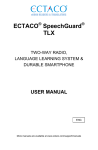
(3) SR84
OUT1 OUT2 EV1 EV2
SV2
MAN SB
111
100
11
EV3
96
48
AT
REM STBY COM
DISP
ENT
44.6
14
5
15
6
16
7
2-2. Mounting
91.6
13
4
17
8
PPO
9
Panel cutout
18
S74C-001
+1.0
0
+0.8
12
3
+0.8
2
92 0
11
130 min.
Note: The environmental conditions belong to IEC664
installation category II and the degree of pollution is
rated as 2 under this standard.
(48 × N – 3)
+0.6
45 0
1
92 0
AT
19
MADE IN JAPAN
CAUTION
For safety’s sake and to maintain the proper functioning of the
product, you should not draw it out from its case. If it is
necessary to draw out the instrument, contact our office in your
neighborhood.
10
Unit: mm
20
21
22
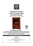
(4) Current transformer (CT) for heater break alarm
For 0-30 A (CTL-6-S)
For 0-50 A (CTL -12-S36-8)
ø 2.36
(1) Machine the mounting hole by referring to the panel
cutout drawings in Section 2-3.
(2) Applicable thickness of the mounting panel is from 1.0 to
4.0 mm
(3) This product is provided with pawls which fix it when it is
pressed straight into the front panel.
9
21
2.8
3
10.5
25
40
ø 5.8
ø 12
7.5
15
40
5
30
30
40
5
15
10
5
5
2-3. Drawings showing external dimensions and panel
cutout
Unit: mm
2- ø 3.5
2-M3
(1) SR82
72
11
111
100
2-4. Wiring
WARNING
• The product must be disconnected from its power source
during wiring operation so as to prevent electric shock.
• The protective conductor (earth) terminal
must be
grounded prior to use. Otherwise, electric shock may result.
• Do not touch the wired terminals and charged devices while
power is on.
OUT
EV1
EV2
AT
REM
STBY
72
EV3
MAN
SV2/SB COM
DISP
AT
ENT
100 min.
2
16
9
3
17
10
4
18
11
5
19
6
20
7
21
67.6
15
12
PPO
100 min.
8
1
13
S72C-001
(1) Wiring should be carried out according to the drawings in
"2-5. Terminal arrangement." Confirm that there is no
wrong connection.
(2) Use crimp terminals which meet the M3.5 screw and are
less than 7 mm in width.
(3) For thermocouple input, select a compensation wire
suitable for the particular type of thermocouple.
(4) For R.T.D. input, each lead should be less than 5Ω in
resistance and three leads should have the same resistance.
(5) The input signal line should be conducted safely apart
from high voltage power lines.
(6) Shield wiring (one-point grounding) works effectively
against static induction noise.
(7) Twisting the input signal wire at equal intervals is
effective against electromagnetic induction noise.
(8) For power lines, use wire or cable which is 1 mm2 in size
or thicker and is equivalent to or higher in grade than
600V vinyl insulated wire.
(9) Earth wiring should be carried out with less than 100 Ω
ground resistance by using wire which is 2 mm2 or thicker.
(10) Noise filter: If the instrument appears to be easily affected
by power supply noise, use a noise filter for preventing
malfunction. The noise filter should be mounted on the
grounded panel and make wiring between the controller
and the power terminal as short as possible.
68 +0.7
0
67.6
+0.7
68 0
14
MADE IN JAPAN
Panel cutout
Unit: mm
(2) SR83
96
11
111
100
96
˚C
OUT1 OUT2 EV1
EV2
EV3
AT
SV2
MAN SB
RUN
REM STBY COM
DISP
AT
ENT
91.6
2
22
32
12
3
23
33
13
4
24
34
14
5
25
35
15
6
26
36
16
7
27
37
17
8
28
9
29
10
30
38
39
92 0
11
130 min.
31
91.6
21
+0.8
130 min.
1
+0.8
92 0
18
PPO
S73C-001
40
MADE IN JAPAN
19
20
Panel cutout
Unit: mm
-3-
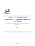
(3) SR84
Make this wiring as short as possible.
DI1
2
12
DI2
3
COM
4
+
5
- 15
-
6
16
A
7
17
8
18
-
! 11
+
1
*1
SPECIFICATION
A-output
RS-232C
RS-485
Protective Protective
wiring
wiring
1
+
RD
+
100-240 AC
50/60Hz
100240V AC
SD
OUT
TERMINAL
22
21
IN
1 Output
Controller
SG
SG
Noise filter
L
100-240VAC
50/60Hz12VA
! 11
+
12
-
N
24VDC 8W
/24VAC
50/60Hz9VA
13
14
OUTPUT
4-20mA DC
0-10V
DC
30mA12VDC
CT/REM
+ +
B
DC
-
-
B
Recommended noise filter: TDK's ZMB2203-13
COM
EV1
1A240VAC
EV2
1A240VAC
EV3
1A240VAC
19
9
10
2.5A240VAC
21
22
20
*1
(11) Connection of current transformer (CT):
Pass one load wire through the hole specifically provided
for CT. CT terminals on the secondary side are wired to
the CT input terminal of the SR80 controller.
1
! 11
DI1
2
12
DI2
3
COM
4
+
-
RD
+
SD
+
DC
-
-
5
6
+
A
7
- 17
B
8
18
B
9
19
10
! 11
+
12
-
N
24VDC 8W
/24VAC
50/60Hz9VA
21
OUTPUT1
14
-
CT/REM
+ +
L
100-240VAC
50/60Hz12VA
13
- 15
+
*1
SPECIFICATION
A-output
RS-232C
RS-485
1
To CT input terminal of the controller
(No polarity)
SG
SG
TERMINAL
21
22
2 Output
4-20mA DC
0-10V
DC
30mA12V DC
2.5A240V AC
OUTPUT2
16
22
4-20mA DC
0-10V
DC
30mA12VDC
2.5A240V AC
COM
EV1
1A240VAC
EV2/EV3
1A240VAC
20
*1
Wiring for heater (load)
2-6. Terminal arrangement table
2-5. Terminal arrangement
Power terminal
(1) SR82
1
DI2
15
2
+
3
*1
8
!
16
9
17
10
18
11
! 8
L
100-240VAC
50/60Hz12VA
9
N
CT/REM
+ +
DC
-
-
-
4
A
5
B
6
B
7
COM
EV1
1A240VAC
EV2/EV3
1A240VAC
19
+
20
-
21
12
13
14
+
24VDC 8W
/24VAC
50/60Hz9VA
-
*1
SPECIFICATION
A-output
RS-232C
RS-485
OUTPUT
4-20mA DC
0-10V
DC
30mA12VDC
16
+
-
SG
SG
SD
RD
+
-
FG
+
SLD
25
RD
SD
SG
SG
DG
TERMINAL
22
24
23
1
21
DI1
2
22
DI2
3
COM
4
-
DB
+
DA
+
21
*1
SPECIFICATION
A-output
RS-232C
RS-485
CC-Link
+ +
A
DC
-
-
N
! 11
+
12
-
24VDC 8W
/24VAC
50/60Hz9VA
-
15
OUTPUT
4-20mA DC
DC
0-10V
30mA12V DC
5
25
6
26
16
2.5A240VAC
7
27
17
COM
EV1
1A240VAC
EV2
1A240VAC
EV3
1A240VAC
28
18
9
29
19
10
30
20
21
-
FG
DI1
2
22
12
+
!
1
DI2
3
23
13
COM
4
24
5
25
DB
CT/REM
DA
+ +
*1
SPECIFICATION
A-output
RS-232C
RS-485
CC-Link
100-240VAC
50/60Hz12VA
14
8
SG
SG
DG
-
12
B
+
+
L
SLD
RD
SD
25
TERMINAL
23
24
11
B
2 Output
22
+
24
13
13
R.T.D.: A, Thermocouple/voltage/current: +
R.T.D.: B
R.T.D.: B, Thermocouple/voltage/current: –
Contact: COM, SSR drive voltage/voltage/current: +
Contact: NO, SSR drive voltage/voltage/current: –
Contact: NC
Contact: COM, SSR drive voltage/voltage/current: +
Contact: NO, SSR drive voltage/voltage/current: –
Contact: NC
Contact: COM
Contact: NO (EV1)
Contact: NO (EV2)
Contact: NO (EV3)
5
6
7
12
13
14
–
–
–
19
20
21
–
7
8
9
7
8
9
Remote input
(option)
Heater break alarm
(option)
Analog output
(option)
Communication
(option)
+
–
+
–
+
–
RS-232C: SG RS-485: SG
SD
+
RD
–
3
4
3
4
16
17
16
17
18
5
6
5
6
21
22
23
24
25
5
6
5
6
21
22
1
21
22
External input (DI)
(option)
Contact: COM
Contact: NO (DI1)
Contact: NO (DI2)
15
1
2
4
2
3
4
2
3
Event output
(option)
13
23
10
14
15
16
–
–
–
17
18
19
20
14
15
–
16
17
–
18
19
20
–
14
15
16
–
–
–
17
18
19
20
CT/REM
-
21
*1
!
11-12
Control output 2
2.5A240VAC
SR84
11-12
Control output 1
TERMINAL
18
17
SR83
1
2
1
2
output output output output
8-9
Input
(2) SR83
1 Output
100-200V AC
24V AC
24V DC
Protective conductor
terminal
COM
DI1
SR82
Name of terminal and description
-
-
+
+
14
15
6
26
7
27
B
8
28
18
B
9
29
19
10
30
20
-
DC
*1
11
A
-
L
100-240VAC
50/60Hz12VA
3. Front panel
3-1. Drawing and names of parts
As an example, the front panel of SR83 is shown below.
! 11
+
12
-
N
PV
24VDC 8W
/24VAC
50/60Hz9VA
1
PV display
°C
OUTPUT1
4-20mA DC
0-10V
DC
30mA12V DC
2.5A240VAC
SV
2
SV display
OUTPUT2
16
4-20mA DC
0-10V
DC
30mA12V DC
17
2.5A240VAC
3
OUT1 OUT2 EV1
Action display LED
EV2
EV3
AT
SV2
MAN SB
RUN
REM STBY COM
DISP
COM
EV1
1A240VAC
EV2/EV3
1A240VAC
4
Key switches
AT
SR83
-4-
ENT
14
15
–
16
17
–
18
19
20
–
(5) AT (auto tuning) key
• Used to prepare for execution/stop of auto tuning action
(in mode 0 screen group).
• Moves screens backward, i.e., in the direction opposite to
moves by the
key (in mode 1 screen group).
(6) ENT (entry/registration) key
• Registers data changed by means of
or
key on
any of the mode 0, 1 and 2 screen groups. (The decimal
point of the least digit goes out.)
• When pressed continuously for 3 seconds on the 0-1 and 02 control output screens, switching between manual and
auto of control output is accomplished.
3-2. Description of front panel parts
1
PV display (red)
(1) Displays current measured value (PV) on the mode 0 basic
screen.
(2) Displays parameter type on each parameter screen.
(3) Displays error message when trouble arises in the system.
2
SV display (green)
(1) Displays target set value on the mode 0 basic screen.
(2) Displays selected item or set value on each parameter
screen.
3
Action display LED
(1) OUT1 monitor LED (green)
• For contact or SSR drive voltage output, the LED lights
when output turns ON and goes out when output turns
OFF.
• For current or voltage output, the light intensity changes
in proportion to the rise and fall of output level.
(2) OUT2 monitor LED (green)
• For contact or SSR drive voltage output, the LED lights
when output turns ON and goes out when output turns
OFF.
• For current or voltage output, the light intensity changes
in proportion to the rise and fall of output level.
(3) EV1 (Event 1) monitor LED (orange)
• Lights when event 1 is in action.
(4) EV2 (Event 2) monitor LED (orange)
• Lights when event 2 is in action.
(5) EV3 (Event 3) monitor LED (orange)
• Lights when event 3 is in action.
(6) AT (Auto Tuning) monitor LED (green)
• Lights during AT standby and flashes during execution
of AT.
(7) MAN (Manual) monitor LED (green)
• Flashes during MAN execution (control output is in
manual operation).
(8) SV2/SB monitor LED (green)
• Lights while SV2 is in use.
• Lights while set value bias is in use.
• Flashes during ramping execution, goes out when
ramping stops if it is for SV1 but lights if it is for SV2.
(9) REM (Remote) monitor LED (green)
• Lights when rEM is selected for remote setting.
• Flashes in case remote input is below the remote
switching set value and local SV is being used.
• Goes out when Loc is selected for remote setting.
(10) STBY (Standby) monitor LED (green)
• Lights when Stb is selected for STBY setting and goes
out when EXE is selected.
(11) COM (Communication)/RUN monitor LED (green)
• Lights when COM is set for communication mode and
goes out when LOC is set.
4
4. Screens
4-1. Power application and initial screen display
Upon applying power, the power-on initial screens shown below
come onto display, each for about 1.5 sec. Then the basic screen
of the mode 0 screen group is displayed.
Power
turned on
Series code
Input type (
Power-on
initial
screens
: Thermocouple,
: R.T.D.,
: voltage (mV),
: voltage (V),
: current (mA). )
OUT1 output type (
OUT2 output type (
Contact,
current,
Contact,
current,
SSR drive voltage,
voltage)
SSR drive voltage,
voltage)
Basic screen of mode 0 screen group
4-2. Screen configuration
In the SR80 series, screens are divided by the frequency of use for
the operation of the controller into the following screen groups.
(1) Mode 0 screen group
The group includes the basic screen (for setting target
value and checking current measured value) which is used
in relatively high frequency in the operation, PID
parameters and the screen for event setting, etc.
(2) Mode 1 screen group
This group includes setting screens for changing input
status and controllability as the occasion demands and
screens for locking items intended not to be changed, these
screen being less high in frequency of use.
Key switches
(1) DISP (Disp) key
• When this key is pressed on any parameter screen, the
mode 0 basic screen returns onto the display.
(2)
(parameter) key
• When pressed on any of the mode 0 and 1 screen groups,
the next screen appears.
• When this key is pressed continuously for 3 seconds on the
mode 0 basic screen, the direct call screen of the mode 1
screen group appears.
(3)
(down) key
• When pressed on any screen, the decimal point of the least
digit flashes and data decreases or the decimal point moves
backward.
(4)
(up) key
• When pressed on any screen, the decimal point of the least
digit blinks and data increases or the decimal point moves
forward.
-5-
4-3. Key sequence
Note 1: Screen frames in 4-2 are as follows.
Mode 1
To 1-0
Screens always shown by key operation or some other means.
Screen displayed or skipped depending on input/output types
and control action settings.
To 0-18
Screens displayed only when appropriate options are added
or selected.
key
When
or
has been set in event alarm mode setting
screens, the set value setting screen for the relevant event
shall not be displayed.
3 seconds
Mode 0
0-0
0-10
Basic screen Initial value: Lower limit value of measuring range
EV1 set value setting screen Initial value: Higher limit value of
setting range
Setting range: Within measuring range
Setting range: Within measuring range
PV is displayed, and SV is displayed and set.
EV1 set value is set.
0-1
0-11
OUT1 Control output value display screen
(Setting OUT1 manual operation)
EV2 set value setting screen Initial value: Lower limit value of
setting range
Setting range: Within measuring range
OUT1 control output value is displayed in SV display. When ENT key is
pressed for 3 seconds on this screen, MAN lamp flashes and OUT1 is
changed to manual operation. For details, see Section 5-2.
0-2
EV2 set value is set.
0-12
OUT2 Control output value display screen
(Setting OUT2 manual operation)
EV3 set value setting screen Initial value:
This screen is not displayed when
scaleover has been selected.
OUT2 control output value is displayed. When ENT key is pressed for 3
seconds on this screen, MAN lamp flashes and OUT2 is changed to
manual operation. For details, see Section 5-2.
EV3 set value is set.
0-3
SV1 setting screen
PID parameters for control output 1 (OUT1) of SV1
Initial value: 0 Unit
Setting range: Within set limiter range
SV1 is set.
0-13
Proportional band setting screen Initial value: 3.0%
0-4
SV2 setting screen
Setting range: oFF, 0.1 - 999.9%
Initial value: 0 Unit
Setting range: Within set limiter range
When
P≠OFF
SV2 is set.
A ratio (%) to measuring range at which control output changes are set.
The level of control output changes in proportion to the difference
between PV value and SV value.
When oFF is set, control output is put in ON-OFF action.
When P=OFF
0-5
Set value bias setting screen Initial value: 0 Unit
Setting range: -1999
0-14
9999 Unit
Hysteresis setting screen
Set value bias is set. The set value is valid while DI to which SB is
assigned is shorted, and is added to target value (SV).
For details, see Section 4-6 (1).
Initial value: 20 Unit
Setting range: 1 1000 Unit
Hysteresis in ON-OFF action is set.
0-6
0-15
SV1/SV2 switching screen Initial value: SV1
Integral time setting screen Initial value: 120 seconds
Setting range: SV1, SV2
Setting range: oFF, 1
SV1: Control is carried out according to the setting of SV1.
SV2: Control is carried out according to the setting of SV2.
This screen is not displayed when non or sb has been set for SV_m.
6000 seconds
This is the function to correct any offset caused by proportional action.
0-7
Remote switch screen
Initial value: Loc
Setting range: Loc, rEm
0-16
Derivative time setting screen Initial value: 30 seconds
Setting method of SV value is selected.
Loc: Local SV (SV to be set by key operation)
rEm: Remote SV (SV to be set by remote input)
Setting range: oFF, 1
3600 seconds
A change in control output is estimated, overshoot due to integration is
suppressed, and control stability is increased.
0-8
Remote monitor screen
0-17
Remote input value is displayed.
Manual reset value setting screen Initial value: Output 1: -50.0%
Output 2: 0.0%
Setting range: -50.0 50.0%
Manual reset value is used to increase or decrease output to correct an
offset.
0-9
Standby switching screen
Initial value: EXE
Setting range: EXE, Stb
Control output can be put in the state of standby.
EXE: Ordinary control is carried out.
Stb: Control is stopped and control output is turned to 0%.
-6-
To 1-12
PID parameters for control output 2 (OUT2) of SV1
Mode 1
When the DISP key is pressed on the 1-0 direct call screen,
the 0-0 basic screen returns onto the display.
1-0
0-18
Direct call screen
Initial value: 1
Setting range: 1 69
When the screen No. you want to call in the mode 1 screen group is
set, that screen is displayed.
Proportional band setting screen Initial value: 3.0%
Setting range: oFF, 0.1
999.9%
When
P≠OFF
1-1
When P=OFF
EV1 alarm mode setting screen Initial value: Higher limit absolute
0-19
Hysteresis setting screen
Initial value: 20 Unit
Setting range: 1 1000 Unit
value alarm
Setting range: 8 types
Sco or Hb
Please refer to “6-2 Event type list.”
1-2
EV1 hysteresis setting screen
Initial value: 20 Unit
Setting range: 1 1000 Unit
0-20
Integral time setting screen Initial value: 120 seconds
Setting range: oFF, 1
Hysteresis during the event action is set.
6000 seconds
1-3
EV1 standby setting screen
0-21
Derivative time setting screen Initial value: 30 seconds
Setting range: oFF, 1 - 3600 seconds
0-22
Dead band setting screen
Initial value: 0.0
Setting range: -1999
1-4
Initial value: oFF
Setting range: oFF, 1 - 4
Event output action to be used, with or without standby action, is set.
For details, see Section 6-3.
oFF: Alarm action without standby
1: Alarm action with standby (when power is ON)
2: Alarm action with standby (When power is On and STBY is
in execution)
3: Alarm action with standby (When power is ON, STBY is in
execution, and SV is changed)
4: Control action without standby
EV1 delay time setting screen
5000 Unit
In case 2-output control is carried out, the action range of control
output 2 has to be set by taking characteristics of the object to be
controlled and any energy-saving effect into account.
Initial value: oFF
Setting range: oFF, 1
9999 Sec.
Delay time during event action is set.
For details, see Section 6-4.
1-5
EV2 alarm mode setting screen Initial value: Lower limit
PID parameters for control output 1 (OUT1)
of SV2/SB and Remote
absolute value alarm
Setting range: 8 types
PID parameters for control output 2 (OUT2)
of SV2/SB and Remote
0-23
Sco or Hb
1-6
EV2 Hysteresis setting screen
0-28
When
P≠OFF
Initial value: 20 Unit
Setting range: 1 1000 Unit
Hysteresis during event action is set.
When P=OFF
0-24
Please refer to “6-2 Event type list.”
When
P≠OFF
1-7
EV2 standby setting screen
When P=OFF
0-29
Initial value: oFF
Setting range: oFF, 1 - 4
Event output action to be used and standby action are set.
For details, see Section 6-3.
1-8
EV2 delay time setting screen Initial value: oFF
0-25
Setting range: oFF, 1
9999 Sec.
Delay time during event action is set.
For details, see Section 6-4.
0-30
1-9
EV3 alarm mode setting screen Initial value: Scaleover
0-26
Setting range: 8 types
0-31
Sco or Hb
Please refer to “6-2 Event type list.”
1-10
EV3 Hysteresis setting screen
0-27
Initial value: 20 Unit
Setting range: 1 1000 Unit
Hysteresis during event action is set.
1-11
EV3 standby setting screen
0-32
Initial value: oFF
Setting range: oFF, 1
4
Event output action to be used and standby action are set.
For details, see Section 6-3.
When the DISP key is pressed in the mode 1 screen group,
the 1-0 direct call screen returns onto display.
To return to 0-0.
NOTE: Functions, initial values and setting ranges of the 0-25 to 0-32
screens are the same as the other PID parameters.
-7-
To 1-36
1-12
1-22
EV3 delay time setting screen
Initial value: oFF
Setting range: oFF, 1
Remote bias value setting screen Initial value: 0 Unit
Setting range: -1999
9999 Sec.
1-13
1-23
Analog output mode setting screen
Initial value: PV
Setting range: 5 types
Remote filter setting screen
One of the five types shown in the table below is assigned to analog
output.
PV [
]
OUT1 [
]
SV [
]
OUT2 [
]
DEV [
]
Remote switching point setting screen
Initial value: oFF
Setting range: oFF, 0.1 50.0%.
Remote switching point is set. For details, see Section 4-6(3).
Initial value: As per table below
Setting range: As per table below
1-25
Lower limit scale of analog output is set.
It is conditional that Ao_L≠Ao_H.
Remote switching point Hysteresis setting screen
MODE
Setting range
PV, SV
Within measuring
range
Initial value: 2.0%
Setting range: 0.1 10.0%
Initial value
Lower limit value of
measuring range
-100.0
100.0%
-100.0%
0.0
100.0%
0.0%
Hysteresis at the remote switching point is set.
1-26
Remote lower limit scale setting screen
Initial value: Lower limit value of measuring range
Setting range: Within measuring range.
1-15
Analog output higher limit scale setting screen
Remote lower limit scale value is set.
It is conditional that rE_L≠rE_H.
Initial value: As per table below
Setting range: As per table below
1-27
Higher limit scale of analog output is set.
It is conditional that Ao_L≠Ao_H.
Remote higher limit scale setting screen
MODE
Setting range
PV, SV
Within measuring
range
DEV
OUT1, OUT2
Initial value: Higher limit value of measuring range
Setting range: Within measuring range.
Initial value
Remote higher limit scale value is set.
It is conditional that rE_L≠rE_H.
Higher limit value of
measuring range
-100.0
100.0%
100.0%
0.0
100.0%
100.0%
1-28
Remote tracking setting screen
Initial value: no
Setting range: no, yES
Remote SV value can be transferred to local SV value.
yES: Upon switching from remote SV to local SV, remote SV is
copied in local SV.
no: Remote tracking does not function.
1-16
DI1 setting screen
Initial value: noP
Setting range: 8 types
Action for DI1 input is set. For details, see Section 4-6(2).
[
[
[
1-17
[
[
[
[
[
[
[
For details, please refer to the communication interface instruction manual.
1-29
] No processing
] Standby action (level input)
] When it is not established on
Either one of them is
the 1-52 screen
] SV1/SV2 selection (level input) displayed according to
setting on the 1-52
] SB action (level input)
SB/SV2 selection
] AT action (edge input)
setting screen
] MAN action (level input)
] DA characteristics action (level input)
] Ramp temporary stop action (level input)
] REM action (level input)
DI2 setting screen
100 Sec.
1-24
Analog output lower limit scale setting screen
OUT1, OUT2
Initial value: oFF
Setting range: oFF, 1
Remote filter is set.
1-14
DEV
1999 Unit
Remote bias value is set.
Delay time during event action is set.
For details, see Section 6-4.
Communication mode selection screen
Initial value: LOC
Setting range: COM→LOC
1-30
Communication mode is selected.
LOC mode: Only read commands by communication are valid.
COM mode: Read and write commands by communication are valid.
Only changing COM to LOC is possible by front key operation.
Communication address setting screen Initial value: 1
Setting range: 1
Initial value: noP
Setting range: 8 types
99
Machine Number(s) is set when a plurality of instruments are
connected for communication.
Action for DI1 input is set. For details, see Section 4-6(2).
For action types to be assigned, refer to those listed above.
1-31
Communication speed setting screen
1-18
Initial value: 1200 bps
Setting range: 1200, 2400, 4800,
9600, 19200 bps
A speed at which data is transmitted to host computer is set.
Heater current monitor screen
Load current detected by CT is displayed for monitoring.
In case control output is in ON-OFF action, however,
displayed when effective current is not detected.
is
1-32
Communication data format setting screen
Initial value: 7E1
Setting range: 7E1, 7E2, 7N1, 7N2
8E1, 8E2, 8N1, 8N2
1-19
Heater break action mode setting screen
1-20
Initial value: Lock
Setting range: Lock, rEAL
Heater break action mode is set.
Lock: When an alarm is output, the alarm output is locked,
that is, alarm output will continue even when CT current returns
to its normal value. Alarm output does not stop unless OFF is
set for alarm current value or power is turned OFF.
rEAL: When an alarm is output, it is released automatically
if CT current returns to its normal value.
Communication data format is set.
1-33
Communication control code setting screen Initial value: 1
Setting range: 1
Communication control code is set.
1:STX_ETX_CR 2:STX_ETX_CRLF
1-21
Communication BCC check setting screen Initial value: 1
Setting range: 1
50.0A
While control output is ON, load line current is detected by CT and
if it is smaller than the set current value, it is taken as abnormal and
an alarm is output. (Heater break must be assigned to an event.)
Operating method to be used in BCC check is set.
1: ADD 2: ADD_two’s cmp 3: XOR 4: None
1-35
Communication memory mode setting screen
Heater break loop value setting screen
Initial value: oFF
Setting range: oFF, 0.1
3:@_:_CR
1-34
Heater break alarm value setting screen
Initial value: oFF
Setting range: oFF, 0.1
3
50.0A
Initial value: EEP
Setting range: EEP, Ram, r_E
EEP: Data is written into EEPROM.
Ram: Data is written into RAM.
r_E: Data is written in EEPROM. (SV and OUT are written into RAM.)
While control output is ON, load line current is detected by CT and
if it is larger than the set current value, it is taken as abnormal and
an alarm is output. (Heater break must be assigned to an event.)
-8-
4
To 1-64
1-36
1-50
PV bias setting screen
Communication delay time setting screen
Initial value: 20
Setting range: oFF, 1
100
Initial value: 0 Unit
Setting range: -1999
1999 Unit
This is used to correct an error of input from sensor, etc.
When bias is applied, control, too, is carried out with the corrected value.
Delay time from receipt of communication command to transmission
is set.
1-51
PV filter setting screen
1-37
Initial value: oFF
Setting range: oFF, 1
Output characteristics setting screen Initial value: rA
Setting range: rA, dA
1-38
Control characteristics of control output is set.
For 2-output characteristics, see Section 6-5.
rA: The more PV value is in excess of SV value, the lower the output
(heating control).
dA: The more PV value is in excess of SV value, the higher the output
(cooling control).
1-52
SB/SV2 selection setting screen
Control output 1 proportional cycle setting screen
Initial value: contact output 30 sec, SSR drive voltage 3 sec.
Setting range: 1 120 Sec.
1-53
Proportional cycle time of control output 1 is set.
Which of SB and SV2 functions is to be used is selected and set.
non: Neither SV2 function nor SB function can be used.
SV: SV2 function can be used.
Sb: SB function (set value bias) can be used.
Initial value: Lower limit value of measuring range
Setting range: Within measuring range
Control output 2 proportional cycle setting screen
Initial value: contact output 30 sec, SSR drive voltage 3 sec.
Setting range: 1 120 Sec.
Lower limit limiter of SV set value is set,
but it is necessary that SV_L<SV_H.
1-54
SV set value higher limit limiter setting screen
1-40
Initial value: higher limit value of measuring range
Setting range: Within measuring range
SV1 control output 1 lower limit output limiter setting screen
Initial value: 0.0%
Setting range: 0.0 99.9% on condition that o_L<o_H.
Lower limit output limiter of SV1 control output 1 is set.
Higher limit limiter of SV set value is set,
but it is necessary that SV_L<SV_H.
1-55
Ramp ascending value setting screen
1-41
Initial value: oFF
Setting range: oFF, 1
SV1 control output 1 higher limit output limiter setting screen
Initial value: 100.0%
Setting range: 0.1 100.0% on condition that o_L<o_H.
1-56
Ramp descending value setting screen
SV1 control output 2 lower limit output limiter setting screen
Initial value: oFF
Setting range: oFF, 1
Initial value: 0.0%
Setting range: 0.0 99.9% on condition that o_2L<o_2H.
Lower limit output limiter of SV1 control output 2 is set.
1-43
SV1 control output 2 higher limit output limiter setting screen
1-57
1-58
Ramp multiplier setting screen
Initial value: 0.0%
Setting range: 0.0 99.9% on condition of o21L<o21H.
Lower limit output limiter of SV2 control output 1 is set.
SV2, SB/REM
control output 1 higher limit output limiter setting screen
SV2, SB/REM
control output 2 lower limit output limiter setting screen
1-59
AT point setting screen
SV2, SB/REM
control output 2 higher limit output limiter setting screen
1-60
SV1 control output 1 target value function setting screen
Initial value: 0.40
Setting range: 0.00
Control output 1 error output setting screen
1-61
SV1 control output 2 target value function setting screen
Initial value: 0.40
Setting range: 0.00 1.00
This is used for correction if overshoot or undershoot from set value
arises during execution of PID control.
1-62
Initial value: 0.0%
Setting range: 0.0 100.0%
SV2, SB/REM
control output 1 target value function setting screen
Initial value: 0.40
Setting range: 0.00 1.00
This is used for correction if overshoot or undershoot from set value
arises during execution of PID control.
Control output 1 in the case of scaleover of measured input value is set.
1-49
Control output 2 error output setting screen
1.00
This is used for correction if overshoot or undershoot from set value
arises during execution of PID control.
Initial value: 100.0%
Setting range: 0.1 100.0% on condition that o22L<o22H.
Higher limit output limiter of SV2 control output 2 is set.
1-48
Initial value: 0 Unit
Setting range: 0 5000 Unit
AT point is set. For details, see Section 4-6 (4).
Initial value: 0.0%
Setting range: 0.0 99.9% on condition that o22L<o22H.
Lower limit output limiter of SV2 control output 2 is set.
1-47
Initial value: × 1
Setting range: × 1, × 0.1
A multiplier for ramp is set.
:×1
: × 0.1
Initial value: 100.0%
Setting range: 0.1 100.0% on condition that o21L<o21H.
Higher limit output limiter of SV2 control output 1 is set.
1-46
Initial value: SEc
Setting range: SEc., min
The unit of ramp value is set.
Higher limit output limiter of SV1 control output 2 is set.
SV2, SB/REM
control output 1 lower limit output limiter setting screen
9999 Unit
Upon switching between SV and SV2 or SB switching, it is feared to
cause an abrupt change in load. By setting an amount of change
(value of descent), target value changes gradually.
Ramp unit setting screen
Initial value: 100.0%
Setting range: 0.1 100.0% on condition that o_2L<o_2H.
1-45
9999 Unit
Upon switching between SV and SV2 or SB switching, it is feared
to cause an abrupt change in load. By setting an amount of change
(value of ascent), target value changes gradually.
Higher limit output limiter of SV1 control output 1 is set.
1-42
1-44
Initial value: non
Setting range: non, SV, Sb
SV set value lower limit limiter setting screen
1-39
Proportional cycle time of control output 2 is set.
100 Sec.
PV filter is set.
1-63
Initial value: 0.0%
Setting range: 0.0 100.0%
SV2, SB/REM
control output 2 target value function setting screen
Initial value: 0.40
Setting range: 0.00 1.00
This is used for correction if overshoot or undershoot from set value
arises during execution of PID control.
Control output 2 in the case of scaleover of measured input value is set.
-9-
1-0 direct call screen
1-0 direct call screen
ENT
1-64
1-59
AT point
setting screen
key
Measuring range setting screen
↑
Several times
Decimal point flashes.
Measuring range is set. For details, see Section 6-1.
iii) The preceding screen appears every time the AT key
is pressed. (This function of AT key works only in
the mode 1 screen group.)
1-65
Decimal point position setting screen
Initial value: .
Setting range: non,
.
,
.
,
.
limiter lower limit
1-53 SV
value setting screen
The position of decimal point for linear input is set.
limiter higher limit
1-54 SV
value setting screen
AT
key
1-66
Measuring range lower limit value setting screen
Initial value: 0.0
Setting range: Minimum span 10 Unit, Maximum span 5000 Unit
Possible setting range: -1999 5000 Unit
4-5. Data change on each screen
Lower limit value of PV input for linear input is set.
1-67
To change data on each screen, press the
or
key.
Changed data should be registered by pressing the ENT key. Once
the data is registered, the decimal point on the bottom right stops
flashing and goes out.
Measuring range higher limit value setting screen
Initial value: 100.0
Setting range: Minimum span 10 Unit, Maximum span 5000 Unit
Possible setting range: -1999 5000 Unit
Higher limit value of PV input for linear input is set.
1-68
4-6. Supplementary explanation about screens
Cold contact compensation switching screen
Initial value: Int
Setting range: Int, EXt
(1) 0-5 set value bias setting screen
By setting a bias value for a target set value beforehand,
the original target set value added with the bias value
becomes the new target value when the DI assigned for SB
turns ON (shorted).
DI ON = Target set value (SV) + bias value (SB)
DI OFF = Target set value (SV)
NOTE:To use the set value bias function, you have to
assign SB to a DI and set SB for SV mode.
Switching of cold contact compensation is possible.
Int: Inside the controller
Ext: Outside the controller
1-69
Keylock setting screen
To return to 1-0
Initial value: oFF
Setting range: oFF, 1, 2, 3
On a locked screen, no data change is possible. Nonetheless, the 1-0
direct call screen and the 1-69 keylock setting screen are not locked by
setting any keylock No.
oFF: Releasing keylock (All data can be changed.)
1:
Keylock except SV, AT and MAN
2:
Keylock except SV
3:
All keylock
(2) 1-16 DI1 setting screen and 1-17 DI2 setting screen
• If you select [
], SV2 takes effect when DI input
turns ON.
• When to detect external control input signal:
Level input: The action is maintained as long as the
contact remains ON.
Edge input: The action is maintained even when the
contact is turned OFF after it has been in
action for 0.3 seconds or longer. If the
contact remains ON for 0.3 seconds
subsequently, the action is released.
• If an action of the same type is assigned to DI1 and
DI2, the assignment to DI2 becomes void.
• An action assigned to a DI cannot be controlled by key
operation. (priority is given to DI input.)
• An action through DI input is held even after release of
the DI assignment.
(3) 1-24 remote switching point setting screen
Setting a remote switching point on this screen allows
local SV to be switched to remote SV at the time when
remote input reaches the desired value (%).
• When oFF is set for remote switching point →
Conventional remote switching action
By switching to remote on the remote switching setting
screen (rEm) of the user setting screen group, local is
immediately switched to remote and the remote lamp
lights.
• When a value, i.e., not “oFF”, is set for remote
switching point → remote switching action according to
applied voltage or current.
In case the value of voltage or current input remotely
upon switching to remote on the remote switching
setting screen (rEm) exceeds the set value (%) of remote
switching point, SV is switched to remote and remote
lamp lights. If remote input falls below the set value
(%) of remote switching point, it switches to local SV
and the remote lamp flashes.
Note: There is no remote switching while AT is in
execution.
Note: If the remote input at the time when remote
switching is set on the remote switching setting
screen (rEm) is below the set value (%) of remote
switching point, the remote lamp flashes and it is
switched to local SV.
4-4. How to move from screen to screen
(1) Moving between mode 0 screen group and mode 1 screen
group
• Pressing the key continuously for 3 seconds on the
basic screen of the mode 0 screen group brings the
direct call screen of the mode 1 screen group onto
display. Pressing the DISP key on any screen of the
mode 1 screen group, the display returns to the basic
screen of the mode 0 screen group.
1-0 direct call
setting screen
0-0 Basic screen
key
3 seconds
1-69 keylock mode
setting screen
0-0 Basic screen
DISP
key
NOTE: The mark shown above means pressing the key above
the mark. This applies to all the subsequent drawings.
(2) Moving from screen to screen in the mode 0 screen group
• The next screen appears every time the
key is
pressed.
0-1 OUT1 control output
0-0 Basic screen
value display screen
key
(3) Moving from screen to screen in the mode 1 screen group
• There are three methods of moving from screen to
screen in the mode 1 screen group as shown below:
i) To press the
key in the same way as in the mode 0
screen group. (See (2) above.)
ii)To enter the number of a screen you want to call on the
1-0 direct call screen.
- 10 -
(4) 1-59 AT execution point setting screen
For the purpose of avoiding hunting due to a limit cycle
with a set SV AT execution, a virtual SV value (AT
execution point) is set for AT to run at a point away from
the actual SV value.
PV
to the control output manual mode and to set a manual control
output value.
0-1
0-2
Control output 1 →
is shown.
Control output 2 →
is shown.
In case AT is executed with SV<PV
Change to manual control mode
On a display screen of control output intended to be changed (0-1
or 0-2), press the ENT key for 3 seconds continuously. The MAN
lamp flashes and it is changed to the manual mode to allow you
to set a control output value by means of the
or
key.
Likewise, the manual control output mode is switched to the
ordinary automatic mode by continuously switching the ENT key
for 3 seconds. Then the MAN lamp goes out.
AT execution point
SV value
AT execution point
In case AT is executed with SV>PV
PV
• Rules applied to manual control
1. Manual control action and output value are kept in memory
even when power is turned OFF and is reapplied.
2. When the measuring range is changed, the manual control
mode is cancelled and replaced by automatic control mode.
3. Upon switching auto to manual, balanceless and bumpless
control is carried out. If the measured value is out of the
proportional band at the time of mode switching, however,
balanceless and bumpless control is not performed.
4. The control output range in the manual control mode is
within a range defined by output limiter. (When P=OFF or
during ON/OFF action, control is carried out with lower
limit
: 0.0% and higher limit
: 100.0%.
Nevertheless, 100% output is displayed as follows on
account of limited display space.
Note 1: For AT execution point, an absolute value of
difference between SV value and virtual SV
value is to be input.
Note 2: When 0 is set for AT execution point, SV
value serves as the AT point.
Note 3: When PV value is in the AT execution point
area, SV value serves as the AT point.
5. Supplementary notes on key operation
5-1. AT
When AT is executed, PID constants are calculated and defined
from repeated ON/OFF action (100%/0%) output for the
measuring value increase and decrease around the set value and
are stored in the internal memory to complete operation. Upon
completion, control using stored PID constants begins.
0-1
0-2
↑
Flashing
How to execute AT
1. Press the AT key in the mode 0 screen group. Auto tuning is
brought to the state of standby. (AT lamp lights.)
2. Press the ENT key to register. Auto tuning is executed. (AT
lamp flashes.)
Note: AT can be executed even with remote SV. (The
remote SV at the time when AT execution point is set
is used in the execution.)
Note: AT cannot be executed in the mode 1 screen group.
• AT is not executed in the following conditions (When the
ENT key is pressed, the AT lamp goes out.)
1. During ramp control
2. During manual operation
3. In the state of STANBY
4. “oFF” setting for proportional band (ON/OFF action)
5. Selection of 2 or 3 on the keylock mode setting screen
6. Scaleover of PV value (measured value)
Cancellation of AT
AT can be cancelled in mid-operation by pressing the AT key
again. Press the ENT key for confirmation. The AT lamp goes
out.
Note: When AT is cancelled in the mid-operation, PID
values remain unchanged.
• AT is automatically cancelled under the following
conditions:
1. Output value remains at 0% or 100% for two or more hours.
2. Power supply is interrupted due to power failure or for other
reason.
3. Scaleover of PV (measured value) during AT execution.
4. STNDBY is executed.
5-2. Manual adjustment
On the 0-1 OUT1 control output value display screen and 0-2
OUT2 control output value display screen, it is possible to change
- 11 -
↑
Flashing
6-2. Event type list
6. Supplement
Thermocouple
6-1. Measuring range list
Input type
*1 B
R
S
K1
K2
K3
E
J
T
N
PLII
WRe5-26
U
L
K
AuFe-Cr
K
AuFe-Cr
R.T.D.
Pt100
(New)
JIS/IEC
JPt100
(Old)
JIS
mV -10
0
0
0
10
0
V
-1
0
0
0
1
0
0
mA
4
10
10
20
50
50
100
1
1
2
5
5
10
20
20
Code
01
02
03
04
05
06
07
08
09
10
11
12
13
14
01
02
03
04
05
06
07
08
09
10
11
12
13
14
15
16
01
02
03
04
05
06
01
02
03
04
05
06
01
02
Event type
code
Measuring range
1800 °C
0
1700 °C
0
1700 °C
0
-100.0
400.0 °C
0.0
800.0 °C
-200
1200 °C
0
700 °C
0
600 °C
-199.9
200.0 °C
0
1300 °C
0
1300 °C
0
2300 °C
200.0 °C
-199.9
0
600 °C
-200
-100.0
-100.0
-50.0
0.00
0.0
0.0
0.0
-200
-100.0
-100.0
-50.0
0.00
0.0
0.0
0.0
Code
600 °C
100.0 °C
300.0 °C
50.0 °C
50.00 °C
100.0 °C
200.0 °C
500.0 °C
500 °C
100.0 °C
300.0 °C
50.0 °C
50.00 °C
100.0 °C
200.0 °C
500.0 °C
15
16
17
18
19
20
21
22
23
24
25
26
27
28
29
30
31
32
17
18
19
20
21
22
23
24
25
26
27
28
29
30
31
32
Measuring range
3300 °F
0
3100 °F
0
3100 °F
0
-150
750 °F
0
1500 °F
-300
2200 °F
0
1300 °F
0
1100 °F
-300
400 °F
0
2300 °F
0
2300 °F
0
4200 °F
400 °F
-300
0
1100 °F
10.0
350.0 K
0.0
350.0 K
10
350 K
0
350 K
-300
1100 °F
-150.0
200.0 °F
-150
600 °F
-50.0
120.0 °F
0.0
120.0 °F
0.0
200.0 °F
0.0
400.0 °F
1000 °F
0
-300
1000 °F
-150.0
200.0 °F
-150
600 °F
-50.0
120.0 °F
0.0
120.0 °F
0.0
200.0 °F
0.0
400.0 °F
0
1000 °F
1
measuring
Higher limit absolute value Within
range
Higher limit value of
measuring range
2
Lower limit absolute value
Within measuring
range
Lower limit value of
measuring range
3
Higher limit deviation value -1999
9999 Unit
2000 Unit
4
Lower limit deviation value
-1999
9999 Unit
-1999 Unit
5
Out of higher and lower
limit ranges
0
9999 Unit
2000 Unit
6
Within higher and lower
limit ranges
0
9999 Unit
2000 Unit
7
Scaleover
EV output continues when scaleover occurs.
8
Heater break
Event output continues when heater break alarm is
output.
1
2
3
4
OFF
5
6
ON
OFF
: Set value for action
: SV value
NOTE: Code 8 in the above table can be selected and set only
when the instrument includes the heater break alarm option.
6-3. Event standby action
• In case an event output is used as an alarm, set “oFF,” “1,” “2,”
or “3.”
• In case an event output is used as control output, set “4.”
If scaleover occurs on the event set value side, however, event
output remains OFF during standby.
• When “1” has been set for event action, the standby action
functions when:
1. power is applied.
• When “2” has been set for standby action, the standby action
functions when:
1. power is applied;
2. STBY→ EXE;
• When “3” has been set for standby action, the standby action
functions when:
1. power is applied;
2. STBY→ EXE;
3. SV is changed where standby set value is a deviation value.
(Except during remote input, though.)
• When the standby action setting is changed to “oFF” or “4”
while standby is in action, the standby action is cancelled
immediately.
• If, upon applying power, PV value is out of the range in which
event action is ON, standby action becomes void even when
“1,” “2,” or “3” has been set for it.
Scaling range: -1999 9999 count
Span: 10 5000 count
but lower limit side<higher limit side
*1 Thermocouple B: 400 °C and 750 °F
or below is not covered by accuracy
guarantee.
Note: The following codes represent the respective factory-set
measuring ranges.
Code
05
07
02
05
02
Initial value of event
set value
ON
The scaling function allows you to select
any value within the following ranges:
Input
Standard/rating
JIS K
Thermocouple
JIS Pt100
R.T.D.
0 10mV DC
Voltage(mV)
1 5V DC
Voltage(V)
4 20mA DC
Current (mA)
Setting range of
event set value
Event type
Measuring range
0.0 800.0 °C
0.0 200.0 °C
0.0 100.0
0.0 100.0
0.0 100.0
6-4. Event delay time
• If a factor which has turned event action ON disappears, the
event will not be output and delay time measurement is
aborted.
• If a factor to turn event action ON arises and delay time is
changed within the setting range of delay time, the time starting
from the occurrence of the factor to activate the event (i.e., a
total time) works as the delay time.
NOTE: If you change a measuring range code, all measuring
ranges related to data such as SV value, event set values,
PID are initialized.
NOTE: When a type code of event, remote input or analog output
is changed, all data related to it are initialized.
- 12 -
6-5. 2-output characteristics
7. Specifications
RA
Control output 1
DISPLAY
• LED display:
Control output 2
100%
50%
Display accuracy:
Range in which display
accuracy is maintained: 23˚C ± 5˚C
Display resolution:
Depends on measuring range
(0.001, 0.01, 0.1, 1)
Sampling cycle:
250 msec. (0.25 sec.)
Action display/color: 11 types, LED lamp display
Control output:
(OUT1, 2)/
green
Event action
(EV1, 2, 3)/
orange
Auto tuning action (AT)/green
Manual control action (MAN)/green
Set value bias action (SV2/SB)/green
Remote action
(REM)/green
Standby action
(STBY)/green
Communication status(COM/RUN)/
green
0%
-DB
DA
DB=0
Control output 1
+DB
Control output 2
100%
50%
0%
-DB
DB=0
Set value (SV)
Measured value (PV)
Low
Measured value (PV) display/
7-segment red LED 4 digits
Set value (SV) display/
7-segment green LED 4 ditits
± (0.25% FS + 1 digit)
+DB
High
SETTING
• Setting method:
Setting range:
6-6. Error messages
If a problem arises in the controller, one of the following error
messages will be displayed on the screen.
(1) Problems with measured input (shown on PV display)
Setting limiter:
Indicates thermocouple break, R.T.D.A break, or
PV value being about 10% on the high side of
higher limit of measuring range.
Set value resolution:
Setting key type:
Indicates PV value being about 10% on the low
side of lower limit of measuring range due to
inverse polarity of input wiring.
• Ramp control upon
reaching set value:
Ramp setting range:
Ramp unit time:
Indicates that Reference contact (CJ) defects to
higher side for thermcocouple input.
Ramp rate:
Indicates that Reference contact (CJ) defects to
lower side for thermcocouple input.
INPUT
• Thermocouple:
Indicates break of B (middle) or multiple break
of A.B.B. for R.T.D. input.
Indicates break of B (bottom) for R.T.D. input.
(2) Problems with remote input (shown on SV display)
Indicates that remote input value has exceeded
higher limit of remote scale (+110%FS).
Indicates that remote input value has fallen below
lower limit of remote scale (-10%FS).
•
(3) Problems with heater break alarm (shown on SV display)
•
Indicates that CT input value has exceeded 55A.
(Indicates that CT input value has fallen below
-5A.)
•
NOTE: If a problem arises and its cause appears to
lay inside the instrument, please call our
representative or sales office.
•
•
•
•
- 13 -
By front key switch operation
Same as measuring range
(within setting limiter)
Higher and lower limits separate
setting; free within measuring range
(Lower limit < higher limit)
Depends on range and scaling
(0.001, 0.01, 0.1, 1)
6 types - PARA (parameter selection),
UP, DOWN, AT, ENT and DISP keys
Ascending/descending ramp control
OFF, 1~9999 Units
/sec, /min switching by front key
operation and communication
×1, ×0.1 switching by front key
operation and communication
B, R, S, K, E, J, T, N, PL II, WRe526, {L, U (DIN43710)}K, AuFe-Cr
Kelvin unit input
Allowable external
resistance range:
100Ω maximum
Input impedance:
500kΩ minimum
Burnout function:
Standard feature (up scale)
Cold junction
temperature compensation
accuracy:
± 2˚C (within a range from 5 to 45˚C)
R.T.D.:
Pt100/JPt100
Amperage:
About 0.25 mA
Allowable range of
lead wire resistance:
5Ω maximum/wire
Voltage
(multiple input):
-10~10, 0~10, 0~20, 0~50, 10~50,
0~100mV DC, or -1~1, 0~1, 0~2,
0~5, 1~5, 0~10V DC
Input impedance:
500kΩ minimum
Current:
0~20mA, 4~20mA DC
Receiving impedance: 250Ω
Sampling cycle:
250 msec. (0.25 sec.)
PV bias:
-1999~1999 Units
PV filter:
OFF, 1~100 sec.
Reference contact
compensation
switching:
INT (internal)/EXT (external)
switching by front key operation
Isolation:
Insulated from various outputs (not
insulated from system, DI (external
switching input) and CT input )
load current 30mA maximum
Current (I): 4~20mA DC, load
resistance 600Ω maximum.
Voltage (V): 0~10V DC, load current
2mA maximum
CONTROL (SR82: 1 output only)
• Control system:
One output operation:
Expert PID control with auto tuning
function
RA (reverse characteristics):
Heating action
DA (due characteristics):
Cooling action
Two output operation (option):
Expert PID + PID (control outputs 1
and 2 individually in action) control
with auto tuning function
RA (reverse characteristics):
Heating action (output 1 side and
cooling (output 2 side)
DA (due characteristics):
2-stage heating action (by both of
control outputs 1 and 2)
• PID
(Control outputs 1 and 2 individually)
Control output 1:
Proportional band (P);OFF,
0.1~999.9% (OFF=ON/OFF action)
Integral time (I): OFF, 1~6000 sec.
(OFF= with manual reset)
Derivative time (D):
OFF, 0~3600 sec.
Manual reset: -50.0 to +50.0% (valid
when I=OFF)
ON/OFF hysteresis: 1~1000 unit
(valid during ON/OFF action)
Control output 2 (only when two output option is added):
Proportional band (P): OFF,
0.1~999.9% (OFF=ON/OFF action)
Integral time (I): OFF, 1~6000 sec.
Derivative time (D):
OFF, 0~3600 sec.
ON/OFF hysteresis: 1~1000 Units
(valid during ON/OFF action)
Dead band: -1999~5000 Units
Separate setting for SB/SV2 is
possible. Setting range is the same as
the one listed above.
• Proportional cycle:
(for contact and SSR drive voltage
output)
Control output 1:
1~120 sec.
Control output 2:
1~120 sec.
• AT point setting:
0-5000 Units
• Control output
characteristics:
RA (reverse characteristics)/DA (due
characteristics) switchable by front
key operation or DI (external
switching input) through
communication.
• Higher and lower limit
output limiter
(individually for control
outputs 1 and 2):
Lower limit side: 0.0~99.9%,
Higher limit side: 0.1~100.0% on
condition that lower limit value <
higher limit value.
Separate setting for SB/SV2 is possible.
Setting range is the same as the one
listed above.
• Control output at time of error
(individually for control outputs 1 and 2) :
0.0~100.0%
• Control output type/rating
(common to control outputs 1 and 2):
Contact (Y): 240V AC 2.5A/resistive
load
SSR drive voltage (P): 12V±1.5V DC,
• Output resolution
Control output 1:
Control output 2:
• Sampling cycle:
• Manual control
Manual switching:
About 0.0125% (1/8000)
About 0.5% (1/200)
250 msec. (0.25 sec.)
Front key operation or DI (external
switching input) through
communication
Manual control output: 0.0-100.0% (out of output limiter
range possible)
Setting resolution:
0.1%
Manual←→automatic
control:
Balanceless bumpless (within
proportional band, though)
• Isolation:
Insulated between control output and
system and various inputs (not
insulated between control output of
current, voltage or SSR and analog
output)
EVENT OUTPUT (optional)
• Number of event
outputs:
SR82 - 2
SR83 - 3 (2 when 2 output option is
added)
SR84 - 3 (2 when communication
option, analog output option and/or 2
output option are added)
(In case of 2 event outputs, EV2 and
EV3 are common output with OR.)
• Event type:
Selectable from 8 types (7 types when
hearter break alarm option is not
added)
A_Hi: Higher limit absolute value
alarm
A_Lo: Lower limit absolute value
alarm
D_Hi: Higher limit deviation value
alarm
D_Lo: Lower limit deviation value
alarm
D_i: Higher/lower limit deviation
value alarm (within range)
D_o: Higher/lower limit deviation
value alarm (out of range)
Sco: Scaleover (input trouble alarm)
Hb: Hearter break alarm (selectable
only when heater break alarm
option is added)
• Event setting range
Deviation value alarm
Higher limit alarm:
-1999~9999 Units
Lower limit alarm:
-1999~9999 Units
Higher/lower limit alarm:
0~9999 Units
Absolute value alarm
Both higher and lower limits:
Within measuring range
Event setting system: By front key operation
• Event action:
ON/OFF action
• Event hysteresis:
1~1000 Units
• Standby/no standby
action:
Selectable from 5 types
Alarm action without standby
Alarm action with standby (When
power is ON)
Alarm action with standby (When
power is ON, when standby is
switched to execution)
- 14 -
Alarm action with standby (When
power is ON, when standby is
switched to execution, including the
time when SV is changed)
Control action
• Event action delay:
OFF, 1~9999 sec.
• Event output/rating:
Contact 240V AC 1.0A
(resistive load)
• Output updating cycle: 250 msec. (0.25 sec.)
•
•
•
•
•
•
•
•
•
•
•
•
•
•
•
•
•
•
•
•
alarm)
• Remote setting:
Switching to remote:
• Remote switching
point:
• Remote switching
hysteresis:
• Remote scaling:
ANALOG OUTPUT (optional, not selectable together with
communication type (1) and (2))
The number of analog
output:
1
Output signal:
Selectable from 5 types
(3 types for instrument with one
output)
PV:
Measured value
SV:
Set value
DEV:
Bias output
OUT 1:
Control output 1
OUT 2:
Control output 2
(selectable only when 2
output option is added)
Output type/rating
0~10 mV DC/FS Output impedance:
10Ω
0~10 V DC/FS Load current:
2mA maximum
4~20mA DC/FS Load resistance:
300Ω maximum
Output scaling
PV/SV: Within measuring range
(inverted scaling possible)
OUT1/OUT2: 0.0-100.0% (inverted
scaling possible)
DEV: -100.0~100.0% (inverted
scaling possible ) on condition that
Ao_L ≠ Ao_H
Output accuracy:
±0.25% FS (to displayed value)
Output resolution:
0.01% FS (1/10000)
Output updating cycle: 250 msec. (0.25 sec.)
Isolation:
Insulated from system and various
inputs (not insulated from control
outputs I, P and V)
Accuracy of setting:
Setting signal:
•
•
•
•
•
•
•
•
•
•
HEATER BREAK ALARM (optional, not selectable together
with REM input )
Current capacity:
30A or 50A CT to be specified when
order is placed.
Alarm action:
Heater amperage detected by external
CT (CT attached).
Alarm output ON upon detection of
heater break while control output is
ON.
Alarm output ON upon detection of
heater loop alarm while control output
is OFF.
Current setting range: 0.1~50.0A (Alarm action stops when
OFF is set.)
Setting resolution:
0.1A
Current display:
0.0~55.0A
Display accuracy:
Approx. 3% FS
(for 50Hz/60Hz sine wave)
Minimum time for
action confirmation:
ON (OFF) time 250 msec. min
Alarm output/rating:
Contact 240V AC 1.0A
(resistive load)
Alarm action display: ”Event” lamp lights during action.
Alarm holding mode: Switchable between holding and not
holding on the setting screen.
Sampling time:
500 msec. (0.5 sec.)
Isolation:
Insulated between CT input and
various outputs (not insulated from
system and other inputs)
•
•
•
•
•
•
•
•
•
•
•
•
REMOTE (optional, not selectable together with heater break
•
- 15 -
Remote bias:
Remote filter:
Sampling cycle:
Isolation:
By external analog signal
By key, communication and DI
(external switching) input (valid only
when DI option is added)
Remote/local switching function by
remote signal
OFF, 0.1~50.0%
0.1~10.0%
Within measuring range (inverted
scaling possible)
±(0.25% SF + 1 digit)
0~10V, 1~5V DC Input impedance:
500kΩ
4~20mA DC Receiving impedance:
250Ω
-1999~1999 units
OFF, 1~100 sec.
500 msec. (0.5 sec.)
Insulated between remote input and
various outputs (not insulated from
system and vaious inputs)
COMMUNICATION (optional, not selectable together with
analog output for SR82 and SR84)
Communication
type (1):
RS-232C, RS-485
Communication system:RS-232C 3-line half duplex system
RS-485 2-line half duplex multiple
drop (bus) system
Synchronization
system:
Start-stop synchronization system
Communication
distance:
RS-232C maximum 15m
RS-485 maximum 500m (depending
on conditions)
Communication speed: 1200, 2400, 4800, 9600, 19200 bps
Data bit length:
7 bits, even parity, stop bit 1
7 bits, even parity, stop bit 2
7 bits, no parity, stop bit 1
7 bits, no parity, stop bit 2
8 bits, even parity, stop bit 1
8 bits, even parity, stop bit 2
8 bits, no parity, stop bit 1
8 bits, no parity, stop bit 2
Communication
address:
1~99
Communication
memory mode:
EEP/RAM/r_E
Communication BCC: Add/Add two’s cmp/XOR/None
Communication delay
time:
OFF, 1~100
Communication code: ASCII code
Communication
protocol:
Shimaden standard protocol
The number of instruments allowed to be connected:
RS-232C 1
RS-485
32 maximum (depending
on conditions; host
included)
Isolation:
Insulated between communication
signal and various
inputs/system/various outputs
Communication
type (2):
Conforming with Mitsubishi Electric
Company’s CC-Link (only for SR83,
simultaneous selection of analog
output is not possible)
Transmission speed:
156K, 625K, 2.5M, 5M, 10Mbps
Private station:
1
Communication
method:
Polling method
Synchoronization
method:
Frame synchronous method
• Coding system:
• Transmission line:
• Transmission format:
•
•
•
•
NRZI system
Bus (RS-485)
Conforming with HDLC
• Power consumption:
• Input noise removal
ratio:
DI (EXTERNAL SWITCHING) INPUT (optional)
*DI stands for “Digital Input.”
Number of DI point:
2
DI input type:
Selectable from 8 types (7 types if the
remote option is not added.)
NOP:
No operation
STB:
Execution/standby
SB/SV2: Set value bias/set value 2
AT:
Auto tuning
MAN: Manual
STP:
Ramp temporary stop
DA:
Direct action
REM: Remote (selectable only
when remote option is
added)
DI input rating:
No-voltage contact, open collector
input (about 5V/2mA impress)
Isolation:
Insulated between DI input and
various outputs (not insulated from
system and various inputs)
• Applicable standards:
• Insulation resistance:
• Dielectric strength:
• Protective structure:
SET VALUE 2 (SV2)/Set Value Bias (SB) (optional)
(DI option is prerequisite.)
• Action input:
No-voltage contact by SB/SV2
selection through DI (external
switching) input (in action during
closed input)
• Selection of setting
Absolute value setting (SV2)
Deviation value setting (SB)
• Setting range
Absolute value setting:
Within measuring range
Deviation value setting:
-1999~5000 Units
SV2 allows PID and output limit to be
set.
•
•
•
•
•
• Material of case:
• External dimensions:
• Mounting:
• Applicable panel
thickness:
• Panel cutout size
OTHERS
Data storage:
By non-volatile memory (EEPROM)
Ambient temperate/humidity
ranges for use:
-10~+50˚C/below 90% RH (on
condition that there is no dew
condensation)
Temperature
for storage:
Between-20 and +65˚C
Temperature range for
maintaining accuracy: 23±5˚C
Power voltage:
100V-240V AC±10% (50/60 Hz),
24V AC±10% (50/ 60Hz),
24V DC±10%.
(One of the above to be specified)
• Weight
12VA maximum
Normal mode 60 dB minimum (50/60
Hz)
Common mode 140 dB minimum
(50/60 Hz)
Safety:
IEC1010-1 and EN61010-1
EMC:
EN50081-2: 1993 (EMI/Emission)
EN50082-2, 1995 (EMS/Immunity)
Between input/output terminals and
power terminal 500V DC 20MΩ
minimum
Between imput/output terminals and
protective conductor terminal 500V
DC 20MΩ minimum
1 minute at 2300V AC between
input/output terminals and power
terminal
1 minute at 1500V AC between power
terminal and protective conductor
terminal
Only front panel has simple dustproof and drip-proof structure
(equivalent to IP66)
PPO resin molding (equivalent to
UL94V-1)
SR82
H72 × W72 × D111mm
(Inside depth of panel: 100mm)
SR83
H96 × W96 × D111mm
(Inside depth of panel: 100mm)
SR84
H96 × W48 × D111mm
(Inside depth of panel: 100mm)
Push-in panel (one-touch mount)
1.0~4.0 mm
SR82: H68 × W68mm;
SR83: H92 × W92mm;
SR84: H92 × W45mm
SR82: 300g;
SR83: 420g;
SR84: 280g
Distributed in New Zealand by:
Christchurch
Ph: +6433430646
Fx: +6433430649
Auckland
098271930
098271931
www.intech.co.nz
[email protected]
The contents of this manual are subject to change without notice.
Temperature and Humidity Control Specialists
Head Office: 2-30-10 Kitamachi, Nerima-Ku, Tokyo 179-0081 Japan
Phone: +81-3-3931-7891 Fax: +81-3-3931-3089
E-MAIL: [email protected] URL: http://www.shimaden.co.jp
- 16 -
PRINTED IN JAPAN

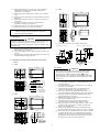

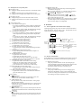
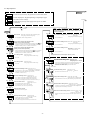
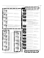

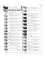

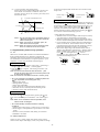
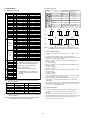
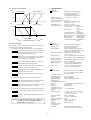

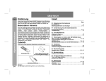


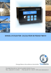
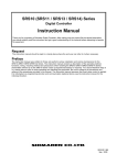

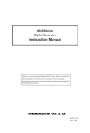
![TR4W User Manual [English Version]](http://vs1.manualzilla.com/store/data/005728234_1-e27c4fea1c6d513d6e0fdc1451ef66f1-150x150.png)