1
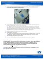
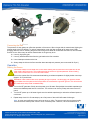
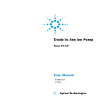
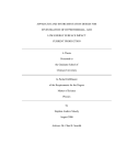
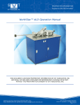
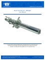
Model SVTA-RF-4.5 – Nitrogen
User Manual
THIS DOCUMENT CONTAINS PROPRIETARY INFORMATION OF SVT ASSOCIATES, INC.
AND SHALL NOT BE USED, DISCLOSED OR REPRODUCED, IN WHOLE OR IN PART,
WITHOUT THE PRIOR WRITTEN CONSENT OF SVT ASSOCIATES, INC.
7620 Executive Drive | Eden Prairie, MN 55344-3677 | USA
Phone: 952-934-2100 | Fax: 952-934-2737 | Email: [email protected] | www.svta.com
Model SVTA-RF-4.5 – Nitrogen Version 2.0 1/14
SVT Associates Proprietary Information
© 2013 SVT Associates, Inc. All Rights Reserved.
Table of Contents
Introduction .................................................................................................................................................................. 3 Precaution .................................................................................................................................................................... 3 Flow Chart .................................................................................................................................................................... 4 Unpacking and Assembly ............................................................................................................................................. 5 Assembling the Plasma Source ................................................................................................................................... 5 Removal of the RF Plasma Source Top Cover ........................................................................................................ 6 Installing the Plasma Chamber ................................................................................................................................ 8 Closed-end PBN Chamber Installation Instructions ................................................................................................. 8 PBN Chamber with Optional Aperture Installation Instructions .............................................................................. 10 Aligning the PBN Chamber .................................................................................................................................... 11 Closed-end PBN Chamber ..................................................................................................................................... 11 PBN Chamber with Optional Aperture.................................................................................................................... 11 Replacing the Shield Cover .................................................................................................................................... 12 Adjusting the PBN Cover........................................................................................................................................ 13 Adjusting the Aperture ............................................................................................................................................ 13 Installing the Shutter Paddle (Optional) ................................................................................................................. 14 Installing the Source into the Deposition Chamber .................................................................................................... 15 The Matching Network ............................................................................................................................................... 15 Electrical Connections ............................................................................................................................................ 19 Connecting the Gas................................................................................................................................................ 20 Operation ................................................................................................................................................................... 20 Starting the Source................................................................................................................................................. 20 Turning off the Source ............................................................................................................................................ 21 Maintenance ............................................................................................................................................................... 22 Changing the PBN Cover ....................................................................................................................................... 22 Appendix .................................................................................................................................................................... 23 Specifications ......................................................................................................................................................... 23 Options ................................................................................................................................................................... 24 Spare Parts List ...................................................................................................................................................... 24 Component Data Sheet .............................................................................................................................................. 25 Warranty and Limitations of Remedies ...................................................................................................................... 26 Return Policy .............................................................................................................................................................. 26 Returning Equipment for Repair or Servicing ............................................................................................................. 27 7620 Executive Drive | Eden Prairie, MN 55344-3677 | USA
Phone: 952-934-2100 | Fax: 952-934-2737 | Email: [email protected] | www.svta.com
Model SVTA-RF-4.5 – Nitrogen Version 2.0 1/14
SVT Associates Proprietary Information
© 2013 SVT Associates, Inc. All Rights Reserved
Page 2 of 27
Introduction
SVT Associates’ RF Plasma Source 4.5 has been optimized to break the N2 bond and supply sufficient nitrogen
atoms for deposition and cleaning. SVT Associates’ atom source can produce fluxes as high as 5 µm/hr under
optimal growth conditions.
The RF 4.5 is designed to mount on a standard 4.5" nipple in any orientation. This source requires water-cooling, a
gas source, a mass flow controller or leak valve, and an RF generator (if not ordered with the source). We
recommend an RF generator which is capable of supplying at least 500 watts into 50 ohms at 13.56 MHz and a gas
supply with a maximum flow rate of 10 to 20 sccm (Standard Cubic Centimeters per Minute). Although the
maximum power level and flow rate are not necessary for sustained operation, they do simplify ignition of the
plasma.
Precaution
•
Review the entire manual prior to installation and operation of the RF Plasma Source.
•
SVT Associates’ RF Plasma Source is engineered for optimum performance and reliability. Any
modification of the equipment or operation of the equipment outside the prescribed conditions in this
manual will void the warranty and may result in damage of the equipment.
•
Before installing and operating your newly delivered RF Plasma Source, inspect the shipping container
inside and out and note any visible damage. Notify SVT Associates immediately. If any damage is
noticeable, please send an email to [email protected].
•
Observe all warning and material handling instructions listed in the MSDS documentation for all materials
that are to be used in the RF Plasma Source. Keep in mind that if toxic substances are to be used they
may form on the exterior of sources or other in-vacuum equipment.
•
SVT Associates should be contacted to make arrangements to have any equipment returned for repair or
replacement. Do not discard any packing material. If it becomes necessary to ship the source back for
repair or replacement, we request the source be shipped using the original packing material.
•
All items included in this equipment package are fragile. Improper handling could damage this product.
Handle with care.
7620 Executive Drive | Eden Prairie, MN 55344-3677 | USA
Phone: 952-934-2100 | Fax: 952-934-2737 | Email: [email protected] | www.svta.com
Model SVTA-RF-4.5 – Nitrogen Version 2.0 1/14
SVT Associates Proprietary Information
© 2013 SVT Associates, Inc. All Rights Reserved
Page 3 of 27
Flow Chart
7620 Executive Drive | Eden Prairie, MN 55344-3677 | USA
Phone: 952-934-2100 | Fax: 952-934-2737 | Email: [email protected] | www.svta.com
Model SVTA-RF-4.5 – Nitrogen Version 2.0 1/14
SVT Associates Proprietary Information
© 2013 SVT Associates, Inc. All Rights Reserved
Page 4 of 27
Unpacking and Assembly
SVT Associates’ equipment is packaged with the utmost care in an effort to eliminate damage due to the shipping
process. Inspect all shipping containers and equipment for damage. Any damage noticed should be reported to
SVT Associates immediately. Also be sure to inspect all contents of the package and compare to the packing list.
Report any missing items to SVT Associates.
The RF Plasma Source 4.5 is shipped in two boxes. One box contains the plasma source head and PBN parts. The
second box contains the RF matching network. Any optional items, such as an RF generator, will be shipped in
separate boxes.
1.
Wear gloves to avoid contaminating the source. Carefully remove the plasma source from its shipping
container (Figure 1). Remove the bolts holding the stainless steel shipping tube in place. Carefully slide
the source out of the shipping tube and place it in an appropriate holder. The source is clean and has
already been outgassed and tested in a UHV system.
RF Plasma Source
Shipping
Tube
Bolts located
around flange
Figure 1
Assembling the Plasma Source
Note: Remember to handle these components in a clean room environment.
Tools Required
• Small Slotted Screwdriver
• Tweezers
• Hex Wrench Set
• Isopropyl Alcohol
Lay the tools out on the bench first. It is recommended that you use a Pana-Vise rotatable desk vise to hold the
flange and assembly.
7620 Executive Drive | Eden Prairie, MN 55344-3677 | USA
Phone: 952-934-2100 | Fax: 952-934-2737 | Email: [email protected] | www.svta.com
Model SVTA-RF-4.5 – Nitrogen Version 2.0 1/14
SVT Associates Proprietary Information
© 2013 SVT Associates, Inc. All Rights Reserved
Page 5 of 27
Assembly Hardware
Letter
Quantity
Size
A
6
0-80 X ⅛"
Stainless Steel Binding Head Screw –
Slotted (on top shield cover)
5001718
B
6
2-56 X ⅜"
Vented Stainless Steel Flat Head Screw
– Phillips (on top shield cover)
5013171
C
2
2-56 X ⅛"
Titanium, Flat Head Screw – Slotted (on
top shield cover)
5002880
D
2
2-56 X ¼"
Titanium, Vented, Binding Head Screw –
Slotted (on top shield cover)
5008113
E
1
2-56 X ⁄16"
Stainless Steel Binding Head Screw (on
top shield cover)
5001722
F
2
6-32 X ½"
Stainless Steel Socket Head Cap Screw
5002364
G
2
2-56 X ⁄16"
Tantalum Pan Head Screw – Slotted
5004104
H
2
2-56 X ⅛"
Tantalum Pan Head Screw – Slotted
5003565
I
4
2-56
Tantalum Hex Nut
5002443
J
4
2-56 X ⅜"
Tantalum Pan Head Screw – Slotted
5004103
5
3
Description
Image
Part Number
Removal of the RF Plasma Source Top Cover
4" x ¼" slit
Holding
Device
Figure 2
1.
Make sure the plasma source is securely fastened in a holding device with the 4" x ¼" slit on top.
7620 Executive Drive | Eden Prairie, MN 55344-3677 | USA
Phone: 952-934-2100 | Fax: 952-934-2737 | Email: [email protected] | www.svta.com
Model SVTA-RF-4.5 – Nitrogen Version 2.0 1/14
SVT Associates Proprietary Information
© 2013 SVT Associates, Inc. All Rights Reserved
Page 6 of 27
2.
Remove the 0-80 X ⅛" stainless steel binding head screws (A), along the seam where the top and bottom
shield covers meet (Figure 2). There are six screws, three on each side.
3.
Next remove the 2-56 X ⅜" vented stainless steel flat head screws (B) near the flange (Figure 3). There
are six screws, three on each side.
Figure 3
4.
Remove the 2-56 X ⅛" vented titanium binding head screws (C) near the tip of the source (Figure 4).
There are two screws, one on each side.
5.
Remove the 2-56 X ¼" titanium flat head screws (D) near the tip of the source (Figure 5). There are two
screws, one on each side.
Figure 5
Figure 4
6.
5
Now remove the 2-56 X ⁄16" stainless steel binding head screw (E) located on the top of the shield near
the flange. See Figure 6.
Figure 6
7620 Executive Drive | Eden Prairie, MN 55344-3677 | USA
Phone: 952-934-2100 | Fax: 952-934-2737 | Email: [email protected] | www.svta.com
Model SVTA-RF-4.5 – Nitrogen Version 2.0 1/14
SVT Associates Proprietary Information
© 2013 SVT Associates, Inc. All Rights Reserved
Page 7 of 27
7.
Carefully remove the top cover shield. Figure 7 shows what you will see after removing the shield.
Figure 7
Installing the Plasma Chamber
Locate the PBN parts and the PBN hardware package; they are packaged in the same box as the plasma source.
These parts are fragile, handle with care!
PBN Parts and Hardware
PBN Shield
PBN
Chamber
Mounting Clip
Gas Feed
Adapter Clip
Extender Tube
Figure 8
Figure 9
1.
Remove the two 6-32 X ½" stainless steel socket-head cap screws (F) and pull out the Gas Feed Adapter
Clip. See Figure 8.
2.
Carefully slide the Extender Tube out toward the tip. Remove the Extender Tube from the plasma source.
See Figure 9.
Closed-end PBN Chamber Installation Instructions
7620 Executive Drive | Eden Prairie, MN 55344-3677 | USA
Phone: 952-934-2100 | Fax: 952-934-2737 | Email: [email protected] | www.svta.com
Model SVTA-RF-4.5 – Nitrogen Version 2.0 1/14
SVT Associates Proprietary Information
© 2013 SVT Associates, Inc. All Rights Reserved
Page 8 of 27
H
Remove
PBN Cover
Nuts Remove
H
G
Loosen
G
Wire
Figure 10
Figure 11
Note: Follow steps 3-4 and omit step 5 if you have a closed-end PBN Chamber. If you need to install an
optional aperture, begin at step 5 instead to completely remove the PBN Cover.
3.
Next you must rotate the deflection plates to make room for installing the PBN Chamber. To rotate the
3
deflection plates, first remove the upper 2-56 x ⁄16" (G) and 2-56 x ⅛" (H) screws and 2-56 nuts (I)
fastening the Deflection Plates to the PBN Cover (Figures 10 and 11).
Note: Figures 10 and 11 show the PBN Chamber already installed; your PBN Chamber will not be.
4.
3
3
Loosen the bottom 2-56 x ⁄16" (G) and 2-56 x ⁄16" (H) screws and 2-56 nuts (I) fastening the Deflection
Plates to the PBN End Cover (Figures 10 and 11). Now gently rotate the Deflection Plates to clear the
center hole in the Cover. Continue with step 6.
7620 Executive Drive | Eden Prairie, MN 55344-3677 | USA
Phone: 952-934-2100 | Fax: 952-934-2737 | Email: [email protected] | www.svta.com
Model SVTA-RF-4.5 – Nitrogen Version 2.0 1/14
SVT Associates Proprietary Information
© 2013 SVT Associates, Inc. All Rights Reserved
Page 9 of 27
PBN Chamber with Optional Aperture Installation Instructions
5.
Remove the 2-56 X 1/4" titanium flat head screws (D) on the underside near the tip of the source
(Figure 21). There are two screws, one on each side. Removing these two screws will allow you to
remove the PBN Cover. (Figure 22) Be careful with the tantalum wires that attach to the Deflection
Plates, the wires have a ceramic alumina sheath; take care not to break the ceramic. (Figure 22)
Continue with step 6.
Figure 22
Figure 21
6.
You are now ready to install the PBN Chamber. Slide the Mounting Clip over the PBN Chamber, making
sure the flared side on the Mounting Clip matches the flared end on the PBN Chamber. Carefully feed the
PBN Chamber outward through the copper coil and center hole in the PBN Cover as far as it will go.
Figure 13
Figure 12
7.
Place the Extender Tube back into the plasma source. Insert the PBN Shield into the Extender Tube
(Figure 12). Place the Extender Tube back into the plasma source. Reinstall the Gas Feed Adapter Clip
(Figure 8) with its screws (F), but do not fully tighten the screws yet.
8.
Slide the PBN Chamber down toward the flange to mate with the PBN Shield and Extender Tube. Use
the four 2-56 X ⅜" tantalum pan head screws (J) to fasten the pieces together, rotating the Extender
Tube as needed (Figure 13). Do not fully tighten the screws yet. Also, be careful not to strip the screws.
Use isopropyl alcohol liberally to lubricate the threads.
7620 Executive Drive | Eden Prairie, MN 55344-3677 | USA
Phone: 952-934-2100 | Fax: 952-934-2737 | Email: [email protected] | www.svta.com
Model SVTA-RF-4.5 – Nitrogen Version 2.0 1/14
SVT Associates Proprietary Information
© 2013 SVT Associates, Inc. All Rights Reserved
Page 10 of 27
Aligning the PBN Chamber
1.
Center the PBN Chamber in the coil. When tightening the four screws that secure the PBN Chamber,
give each screw about a ¼ turn. Make sure the PBN Chamber is centered, and give each screw another
¼ turn. Continue in this fashion until all the screws are snug, but not tight.
2.
To finally secure the PBN Chamber, look to see which direction the PBN Chamber is tilted off center.
Now tighten the screw that is opposite that side. Continue until all screws are tight to “steer” the PBN
chamber into position.
3.
Tighten the Gas Feed Adapter Clip screws
(F). See Figure 14.
Gas Feed
Adapter Clip
Figure 14
Closed-end PBN Chamber
4.
Next rotate the Deflection Plates back to their original
3
position, insert the 2-56 x ⁄16" (G) and 2-56 x ⅛" (H)
screws and 2-56 nuts (I), making sure the wire is
3
attached with the 2-56 x ⁄16" screw (G). See Figure
15. Be careful not to damage the ceramic insulators
running along the length of the source. Tighten all four
screws and nuts. Refer to Figure 10. Skip to
Replacing the Shield Cover number 1 on page 12.
H
G
Wire
Figure 15
Note: If you are installing an optional aperture, follow the instructions listed below (instead of step 4
above) to replace the PBN Cover.
PBN Chamber with Optional Aperture
1.
Carefully Install the PBN Cover, using the 2-56 X ¼" titanium flat head screws (D) on the underside near
the tip of the source to hold the PBN Cover in place (Figure 21). There are two screws, one on each side.
2.
Locate the appropriate aperture, with a small tweezers insert the aperture between the PBN Cover and
the PBN Chamber. Make sure the PBN Cover is flat against the aperture. If the aperture is a snug fit use
some isopropyl alcohol as a lubricant, and turn the aperture as you insert or remove from the PBN
Chamber. Never push or pull the aperture directly on to the PBN Chamber! Continue with Replacing the
Shield Cover number 1 on page 12.
7620 Executive Drive | Eden Prairie, MN 55344-3677 | USA
Phone: 952-934-2100 | Fax: 952-934-2737 | Email: [email protected] | www.svta.com
Model SVTA-RF-4.5 – Nitrogen Version 2.0 1/14
SVT Associates Proprietary Information
© 2013 SVT Associates, Inc. All Rights Reserved
Page 11 of 27
Replacing the Shield Cover
1.
Begin by installing the 0-80 X ⅛" stainless steel
binding head screws (A), along the seam where the
top and bottom shield covers meet (Figure 16). There
are six screws, three on each side. Do not fully
tighten the screws yet.
2.
Install the 2-56 X ⁄16" stainless steel binding head
screw (E) located on the top of the shield near the
flange. See Figure 17.
Figure 16
5
Figure 17
3.
Install the 2-56 X ¼" titanium flat head screws (D)
near the tip of the source (Figure 18). There are two
screws, one on each side.
Figure 18
4.
Install the 2-56 X ⅛" vented titanium binding head
screws (C) near the tip of the source (Figure 19).
There are two screws, one on each side.
Figure 19
5.
Next install the 2-56 X ⅜" vented stainless steel flat
head screws (B) near the flange (Figure 20). There
are six screws, three on each side.
6.
Tighten all screws.
Figure 20
7620 Executive Drive | Eden Prairie, MN 55344-3677 | USA
Phone: 952-934-2100 | Fax: 952-934-2737 | Email: [email protected] | www.svta.com
Model SVTA-RF-4.5 – Nitrogen Version 2.0 1/14
SVT Associates Proprietary Information
© 2013 SVT Associates, Inc. All Rights Reserved
Page 12 of 27
Adjusting the PBN Cover
1.
With the four tantalum screws securing the
PBN Cover loose, loosen the four screws
about the perimeter of the shield. See
Figure 3
2.
When those four screws are loose, the PBN
Cover can slide in and out of the source.
Slide the cover so it fits snug against the
PBN Chamber or aperture.
3.
Tighten the four screws about the perimeter
of the shield.
Note the
adjustment
slot in the
shield of
these four
screws.
Figure 3
Adjusting the Aperture
1.
5
Loosen the 2-56 X ⁄16" stainless steel binding head screws (E) located around the shield near the flange.
See Figure 21. There are three screws, spaced around the shield.
Figure 21
2.
Looking at the tip of the source, gently center the aperture by tipping the shield side to side relative to the
5
flange face. Once the aperture is centered tighten the three 2-56 X ⁄16" stainless steel binding head
screws (E).
7620 Executive Drive | Eden Prairie, MN 55344-3677 | USA
Phone: 952-934-2100 | Fax: 952-934-2737 | Email: [email protected] | www.svta.com
Model SVTA-RF-4.5 – Nitrogen Version 2.0 1/14
SVT Associates Proprietary Information
© 2013 SVT Associates, Inc. All Rights Reserved
Page 13 of 27
Installing the Shutter Paddle (Optional)
The source is shipped with the shutter removed to prevent damage. Once the source tip is installed, the very last
thing to do is install the shutter.
1.
Begin by setting the rotary feedthrough at zero on the indicator.
2.
The components needed for assembly are two Titanium nuts and
a PBN shutter. Install the first Titanium nut about half way down
the threaded rod (See Figure 22).
Figure 22
3.
Install the shutter so the shutter completely covers the aperture.
Secure the shutter with the other Titanium nut. Be sure not to
twist the shaft the nuts are place on. Use two wrenches and
tighten the nuts against each other. See Figure 23.
Figure 23
7620 Executive Drive | Eden Prairie, MN 55344-3677 | USA
Phone: 952-934-2100 | Fax: 952-934-2737 | Email: [email protected] | www.svta.com
Model SVTA-RF-4.5 – Nitrogen Version 2.0 1/14
SVT Associates Proprietary Information
© 2013 SVT Associates, Inc. All Rights Reserved
Page 14 of 27
Installing the Source into the Deposition Chamber
The RF 4.5 is designed to be mounted on a 4.5" conflat flange.
1. Insert the source into the chamber, make certain the 4" x ¼" slot in the shield cover does not contact the
vacuum chamber. If for example the source is inserted into a cooling shroud, the slot must not contact the
wall of the cooling shroud, this will short circuit the source. The source can be adjusted away from the
shroud, by adjusting the shield.
2.
After the source is inserted into the chamber, attach the mini tee on the back of the source. Align the tee
so the viewport is along the axis of the RF Source. This viewport is necessary for viewing the plasma
state. The tee has a rotatable flange, so the tee can be rotated in a position that is most convenient for
the gas feed. An adapter is supplied with the source.
3.
Insert the RF source into the system flange (with necessary gasket). It can be mounted in any orientation.
Make sure there is room for the matching network box. Note that the source is a snug fit into a standard
4.5" nipple. Insert the source slowly. Take care to keep it straight.
4.
Tighten the 8 bolts for the 4.5" conflat flange.
The Matching Network
Carefully remove the matching network from the second box. Unwrap it and remove any packing materials. You will
find a short igniter cable with MHV (Miniature High Voltage) connectors. (If equipped) Set it aside for later use.
Auto Tuning Model
1.
Loosen the two set screws on the knob.
Gently pull to remove the knob. Figure 24.
Set Screw
Standard Tuning Model
If you have the standard tuning model you do not need
to remove the knob. Continue on to step 2. Figure 24b.
Set Screw
Figure 24b
Figure 24
2.
Remove the screws that hold the cover on and remove the cover. There are 18 total screws, seven on
each side and four on the bottom. See Figure 25. Visually inspect and double check that none of the
fittings came loose during shipping. See Figure 26.
7620 Executive Drive | Eden Prairie, MN 55344-3677 | USA
Phone: 952-934-2100 | Fax: 952-934-2737 | Email: [email protected] | www.svta.com
Model SVTA-RF-4.5 – Nitrogen Version 2.0 1/14
SVT Associates Proprietary Information
© 2013 SVT Associates, Inc. All Rights Reserved
Page 15 of 27
Figure 26
Figure 25
3.
Insert the RF Feedthrough of the source through the slot in the matching network. Line up the four ¼"
tapped holes on the source to the four ¼" holes on the matching network. Secure the matching network
to the flange with the four ¼" x 20 x ¾" bolts supplied. See Figure 27.
Matching Network
RF Feedthrough
Figure 27
7620 Executive Drive | Eden Prairie, MN 55344-3677 | USA
Phone: 952-934-2100 | Fax: 952-934-2737 | Email: [email protected] | www.svta.com
Model SVTA-RF-4.5 – Nitrogen Version 2.0 1/14
SVT Associates Proprietary Information
© 2013 SVT Associates, Inc. All Rights Reserved
Page 16 of 27
4.
5.
Attach the copper strap to the RF feed
through by removing the bottom of the
connector, placing the top half of the
connector around the copper tube, replacing
the bottom half of the connector and
tightening the screws. Do not over tighten.
See Figure 28 and 29.
Figure 28
Be very careful when attaching the copper
clamp making sure you do not twist the RF
Feedthrough.
Figure 29
6.
You can loosen the screw shown in Figure 30
to make installing the copper clamp easier.
Figure 30
7.
Attach the plastic water tube to the end of the RF Feedthrough by tightening the Swagelok connectors on
the copper and plastic tubing. Do not over tighten and take care not to bend the copper feedthrough. See
Figure 31. Be sure to use two wrenches. The smaller wrench on the RF Feedthrough and the larger on
the water line. This copper feedthrough is delicate, and will bend or break if not tightened carefully.
7620 Executive Drive | Eden Prairie, MN 55344-3677 | USA
Phone: 952-934-2100 | Fax: 952-934-2737 | Email: [email protected] | www.svta.com
Model SVTA-RF-4.5 – Nitrogen Version 2.0 1/14
SVT Associates Proprietary Information
© 2013 SVT Associates, Inc. All Rights Reserved
Page 17 of 27
Figure 31
8.
Finally make one last inspection before replacing the side cover of the matching network.
–
–
–
–
9.
Make sure all copper straps are securely mounted.
Make sure the type N RF connector is soldered securely to the strap.
Make sure all water lines are connected and tight and do not leak.
Make sure none of the water lines are touching the copper straps or the side of the RF Feedthrough.
This feedthrough can become very hot when operating.
Replace the three-sided cover of the matching network, tighten all the screws and replace the tuning
knob.
Standard Tuning Model
Make sure the dial is set at 50 before putting the
cover back on.
Make sure to slide the coupling over the shaft and
the pin on the shaft goes into the slot on the
coupling. You may need to turn the shaft to get the
shaft and pin to line up.
Pin on shaft goes
into this slot.
10. Connect the RF generator output to the type N connector on the bottom of the matching box.
7620 Executive Drive | Eden Prairie, MN 55344-3677 | USA
Phone: 952-934-2100 | Fax: 952-934-2737 | Email: [email protected] | www.svta.com
Model SVTA-RF-4.5 – Nitrogen Version 2.0 1/14
SVT Associates Proprietary Information
© 2013 SVT Associates, Inc. All Rights Reserved
Page 18 of 27
11. Attach the water inlet line to the water inlet connection on the source. Attach the water outlet line to the
water outlet connection on the bottom of the matching box. If necessary, these connections can be
reversed without any decrease in operating efficiency.
Figure 32
12. Attach the short igniter coaxial cable (with MHV connectors) between the MHV connector on top of the
matching box and the MHV connector on the multiport flange.
Note: The source is equipped with an igniter wire. When attached to the matching box using provided
cable it allows creation of a charge cloud by pressing the button on the matching network. This charge
cloud eases electrical breakdown and triggers ignition of the plasma. Make sure the wire is in proximity to
the aperture opening but outside the beam path to the substrate for optimum results.
13. Connect the gas line to the gas inlet port on the mini-tee flange.
14. The RF Source is now installed.
Note: The RF Source can be installed or removed without removing the matching network, however this
is quite awkward. With the box attached it is difficult to achieve alignment into or out of the system
without damaging the RF Source and/or the nipple.
15. Save the boxes and shipping tube for future transportation in case of repair or upgrades.
Electrical Connections
When connecting the RF generator to the RF Source, simply connect the output of the generator to the RF input of
the matching network. The input on the source is a Type N connector. It is necessary the coax cable impedance be
50 Ohms. We recommend a coax type of RG-213. Although it is not necessary, it is beneficial to cut the
transmission line to multiples of one half wave length. This ensures maximum power transfer between the
generator and the source regardless of the transmission line impedance.
C !V"
= Length
F
Note: Where C is the speed of light, Vf is the velocity factor for the transmission line, F is the frequency (13.56
MHz), and Length is one unit of length.
7620 Executive Drive | Eden Prairie, MN 55344-3677 | USA
Phone: 952-934-2100 | Fax: 952-934-2737 | Email: [email protected] | www.svta.com
Model SVTA-RF-4.5 – Nitrogen Version 2.0 1/14
SVT Associates Proprietary Information
© 2013 SVT Associates, Inc. All Rights Reserved
Page 19 of 27
Connecting the Gas
The presence of stray gases can effect the operation of the source. When the gas inlet is contaminated, lighting the
plasma tends to be more difficult. To reduce contamination, open the flow controller to full open when initially
pumping down the source. Allowing the gas to flow through for at least 30 minutes will flush the line, flow controller,
and RF Source. Other ways to reduce contamination in the gas may be to:
16. Use only high purity gas.
17. Use only stainless steel lines from the gas bottle to the flow controller.
18. Use a heat tape to bake out the line.
19. Always keep the inlet to the flow controller above atmospheric pressure (we recommend 20-50 psi.).
Operation
Starting the Source
CAUTION! Always turn the water flow on first when starting the source and turn the water flow off last
when ending the source use. This avoids exposing the source to high temperatures. When shutting
down, let the coolant flow for 15 minutes after shutoff.
1.
Turn on the coolant flow. We recommend maintaining a coolant temperature of slightly below room temp
(approx. 20 °C) at all times.
WARNING! Take extreme care when operating at high RF power. The RF energy can produce severe
burns. Make sure the system and all components are connected to a good RF ground. This will minimize
RF interference and provide increased safety.
2.
Turn on the RF generator. Slowly turn the power up to 50 watts. Slowly adjust the variable capacitor(s) to
reduce the reflected power level to a minimum. This minimum can be very sharp, take care not to tune
past it.
3.
Turn the RF power up to 100 watts. Again tune the variable capacitor(s) to reduce the reflected power to
a minimum.
4.
Repeat steps 2 and 3 in 50 watt steps up to a final power of about 250-450 watts for Nitrogen.
Note: In some cases reflected power value can be up to 100w. The power supply has an internal safety
shut-off that limits reflect power values to 40% of forward power. However, it is recommended not to
7620 Executive Drive | Eden Prairie, MN 55344-3677 | USA
Phone: 952-934-2100 | Fax: 952-934-2737 | Email: [email protected] | www.svta.com
Model SVTA-RF-4.5 – Nitrogen Version 2.0 1/14
SVT Associates Proprietary Information
© 2013 SVT Associates, Inc. All Rights Reserved
Page 20 of 27
leave the source idle with such values over extended periods of time (>5 min). Once the source ignites
the values will drop significantly.
5.
Slowly turn the flow up to 1 sccm. Make sure not to exceed the maximum pressure of the system.
6.
At this time a dim purple glow should be visible through the view port of the RF source. If the plasma
does not ignite spontaneously, push the red igniter button on the bottom of the matching box. It will be
necessary to push hard because this is a mechanical igniter. Repeat if necessary.
Note: In some cases the plasma does not spontaneously ignite. In such case the following “burst”
procedure is helpful. Set the mass flow to 1 sccm (this might vary between 0.75-1.5 sccm depending on
system condition). Close the shut-off valve connected to the gas inlet of the plasma source. Watch the
-6
pressure inside the MBE chamber drop until it reaches values of around 10 Torr (or less). Then
instantaneously open the shut-off valve. This provides a pressure spike that reliably ignites the plasma.
7.
Reduce the flow rate until the intensity of the plasma increases sharply. The source might spontaneously
switch to this “high intensity” mode. This flow rate should be 0.2-1.25 sccm. The intensity increase is a
step function and will be apparent. This will also be noticeable as a change in reflected power. In “bright”
or inductive mode reflected power will be close to 0 watts.
8.
If the plasma extinguishes without a jump in intensity, it is possible that the reflected power may be too
high. To correct this, increase the power so that the approximate difference in forward power to reflected
power is near the desired maximum. Then repeat the previous three steps.
9.
Once the plasma is ignited it will be necessary to readjust the variable capacitor to reduce the reflected
power. Unless the gas flow is extremely uniform, it may be better to adjust the capacitor so the reflected
power is a few watts off minimum. Otherwise slight variations in gas flow may extinguish the plasma.
10. The RF Source is now running and can maintain plasma as long as desired. Very little adjustment of the
variable capacitor should be needed during normal operation.
11. The gas flow can be adjusted to achieve optimal deposition conditions without disrupting the plasma. The
RF power level can be varied significantly without extinguishing the plasma. Normal operation is usually
around 250 W to 400 W for Nitrogen. Operating power levels of up to 500 W and down to about 130 W
are possible. Heating can become a problem at the high end and the plasma will become unstable and
eventually extinguish if the power is too low. The optimum operating conditions for a given system will
have to be determined experimentally.
CAUTION! If there is a sudden large change in reflected power, this is an indication that something has
gone wrong. Check if any of the following has occurred: the plasma has extinguished; the gas flow has
changed; the cooling water flow has been disrupted; the system pressure has changed; an open, short or
arc has developed in the matching box or the RF source itself.
Turning off the Source
WARNING! Please follow these steps in the following order to avoid damaging the source.
1.
Turn off the RF supply.
2.
Reduce the gas flow rate to zero.
3.
Let the coolant flow for at least 15 minutes.
4.
Turn off the coolant flow.
5.
The RF Source is now turned off.
7620 Executive Drive | Eden Prairie, MN 55344-3677 | USA
Phone: 952-934-2100 | Fax: 952-934-2737 | Email: [email protected] | www.svta.com
Model SVTA-RF-4.5 – Nitrogen Version 2.0 1/14
SVT Associates Proprietary Information
© 2013 SVT Associates, Inc. All Rights Reserved
Page 21 of 27
Maintenance
Changing the PBN Cover
The RF 4.5 is relatively maintenance free; however it may be necessary to change the PBN Cover.
1.
Remove the source from the vacuum system.
2.
Loosen the four tantalum screws at the end of the RF Source.
3.
Carefully lift but do not remove the PBN Cover. Be careful not to damage any of the ceramic wire
insulators that pass through the PBN Cover. Also be careful not to damage the deflector plates. Using the
tweezers, remove the PBN Aperture. If the aperture is snug, use some isopropyl alcohol as a lubricant
and carefully rotate the tip, this will remove it from the PBN Chamber.
4.
Place the new PBN Cover so the recessed end just sets inside the PBN Chamber. Lower the PBN cover.
5.
Replace the four tantalum screws.
6.
The change is now complete. Reinstall the source in the vacuum system.
7620 Executive Drive | Eden Prairie, MN 55344-3677 | USA
Phone: 952-934-2100 | Fax: 952-934-2737 | Email: [email protected] | www.svta.com
Model SVTA-RF-4.5 – Nitrogen Version 2.0 1/14
SVT Associates Proprietary Information
© 2013 SVT Associates, Inc. All Rights Reserved
Page 22 of 27
Appendix
Specifications
Source Gas Flow
Full Scale Ranges .................................................................................................................................. 10 sccm (N2)
Maximum Inlet Pressure ................................................................................................................................150 psig
Control Range ..................................................................................................................... 2% to 100% of Full Scale
Fittings (compatible with) ...................................................................................................... Swagelok 4 VCR (male)
Gas Grade .............................................................. Nitrogen 5.0 or greater, high-purity gas inlet filter recommended
Wetted Materials ................................................................................................................. Standard 316L S.S. VAR
RF Power Generator
Frequency ................................................................................................................................................ 13.560 MHz
RF Power .................................................................................................................................................. 0 – 1200 W
Impedance .................................................................................................................................................... 50 Ohms
Connector Type ................................................................................................................................................. N type
Cooling .................................................................................................. Forced air (inlet at both sides, outlet at rear)
Power Factor ............................................................................................................................................. 0.95 – 0.99
Power Requirements ..........................................................................................AC 50/60 Hz, 187 – 240 V, 1800 VA
RF Plasma Source
Operating RF Power ............................................................................................................................ 400 – 1,200 W
Gas Flow Rate ............................................................................................ 2 – 6 sccm (others available on request)
Mounting Flange ............................................................................................................................................. 4.5" CF
Plasma Chamber ................................................................................................................................................. PBN
Source to Target Distance .............................................................................................................................. custom
Maximum Bakeout Temperature ......................................................... 220 °C (Matching Unit and Cables Removed)
Normal Operating Temperature Range .................................................................................................. 0 °C to 50 °C
Cooling .......................................................................................................................... Water, Flow Rate ≥ 0.5 GPM
Fittings (compatible with) .................................................................................... Swagelok ¼" (male) and ¼" F-NPT
Valve Control
Pressure Rating .....................................................................................................................................60 – 100 psig
Fittings ............................................................................................................. (compatible with) Swagelok ¼" (male)
Nitrogen Gas Line .................................................. Manual bakeable valve (315 °C open), electronic shut-off valve
Pneumatic Shutter .................................................................................................................. Electronic valve control
Plasma Monitor
Power Requirements ....................................................................................................................................... Integral
Plasma Monitoring Wavelength ..................................................................................................................... Spectral
Response .......................................................................... Several gain ranges available (consult factory for details)
RF Power level @ 13.56 MHz into 50 ohms ............................................................. Nominal: 500 watts Continuous
Gasses .................................................................................................................................................................... N 2
Gas Flow Rate ................................................................................................................................. .15-5.0 sccm typ.
Flange .......................................................................................................................................................4.5" Conflat
Source Diameter ................................................................................................................................................. 2.35"
Cooling ......................................................................................... Water-cooled with a flow rate of at least 0.17GPM
Plasma Status .......................................Viewport on back of RF Source allows eye or spectrometer view of plasma
7620 Executive Drive | Eden Prairie, MN 55344-3677 | USA
Phone: 952-934-2100 | Fax: 952-934-2737 | Email: [email protected] | www.svta.com
Model SVTA-RF-4.5 – Nitrogen Version 2.0 1/14
SVT Associates Proprietary Information
© 2013 SVT Associates, Inc. All Rights Reserved
Page 23 of 27
Options
Plasma chamber material (one included)
PBN .......................................................................................................................................................... PBN
Add on Options/Aperture styles
Single Hole ............................................................................................................................. .015" diameter
Single Hole ........................................................................................................................ 0.11" diameter (x)
Single Hole ............................................................................................................................. 0.05" diameter
Single Hole ............................................................................................................................... 0.2" diameter
Multi-Hole ................................................................................................................... 16 @ 0.016" diameter
Multi-Hole ................................................................................................................... 37 @ 0.012" diameter
Multi-Hole ................................................................................................................... 37 @ 0.020" diameter
Funnel ................................................................................................................................................. 8 holes
Custom
Source length
Standard: 12" ................................................................................................................................... 11" to 20"
............................................................................................................................................................ Custom
RF Matching Network
Standard: Manual Tuning............................................................................................................Manual tuning
.................................................................................................................................................. Remote tuning
....................................................................................................................................................... Auto tuning
Spare Parts List
Part
Number
Size
5001718
0-80 X ⅛"
Stainless Steel Binding Head Screw –
Slotted (on top shield cover)
18
5013171
2-56 X ⅜"
Vented Stainless Steel Flat Head Screw
– Phillips
4
5001752
5003939
5000748
5001342
6-32 X ¼"
2-56 X ½"
Phillips Pan Head Screw
SHCS Screw
1.33" CF Flange Gasket – OFHC
4.5" CF Flange Gasket – OFHC
10
4
2
1
Description
7620 Executive Drive | Eden Prairie, MN 55344-3677 | USA
Phone: 952-934-2100 | Fax: 952-934-2737 | Email: [email protected] | www.svta.com
Model SVTA-RF-4.5 – Nitrogen Version 2.0 1/14
Image
Quantity
SVT Associates Proprietary Information
© 2013 SVT Associates, Inc. All Rights Reserved
Page 24 of 27
Component Data Sheet
7620 Executive Drive | Eden Prairie, MN 55344-3677 | USA
Phone: 952-934-2100 | Fax: 952-934-2737 | Email: [email protected] | www.svta.com
Model SVTA-RF-4.5 – Nitrogen Version 2.0 1/14
SVT Associates Proprietary Information
© 2013 SVT Associates, Inc. All Rights Reserved
Page 25 of 27
Warranty and Limitations of Remedies
SVT Associates warrants that all equipment manufactured by it shall be free from defects in materials and
workmanship under normal use and service for a period of twelve (12) months from the date of shipment from
SVT Associates manufacturing facility. This warranty is subject to SVT Associates equipment being installed,
maintained, and operated in accordance with the operating and maintenance instructions accompanying each item
manufactured by SVT Associates. Warranty shall be void if SVT Associates equipment is modified by the
CUSTOMER or used in other than the recommended manner or applications. Purchased equipment incorporated
into any item supplied by SVT Associates will be covered by said manufacturer’s warranty.
SVT Associates warrants that, at the time of delivery, any other products processed or manufactured and sold by it
hereunder are free of defects in material and workmanship and conform to COMPANY specifications. No warranty
is provided by SVT Associates for products sold hereunder which are not manufactured or processed by
SVT Associates, but the manufacturer’s warranty for such products, if any, shall be assigned to the CUSTOMER
without recourse to SVT Associates The foregoing warranties are in lieu of and exclude all other warranties not
expressly set forth herein, whether expressed or implied by law or otherwise, including without limitation any
warranty of merchantability or fitness for a particular purpose. In no event will SVT Associates be liable for any
consequential damages.
IN THE EVENT OF SVT ASSOCIATES LIABLITY, WHETHER BASED ON CONTRACT, TORT (INCLUDING BUT
NOT LIMITED TO NEGLIGENCE AND STRICT LIABLITY) OR OTHERWISE, THE CUSTOMER’S SOLE AND
EXCLUSIVE REMEDY WILL BE LIMITED; SVT ASSOCIATES HAS THE FOLLOWING OPTIONS; TO REPAIR
OR REPLACEMENT (F.O.B. SVT ASSOCIATES MANUFACTURING PLANT) BY THE COMPANY OF ANY NONCONFORMING ITEM FOR WHICH CLAIM IS MADE BY THE CUSTOMER OR TO REPAYMENT OF THE
PORTION OF THE PURCHASE PRICE PAID BY THE CUSTOMER ATTRIBUTABLE TO THE NONCONFORMING ITEM. SVT ASSOCIATES WILL NOT BE LIABLE FOR ANY OTHER DAMAGES, WHETHER
DIRECT, INCIDENTAL, CONSEQUENTIAL OR OTHERWISE.
Return Policy
Any request by the CUSTOMER for return of standard products other than for warranty claims under warranty
hereof, for all or any part of purchase order accepted by SVT Associates, shall be subject to the following
conditions:
A. The CUSTOMER must make notification to SVT Associates within thirty (30) days of original shipping date.
B. A “RETURN GOODS AUTHORIZATION” number must be assigned to and accompany all goods or
materials being returned by the CUSTOMER to SVT Associates. SVT Associates must assign said number
prior to any and all returns. Goods not accompanied by a “RETURN GOODS AUTHORIZATION” number
will be refused by SVT Associates and returned at the CUSTOMER’S expense.
C. CUSTOMER shall prepay shipping charges for products being returned to SVT Associates.
D. Products being returned to SVT Associates should be properly crated for shipment, and the CUSTOMER
shall bear the risk of loss until delivered to SVT Associates.
E. Products being returned to SVT Associates must be returned in the condition originally received by the
CUSTOMER and free from damage, use, or modification, which would render the product unusable for
resale, by SVT Associates.
F. All applicable taxes, duties, insurance, and shipping charges shall be the sole responsibility of the
CUSTOMER.
G. Goods being returned for other than warranty repair shall be subject to a restocking charge of twenty (20)
percent of the original sales price of the returned item.
7620 Executive Drive | Eden Prairie, MN 55344-3677 | USA
Phone: 952-934-2100 | Fax: 952-934-2737 | Email: [email protected] | www.svta.com
Model SVTA-RF-4.5 – Nitrogen Version 2.0 1/14
SVT Associates Proprietary Information
© 2013 SVT Associates, Inc. All Rights Reserved
Page 26 of 27
Returning Equipment for Repair or Servicing
Before shipping equipment for repair or servicing, obtain a Return Authorization Number assigned by
SVT Associates.
Liability Disclaimer
SVT Associates, Inc. takes steps to assure that its published specifications and manuals are correct; however,
errors do occur. SVT Associates, Inc. reserves the right to correct any such errors and disclaims liability resulting
therefrom.
No Liability for Consequential Damage
In no event shall SVT Associates, Inc. or anyone else involved in the creation, production, or delivery of the
accompanying product (including hardware and software) be liable for any damages whatsoever (including, without
limitation, damages for loss of business profits, business interruption, loss of business information, or other
pecuniary loss) arising out of the use of or the results of use of or inability to use such product, even if
SVT Associates, Inc. has been advised of the possibility of such damages.
7620 Executive Drive | Eden Prairie, MN 55344-3677 | USA
Phone: 952-934-2100 | Fax: 952-934-2737 | Email: [email protected] | www.svta.com
Model SVTA-RF-4.5 – Nitrogen Version 2.0 1/14
SVT Associates Proprietary Information
© 2013 SVT Associates, Inc. All Rights Reserved
Page 27 of 27