1
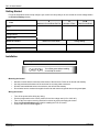
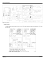
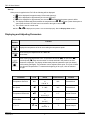
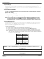
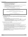
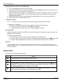
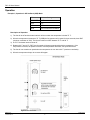
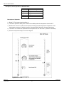
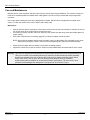
FHC-1D User Manual
Features
•
•
•
•
•
•
•
•
•
•
•
•
•
•
Non-corrosive, fire retardant, moisture resistant enclosure
Transient protected to ensure reliability
Microprocessor-based
Digital display of temperature, alerts and settings
Variable speed with adjustable differential
Idle Set mode with adjustable idle speed
Automatic shut-off mode (Off Set-Back) with adjustable
shut-off temperature
Three second full power turn on to minimize fan motor ice-up
Switch selectable for 115V AC or 230V AC operation
115/230V AC @ 10 Full Load Amps output for variable speed
fans (with RFI noise suppressor)
Compact design: 20cm (7.75in) height x 12cm (4.75in) width
x 9.5cm (3.75in) depth
Extendable temperature sensor
Heater interlock to signal gas-fired furnace, or power contactors
for electric heat
Two year limited warranty
Electrical Ratings
OPERATING VOLTAGE:
115V/230V AC, 60Hz
VARIABLE SPEED OUTPUT:
10 Full Load Amps @ 115/230V AC
Warning: Variable speed fan motors draw more current at reduced speeds than maximum speed. Fan motor
specifications show current draw at maximum speed. Current over 10 Amps will cause overheating and
eventual failure of the FHC-1D control. Please check current requirements for the fan motor by either
measuring current draw at all speeds or consulting the dealer for information on that fan.
The heater interlock output is a normally open relay contact. Use power contactors (not supplied) for electric heat or
heat lamps. Connect directly for most gas furnaces.
HEATER INTERLOCK OUTPUT:
10 Full Load Amps @ 115/230V AC
Warning: When connecting to electric heaters or brooder lamps and a furnace, operation voltages
may be different. This may damage the equipment.
Introduction
Congratulations on the purchase of your new FHC-1D environment control! The FHC-1D is a microprocessor-based
control that connects to a variable speed fan and a heater to efficiently control temperature. This manual will help you
get the most from your FHC-1D. Take a few minutes to read this manual and become familiar with the proper safety
and operating procedures. Follow the Getting Started section for step by step instructions on installing your FHC-1D.
Phason Inc.
111407 Rev. 4
2001-02-05
1
FHC-1D User Manual
Getting Started
Fill out the information below to help configure your control and verify that you do not exceed the current ratings listed in
the Electrical Ratings section.
A
Maximum Current Draw Per Fan
Fans
B
Number of Fans
A×B
Total Current Draw
Make:
Model:
Voltage Rating:
Power Factor:
Heater or Furnace
Maximum Current Draw
Voltage Rating
Make:
Model:
Installation
Warning: The FHC-1D should be installed by a qualified electrician.
Mounting the Control
•
•
•
•
Mount the control with the knockouts at the bottom of the enclosure. Failure to do this will void warranty.
Use the knockouts at the bottom of the enclosure for mounting cable connectors.
DO NOT make additional holes in the enclosure; this will void the warranty.
Run all wires into the enclosure through the knockouts and connect all ground wires to the ground plate.
Wiring the Control
•
•
•
•
•
Phason Inc.
111407 Rev. 4
Turn off the power before doing any wiring.
Set the voltage switch to the correct position for the line voltage used (115 or 230V AC).
Take off the cover when removing electrical knockouts to prevent damaging the control.
Read the Electrical Ratings section before installing the FHC-1D control.
Connect the wires as shown Figure 1.
2001-02-05
2
FHC-1D User Manual
Figure 1: Wiring Diagram
Heater Interlock
The heater interlock turns a heater or furnace on or off. The relay contacts close when the temperature is 2°F below
the TEMP SET.
Figure 2: Heater Interlock Wiring Diagram
Phason Inc.
111407 Rev. 4
2001-02-05
3
FHC-1D User Manual
Temperature Probe
•
•
•
Connect the probe to the fast-on tabs.
Gently pull on the probe to extend it out of the enclosure.
Tighten the compression nut on the strain relief.
Extending the Sensor
•
•
•
•
•
You can extend the temperature sensor to suit your particular application. The maximum length of sensor
depends on the level of electrical noise. With proper installation, sensor lengths of up to 500 feet are possible.
To extend the sensor, use two wire, 18 AWG jacketed cable for a proper seal at the cable entry hole. We
recommend Belden # 9408, Alpha # 5052, or an equivalent.
Do not run the sensor cable next to other power cables or inside conduit.
When crossing other cables, cross at 90°.
For best results, solder all connections and apply heat shrink to insulate the wires.
Follow these steps to extend the sensor:
a) Turn the power off to the control.
b) Remove the four screws from the cover and lift the cover off.
c) Disconnect the sensor connectors from the fast-on tabs.
d) Cut the sensor cable approximately six inches from the connectors and pull the probe end of the sensor cable out
of the box.
e) Insert the extension wire into the box.
f)
Join the connector end of the sensor cable to one end of the extension wire and re-connect the cable to the faston tabs. Apply heat shrink or electrical tape to insulate the wires.
g) Run the extended sensor cable to the desired location.
h) Join the other end of the extension wire to the end of the sensor cable containing the probe. Apply heat shrink or
electrical tape to insulate the wires.
NOTE: If the unit operates erratically with the extended temperature sensor, try running the sensor on a different path
or shortening it. Ensure the sensor cable is not run beside other electrical wires or near electrical equipment.
Four Zone Averaging
The FHC-1D can monitor the temperature in four different zones. The control takes an average of the four
temperatures and operates according to the average temperature. To take advantage of this option, you must
connect four temperature sensors to the unit. See Figure 3 for wiring information.
Figure 3: Four Zone Averaging
Phason Inc.
111407 Rev. 4
2001-02-05
4
FHC-1D User Manual
Start-up
When power is applied to the FHC-1D the following will be displayed:
a) 88 will be displayed for approximately 0.25 seconds (start-up).
b) 00 will be displayed for approximately one second (self-test).
c) 60 will be displayed for approximately one second. 60 indicates that the power system is 60Hz.
d) The display will alternately flash between the temperature and PF. PF indicates a power interruption or
start-up has occurred. Click the front cover switch to the right to clear the PF.
e) The control is now in normal mode.
NOTE: If PD or PS is displayed, the probe is not connected properly. See the Display Alerts section.
Displaying and Adjusting Parameters
Switch
Position
Function
Displays the temperature of the air surrounding the temperature probe
Allows viewing and adjustment of the TEMP SET
Clears alerts
Allows viewing and adjustment of the Temperature Differential (di), Off Set-Back (oS),
and Idle Speed (id). Each time the switch is clicked and held in this position, the next
parameter is displayed. The display will alternately flash the parameter code (two letters)
and it's setting (two digits). The parameter can be adjusted at this point. The cycle will start
over after the last parameter. To restart at the beginning of the cycle, click the switch to
the right
Parameter
Code
Range
Factory Setting
Temperature Set Point
N/A
32 to 99°F
or
0 to 38°C
N/A
External Knob
Idle Speed
id
0 - 99%
N/A
External Knob
Temperature Differential
di
1 to 20°F
or
0.6 to 12°C
6 °F
Internal Trimmer
Off Set-Back
oS
0 to 16°F
or
0 to 9°C
5 °F
Internal Trimmer
°F / °C
-22 to 99°F
or
-30 to 38°C
°F
Internal Jumper
°F or °C
Phason Inc.
111407 Rev. 4
Location
2001-02-05
5
FHC-1D User Manual
Temperature Display
When the switch on the control is in the center position, the control displays the ambient temperature. The
temperature range is -22 to 99°F or -30 to 38°C. The control can maintain the temperature to between 32 to 99°F
or 0 to 38 °C
Temperature Set Point (TEMP SET)
The TEMP SET is the desired temperature. It is also the reference for the Off Set-Back (OSB) and Temperature
Differential (DIFF) settings.
To display and adjust the TEMP SET:
a) Hold the switch in the set (right) position.
b) Adjust the Temperature knob to the desired setting.
NOTE: You must hold the switch in the set position while turning the Temperature knob. If this is not done
correctly, the display will flash between tS and temperature, indicating the Temperature knob has
accidentally been turned. The control will not accept the new setting until the switch is clicked to the right.
Temperature Differential (DIFF):
The DIFF is the number of degrees Celsius or Fahrenheit above the TEMP SET that the fan reaches maximum
speed. For example, if the TEMP SET is 80°F and the DIFF is 6°F, the fan will increase from IDLE at 80°F to
maximum speed at 86°F. See Figures 4 and 5 for examples.
To display and adjust the DIFF:
a) Click the switch to the right to start at the beginning of the parameter list.
b) Click the switch to the left once and hold. The display will flash between di and the setting.
c) Use a small flat screwdriver to adjust the internal trimmer. See Figure 1, section B for trimmer location.
NOTE: The difference in motor power factors can cause the actual differential to be less than the displayed
value. If the power factor of the motor is available, use the correction numbers and formula listed below
to calculate the correct DIFF setting.
Power Factor
Correction (°°F)
1.0
1.00
0.9
1.05
0.8
1.10
0.7
1.25
0.6
1.33
0.5
1.60
Actual DIFF = Desired DIFF X Correction
Example 1: To have an actual differential of 6°F with a motor that has a power factor of 0.7, set the DIFF to 7.5°F.
6°F x 1.25 = 7.5°F
Example 2: To have an actual differential of 5°F with a motor that has a power factor of 0.5, set the DIFF to 8.0°F.
5°F x 1.6 = 8.0°F
Phason Inc.
111407 Rev. 4
2001-02-05
6
FHC-1D User Manual
If you do not know the power factor, measure the correction as follows:
a) Ensure the IDLE is set properly (See IDLE section).
b) Set the DIFF to 10°F with the internal trimmer.
c) Observe the temperature (in the digital display).
d) Hold the switch to the right and adjust the TEMP SET to equal the temperature. The fan will operate just
above minimum Idle.
e) Slowly decrease the TEMP SET and listen to the fan increase in speed.
f) When the motor reaches full speed, record the TEMP SET (FULL SPEED TEMP SET).
g) Calculate the correction using the formula below.
Correction = 10°F ÷ (FULL SPEED TEMP SET- TEMPERATURE)
Example 3: For a TEMPERATURE of 75°F and a FULL SPEED TEMP SET of 82°F
The correction would be: 10°F ÷ (82°F-75°F) = 1.43
If the desired differential is 5°F, the actual differential can be calculated as follows:
5°F x 1.43 = 7.15°F.
Set the DIFF to 7°F for an actual differential of 5°F.
Off Set-Back/IDLE SET Mode (OSB)
The OSB is the number of degrees Celsius or Fahrenheit below the TEMP SET that the fan will switch between
OFF and IDLE. IDLE mode provides minimum ventilation at temperatures below the TEMP SET. See Figure 4 for
example of OSB.
To display and adjust the OSB:
a) Click the switch to the right to start at the beginning of the parameter list.
b) Click the switch to the left two times and hold. The display will flash between oS and the setting. If id is
displayed, the control is in IDLE SET mode.
c) Use a small flat screwdriver to adjust the internal trimmer to the desired OSB or turn the trimmer fully
clockwise to put the control into IDLE SET mode. See Figure 1, section C for trimmer location.
Adjusting Minimum Ventilation in OSB Mode
NOTE: A temperature probe must be connected to the control to adjust the IDLE properly.
a) Turn the Idle Speed knob fully counter-clockwise, then back ¼ turn clockwise.
b) Click the front cover switch to the right and hold while turning the Temperature knob fully clockwise, then
release the switch. The fan should not be running
c) Click the front cover switch to the right and hold while slowly turning the Temperature knob counterclockwise. When the fan runs full speed, release the front cover switch and the Temperature knob. The fan
will run at maximum speed for approximately three seconds, then at IDLE. The Temperature knob should
be approximately 1°F higher than the temperature.
d) Slowly adjust the Idle Speed knob until a satisfactory IDLE (minimum ventilation) is reached. A voltmeter is
helpful for determining the voltage. If you are unsure, please consult your fan dealer for the minimum idle
voltage for your fan motor.
e) Click the front cover switch to the right and adjust the Temperature knob to the desired temperature.
f) Release the switch to complete the procedure.
Phason Inc.
111407 Rev. 4
2001-02-05
7
FHC-1D User Manual
Adjusting Minimum Ventilation in IDLE SET Mode
a) Turn the Idle Speed knob fully counter-clockwise.
b) Click the front cover switch to the right and hold while turning the Temperature knob fully clockwise, then
release the switch. The fan should be running at IDLE.
c) Slowly adjust the Idle Speed knob until a satisfactory IDLE (minimum ventilation) is reached. A voltmeter is
helpful for determining the voltage. If you are unsure, please consult your fan dealer for the minimum idle
voltage for your fan motor.
d) Click the front cover switch to the right and adjust the Temperature knob to the desired temperature.
e) Release the switch to complete the procedure.
Temperature Display
The °F / °C jumper lets you select whether the control will display degrees Fahrenheit or Celsius.
To verify the °F / °C setting:
a) Click the front cover switch to the right to start at the beginning of the parameter list.
b) Click the switch to the left three times. °C or °F will be displayed.
c) To change the setting, position the jumper as shown in Figure 1, section D.
Idle Speed (IDLE)
The IDLE is the speed of the fan in IDLE SET mode. IDLE is displayed as a percentage of maximum speed. See
Figures 4 and 5 for examples.
To display and adjust the IDLE:
a) Click the switch once to the right to start at the beginning of the parameter list.
b) Click the switch to the left four times and hold. The display will alternately flash between id and the setting.
c) Adjust the Idle Speed knob on the front cover to the desired fan speed (minimum ventilation).
Hysteresis
The FHC-1D has a 1°F (0.5°C) hysteresis. This means the fan will turn off 1°F below the point it turned on. For
example, if TEMP SET is 75°F, the fan will turn on at 75°F, off at 74°F. This prevents the fan from flickering on and
off at the TEMP SET.
Display Alerts
The FHC-1D has several visible display alerts:
Display
Cause
PS
The temperature probe or sensor cable has short circuited.
PD
The temperature probe is damaged or the connecting wire is broken.
tS
The Temperature knob has accidentally been turned. The display will alternately flash tS and the
temperature. The control will not accept the new setting until the switch is clicked to the set position. See
the Temperature Display section on page 5 for more details.
PF
The power has been interrupted. The display will flash between PF and the temperature. To clear the
alarm, click the switch to the right. The control will function normally.
Phason Inc.
111407 Rev. 4
2001-02-05
8
FHC-1D User Manual
Operation
Example 1, Operation in Off Set-Back (OSB) Mode
Parameter
Settings
TEMP SET
80°F
DIFF
6°F
OSB
5°F
IDLE
20% of maximum ventilation
Description of Operation
1) The fan will be off and the heater interlock will be on when the temperature is below 75°F.
2) When the temperature increases to 75°F (OSB) the fan operates at full speed for three seconds, then IDLE
(minimum ventilation of 20%). The fan will continue to IDLE between 75°F and 80°F.
3) At 78°F the heater interlock shuts off.
4) Between 80°F and 86°F (DIFF) the fan speed will change proportionally with the temperature. If the
temperature increases, fan speed increases. If the temperature decreases, fan speed decreases.
5) The fan will run at maximum speed when the temperature is at or above 86°F (maximum ventilation).
6) When the temperature drops, the reverse will happen.
Figure 4: Off Set-Back Mode
Phason Inc.
111407 Rev. 4
2001-02-05
9
FHC-1D User Manual
Example 2, Control Operation in IDLE SET Mode
Parameter
Settings
TEMP SET
80°F
DIFF
6°F
OSB
OFF
IDLE
20% of maximum ventilation
Description of Operation
1) Below 78°F the heater interlock will be on.
2) The fan will operate at IDLE (20% of maximum ventilation) when the temperature is below 80°F.
3) Between 80°F and 86°F (DIFF) the fan speed will change proportionally with the temperature. If the
temperature increases, fan speed increases. If the temperature decreases, fan speed decreases.
4) The fan will run at maximum speed when the temperature is at or above 86°F (maximum ventilation).
5) When the temperature drops, the reverse happens.
Figure 4: IDLE SET Mode
Phason Inc.
111407 Rev. 4
2001-02-05
10
FHC-1D User Manual
Care and Maintenance
Moisture will not cause a problem with the control if proper care is taken during installation. The control's enclosure is
made of fire retardant plastic and sealed with a rubber gasket. The sensor entry is sealed with a liquid tight cable
connector.
Use caution when washing the room with a high-pressure washer. DO NOT direct a high-pressure washer at the
control. To clean the surface of the control, wipe it with a damp cloth.
Maintenance
•
•
•
After the first two weeks of operation, remove the cover from the unit and check inside for moisture. Be sure to
turn off the power to the control before removing the cover.
If moisture is present, wipe the control out with a dry cloth. Check the cable entry points and rubber gasket for
proper sealing.
If the cable connectors are not sealing, apply RTV or Silicon II sealant around the cable.
NOTE: Some silicone sealants release acetic acid while curing. Let the sealant cure completely (one to three
days) before closing the control. Failure to do this may damage the control and void the warranty.
•
•
Check the control again after two weeks to verify that it is sealing properly.
Inspect the control once a year for moisture. Proper care and maintenance will extend the life of the control.
Warning: This control is designed and manufactured to provide reliable performance but is not guaranteed to be
100% free of defects. Even reliable products may experience occasional failures and this possibility
should be recognized by the user. If this product is used in a life support ventilation system where
failure could result in loss or injury, the user should provide adequate back-up ventilation,
supplementary natural ventilation or an independent failure alarm system. The user's lack of such
precautions acknowledges their willingness to accept the risk of such loss or injury.
Phason Inc.
111407 Rev. 4
2001-02-05
11
FHC-1D User Manual
LIMITED WARRANTY
PHASON warrants this unit, the FHC-1D, subject to the following terms and conditions. This warranty is valid only to the
original purchaser for a period of two years from the date of manufacturing. The manufacturing date is stated in the first
eight digits of the serial number in the form year-month-day. PHASON hereby warrants that should this product prove
defective by reason of improper workmanship, PHASON will repair the unit, effecting all necessary parts replacements
without charge for either parts or labour.
CONDITIONS
1. Installation must be made in accordance with our enclosed installation instructions.
2. The unit must not have been previously altered, modified or repaired by anyone other than PHASON.
3. The unit must not have been subject to accident, misuse, abuse or operated or installed contrary to the
instructions contained in the accompanying manual. The opinion of PHASON with respect to these matters
shall be final.
4. The person requesting the services provided hereunder must be the original purchaser of the unit and furnish
proof of purchase upon request.
5. This warranty is applicable only to the PHASON FHC-1D Temperature Control.
6. All transportation charges on units submitted for warranty repair must be borne by the purchaser.
7. For warranty services, return unit together with original proof of purchase to your dealer.
EXCEPT TO THE EXTENT PROHIBITED BY APPLICABLE LAW, NO OTHER WARRANTIES, WHETHER EXPRESSED
OR IMPLIED, INCLUDING WARRANTIES OF MERCHANTABILITY AND FITNESS FOR A PARTICULAR PURPOSE,
SHALL APPLY TO THIS UNIT. ANY AND ALL IMPLIED WARRANTIES ARE EXCLUDED. PHASON SHALL NOT BE
LIABLE FOR CONSEQUENTIAL DAMAGES SUSTAINED IN CONNECTION WITH THE SAID UNIT. PHASON NEITHER
ASSUMES NOR AUTHORIZES ANY REPRESENTATIVES OR OTHER PERSONS TO ASSUME FOR IT ANY
OBLIGATION OR LIABILITY OTHER THAN SUCH AS IS EXPRESSLY SET FORTH HEREIN.
PHASON reserves the right to improve or alter the FHC-1D without notice.
Phason Inc.
2 Terracon Place
Winnipeg, Manitoba, Canada
R2J 4G7
Phone:
204-233-1400
Fax:
204-233-3252
111407 Rev. 4
2001-02-05
12