1
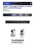
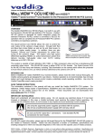
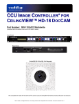
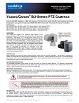
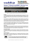
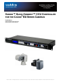
Installation and User Guide
Cameras and Controllers
For Integrators
VADDIO™ QUICK-CONNECT™ CCU CONTROLLER
®
FOR THE CANON BU SERIES CAMERAS
Part Numbers:
999-4190-000 (North America)
999-4190-001 (International)
©2010 Vaddio - All Rights Reserved. Quick-Connect CCU for Canon BU Series Cameras Installation and User Guide 342-0152 Rev. A
Quick-Connect CCU Controller for Canon BU Series Cameras
Quick-Connect CCU Controller for the Canon BU Series Cameras
Front Panel
Rear Panel
Overview:
The Vaddio Quick-Connect CCU Controller for the Canon BU Series PTZ Cameras (above) allows the discerning
video professional to control the color and shading of the BU Series camera’s video output. A host of advanced
controls are available to accurately and precisely set up a video shoot even in the most challenging environments.
The Quick-Connect CCU Controller is different from Vaddio’s previous CCU offerings in that it does not process
the HD-SDI video from the camera output ensuring the video quality and signal integrity of the BU camera.
Instead, it controls the camera’s DSP functions and provides the most advanced image control available today.
The Quick-Connect CCU Controller is equipped with Control IN and OUT and can be run in-line with the Vaddio
ProductionVIEW HD-SDI video mixer/switcher or the ProductionVIEW Precision Camera Controller. Using the
Vaddio Cat. 5e Structured Media Control Cabling Standard, the control signals can be routed over Cat. 5e (or Cat.
6) up to the distance of 500’ (152.4 m).
The Quick-Connect has many useful features including tally illumination on the front panel which allows the
operator to know exactly which camera and CCU is live, a variety of auto and manual modes including night
mode, and the ability to store scenes for time of day programming and baseline shot set-ups.
Intended Use:
Before operating the system, please read the entire manual thoroughly. The system was designed, built and
tested for use indoors, and with the provided power supply. The use of a power supply other than the one
provided or outdoor operation has not been tested and could damage the camera and/or create a potentially
unsafe operating condition.
Save These Instructions:
The information contained in this manual will help you install and operate your system. If these instructions are
misplaced, Vaddio keeps copies of Specifications, Installation, User Guides and the most pertinent product
drawings on the Vaddio website. These documents can be downloaded from www.vaddio.com free of charge.
Important Safeguards:
Read and understand all instructions before using. Do not operate any device if it has been dropped or damaged.
In this case, a Vaddio technician must examine the product before operating. To reduce the risk of electric shock,
do not immerse in water or other liquids and avoid extremely humid conditions.
Use only the power supply provided with the Quick-Connect System.
Use of any unauthorized power supply will void any and all warranties.
Please do not use “pass-thru” type RJ-45 connectors. These pass-thru type connectors
do not work well for professional installations and can be the cause of intermittent
connections which can result in the camera control line failing and locking up. For best
results please use standard RJ-45 connectors and test all cables for proper pin-out prior
to termination.
Quick-Connect CCU for Canon BU Series Cameras - Installation and User Guide 342-0152 Rev. A
Page 2 of 8
Quick-Connect CCU Controller for Canon BU Series Cameras
Unpacking:
Carefully remove all of the parts from the shipping box. Unpack and identify the following parts for the QuickConnect CCU Controller Packages Listed Below:
Canon BU Series CCU (North America)
Part Number 999-4190-000
• One (1) Vaddio Quick-Connect CCU for BU Series (998-1105-021)
• One (1) 12VDC, 1.0 Amp PowerRite Power Supply & US Power Cord
• One (1) User Manual
Note: Canon BU Series Camera Not Included
Canon BU Series CCU (International)
Part Number 999-4190-001
• One (1) Vaddio Quick-Connect CCU for BU Series (998-1105-021)
• One (1) 12VDC, 1.0 Amp PowerRite Power Supply
• One (1) AC Cord Set for EURO
• One (1) AC Cord Set for UK
• One (1) User Manual (
Note: Canon BU Series Camera Not Included
Quick-Connect CCU Front Panel Features and Controls (from left to right):
1. Tally Light:
The blue LED tally light on the front panel is tied to the tally contacts on the rear panel allowing the user to
easily track which CCU and camera is live in a multi-camera system by supplying a simple contact closure.
2. LCD Backlit Display:
Blue backlit display indicates which mode is active (CCU Control or Bypass for PTZ control). In CCU
CONTROL mode, when a rotary encoder is touched, the name of the control being actuated and the value of
that assigned parameter will be displayed.
Front Panel Controls Magnified:
3. CCU Control/Bypass Off Switch:
Blue backlit switch, lit when activated, blocks the incoming PTZ controls on the RS-232 input and allows the
end user to make adjustments to the camera image characteristics. When off or deactivated, PTZ information
is throughput to the camera and the front panel controls of the CCU are deactivated to avoid a control issue or
latency created by a master control string filtering program.
4. Scene A and B:
Two camera adjustment scenes can be stored in the CCU. When illuminated, the scene is activated. To
store a scene, the user adjusts the camera to taste and touches and holds the scene button down until the
button blinks.
Quick-Connect CCU for Canon BU Series Cameras - Installation and User Guide 342-0152 Rev. A
Page 3 of 8
Quick-Connect CCU Controller for Canon BU Series Cameras
Front Panel Controls (continued)
5. Gamma or Horizontal Detail:
Gamma adjusts the mid-range brightness of an image. Horizontal Detail sharpens or softens objects
captured. Both gamma and horizontal detail are available in manual mode only.
6. Black Gain or Color Matrix:
Black Gain adjusts the black levels of objects. Color matrix adjusts the overall color expression during
shooting. Both adjustments are available in manual mode only
7. Knee Point or Hue:
Knee point allows bright objects that are easily overexposed, such as background objects visible through
windows when shooting inside, to be reproduced more accurately. Hue allows the tint adjustment of the
entire image on the screen. Both knee point and hue are adjustable in manual mode only.
8. Shift Switch:
Allows the activation of either the top line controls or the bottom line controls. When the Shift is not lit, then
the knobs control the top line of controls and when Shift is lit then the bottom line of controls are active.
9. AWB:
Auto White Balance Mode controls/adjusts the color levels automatically when engaged. Turn off AWB to
manually adjust the Red and Blue levels.
10. Master Gain or Image Stabilization:
Master Gain increases the overall signal level in situations when the iris is open all the way but there is not
enough available light. Image stabilization is used to reduce blur in the video image resulting from the
camera being mounted high on a pole or other locations susceptible to vibrations or movement.
11. Red Gain or ND Filter:
Red gain adjusts the red shading of the overall image and is available in manual mode only. ND (neutral
density) filter is used outdoors, typically under clear skies, to allow the user to open the iris up to a higher Fstop and is available for use in either auto or manual modes.
12. Blue Gain or Shutter:
Blue gain adjusts the blue shading of the overall image and is available in the manual mode only. Shutter
allows the user to regulate the exposure and maintain desired motion portrayal. Keep the shutter at 1/60 or
1/100 to prevent strobe or flicker when shooting under fluorescent, mercury vapor or halogen lamps. Shutter
is only available in manual mode.
13. Auto Mode:
Auto mode allows the user to adjust only the ND Filter and Image Stabilization on the CCU. All other
functions are automatically adjusted in this mode. In addition, the Digital Extender is available when using the
Vaddio Precision Camera Controller by pressing the button on top of the joystick.
14. Iris Control:
Iris control allows the user to manually set the amount of light hitting the image sensors when the camera is in
manual mode.
15. Master Pedestal:
Increases or decreases the overall image lightness or darkness when the camera is in the manual mode.
Quick-Connect CCU for Canon BU Series Cameras - Installation and User Guide 342-0152 Rev. A
Page 4 of 8
Quick-Connect CCU Controller for Canon BU Series Cameras
Rear Panel Controls and I/O (from left to right):
1. Power Supply Input:
12 VDC 1.0 Amp Power Supply Input on a 5.5mm OD x 2.5mm ID connector.
2. RS-232 IN on RJ-45:
RS-232 Input from ProductionVIEW or PTZ controller. Daisy Chain control is not supported.
3. RS-232 OUT on RJ-45:
RS-232 on RJ-45 provides for bi-directional control to the camera.
4. Tally on 2-pin Phoenix-type connector:
Contact closure illuminates the LED on front panel allowing indication of which CCU/camera combination is
active in a multi-camera/CCU installation.
5. Camera Settings Dip Switch:
The CCU Controller has an 8-position dip switch on the rear panel to allow for different modes of functionality
and future functionality. For the Canon BU Series cameras, Dip Switch #3 should be in the UP position
and all other switches should be in the down position.
Basic System Connectivity Examples:
• BU-50/51 with Quick-Connect CCU Controller and ProductionVIEW HD-SDI Console
RS-232
Quick-Connect CCU
RS-232
Adapter
HD-SDI
Canon
BU-50/51
ProductionVIEW HD-SDI
•
BU-45/46 with Quick-Connect CCU Controller and ProductionVIEW Precision Camera Controller
RS-232
Quick-Connect CCU
RS-422
Adapters
RS-232
HD-SDI
To Switcher
ProductionVIEW Precision Camera Controller
Quick-Connect CCU for Canon BU Series Cameras - Installation and User Guide 342-0152 Rev. A
Canon
BU-45/46
Page 5 of 8
Quick-Connect CCU Controller for Canon BU Series Cameras
Compliance and CE Declaration of Conformity - Quick-Connect CCU Controller
FCC Part 15 Compliance
This equipment has been tested and found to comply with the limits for a Class A digital device, pursuant to Part
15 of the FCC Rules. These limits are designed to provide reasonable protection against harmful interference
when the equipment is operated in a commercial environment. This equipment generates, uses, and can radiate
radio frequency energy and, if not installed and used in accordance with the instruction manual, may cause
harmful interference to radio communications. Operation of this equipment in a residential area is likely to cause
harmful interference in which case the user will be required to correct the interference at his/her own expense.
Operation is subject to the following two conditions: (1) This device may not cause interference, and (2) This
device must accept any interference including interference that may cause undesired operation of the device.
Changes or modifications not expressly approved by Vaddio can affect emission compliance and could void the
user’s authority to operate this equipment.
ICES-003 Compliance
This digital apparatus does not exceed the Class A limits for radio noise emissions from digital apparatus set out
in the Radio Interference Regulations of the Canadian Department of Communications.
Le présent appareil numérique n’emet pas de bruits radioélectriques dépassant les limites applicables aux
appareils numeriques de la classe A préscrites dans le Règlement sur le brouillage radioélectrique édicte par le
ministère des Communications du Canada.
European Compliance
This product has been evaluated for Electromagnetic Compatibility under the EMC Directive for Emissions and
Immunity and meets the requirements for a Class A digital device. In a domestic environment this product may
cause radio interference in which case the user may be required to take adequate measures.
Standard(s) To Which Conformity Is Declared:
EMC Directive 89/336/EEC
EN 55022A: September 1998, A1 October 2000 - Conducted and Radiated Emissions
EN 55024: 1998 + Amendment A1: 2001 - Electromagnetic Compatibility - Immunity
EN 61000-4-2
Electrostatic Discharge Requirements
EN 61000-4-3
Radiated Electromagnetic Field Requirement
EN 61000-4-4
Electrical Fast Transients / Burst Requirements
EN 61000-4-5
Surge Requirements
EN 61000-4-6
Conducted Immunity Requirements
EN 61000-4-8
Power Frequency Magnetic Field Requirements
EN 61000-4-11
Voltage Dips, Interrupts and Fluctuations Requirements
Quick-Connect CCU for Canon BU Series Cameras - Installation and User Guide 342-0152 Rev. A
Page 6 of 8
Quick-Connect CCU Controller for Canon BU Series Cameras
WARRANTY INFORMATION (See Vaddio Warranty Policies posted on vaddio.com for complete details):
Hardware* Warranty - One year limited warranty on all parts. Vaddio warrants this product against defects in materials and
workmanship for a period of one year from the day of purchase from Vaddio. If Vaddio receives notice of such defects during
the warranty period, they will, at their option, repair or replace products that prove to be defective.
Exclusions - The above warranty shall not apply to defects resulting from: improper or inadequate maintenance by the
customer, customer applied software or interfacing, unauthorized modifications or misuse, operation outside the normal
environmental specifications for the product, use of the incorrect power supply, improper extension of the power supply cable
or improper site operation and maintenance.
Vaddio Customer Service – Vaddio will test, repair, or replace the product or products without charge if the unit is under
warranty and is found to be defective. If the product is out of warranty, Vaddio will test then repair the product or products. The
cost of parts and labor charge will be estimated by a technician and confirmed by the customer prior to repair. All components
must be returned for testing as a complete unit. Vaddio will not accept responsibility for shipment after it has left the premises.
Vaddio Technical Support - Vaddio technicians will determine and discuss with the customer the criteria for repair costs
and/or replacement. Vaddio Technical Support can be contacted through one of the following resources: e-mail support at
[email protected] or online at www.vaddio.com.
Return Material Authorization (RMA) Number - Before returning a product for repair or replacement, request an RMA from
Vaddio’s technical support. Provide a technician with a return phone number, e-mail address, shipping address, and product
serial numbers and describe the reason for repairs or returns as well as the date of purchase and proof of purchase. Include
your assigned RMA number in all correspondence with Vaddio. Write your assigned RMA number on the outside of the box
when returning the product. All returns are subject to a restocking fee (see warranty policies at vaddio.com).
Voided Warranty – The warranty does not apply if the original serial number has been removed or if the product has been
disassembled or damaged through misuse, accident, modifications, or unauthorized repair. Cutting the power supply cable on
the secondary side (low voltage side) to extend the power to the device (camera or controller) voids the warranty for that
device.
Shipping and Handling - Vaddio will not pay for inbound shipping transportation or insurance charges or accept any
responsibility for laws and ordinances from inbound transit. Vaddio will pay for outbound shipping, transportation, and
insurance charges for all items under warranty but will not assume responsibility for loss and/or damage by the outbound
freight carrier. If the return shipment appears damaged, retain the original boxes and packing material for inspection by the
carrier. Contact your carrier immediately.
Products Not Under Warranty - Payment arrangements are required before outbound shipment for all out of warranty
products.
*Vaddio manufactures its hardware products from parts and components that are new or equivalent to new in accordance with industry standard practices.
Other General Information:
Care and Cleaning
Do not attempt to take this product apart at any time. There are no user-serviceable components inside.
•
Do not spill liquids or liquid type substances onto the device.
•
Keep this device away from food or liquid.
•
For smears or smudges on the devices, wipe with a clean, soft cloth.
•
Do not use any abrasive pads or caustic chemicals at any time on any Vaddio equipment.
Operating and Storage Conditions:
Do not store or operate the device under the following conditions:
•
Temperatures above 40°C (104°F) or temperatures below 0°C (32°F)
•
High humidity, condensing or wet environments
•
In inclement weather
•
Dusty environments
•
In a swimming pool
•
Dry environments with an excess of static discharge
•
In outer space
•
Under severe vibration
Quick-Connect CCU for Canon BU Series Cameras - Installation and User Guide 342-0152 Rev. A
Page 7 of 8
Quick-Connect CCU Controller for Canon BU Series Cameras
9433 Science Center Drive, Minneapolis, MN 55428
Toll Free: 800-572-2011 ▪ Phone: 763-971-4400 ▪ FAX: 763-971-4464
www.vaddio.com
©2010 Vaddio - All Rights Reserved. Reproduction in whole or in part without written permission is prohibited. Specifications and pricing are subject to change
without notice. Vaddio, Quick-Connect, EZCamera, ProductionVIEW and PowerRite are registered trademarks of Vaddio. All other trademarks are property of
Quick-Connect
for Canon
BU Series
Cameras
Page 8 of 8
their respective
owners. CCU
Document
Number
342-0152
Rev. A- Installation and User Guide 342-0152 Rev. A