1
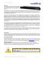
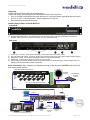
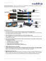
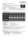
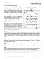
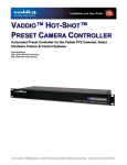
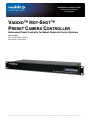
Installation and User Guide
Cameras and Controllers
For Integrators
VADDIO™ HOT-SHOT™
PRESET CAMERA CONTROLLER
Automated Preset Controller for Select Codecs & Control Systems
Part Numbers:
999-1036-000 North America
999-1036-001 International
©2011 Vaddio - All Rights Reserved. Hot-Shot Preset Camera Controller Installation and User Guide Document Number 342-0124 Rev. B
Hot-Shot Preset Camera Controller
Hot-Shot Preset Camera Controller - Installation and User Guide 342-0124 Rev. B
Page 2 of 12
Hot-Shot Preset Camera Controller
Overview:
The Hot-Shot Preset Camera Controller is part
of the Vaddio Automated Content Presentation
System products and is truly as simple as it is
elegant.
The Hot-Shot has 36 preset trigger inputs and can automate any classroom or presentation environment using
select codecs or control systems in conjunction with Vaddio’s preset camera trigger devices such as MicVIEW™
Mic Mixer/Switcher, StepVIEW™ Mats, AutoVIEW™ IR Sensors, PresenterPOD™, TouchVIEW™ as well as
other triggering/logic output devices.
The Hot-Shot will accept a trigger input from a trigger device, for example, a mat on Trigger 2. When the mat is
triggered by a presenter standing on it, the Hot-Shot will output “PRESET 2” in the RS-232 protocol of the
assigned codec and then the camera and preset (pan/tilt/zoom coordinates) associated with Preset 2 for that
codec will be activated. Trigger 3 will output “Preset 3” over RS-232; Trigger 4 will output “Preset 4” and so on.
The Hot-Shot does not store presets, but merely outputs the codec’s control protocol to activate the presets
stored in the codec. The Hot-Shot can be cascaded up to 144 triggers, using 4 Hot-Shots linked via RS-232 for
even the largest interactive videoconferencing environment applications using microphones or a variety of other
trigger devices.
Currently, the Hot-Shot has the Polycom® HDX-8000 and HDX-9000 series preset recall commands, LifeSize®
Room System preset commands, TANDBERG C40, C60 and C90 series preset recall commands, and even the
older TANDBERG 6000MXP and 3000MXP commands are also included. For use with other control systems,
the Vaddio simple ASCII API is also included to alleviate the need for multiple I/O or relay cards/boxes
associated with large control systems that require many trigger inputs.
The Vaddio Hot-Shot Preset Camera Controller is an outstanding and super easy to operate codec camera
control system or control system addition. Applications for the Hot-Shot include videoconferencing, distance
education, participative auditoriums, local government and council meetings.
.
Intended Use:
Before operating the system, please read the entire manual thoroughly. The system was designed, built and
tested for use indoors, and with the provided power supply. The use of a power supply other than the one
provided or outdoor operation has not been tested and could damage the camera and/or create a potentially
unsafe operating condition.
Save These Instructions:
The information contained in this manual will help you install and operate your system. If these instructions are
misplaced, Vaddio keeps copies of Specifications, Installation, User Guides and the most pertinent product
drawings on the Vaddio website. These documents can be downloaded from www.vaddio.com free of charge.
Important Safeguards:
Read and understand all instructions before using. Do not operate any device if it has been dropped or
damaged. In this case, a Vaddio technician must examine the product before operating. To reduce the risk of
electric shock, do not immerse in water or other liquids and avoid extremely humid conditions.
Use only the 12 VDC, 1.0 Amp power supply provided with the
product. Use of any unauthorized power supply will void any
and all warranties.
Hot-Shot Preset Camera Controller - Installation and User Guide 342-0124 Rev. B
Page 3 of 12
Hot-Shot Preset Camera Controller
Unpacking:
Carefully remove all of the parts from the shipping box.
Unpack and identify the following parts for the Hot-Shot Preset Camera Controller:
• One (1) Hot-Shot Preset Camera Controller with three (3) 14-position Phoenix type spring cage connectors
• One (1) 12 VDC, 1.0 Amp PowerRite™ Power Supply with AC Cord Set
• Documentation (User Manual 342-0124)
Hot-Shot Preset Camera Controller Basic I/O:
Front Panel
①
1) Power/Preset Enable Switch: To bypass presets, touch the Power switch, LED light off indicates the presets are
disabled. When power is connected to the system, the blue LED will illuminate.
Rear Panel
②
①
1)
2)
3)
4)
5)
④
③
⑤
Power Input - 12 VDC, 1.0 Amp Power Connection, 5.5mm OD x 2.5mm ID, Positive Center
Thirty Six (36) Trigger Inputs: Triggers on phoenix-type connectors with six (6) ground pins to support multiple triggers
RS-232 Ext. Control: For Hot-Shot cascading and external control system feed-thru
RS-232 Out: Preset # ASCII strings out to codec or control system
System Select: 10-position dip switch selects output preset codes, first or last step trigger modes, assign Preset 1 as
default preset and master/slave cascade functionality
Basic Connectivity: Basic Classroom Configuration featuring the Hot-Shot and TANDBERG C60 Codec (Far
End camera control retained)
Vaddio MicVIEW Mic Mixer/Switcher
AutoVIEW
IR Sensor
Push to
Talk
Student
Mics
StepVIEW Mat
Teacher’s
Location
Preset
Triggers
HOT-SHOT Preset Camera Controller
Audio
Audio
RS-232
Preset #’s
RGBHV
PC
T C60 Codec
LAN
DVI/HDMI
Monitor 1
DVI/HDMI Video
RS-232
Monitor 2
Daisy
Chain RS-232
Student
Camera
HD Monitors - Simulated Video Feed
PrecisionHD
Cameras
Hot-Shot Preset Camera Controller - Installation and User Guide 342-0124 Rev. B
Instructor
Camera
Page 4 of 12
Hot-Shot Preset Camera Controller
Advanced Connectivity: Three (3) Hot Shots, Six (6) MicVIEWs, PresenterPOD, AutoVIEW IR Sensor,
StepVIEW Mat w/Polycom Codec and External Control System
AutoVIEW IR
Sensor
StepVIEW Mat
PresenterPOD
System
External Control
System
Control
Six (6) MicVIEWs with
12 Mics Each (72 Total)
HOT-SHOT Preset Camera Controller 3
RS-232
Audio
Link
HOT-SHOT Preset Camera Controller 2
RS-232
HOT-SHOT Preset Camera Controller Master
Audio
PC
RS-232
NEAR END
FAR END
HD Video
EE PTZ
Camera
P-HDX Codec
Video & CTL
Video & CTL
Video & CTL
EE PTZ Camera
EE PTZ Camera
HD Monitors - Simulated Video Feed
Hot-Shot Key Features:
•
Each Hot-Shot can receive up to 36 physical trigger inputs from any trigger device.
For example; MicVIEW, AutoVIEW IR Sensor, StepVIEW Mats, TouchVIEW Buttons and PresenterPOD
(even paper clips too) can be used as triggers.
•
Up to 4 Hot-Shots can be cascaded together for a total of 144 trigger inputs.
While TANDBERG and LifeSize do not offer that many camera presets, the Polycom systems offer up to 99
camera positioning presets.
•
The Hot Shot outputs RS-232 commands (ASCII Control Strings) in the RS-232 protocol of the
selected codec including:
• TANDBERG C40, C60 and C90 series codecs
• TANDBERG 6000MXP, 3000MXP
• Polycom HDX-9000 and HDX-8000
• LifeSize Room Series Codecs (with RS-232 Port)
®
®
• Vaddio Generic (for use with Crestron or AMX Systems)
•
Flexible triggering modes are included.
The Hot-Shot can be set up as a “Last Step” or “First Step” triggering mode. Setting it up in Last Step Mode
allows for the last trigger activated to switch to that trigger’s preset. First Step trigger mode allows the first
trigger to activate and then prevent all other triggers until the first trigger is released.
•
Default Idle Return to Preset 1.
Default idle return to preset 1 allows the system to use Preset # 1 (Preset 0 in codecs that have presets that
start at 0) stored in the codec as the default camera shot when no triggers are present. This is especially
useful for a teacher’s or presenter’s position when setting up the room for teacher/student discussions.
Hot-Shot Preset Camera Controller - Installation and User Guide 342-0124 Rev. B
Page 5 of 12
Hot-Shot Preset Camera Controller
Setting Up the Hot-Shot Preset Camera Controller
The Dip Switches:
There are ten (10) dip switches on the rear panel that configure the Hot-Shot Preset
Camera Controller. Configuration is not automatic, but it is easy to understand. The
dip switches control the following functions:
Dip Switches 1 through 4:
Dip Switches 5 and 6:
Dip Switch 7:
Dip Switch 8:
Dip Switch 9 and 10:
Assigns the RS-232 output preset codes
Not used - for future features
Assigns the trigger processing order (Last Step or First Step)
Assigns Preset #1 to Default Idle Return (returns to preset #1 when no trigger on)
Sets the Hot-Shot Address and Master/Slave configuration when cascaded
The following table identifies the dip switch settings in detail. Set these switches according to the application
requirements of the installation.
Function / Dip Switch
Vaddio Default ASCII
Polycom Codecs
TANDBERG C-Series Codecs
TANDBERG MXP Codecs
LifeSize Codecs
Trigger Last Step
Trigger First Step
Default Idle Return to Preset 1
(Preset 0 on Polycom and
TANDBERG Codecs)
Idle Return Off
Hot-Shot Address Master 0
Hot-Shot Address Slave 1
Hot-Shot Address Slave 3
Hot-Shot Address Slave 4
SW1
Up
Down
Up
Up
Up
-
SW2
Up
Up
Down
Up
Up
-
SW3
Up
Up
Up
Down
Up
-
SW4
Up
Up
Up
Up
Down
-
SW5
-
SW6
-
-
-
-
-
-
-
-
-
-
-
-
-
SW7
Up
Down
-
SW8
-
SW9
-
SW10
-
-
-
Up
-
-
Down
-
Up
Up
Down
Down
Up
Down
Up
Down
Control Protocols and Strings:
When a preset number is triggered, for example Preset # 2*, the ASCII Output Strings are automatically output
in the following formats:
• Vaddio Default ASCII:
Preset 2<cr><lf>
• Polycom:
preset near go 3<cr><lf>
• TANDBERG C-Series:
xcommand preset activate presetid:3<cr><lf>
• TANDBERG MXP Series:
presetactivate number:3<cr><lf>
set camera position -P 2<cr><lf>
• LifeSize**:
*For Polycom and TANDBERG codecs that have a Preset “0”, presets on the Hot-Shot are offset by -1 (1 = 0,
2 = 1, 3 = 2 and so on, for the codec preset).
**For LifeSize Codecs: The “0” key, when used as a preset, always moves the selected camera to the default
position and cannot be overwritten. There is no offset to the Hot-Shot and LifeSize preset numbers.
The Vaddio Default ASCII is squared off and there is no offset to the preset numbers.
Note: All commands are followed by a carriage return <cr> and line feed <lf>
Physical Connection:
The RS-232 connection between the Hot-Shot and the codec varies from codec to codec depending on the
manufacturer. The following RS-232 connections are required for proper operation:
• Hot-Shot to Polycom Codec:
9-Pin Female to Female Cable - Null Modem
• Hot-Shot to TANDBERG Codec:
9-Pin Female to Male Cable - Straight Through
• Hot-Shot to Life Size Codec:
9-Pin Female to Female Cable - Null Modem
Hot-Shot Preset Camera Controller - Installation and User Guide 342-0124 Rev. B
Page 6 of 12
Hot-Shot Preset Camera Controller
INSTALLATION Step-by-Step Example:
This example is a room system using a TANDBERG
C60 codec with two (2) cameras (student camera
located in front and the instructor camera in the rear of
the room). There are 18 students and 9 tables with two
students to a table and each table has a push to talk mic
(9 total mics) set to momentary mode. The microphone
mixer/switcher is the Vaddio MicVIEW. The instructor
has a front of the room lectern which will be a default
position and a whiteboard area that will be covered by a
Vaddio AutoVIEW IR Sensor. Monitors are at the front
of the room. The instructor has a mic at the lectern
position that is always on - or - has a wireless lapel mic
plugged into MicVIEW Input # 1 which is always on. The
equipment is in the lectern or small rack nearby.
Basic Hot-Shot Room Example
Student
Camera (1)
Whiteboard
(P2)
IR Sensor
Displays
Instructor
Position (P1)
Lectern
Mics x 10
P3
P4
P5
Step 1:
Install the videoconferencing system as described by the
system manufacturer.
P6
P7
P8
Step 2: With the codec IR remote control, set the preset
positions in the codec preset memory reflecting where
each preset position is located in the desired order that
the triggering is to be activated. In this case the
Instructor position is Preset #1 on Camera 2, the IR
Sensor near the whiteboard is Preset #2 on Camera 2
and the Students on Presets #3 through #11 using
camera 1. The presets are stored in the codec.
P9
P10
P11
Instructor
Camera (2)
Step 3:
Connect the Hot-Shot to the RS-232 Port of the TANDBERG codec, in this case with a Female to Male 9-pin
straight through RS-232 cable. Set the dip switches for the TANDBERG C-Series codec (first four dip switches
to Up, Down, Up, Up). Set dip switch 7 to Last Step trigger mode (Up). Set dip switch 8 to Default Idle Return
to Preset 1 (Up) so that if nothing is triggered, then the codec will return to Preset #1 and the Instructor position.
Finally, set dip switches 9 and 10 (both Up) to Hot-Shot Address Master 0, since only one Hot-Shot is being
used.
Step 4:
Connect the IR Sensor leads (+ to connector 2 and - to GND) to the Hot-Shot. Connect the MicVIEW logic out
triggers 3 through 11 to terminals 3 through 11 on the Hot-Shot and the GND wire of the MicVIEW to the GND of
the Hot-Shot. Leave Terminal 1 of the Hot-Shot empty since Default Idle Return to Preset 1 is on and is the
Instructor on Preset 1 of the codec.
Step 5:
Once all the presets have been saved, and the trigger connections made, then power down the system
completely. To reboot the system, turn on the Hot-Shot, and then turn on the codec. The system should be
ready for use. Test each trigger and fine tune the camera presets as needed.
Notes:
To use the videoconferencing system without triggers, simply touch the blue LED button on the front panel of
the Hot-Shot to disable the triggers/presets. When the Blue LED is off, the preset triggers are disabled.
The camera presets are stored in the codec and can easily be overwritten by users that are unfamiliar with the
room automation set-up. Please keep a record of the preset numbers and locations available to quickly
reprogram the codec if some of the presets are inadvertently erased or changed.
Hot-Shot Preset Camera Controller - Installation and User Guide 342-0124 Rev. B
Page 7 of 12
Hot-Shot Preset Camera Controller
General Specifications:
Hot-Shot Preset Camera Controller
999-1036-000 - North America
Part Numbers
999-1036-001 - International (with UK and Euro AC Cord Set)
Connectors & Controls
• 5.5mm OD and a 2.5mm ID Coaxial Power Connector
Rear Panel
• 36 Trigger Inputs and six (6) GND Terminals on Phoenix-type
connectors
•
Two (2) RS-232 Ports Male & Female for flexibility in configuration,
cascading and control through from a control system for codec control
with a touch panel
•
Controls - Front Panel
Compatible
Codecs/Controllers
10-Position Dip Switch for system assignment and choice of
functionality
Front Panel: Power ON / Preset Enable, (Turn OFF to disable presets)
• Polycom 8000 and 9000 series codecs
•
LifeSize Room System codecs with RS-232 port
•
TANDBERG C-Series - C40, C60 and C90
•
TANDBERG MXP Series (3000 and 6000)
•
Power Supply
Dimensions (H x W x D)
Weight
Compatible Vaddio Triggers
Any control system that can receive an ASCII control string ending in a
carriage return & line feed and then format it to the functionality
required by the application and system design.
12 VDC, 1.0 Amp PowerRite (60/50Hz 110-240V) Switching Power Supply
and AC Cord Set Included
1.72” (43.7mm) H x 18.93” (480.8mm) W x 6.0” (152.4mm) D,
1-RU Rack Height
2.90 lbs. (1.31541796 kg)
MicVIEW, AutoVIEW IR Sensor, StepVIEW Mat, TouchVIEW Buttons,
PresenterPOD etc…
Hot-Shot Preset Camera Controller - Installation and User Guide 342-0124 Rev. B
Page 8 of 12
Hot-Shot Preset Camera Controller
Warranty Information (See Vaddio’s Warranty Policies posted on vaddio.com for complete details):
Hardware* Warranty - One year limited warranty on all parts. Vaddio warrants this product against defects in
materials and workmanship for a period of one year from the day of purchase from Vaddio. If Vaddio receives notice of such
defects during the warranty period, they will, at their option, repair or replace products that prove to be defective.
Exclusions - The above warranty shall not apply to defects resulting from: improper or inadequate maintenance by the
customer, customer applied software or interfacing, unauthorized modifications or misuse, operation outside the normal
environmental specifications for the product, use of the incorrect power supply, improper extension of the power supply cable
or improper site operation and maintenance.
Vaddio Customer Service – Vaddio will test, repair, or replace the product or products without charge if the unit is under
warranty and is found to be defective. If the product is out of warranty, Vaddio will test then repair the product or products.
The cost of parts and labor charge will be estimated by a technician and confirmed by the customer prior to repair. All
components must be returned for testing as a complete unit. Vaddio will not accept responsibility for shipment after it has left
the premises.
Vaddio Technical Support - Vaddio technicians will determine and discuss with the customer the criteria for repair costs
and/or replacement. Vaddio Technical Support can be contacted through one of the following resources: e-mail support at
[email protected] or online at www.vaddio.com.
Return Material Authorization (RMA) Number - Before returning a product for repair or replacement, request an RMA from
Vaddio’s technical support. Provide a technician with a return phone number, e-mail address, shipping address, and product
serial numbers and describe the reason for repairs or returns as well as the date of purchase and proof of purchase. Include
your assigned RMA number in all correspondence with Vaddio. Write your assigned RMA number on the outside of the box
when returning the product. All returns are subject to a restocking fee without exception (see warranty policies, terms and
conditions at vaddio.com).
Voided Warranty – The warranty does not apply if the original serial number has been removed or if the product has been
disassembled or damaged through misuse, accident, modifications, or unauthorized repair. Cutting the power supply cable
on the secondary side (low voltage side) to extend the power to the device (camera or controller) voids the warranty for that
device.
Shipping and Handling - Vaddio will not pay for inbound shipping transportation or insurance charges or accept any
responsibility for laws and ordinances from inbound transit. Vaddio will pay for outbound shipping, transportation, and
insurance charges for all items under warranty but will not assume responsibility for loss and/or damage by the outbound
freight carrier.
If the return shipment appears damaged, retain the original boxes and packing material for inspection by the carrier. Contact
your carrier immediately.
Products Not Under Warranty - Payment arrangements are required before outbound shipment for all out of warranty
products.
*Vaddio manufactures its hardware products from parts and components that are new or equivalent to new in accordance
with industry standard practices.
Other General Information:
Care and Cleaning
Do not attempt to take this product apart at any time. There are no user-serviceable components inside.
•
Do not spill liquids or liquid type substances onto the device.
•
Keep this device away from food or liquid.
•
For smears or smudges on the devices, wipe with a clean, soft cloth.
•
Do not use any abrasive pads or caustic chemicals at any time on any Vaddio equipment.
Operating and Storage Conditions:
Do not store or operate the device under the following conditions:
•
Temperatures above 40°C (104°F) or temperatures below 0°C (32°F)
•
High humidity, condensing or wet environments
•
In inclement weather
•
Dusty environments
•
In a swimming pool, in a bear cave or in outer space
•
Dry environments with an excess of static discharge
•
Under severe vibration
Hot-Shot Preset Camera Controller - Installation and User Guide 342-0124 Rev. B
Page 9 of 12
Hot-Shot Preset Camera Controller
Compliance and CE Declaration of Conformity
Compliance testing was performed to the following regulations:
•
FCC Part 15, Subpart B
•
ICES-003, Issue 4: 2004
•
EN 55022 A: 2006 + A1: 2007(CISPR 22:2005/A1:2005)
•
AS/NZS CISPR 22: 2009
•
VCCI V-3/2010.04
•
Korean Requirements KN22: KCC Notice Number 2009-27
Class A
Class A
Class A
Class A
Class A
Class A
FCC Part 15 Compliance
This equipment has been tested and found to comply with the limits for a Class A digital device, pursuant to Part 15, Subpart
B, of the FCC Rules. These limits are designed to provide reasonable protection against harmful interference when the
equipment is operated in a commercial environment. This equipment generates, uses, and can radiate radio frequency
energy and, if not installed and used in accordance with the instruction manual, may cause harmful interference to radio
communications. Operation of this equipment in a residential area is likely to cause harmful interference in which case the
user will be required to correct the interference at his/her own expense.
Operation is subject to the following two conditions: (1) This device may not cause interference, and (2) This device must
accept any interference including interference that may cause undesired operation of the device.
Changes or modifications not expressly approved by Vaddio can affect emission compliance and could void the user’s
authority to operate this equipment.
ICES-003 Compliance
This digital apparatus does not exceed the Class A limits for radio noise emissions from digital apparatus set out in the Radio
Interference Regulations of the Canadian Department of Communications.
Le présent appareil numérique n’emet pas de bruits radioélectriques dépassant les limites applicables aux appareils
numeriques de la classe A préscrites dans le Règlement sur le brouillage radioélectrique édicte par le ministère des
Communications du Canada.
European Compliance
This product has been evaluated for Electromagnetic Compatibility under the EMC Directive for Emissions and Immunity and
meets the requirements for a Class A digital device. In a domestic environment this product may cause radio interference in
which case the user may be required to take adequate measures.
Standard(s) To Which Conformity Is Declared:
EMC Directive 2004/108/EC
EN 55103-2: 1996; E4 - Controlled EMC Environment
•
EN 61000-4-2: 1995 + Amendments A1: 1998 + A2: 2001
•
EN 61000-4-3: 2006 + A1: 2008
•
EN 61000-4-4: 2004 + Corrigendum 2006
•
EN 61000-4-5: 2006
•
EN 61000-4-6: 2007
•
EN 61000-4-8: 2010
•
EN 61000-4-11: Second Edition: 2004
•
Annex A of EN 55103-2: 1996
Electrostatic Discharge
Radiated Immunity
Electrical Fast Transients
Surge Immunity
Conducted Immunity
Power Frequency Magnetic Field
Voltage Dips, Interrupts and Fluctuations
Korean Requirements:
•
•
•
•
•
•
•
EN 61000-4-2 with KCC Notice No. 2009-27
EN 61000-4-3 with KCC Notice No. 2009-27
EN 61000-4-4 with KCC Notice No. 2009-27
EN 61000-4-5 with KCC Notice No. 2009-27
EN 61000-4-6 with KCC Notice No. 2009-27
EN 61000-4-8 with KCC Notice No. 2009-27
EN 61000-4-11 with KCC Notice No. 2009-27
Hot-Shot Preset Camera Controller - Installation and User Guide 342-0124 Rev. B
Page 10 of 12
Hot-Shot Preset Camera Controller
NOTES:
Hot-Shot Preset Camera Controller - Installation and User Guide 342-0124 Rev. B
Page 11 of 12
Hot-Shot Preset Camera Controller
9433 Science Center Drive, Minneapolis, MN 55428
Toll Free: 800-572-2011 ▪ Phone: 763-971-4400 ▪ FAX: 763-971-4464
www.vaddio.com
©2011 Vaddio - All Rights Reserved. Reproduction in whole or in part without written permission is prohibited. Specifications and pricing are subject to
change without notice. Vaddio, Hot-Shot, AutoVIEW, MicVIEW, TouchVIEW, StepVIEW, PresenterPOD and PowerRite are trademarks of Vaddio. All other
Hot-Shot
PresetofCamera
Controllerowners.
- Installation
and User
Guide
342-0124
Rev.
Page 12 of 12
trademarks
are property
their respective
Document
Number
342-0124
Rev.
BB