1
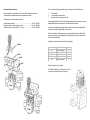
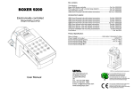
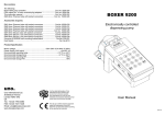
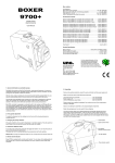
Box contains
One of the following pump controllers:
Unoverse 2-4 channel pump unit ................................................... Cat. No. 6600.001
Unoverse 4-8 channel pump unit ................................................... Cat. No. 6600.002
Unoverse 6-12 channel pump unit ................................................. Cat. No. 6600.003
One size of the following tube sets:
Unoverse Pharmed Tubing IDØ0.5mm dual assy............................. Cat.No.6000.506
Unoverse Pharmed Tubing IDØ1.0mm dual assy............................. Cat.No.6000.501
Unoverse Pharmed Tubing IDØ1.5mm dual assy............................. Cat.No.6000.502
Unoverse Pharmed Tubing IDØ2.0mm dual assy............................. Cat.No.6000.503
Unoverse Pharmed Tubing IDØ2.5mm dual assy............................. Cat.No.6000.505
Unoverse Norprene Tubing IDØ3.0mm dual assy ............................ Cat.No.6000.504
For Unoverse 1001 - 2 sets of tubes
For Unoverse 1002 - 4 sets of tubes
For Unoverse 1003 - 6 sets of tubes
Foot Switch ............................................................................................. Cat. No 6013
Power Supply Unit .................................................................................. Cat. No.6028
Instruction manual ......................................................................... Cat. No.6000.6106
Product Specification:
Mains Voltage ............................................................ 100V-240V 1.0A MAX 50-60Hz
Power Supply Unit output ...................................................................... +15VDC 2.0A
Environmental operating temp ............................................................ +10°C to +40°C
Environmental storage temp ................................................................. +4°C to +40°C
Fuse ....................................................................................................................3.15A
uno.
electronically controlled
dispensing pump
User Manual
Uno International Ltd.
20 Belsize Avenue
London NW3 4AU
UK
Tel.: +44 (0) 20 7794 4080
FAX:+44 (0) 20 7431 1426
Email: [email protected]
www.boxerpumps.com
It is the stated philosophy of Uno
International Ltd to preserve the
environment wherever possible.
Uno International Ltd. will only use
materials and production techniques that
cause least environmental damage.
The CE sign certifies that the instrument
meets the requirement of the EEC
directives and has been tested according
to the specified test methods.
Unoverse Pump Accessories
The volume delivered by any peristaltic pump is a function of the following factors:
Some accessories are available for the Unoverse Pump Dispenser as standard.
Custom design for dispense heads can be manufactured to order.
1.
2.
3.
The following is a list of standard components
8 channel dispense head ................................................................ Cat. No. 6600.007
Support bracket for 8 channel dispense head................................. Cat. No. 6600.008
8 channel multilumen tubing ID Ø1.0 - 1m long .............................. Cat. No. 6600.009
Tube diameter
Circular distance between rollers
Speed in which the rollers pass the tube
A pump equipped with four rollers will deliver approximately double the volume of a pump
equipped with eight rollers arranged over an identical circular diameter.
However, a pump equipped with eight rollers will deliver the volume with roughly double
the precision of a pump equipped with only four rollers.
Due to the fact that the dispense precision is among others determined by the ID of the
tubes used in the pump, a great emphasis should be given to the correct choice of tube
for the intended application.
Generally we recommend to adhere to the following table:
6600.009
6600.007
6600.008
6600
Tube diameter
0.51
1.03
1.52
2.06
2.54
dispense volume ul
4μl/min to 200μl/min
20μl/min to 400μl/min
100μl/min to 10ml/min
500μl/min to 25ml/min
2ml/min to 50ml/min
CV%
0.75
1
2.5
4
5
Dispense volumes are per channel.
To facilitate the fitting of your delivery tubes turn the
unit on its back so that the pump unit faces up.
1. Preparing Unoverse 1000 for use
1.C. Inserting the tubes
1. A. Unpacking
Unclip the tube clips from the
pump head by pressing the two
tabs together and hinging the clip
from the pump head.
Place the shipping box on the floor, open the box’s tabs, carefully remove the packing
chips and unpack the sub component.
Following the unpacking of the unit, make sure that you have all the following
components. Please contact your supplier immediately if you notice one of the
components to be missing or damaged.
Note: Do not attempt to assemble a unit using damaged components.
Unoverse pump dispenser ..................................................... Cat. No.6600.00X
Unoverse Tubing .................................................................. Cat. No.6000.XXX
Power supply unit ......................................................................... Cat. No.6028
Foot Switch ................................................................................... Cat. No.6013
This user manual ................................................................. Cat. No.6000.6106
Retain the packaging in case you have to ship it in the future.
Unpack the tubing and slide the
tube holders into the provided
slots in the pump head.
Refit the tube clips into their
position.
The remote power supply unit is a Switch Mode Power Supply and automatically
adjusts itself to the mains power supply characteristics and will work with any mains
voltage from 100V to 240V.
1. B. Positioning the Unoverse
8 roller system Volume
dispensed per channel in ml
4 roller system Volume
dispensed per channel in ml
6000.506
0.51
0.445
0.500
6000.501
6000.502
6000.503
6000.505
1.03
1.52
2.06
2.54
1.250
2.050
3.200
4.450
1.515
2.900
5.250
7.750
Calibration data:
Volume represents 25 roller
rotations.
See page 7 for detailed
calibration procedure
Tubeset part no
Place the Unoverse unit on a solid surface adjusting the levelling feet by screwing them
in or out until the unit is horizontally level and stable.
Tube inner diameter
Unoverse 6600 requires an operation environment of between 10 ºC – 40 ºC
2. Familiarizing
2. B. The Unoverse pump controller
2. A. General information on peristaltic pumps
Unoverse pump tubing is delivered clipped onto the tube supports using a tube fitting.
You should connect your delivery tubes to each of the channels entry and exit taking
into account that the entry of each channel will be opposite to the exit and one row
exits is situated adjacent to one row of entries to the parallel channel.
Peristaltic hose pumps are ideal for fluid transfer, metering and dispensing. In contrary to
centrifugal and gear pumps, peristaltic pumps handle fluids of various viscosities, are self
priming and operate in two flow directions.
With no valves, seals or packing to come in direct contact with the pumped fluid, they are
ideal for pumping high purity & corrosive fluids and for contamination free dosing.
The principle of the peristaltic pump is based on a tube which is squeezed by a series of
rollers.
All other peristaltic pumps on the market have the rollers arranged radially in a circle with
the tube wrapping around the circle in a U shape. The rollers engage with the tubes over
a section of 270º. The outlet and the inlet to the tube are adjacent to each other.
The tube fitting is chosen to cater for tube size which will eliminating over pressurizing
the peristaltic tubes. An unbalanced pressure in the tubes will effect the dispense
precision of the pump.
The delivery tubes should therefore ideally be of similar diameter to the peristaltic
tubes in the pump. A smaller diameter tube should form the dispense nozzle if ‘droptear-off’ is required.
Plug the Power Supply unit into your mains socket. A green light on the power supply
unit should indicate that the unit works properly.
Insert the foot switch plug into the provided socket if foot switch operation is desired.
Connect the low voltage power plug into the power socket on the Unoverse unit and
switch on the equipment by gently pushing the on/off switch.
The Unoverse pump head adopts a unique
principle whereby the tubes are engaged with
the rollers over a section of 95º only. This
arrangement allows the fitting of two tubes to
both sides of the roller wheel with the
advantage of 50% space saving, a balanced
and much reduced motor load and less wear
on the tubes.
OUT
IN
The green LED indicates that the pump is fully operational.
The display will read ‘6600’ and default to the value 1.000 . This value is a factory
setting and represents 25 rotor rotations.
On/Off
Push Switch
3.15A Fuse
Power socket
Foot switch
Pump direction slide switch
IN
OUT
3. The Control Panel
4.A. Quick Calibration for 8 roller head system
The keys on the control panel are assigned with functions to calibrate the pump, set the
volume to be dispensed, to set speed and ‘interval dispense’.
For a quick pre calibration procedure we collected the nominal dispense volume data for
each of the popular tube diameters. This data will help you towards a rough pump
calibration.
Some of the keys must be operated in pairs to enter certain functions of the dispenser. In
such cases, the keys should be activated in the following sequence :
CAL+UP .................................... Increase the calibrated volume
CAL+DOWN ............................ Decrease the calibrated volume
VOLUME+UP .................................................. Increase volume
VOLUME+DOWN ........................................... Decrease volume
CAL+RANGE ....................................... Moves the decimal point
CAL+START.................................................... Set default 1.000
INTERVALS................................. Enter interval dispense mode
INTERVALS + UP/DOWN .......................... Set interval duration
INTERVALS + UP/DOWN .................. Set number of dispenses
SPEED+UP ................... Increase dispense speed to max (255)
SPEED+DOWN ................................ Decrease dispense speed
START ................................................. Start dispense operation
VOLUME+START..................................... Continuous dispense
STOP ...........................................Stop dispense (‘panic button’)
STOP (>2 seconds) ........ Stop & cancel interval dispense mode
4. Pump calibration procedure
Due to the fact that pump heads can be fitted with various tubes, each pump requires
calibration before the pump can be commissioned.
Although the tubes are precision extruded and the tubes which we supply in pairs
generate from a single batch, there are small tube to tube tolerances which will effect the
overall dispense accuracy of the pump.
Tube to tube calibration can only be achieved by measuring the volume dispensed from
each of the channels, and adjusting each tube separately to the tube which delivered the
lowest volume.
Follow the following steps:
1. Press CAL+START: Unoverse will display 1.000 . This
is a default calibration value.
2. Press CAL+UP or CAL+DOWN until the unit displays
the figure in table Page 2
3. Press CAL+RANGE to set the decimal point in the
correct position
4.B. Gravimetric or volumetric calibration
You can set Unoverse to display the dispensed volume per channel, per group of
channels, or as a total for the whole pump head.
As the peristaltic tubes change their diameter with use, a periodic calibration of the unit is
required.
By calculating the mean volume for each of the channels you will detect whether any one
of the channels is widely different in delivery from all other channels and therefore
requires replacement.
For general use, the dispensed volume used for calibration purpose should be taken from
the table in page 4. Alternatively, you can calibrate the pump using the volume you are
most likely to use in your application.
1.
2.
3.
4.
Press ‘VOLUME+UP’ or ‘VOLUME+DOWN’ until the desired volume for calibration
is displayed.
Carry out five dispenses and establish the volume dispensed from the total
number of channels
Calculate the mean delivery volume for each channel (ΣV/n channels)
Enter the value into the Unoverse unit by pressing ‘CAL+UP’ to increase the
displayed volume or ‘CAL+DOWN’ to decrease the dispensed volume
Press ‘CAL+RANGE’ to move the decimal place so that the unit displays the
volume in ml.
Adjustment to tube is achieved by stretching the tube.
5.
In the majority of cases, a calibration for the pump head as a whole will be sufficient. The
following section refers to calibration of the pump head as a whole whilst running all
channels in parallel.
Unoverse is now ready for dispense.
We recommend carrying out gravimetric or volumetric calibration. The most common
practice is to set the unit to display the dispensed volume per channel. You can however
also set the display to read the total dispensed volume.
5. Adjusting the dispense volume
8. Changing the pumps direction
Press keys ‘VOLUME+UP’ or ‘VOLUME+DOWN’ to enter the volume nearest to your desired
volume.
Unoverse pumps can be used for dispensing or aspirating. The slide switch on the side of
the unit sets the direction in which the motor rotates.
Make sure the tubes terminate in a receiving vessel and press ‘START’ to begin dispensing.
For priming or to dispense more than the set volume , hold down the START key.
When the slide is in the forward position the roller wheel will rotate clockwise as seen
from the operators angle and anti clockwise when the slide switch is in its backward
position.
6. Interval Dispense
You can set the unit to dispense the desired volume for a number of times in predefined
intervals. This feature is useful in repeatable operations either in manual mode or when the
dispense head is held by a robotic arm.
To set repeat dispensing in selectable intervals:
1. Interval range selection: Press and hold down the ’INTERVAL’ key. You will
see 01 for range of 1-99 seconds intervals or 10 for a range of 10-990 seconds
intervals. Press ’DOWN’ to select1 to 99 seconds or ‘UP’ key to for 10 to 990
seconds. Release the ‘INTERVAL’ key. The display flashes the first two digits to
the left. These digits denote the time in seconds between the dispense
operations—either 1-99 or 10 to 990 seconds.
2. Hold the ‘INTERVALS’ key down and using the ‘UP’ & ‘DOWN’ keys enter
the number of seconds or 10Xsec you wish to have between the dispenses—
from 1 second to 990 seconds. Release the ‘INTERVALS’ key to save your
settings.
The second set of digits will flash. This digits denote the number of dispenses
you wish to have—from 1 to 98 dispenses.
3. Press ’INTERVALS’ + ‘UP’ & ‘DOWN’ keys enter the number of dispense
events—between 1 and 98.Release the ‘INTERVALS’ key to save your settings.
The display will show the volume. The colon between the two sets of digits
flashes to indicate that an interval dispense mode has been entered into the
unit. You can now adjust the volume as indicated in the previous paragraph.
01
6. To exit interval mode: press + hold ‘STOP’ button for more than 2 seconds to
terminate the intervals mode . The flashing colon will disappear from the display.
To change any of the interval parameters simply press the ‘INTERVALS’ key
again and enter new parameters
00:0
10. Continuous dispense mode
The pump displays ‘Cont’ to indicate continuous running.
Please note that running the dispense tubes dry over a long period may shorten their life.
11. Overload Protection Mode
03:0
Whenever the motor is overloaded beyond it’s safe operation capability, an overload
protection circuitry will switch the motor off. The display will read O-L (meaning OverLoad). To restart normal dispense operation, press the STOP button.
12. Care & maintenance
03:0
The control unit is maintenance free. The peristaltic tubes however require replacement
as soon as excessive wear or a large variation in dispense volume is noticed.
8 events
3 seconds
intervals
The operational life of the tubes is a function of the speed and load on the tubes.
0.5:
Avoid running the tubes dry for longer than a few minutes.
Check the peristaltic tubes on a weekly basis and renew if required.
Pump tubes which remain clamped in the pump deform with time. Therefore, unclip the
tube clip at one side of the clip to relieve the pressure from the tube whenever the pump
is idle for longer periods and overnight.
13. Exclusion
Note that in the dispense process the display shows the seconds left before next
dispense and the running event number.
7. Continuous interval dispense: To dispense your chosen volume
continuously at the interval time you selected, enter ‘99’ as the number of
repeats. This will prompt the unit to dispense continuously until the STOP button
is pressed. Remember to check the tubing condition from time to time.
The speed control adjusts the voltage supply to the motor.
To adjust the speed of dispense press ‘SPEED+UP’ or ‘SPEED+DOWN’ to increase or
decrease the speed.
Please note that a speed set too low may stall the motor.
To run the pump continuously press ‘VOLUME+START’. You can stop the pump at any
point by pressing the ‘STOP’ button.
4. Press ‘START’ and the controller will dispense the set volume in the interval
mode which you have entered into the unit.
5. Panic stop: You can press the ‘STOP’ button at any point throughout the
dispense mode to terminate the automated dispense operation.
9. Pump speed adjustment
0.5:
If the equipment is used in a manner not specified by the manufacturer, the protection
provided by the equipment might be impaired.
Not suitable for use in explosion hazard environments.