1
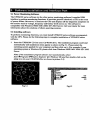
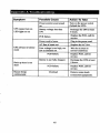
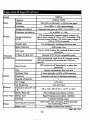
Best uninterruptible power system
for your audio video entertainment devices
1000VA
USER'S MANUAL!
Important Safety Instructions
IMPORTANT SAFETY INSTRUCTIONS
SAVE THESE INSTRUCTIONS
• WARNING (SAVE THESE INSTRUCTIONS): This manual
contains important instructions that should be followed during installation and
maintenance of the UPS and batteries.
• WARNING (CONTROLLED ENVIRONMENT): These units are
intended for installation in a temperature controlled, indoor area free of conductive
environment.
• CAUTION: Risk of electric shock, do not remove cover. No user serviceable parts
inside. Refer servicing to qualified service personnel.
• CAUTION: Do not dispose of batteries in a fire, the battery may explode.
• CAUTION: Do not open or mutilate the battery, released electrolyte is harmful to
the skin and eyes. It may be toxic.
• CAUTION: A battery can present a risk of electric shock and high short circuit
current. The following precaution should be observed when working on batteries
Remove watches, rings or other metal objects.
Use tools with insulated handles.
Wear rubber gloves and boots.
Do not lay tools or metal parts on top of batteries.
Disconnect charging source prior to connecting or disconnecting battery terminals.
• Servicing of batteries should be performed or supervised by personnel knowledgeable
of batteries and the required precautions. Keep unauthorized personnel away from
batteries.
• When replacing battery, replace with same type.
• Do not connect any additional batteries by yourself.
•
Symbol for On/Off is displayed and defined.
• CAUTION: To reduce the risk of fire, connect only to a circuit provided with 20
amperes maximum branch circuit overcurrent protection in accordance with the
National Electrical Code, ANSI/NFPA 70.
Table of contents
Important Safety Instructions
I
Table of contents
II
Introduction
1.
2.
IV
Presentation
5
Front Panel
5
Rear Panel
6
LCD message panel display
8
Installation
9
2.1 Inspection:
9
2.2 Recharge the battery:
9
2.3 Connect the loads:
9
2.4 Utility Power:
9
2.5 Connect to the utility power:
9
2.6 Overload protection:
9
2.7 Optimal battery status:
9
2.8 Self-protection feature:
9
2.9 Auto restart feature:
9
2.10 Storage:
9
2.11 Power failure:
3.
4.
5.
9
Operation
10
3.1 Simple test:
10
3.2 Check the power requirement of your equipment
10
3.3 Limited rating power of UPS:
10
Alarm
10
4.1 "BACKUP" (slow alarm):
10
4.2 "LOW BATTERr (rapid alarm):
10
4.3 "OVERLOAD" (continuous alarm):
10
Software installation and Interface Port
11
5.1 Power Monitoring Software
11
5.2 Installing software
11
5.3 Connecting interface cable
12
II
5.4 The characteristics of software UPSMON
6. Maintenance and storage
12
14
6.1 Maintenance
14
6.2 Storage conditions
14
6.3 To extend the storage
14
Appendix A Troubleshooting
15
Appendix B Specifications
16
© Ground LED indicator
This indicator is illuminated when grounding is normal.
© EMI/RFI LED indicator
This indicator light is illuminated when noise filtration is working properly.
© Time setting button
This button is for setting time (hours).
Rear Panel
e
©
©
©
O Network Line Protection
Telecom transfer ports are used to protect user's communication device form spike.
Caution: To reduce the risk of fire, use only No. 26AWG or larger telecommunication line
cord.
© Phone Line Protection
Phone jacks are used to protect user's phone form spike.
© USB Port
Through this remote Port, user can monitor UPS. (Please see chapter 5 for details)
© Bypass Outlet Stage 1
6
0 Bypass Outlet Stage 2
0 UPS Outlet Stage 3
When utility power is normal, the UPS outlets are powered by utility power with AVR
function. Any higher or lower utility power would be rectified by AVR function. When
utility power is fail, the UPS outlets are powered from battery.
© Circuit Breaker
It trips when the connected loads exceed the protected receptacle's capacity.
© Input Power Cord
The input power cord needs to be plugged into a socket on the wall. Please notice the voltage
of utility power should match with the UPS. For example, the rating voltage of UPS is 110V
(220V), the input utility power should be the same as 110V (220V).
O Coaxial Line Protection
This coaxial surge suppression ports are used to protect device connected through coaxial
cable from surge.
LCD message panel display
O Digital clock:
Digital clock displays present time (adjustable).
© AVR (Automatic Voltage Regulation) activate:
The text "AVR Activate" illumination indicates that the AVR feature is functioning.
© Battery charge level:
This display indicates battery charging level in AC mode.
© Battery run time:
This display indicates battery status in back-up mode.
© Input voltage:
This display indicates the input voltage.
© Battery load level:
This display indicates the output load of the UPS unit.
2.
Installation
2.1 Inspection: Inspect the UPS upon receipt. Packaging can be recycled or reused for
transportation of the UPS unit.
2.2 Recharge the battery: The UPS may be used immediately upon receipt. The battery is
fully charged before shipping from the factory. Energy loss may occur during shipping or
storage, so it is recommended that the battery recharge at least four hours before first using
the UPS. To recharge the battery, plug the UPS be into an AC outlet and switch on.
23 Connect the loads: Plug in primary equipment (e.g. computer, monitor and critical data
storage device, etc.) into the Battery Power-Supplied outlets. Plug in peripherals (e.g. printer,
scanner, fax, or audio device) into the Surge Protection outlets. Do not plug a laser printer to
the UPS since its power demand is much higher than typical peripherals and it may cause the
circuit breaker to trip.
2.4 Utility Power: The input power cord on the rear panel needs to be plugged into a wall
socket. Please note that the electrical power voltage should match with the UPS. (For
example, if the UPS voltage is 120V, the incoming electrical power should be 120V as well.)
2.5 Connect to the utility power: Plug the UPS into a 2-pole, 3-wire grounding receptacle.
Make certain that the branch is protected and does have not service equipment requiring
heavy electricity (e.g. refrigerator, air conditioner, copier, etc.). Avoid using extension cords.
2.6 Overload protection: If an overload situation is detected during the self-test, an audible
alarm will activate, emitting a long beep and automatically shutting down the system.
Unplug at least one piece of equipment from the Battery Supplied Outlets. Switch off the
UPS and wait for 5 seconds. Next, make certain that the circuit breaker is set and then switch
UPS on again.
2.7 Optimal battery status: To maintain optimal battery charge, leave the UPS plugged in
and switched on at all times.
2.8 Self-protection feature: The UPS is equipped with a self-protection feature that
prevents accidental damage if the unit is turned on and off repeatedly. Once the unit is
switched off, the user must wait 5 seconds before switching UPS on again.
2.9 Auto restart feature: The UPS is equipped with an Auto Restart feature which activates
when the battery level becomes too low to sustain operation and electricity is not present
The UPS will switch itself to Suspend Mode in order for electric power to return and
recharge the battery. If the user is away during a utility failure, the UPS will reset itself to
normal function and recharge its battery when electrical power returns.
2.10 Storage: To store the UPS, first turn off the unit. Then, cover it and store it with the
battery fully charged. During extended storage, recharge the battery every three months to
ensure battery life.
2.11 Power failure: In the event of a power failure occurring after turning on UPS and
before the initial self-test sequence, the UPS will automatically shut down and not restart
until electrical power is restored. This allows the unit to check the quality of power that is
delivered to the connected equipment.
3.
Operation
3.1 Simple test: It is recommended that the user perform a simulation test when using
UPS for the first time or when connecting an additional piece of equipment. To conduct
a simulation test: First, switch on the UPS and wait for the power indicator to light up.
Then simply unplug the power cord to simulate a power failure.
CailtlOn: Never connect a laser printer or a plotter to the UPS with other computer
equipment A laser printer or plotter periodically draws significant power and may overload
the UPS.
3.2 Check the power requirement of your equipment
3.2.1. Make sure the total power of your equipment does not exceed rating capacity.
3.2.2. Also, check that the equipment plugged into the Battery Power-Supplied outlets does
not require total power exceeding the capacity of the UPS. Otherwise, overload may occur
and cause the circuit breaker to trip. If the power requirement of your equipment differs
from VA, convert the requirement power into VA by doing the calculations below in 3.2.3.
3.3.3. If the power requirement of your equipment is listed other than VA, convert the
requirement into VA by doing the calculations below:
For 120V Systems:
Watt (W) X 2 = _VA, or Amps(A)X 120V=_VAFor
220V Systems:
Watt (W) X 2 =_VA, or
Amps(A) X 220V=_VA
3.3 Limited rating power of UPS: When electrical power failure occurs, the battery power
outlets will supply power to connected equipment from its battery and the alarm will beep
once every 2 seconds. Be sure that equipment is running under the limited rating power.
Restore power by plugging UPS back into the existing power source. Repeat the test a few
times to make sure UPS works properly and to determine the expected runtime.
4.
Alarm
4.1 "BACKUP" (slow alarm): When the UPS is working under "BACKUP" mode, the UPS
emits an audible alarm. The alarm stops when the UPS returns to "LINE" mode operation.
Note: The alarm of "BACKUP" beeps every 2 seconds. (Slow-speed beep).
Note: The UPS provides an auto-mute function for the warning. When the backup
beeping sound occurs, it will mute automatically after 1 minute.
4.2 "LOW BATTERY" (rapid alarm): In the "BACKUP" mode, when the energy level
of battery is low (about 20%-30%) die UPS beeps rapidly until it shuts down from battery
exhaustion or returns to "LINE" mode operation.
Note: The alarm of the batteries caused by low voltage beeps every 0.5 second.
4.3 "OVERLOAD** (continuous alarm): When the UPS is working under overload
conditions (i.e., the connected loads exceed the maximum rated capacity), the UPS will
emit a continuous alarm to warn of the overload condition. In order to protect the unit and
the loads, the UPS will automatically turn off. Disconnect nonessential devices from the
UPS to eliminate the overload alarm.
10
5. Software installation and Interface Port
5.1 Power Monitoring Software
The UPSMON series software (or the other power monitoring software) is applied USB
interface to perform monitoring functions. It provides graceful shutdown of OS in the event
of power failure. Moreover, it monitors the UPS and displays all the diagnostic symptoms on
the monitor such as voltage, frequency and battery level and so on. The software is
compatible with Windows 98SE/ ME/ 2000/ XP/ 2003 Server. Call your dealer for more
information about the solutions of others operating systems.
5.2 Installing software
To perform monitoring functions, you must install UPSMON series software accompanied
with the UPS. Please do the following steps to complete installation of UPSMON series
software.
1.
Insert the UPSMON CD into your CD-ROM drive. The installation program could start
automatically and installation menu appear as shown in Fig 5.1. Please select the
operating system applied for your computer and then click on it. (For example if your
operating system is Windows 98, please click item Windows 98SE/ ME/ 2000/ XP/ 2003
Server.
Note: If the installation program doesn'/ start automatically, select
Start ^Programs-^Windows Explorer (for Windows 98) and then double-click on the
setup icon (in your CD-ROM drive as shown in picture 5.2).
rinux
G3 Netware
GlWtndovt
1KB
1,009KB
1KB
Fig 5.1
Fig5.2
11
6.
Maintenance and storage
6.1 Maintenance
6.1.1. Keep the unit clean and vacuum the ventilation intake periodically.
6.1.2.
Wipe with soft loose and damp cloth.
6.1.3.
Check for loose and bad connections monthly.
6.1.4.
Never leave the unit on an uneven surface.
6.1.5. Position the unit to allow at least 10 cm clearance between the rear panel and the
wall. Keep the ventilation intake open.
6.1.6.
Avoid direct sunlight, rain and high humidity.
6.1.7.
Stay away from fire and extremely hot location.
6.1.8.
Do not stack materials on top of the unit.
6.1.9.
The unit should not be exposed to corrosive air.
6.1.10 The normal operating temperature is 0-40°C.
6.2 Storage conditions
Store the UPS covered and upright in a cool and dry location, with its battery folly charged.
Before storing, charger the UPS for at least 6 hours. Remove any accessories in the
accessory slot and disconnect any cables connected to the computer interface port to avoid
unnecessary draining the battery.
63 To extend the storage
6.3.1. During the environment where the ambient temperature is -15 to +30 °C(+5 to +86
°F), charge the UPS's battery every 6 months.
6.3.2. During the environment where the ambient temperature is +30 to +45 °C(+86 to +113
°F), charge the UPS's battery every 3 months.
14
Appendix A Troubleshooting
15
Appendix B Specifications
2007,04, V01
16