1
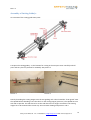
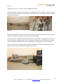
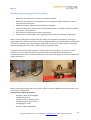
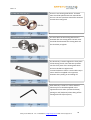
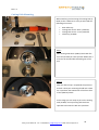
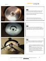
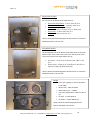
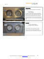
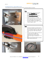
Rev 1.3
1
Safety Tools Allmet AS. Tlf. + 4756323650 [email protected] Web: www.safetytools.no
Rev 1.3
UsermanualCuttingGuideJr
Documentation created by STA Solutions AS for SafetyTools Allmet AS.
Content
1.
Function/document description...................................................................................................... 2
Version control .................................................................................................................................... 3
2.
Important safety information.......................................................................................................... 3
3.
Special Connditions ......................................................................................................................... 7
4.
Equipment Overview ....................................................................................................................... 9
5.
Operation manual / Procedure ..................................................................................................... 10
Preparation........................................................................................................................................ 10
Assembly of Cutting Guide Jr............................................................................................................. 11
Setting up the Cutting guide Jr for cutting ........................................................................................ 13
Setting up the Cutting guide with possibility for drop ...................................................................... 14
Operating the cutting guide Jr. .......................................................................................................... 14
After using the Cutting Guide ............................................................................................................ 16
6.
Maintenance plan.......................................................................................................................... 16
7.
Water control box ......................................................................................................................... 17
Cutting Disk Mounting....................................................................................................................... 20
Setting the Water control Box for use............................................................................................... 24
8.
Warnings........................................................................................................................................ 25
Keep this manual in a safe, accessible place at all times
Keep this instruction manual for future reference. Additional safety information may be available from
the authorized agent in your country. Consult them when necessary. Do not remove or allow any
labels to become obscure.
1. Function/document description
This document is an instruction for operating of SafetyTools Cutting Guide Jr – A-0320.
2
Safety Tools Allmet AS. Tlf. + 4756323650 [email protected] Web: www.safetytools.no
Rev 1.3
Version control
Rev
1.0
1.1
1.2
1.3
Changes
Document created
Separate air supply wcb and operator suitcase
Pressure and force down table removed. Separate table attached.
Some smaller changes for ATEX certification.
Date
12.04.13
18.07.13
30.10.13
10.12.13
User
AH
AH
AH
AH
2. Important safety information
Read these instructions fully before use. Failure to do this may result in serious injury. The user
of this equipment must be competent in its use. The user must ensure that the equipment is selected,
installed and used in accordance with regulations and is checked fully before use. The equipment
must only be used for its intended purpose and be maintained regularly.
Safety is a primary consideration when using Safety Tools equipment. The tools should be used in the
correct way with a good understanding of how to use the tools safely. The tools together with
attachments and accessories should only be used for the purpose for which they are designed. Safety
devices and accessories supplied should be used appropriately. Do not use outside the design intent
unless first agreeing upon such use with the manufacturer and/or authorized agent. Read and fully
understand all the instructions before attempting to install, use, service or maintain the equipment.
Training is available through Safety Tools Allmet and the authorized agent in your region. Training
from Safety Tools Allmet and/or the Authorized agent in your region is required prior to using Safety
Tools Cutting & Weld Seem Removal tools. Training is also required for Cutting guide Jr.
WARNING
To reduce the risk of injury, before using or servicing tool, read and understand the following
information. The features and descriptions of our products are subject to change without prior notice.
This product is designed for cutting & removing material using abrasives. The abrasives are very hard
and solid (9.7+ Rockwell scale). No other use permitted - for professional use only.
Before servicing of the pneumatic tool, the supply of compressed air must be disconnected or shut off.
Training is required before using Safety Tools Cutting Equipment. Safety Tools Allmet offers training at
our office in Norway and offsite. Training is also available through the Authorized Agent in your region.
*See water control box information on page 17 of this Manual.
Disposal
When disposing of components, lubricants, etc … ensure that the relevant safety procedures are
carried out
3
Safety Tools Allmet AS. Tlf. + 4756323650 [email protected] Web: www.safetytools.no
Rev 1.3
Air Pressure
Check hose size and air pressure. The air pressure at the tool inlet with the grinder running shall not
exceed the maximum operating pressure of 7 bars or lower if other specified. The tool is designed for
a working pressure of 6.3 bar (90 psig). The compressed air must be clean and dry. The installation of
a filter is recommended. For maximum efficiency and performance, comply with the specification of the
air hose (antistatic, earthed hose). Avoid the risk of whipping hose – regularly check hose, hose fitting
and clamp conditions.
Always use the correct and clean air hose and fittings and check that they are all in good condition
and are properly installed. Do not use damaged, frayed or deteriorated hose end fittings. Replace
them when necessary. Always store hoses properly. A hose failure can cause injury. The air hose may
come off and whip. Use only earthed hosing in ATEX zones. See DNV report. Air should be supplied
at a constant pressure of 6.3 Bar at the tool with the trigger fully depressed. In-Line lubricators and air
filters are not required unless it is known that plant air supply is likely to be contaminated. It is
recommended that oil is added to the tool after prolonged use. See maintenance information.
Water Pressure
Check hose size and water pressure. The water pressure shall not exceed the maximum operating
pressure of 2.5 bar. The tool is designed for a optimum working pressure of 2.3 bar. The water must
be clean. The installation of a filter is recommended. For maximum efficiency and performance,
comply with the specification of the hose (antistatic, earthed hose). Avoid the risk of whipping hose –
regularly check hose, hose fitting and clamp conditions.
Always use a clean water hose and fittings and check that they are all in good condition and are
properly installed. Do not use damaged, frayed or deteriorated hose end fittings. Replace them when
necessary. Always store hoses properly. A hose failure can cause injury. The hose may come off and
whip. Use only earthed hosing in ATEX zones. See DNV report. Water should be supplied at a
pressure greater than 4 Bar for maximum efficiency.
Cutting Tempratures
Safety Tools Allmet Explosive test were performed using a robotic system. It is not possible using nonmachanical systems to reach high heat levels when the tools are used under human conditions. The
average temprature range when using Safety Tools Cutting equiptment is 25°C - 45°C. It is not
possible to exceed 100°C (T4) when using Safety Tools Cutting equipment under normal human
conditions. See DNV ATEX Certificate.
Safety Tools Ex Grinding Equipment is suitable for use in ambient temperatures Greater than -20°C to
40°C (see Special conditions for safe use on Page 7).
•
•
Air supply must be dry & clean.
Water Supply should be clean (filter recommended) and above 4 bar.
4
Safety Tools Allmet AS. Tlf. + 4756323650 [email protected] Web: www.safetytools.no
Rev 1.3
Types of Steel Tested
Safety Tools Allmet performed test on the 6 different materials, three different steel qualities and two
different titanium qualities below.
•
•
•
•
•
Stainless Steel Grade 316
Steel ST52
Titanium
ASTM B265 Titanium
Austenitic Stainless Steel 6MO
Maintenance
To obtain maximum efficiency from the pneumatic tool, preserve its features and avoid repeated
repairs, a routine inspection and repair program are recommended at least every 1000 hours, the
intervals between the various inspections depending on the amount of exertion on the power tool.
Safety Tools ATEX certified Air Tools must be properly maintained and tested by competent and
trained personnel. At any sign of malfunction or unusual behaviour, the tool should be taken out of
service for examination and repair. If repairs are necessary contact the authorized agent in your
country. It is recommended to dismantle air tools for overhauling and cleaning after 500 hours of
operation or once every six months.
•
•
•
•
Before cleaning the tool for use make sure that it has been correctly assembled. With all
fasteners tightened.
Check the rotation frequency of the tool without an attached disk. After each maintenance or
service.
If you are uncertain about the correct way to service a tool contact the authorized agent in
your region.
Only trained people should service and maintain Safety Tools equipment.
*See water control box information on page 17 of this manual for maintenance of the water
control box.
*See Cutting Guide Jr maintenance plan on page 16 in this manual for maintenance plan on the
guide.
Check the free speed of the tool at regular intervals and after each operation or maintenance
task. Remove the disk to check the speed. The maximum allowed speed shown on the tool must not
be exceeded and the vibration level must not be excessive.
5
Safety Tools Allmet AS. Tlf. + 4756323650 [email protected] Web: www.safetytools.no
Rev 1.3
Motor speeds
These cold grinding tools are designed for use with the following motors:
Motor type
RPM
Max air pressure
Air hose diameter
(A-0105) Fuji FCD-10X-52 special
1000
6,3 Bar
9.5mm (3/8 inch)
Noise
The operator must wear ear protection when the noise level at his position exceeds 83dB or 85 dB. It
is recommended that the operator wears the ear protector even if the noise level is less than 83dB or
85 dB. Noise regulations might vary in different regions or companies. Check with local authorities
Noise levels while grinding with Safety Tools Cutting Guide Jr.
•
See attached noise report.
Vibration Analysis HAV
There is no vibration from the cutting guide to the operator when using SafetyTools Cutting Guide Jr.
Posture
Safety Tools are generally used as a hand-held unit. It is recommended that it is used whilst standing
on a firm surface. It may be used in other positions but it is important that the operator is in a secure
position and has a firm grip and footing. Refer to risk analysis for further guidance.
Safety Tools Allmet also has Robotic Systems and Automated Tool Guides. Contact Safety Tools
Allmet or the Authorized Agent in your Region for more information.
6
Safety Tools Allmet AS. Tlf. + 4756323650 [email protected] Web: www.safetytools.no
Rev 1.3
Protective Equipment
Always wear necessary protective equipment when using this equipment. Safety goggles or face
shield, gloves and hearing protection are required. Ensure all clothing is close fitting to prevent
becoming snagged in moving parts.
Safety Goggles / face shield
Mandatory
Hearing Protection
Mandatory
Safety Gloves
Mandatory
Safety Hat
Mandatory
Respiratory Protection
Optional
3. Special Connditions
Projectile Hazards for misuse
•
•
•
•
•
•
Always wear impact-resistant eye and face protection when involved with or near the
operation, repair or maintenance of the tool or changing accessories on the tool.
Be sure all others in the area are wearing impact-resistant eye and face protection.
Even small projectiles can injure eyes and cause blindness.
Use barriers to protect others from wheel fragments and grinding sparks.
Daily measure the air tool speed with a tachometer to make sure it is not greater than the
RPM marked on the grinding accessory.
This Tool and its accessories must not be modified in any way.
Entanglement Hazards for misuse
•
•
•
•
•
•
•
Keep away from rotating drive spindle and abrasive. Rotation may continue for several
seconds after the throttle has been released. Do not lay the tool down until rotation has
stopped.
Do not wear jewelry or loose clothing.
Choking can occur if neckwear is not kept away from tool and accessories.
Scalping can occur if hair is not kept away from tool and accessories.
When operating remotely controlled cutting equipment always use barring around the tool.
The tool has several moving parts. Always stay clear the tool when connected to air.
The tool might start unannounced.
7
Safety Tools Allmet AS. Tlf. + 4756323650 [email protected] Web: www.safetytools.no
Rev 1.3
Mounting Hazards for misuse
•
•
•
•
•
•
Always shut off air supply, relieve hose of air pressure and disconnect tool from air supply
when changing accessories.
Always shut off water supply, relieve hose of water pressure and disconnect tool from water
supply when changing accessories.
Use only recommended sizes and types of abrasives.
Do not use files or disks that are cracked.
Correct mounting is necessary to prevent injury.
Safety Tools Air Tools are specially designed to work only with Safety Tools Cutting Disks.
Only Use Safety Tools Air Tools and Accessories as they are designed. Do not use with other
Accessories and or Air Tools.
Operating Hazards for misuse
•
•
•
•
•
•
Operators and maintenance personnel must be physically able to handle the bulk, weight and
power of the tool.
Ensure that the work piece is properly supported.
Maintain a balanced body position and secure footing.
Avoid contact with rotating spindle and accessory to prevent cutting of hands and other body
parts. Wear protective equipment listed.
Do not use if vibration becomes excessive: check the accessory for damage or incorrect
mounting.
There is a risk of electrostatic discharge if used on plastic and other non-conductive materials.
Workplace Hazards for misuse
•
•
•
Slip/Trip/Fall is a major cause of serious injury or death. Be aware of excess hose left on the
walking or work surface.
High sound levels can cause permanent hearing loss. Use hearing protection as
recommended by your employer or occupational health and safety regulations.
Repetitive work motions, awkward positions and exposure to vibration can be harmful to
hands and arms. If numbness, tingling, pain or whitening of the skin occurs, stop using tool
and consult a physician.
Air Supply and Connection Hazards for misuse
•
•
•
Air under pressure can cause severe injury.
Always shut off air supply, drain hose of air pressure and disconnect tool from air supply when
not in use, before changing accessories or when making repairs.
Never direct air at yourself or anyone else.
Whipping hoses can cause serious injury. Always check for damaged or loose hoses and
fittings.
Whenever universal twist couplings are used, lock pins must be installed.
Do not exceed maximum air pressure of 6.3 bar/90 psig or as stated on tool nameplate.
Check and maintain air hoses regularly.
Use only Earthed/Anti-Static Hoses (2mm Maximum thickness on coatings) See DNV
information.
Make sure the air supply is clean and dry.
•
The ambient temperature for safe use must be greater than 0°C.
•
•
•
•
•
•
8
Safety Tools Allmet AS. Tlf. + 4756323650 [email protected] Web: www.safetytools.no
Rev 1.3
Water Supply and Connection Hazards for misuse
•
•
•
•
•
•
•
•
•
Water under pressure can cause severe injury.
Always shut off water supply, drain hose of air pressure and disconnect tool from water supply
when not in use, before changing accessories or when making repairs.
Never direct water at yourself or anyone else.
Whipping hoses can cause serious injury. Always check for damaged or loose hoses and
fittings.
Whenever universal twist couplings are used, lock pins must be installed.
Do not exceed maximum water pressure of 10 bar from water supply
Check and maintain water hoses regularly.
Make sure the water supply is clean and whiteout chemicals.
The ambient temperature for safe use must be greater than 0° Celsius. Water may freeze on
temperature close to 0° Celsius. Make sure water dos not freeze before use.
Special Conditions for safe use
•
•
•
•
•
•
The air tool must be earthed by a supply air hose. The air hose used must also be of antistatic type or satisfy the requirements of clause 7.4.4 of EN 13463-1.
Maximum air supply pressure is 6,3 Bar.
The cutting disk WC-502 shall only be used with an air tool with max 1000RPM and can only
be used against the following listed materials; stainless steel Grade 316, Steel ST52,
Titanium, ASTM B265 Titanium and Austenitic stainless steel 6MO.
The air tool must only be supplied from the water and pressurized air controller of type STA
water control box.
Water cannot be used as cooling medium at temperatures below 0°C.
For temperatures below 0°C an isopropanol/ethanol water mixture with 50% water can be
used as cooling medium.
4. Equipment Overview
Cutting Guide Jr:
-
1 off side w/ magnet and air engine
1 off Side w/magnet
2 off Guiding rods
1 off spindle
Cutting wagon/cylinder wagon.
Hose bundle
Operating suitcase:
-
Operator panel inside.
Cutting Solution:
-
Fuji Grinder
Water Control Box
Cutting disk.
9
Safety Tools Allmet AS. Tlf. + 4756323650 [email protected] Web: www.safetytools.no
Rev 1.3
5. Operation manual / Procedure
Preparation
•
Make sure that the work station and the surroundings are safe and clear of any oil, grease
etc.
•
•
•
•
•
•
•
•
•
•
•
•
Make sure that there is sufficient space for the cutting tool and the task to be carried out.
Provide for the best access for air hoses.
Provide for the best access for water hoses.
Verify that the working pressure is 6,3 bar for the rotating Air engines.
Verify that the water pressure supply to the control box is above 4 bar.
•
•
•
•
•
•
•
•
•
•
•
•
•
•
Use the correct lifting technique. Do not ever use the hose as a lifting handle.
Adopt a good stance and avoid overreaching
Make sure that air hoses are fitted with whip checks.
Make sure that water hoses are fitted with whip checks.
The operator must use the correct grinding tool for the task at hand.
Install the rotating file or disk. (Do not exert unnecessary force during this work)
Make sure that the equipment has the required marking in accordance with the ATEX. / DNV
certificate.
Do not modify the tool without first contacting Safety Tools Allmet
Do not use the tool until you are completely familiar with its operation.
The tool is to be earthed. Use an antistatic hose with a steel wire. Se DNV certificate for more
information
Do not use the equipment if it emits unusual sounds, or if it vibrates or the speed varies.
Do not touch a rotating file ore disk during operations, as this may lead to injury.
If you have long hair or wear loose garments, be careful so as to avoid your hair or garment
being caught in the equipment. Make sure hair and garments is not near the rotating parts.
Make sure that the grinding/cutting tool is fitted with safety START \STOP
Verify that the air hose has been installed in accordance with current regulations. This applies
to all connections.
Inspect the hoses visually to ensure that they do not leak air.
Test the machine by using the tool for approx. 30 seconds to make sure that everything has
been correctly installed.
Before using review Water Control Box information on Page 17- of this manual
Do not use the cutting tool if there are any damages to the tool, the guide or the operating
device.
Stop the tool and disconnect air and water if in doubt.
When unattended, always disconnect air and water.
10
Safety Tools Allmet AS. Tlf. + 4756323650 [email protected] Web: www.safetytools.no
Rev 1.3
Assembly of Cutting Guide Jr.
An overview of the cutting guide main parts:
Transport the cutting guide jr. to the location for cutting in the transport crate. Carefully take all
parts and carry them in position for assembly. See picture 1.
Picture 1
Picture 2
Start by threading the cutting wagon onto the two guiding rods. Then thread the “chain guard” onto
the spindle before threading it into the clutch on the cutting wagon (picture 2). The spindle has one
side with a sprocket. This side has to be on the side where the air engine is attached. The cutting
wagon has to be mounted the correct way. See overview drawing and picture 1 and 3.
11
Safety Tools Allmet AS. Tlf. + 4756323650 [email protected] Web: www.safetytools.no
Rev 1.3
Always set the clutch in “release” before threading the spindle.
Attach both of the side plates with magnets to the guiding rods and the spindle as shown in picture 1.
Fasten the guard and adjust the chain in such a way that the chain is not too loose and not touching
the guard. See picture 4
Picture 3
Picture 4
When the cutting guide is ready, mount the SafetyTool Fuji Angle grinder (A-0105) onto the cutting
wagon. Make sure it is attached correctly and is properly fastened.
Place the Operator suitcase and the water control box in range of the cutting guide and connect all
hoses according to markings. Make sure all connections are properly connected and that there are
no bends on any hoses. Make sure there is no possibility of entanglement by any moving parts.
Make sure that all the grounding cables are attached and that the system is grounded into a clean
and paint free surface so that the entire system is grounded.
Picture 5
12
Safety Tools Allmet AS. Tlf. + 4756323650 [email protected] Web: www.safetytools.no
Rev 1.3
Setting up the Cutting guide Jr for cutting
•
•
•
•
•
•
Make sure all maintenance procedures have been followed.
Make sure that the gears on the spindle and the air engine is aligned and that the chain is
tight and fastened properly.
Check for damages, debris and other defects on the guide.
Check that the guide is stable on the surface and that there is no danger of collision with any
tools, hoses or any obstacles.
Set up barrens and warning around the cutting area.
Follow country/area/company rules regarding work permits and notification regulations.
Make sure the cutting guide is aligned with the cutting area and adjust the height by turning the
height adjustment screws on both sides of the cutting guide. Make sure that the guide is parallel with
the surface it is going to cut. Also the height adjustment screws can be used to set the max cutting
depth by adjusting it as high as the cylinder can push the grinder down.
The guide can be fastened with magnets, vacuum (option) or by clamping it. It can also be used
sideways. Do not lift without proper fastening with safety. The magnets can be adjusted to
compensate uneven surface. Use the fastening screw on top of the magnet to loosen the magnet and
adjust. See picture 7.
Picture 6(always make use drop safety)
Picture 7
Before connecting air and water to the system, make sure that the Operator Suitcase has been set in
start position. See picture 8
Start position of Operator Suitcase:
- Emergency Stop Not engaged
- Cylinder Arm Lock
- Cylinder pressure High or Low
- Cutting/Cylinder wagon Stop
- Cutting Engine Off
- Vacuum Off (If applicable)
13
Safety Tools Allmet AS. Tlf. + 4756323650 [email protected] Web: www.safetytools.no
Rev 1.3
Picture 8
Picture 9
Connect water and air to the water control box and air to the Operator suitcase.
For moving of the guide when assembled use the wheels shown in picture 9.
For optimal performance; use separate air supply to the operator suitcase and the operator suitcase.
If separate hoses are not possible, try using a 1inch hose for supply then split it to the water control
box and the operator suitcase.
Setting up the Cutting guide with possibility for drop
Whenever the cutting guide is used where there is possibility of drops larger then 5cm the guide has
to be attached with proper fastening to prevent drops.
Operating the cutting guide Jr.
When all precautions and instructions in “Setting up the Cutting Guide Jr for cutting” have been
followed the guide is ready for cutting.
The Cutting guide Jr is operated by STA Solution Operating Suitcase. The different
instruments/levelers in the suitcase operate/indicates different functions on the cutting tool.
Functions of the Operator Suitcase:
- Emergency Stop shuts of air to the entire system (Except vacuum).
- Cylinder Arm This controls the cylinder that controls up and down of the Fuji Grinder. It
has a “lock” middle position for more manual control of the grinder. Can be used for the final
cut. (Contact SafetyTools for more information)
- Cylinder pressure you can set 2 different pressures on the regulators. The switch allows
the operator to quickly switch between two pressures.
- High / Low Pressure. The two regulators can be adjusted separately to different pressures
and therefor controlling the force the cylinder pressure the Fuji angle grinder down (depends
on material, thickness and where in the cutting process you are, contact SafetyTools if you
have any questions. Always regulate the pressure so that the cutting machine is running
without stops or reduced speed. The Grinder will break if forced.
14
Safety Tools Allmet AS. Tlf. + 4756323650 [email protected] Web: www.safetytools.no
Rev 1.3
-
-
Pressure and force down:
o The force down varies slightly from product to product. Please see own table for
min/max pressure force on your Cutting guide. Every cutting guide has a table for
pressure.
Cylinder wagon/cutting wagon this controls the air engine that drives the cutting wagon.
You can go forward, stop or backwards.
Cutting Engine this turns the Fuji angle grinder on or off.
Vacuum This is an option on the cutting guide. If applicable it turns on/off the vacuum
attachment device.
Air inlet this is for air inlet.
All air quick connectors are marked with similar marking on the hose bundle.
In operation:
Use the length of the Hose bundle to get the Operator Suitcase 3m away from the Cutting Guide Jr
for noise reduction.
Set the cutting wagon in start position and engage the clutch. The starting position is where you want
your cut to start.
Set wanted pressure on the regulators. Standard startup settings is High=0,24MPa and
Low=0,16MPa.
Start the grinder by turning “grinder” to on. (Read water control box setup page 17 for water control
box setup). When the grinder is working properly set the cylinder to “down”. When the cylinder is
going down and the grinding disc is engaging start the Cylinder/cutting wagon. The system should
now work. If the system does not work, press the Emergency stop and start fault finding.
When the desired length of cutting is reached switch the cylinder to “up” and use the clutch on the
cutting wagon to pull the wagon back to start position. Then switch the cylinder to “down” and
engage the clutch again. Repeat this until the desired depth is reached or until the plate is cut
trough.
For setting the machine to cut a predetermined depth, use the height adjustment on both side plates
to adjust it up and down. Adjust the guide so that the cutting disk is just above the surface when the
cylinder is all the way down. Then screw down both adjustment screws the wanted cutting depth.
On some materials the final mm can make the cutting disk “jam” itself and you will hear that the Fuji
grinder stats struggling or even stop. This is not good for the machine and it will break. Use the
“high/low” switch and switch it to low when you hear/see the machine start going slower. The “lock”
position on the cylinder can also be used for the final break trough.
Always adjust the pressure so that the cutting machine runs smoothly. (It will break if misused)
Do not leave the machine unattended while in operation.
15
Safety Tools Allmet AS. Tlf. + 4756323650 [email protected] Web: www.safetytools.no
Rev 1.3
After using the Cutting Guide
After using the cutting guide, be sure to unplug the air and water inlet.
Use water/air to clean the machine and make sure you don’t have cut debris on the machine. Don’t
use any chemicals on the guide.
Follow maintenance plan.
6. Maintenance plan
Part
Action
Fuji Air
motors
Fuji Air
motor
Pneumatic
switches
Chain/Gears
Guidance
Axel
Operator
suitcase
Water
control box
and grinder
Magnets
Vacuum foot
Antistatic
Guard
Cylinder
Brass
bearings
Daily Weekly
Add a drop of oil in the grinder
X
Clean with water. Make sure there is no
debris on the motor.
Each time the machine is to be used the
condition of the switches has to be checked.
Check for damages and debris. Check that
the gears or chain are not bent. Clean and oil
if necessary.
Check for damages and debris before use.
Clean and lubricate when necessary or after
12hours use.
Check for damages and debris before use.
Check daily and lubricate if necessary. Clean
and lubricate after 8 hours use.
Check that the suitcase isn’t damaged.
X
See own maintenance manual for grinder
and Water Control Box.
X
X
Make sure that the magnets are not
damaged. Clean for debris.
If applicable, make sure there is no damage
to the “vacuum” surface. Keep it clean
The Guard between the Water control box,
the guide and the Operator suitcase is
antistatic. Make sure this is not damaged.
Change if damaged.
Make sure there are no damages to the
Cylinder. Clean for debris.
Check brass bearings and change if damaged
or worn out.
The wagon has 6 brass bearings and each
Side plate has 1 each.
X
X
Monthly
X
X
X
X
X
X
X
X
X
X
X
X
X
16
Safety Tools Allmet AS. Tlf. + 4756323650 [email protected] Web: www.safetytools.no
Rev 1.3
7. Water control box
The Water Control Box is used to regulate the
flow of air and water. There are internal
regulators & filters that help to keep a
consistent flow. Settings must be adjusted prior
to each use. On top there are 4 gauges: The
water control box is integrated in the right side
of the robot.
Water Inlet, Water Adjust, Air Inlet & Air Adjust.
Training is required prior to using through
Safety Tools or the authorized agent in your
region.
The Fuji Angle Grinder A-0105 has special
guards that are attached to for both the Cutting
& Weld Seem Disks. When used with the
Cutting Disk there are also two special chucks
that are used to hold the disk firmly in place.
This Angle grinder is the same machine we use
with our Grinding Disk for Paint.
The Cutting Disk is 5mm thick and gives a very
clean cut. It works more like a milling tool than
a cutting tool. The special design of the cutting
teeth and the hardness along with the slow
rotation speed our air tool allow it to cut
through very dense steel.
*Cutting Disks can be re-surfaced 3 to 4 times
for 1/3 of the disk price.
17
Safety Tools Allmet AS. Tlf. + 4756323650 [email protected] Web: www.safetytools.no
Rev 1.3
The Guard for Cutting System attaches to the
Fuji Angle Grinder (A-0105) with a Phillips head
screwdriver. In the corner there is a hole where
the Water Nozzle Connector (A-0079) is
attached.
Water Nozzle with Connector is the water
supply line incorporated into the hose system. It
should be screwed into the Guard before it is
attached to the water supply hose.
18
Safety Tools Allmet AS. Tlf. + 4756323650 [email protected] Web: www.safetytools.no
Rev 1.3
There are two Cutting Disk Chucks. The Back
Piece should be placed back view towards the
Air Tool. The two sprockets should face outward
towards the Cutting Disk.
The Front Piece of the Cutting Disk Chuck is
attached after the Cutting Disk. The back view
should be faced towards the Cutting Disk. Use
the Chuck Key to tighten.
The Chuck Key is used to tighten the front piece
of the Cutting Chuck. Insert the two sprockets
into the front piece of the Cutting Disk Chuck
and turn clockwise to tighten and
counterclockwise to loosen. Use the Allen Key in
unison with force applied in the opposite
direction when putting on and taking off.
6mm Allen Key is used to in unison with the
Chuck Key force should be applied in the
opposite direction when (counterclockwise)
putting on and (clockwise) when taking off the
Cutting Disk Chuck (front piece).
19
Safety Tools Allmet AS. Tlf. + 4756323650 [email protected] Web: www.safetytools.no
Rev 1.3
Cutting Disk Mounting
When attaching and removing the Cutting Disk (A0502) to the A-0105 Ex Air Tool you will need the
following accessories:
•
•
•
•
6mm Allen Key
Cutting Disk Chuck – Back (A-0077a)
Cutting Disk Chuck – Front (A-0077b)
Chuck Key (A-0206)
Step 1
Place Cutting Disk Chuck (A0077) back view first
on to the (A-0105) Air Tool sprocket. Make sure it
is fit into the notched bolt extending out of the
tool.
Step 2
After the above step is completed the picture to
the left is how your mounting should look. There
are 2 sprockets that extend out of the front face
of the (A0077a) Chuck.
At this stage you are ready to put on the Cutting
Disk (A-0502). Line up Cutting Disk with two
sprockets and insert the disk into sprockets.
20
Safety Tools Allmet AS. Tlf. + 4756323650 [email protected] Web: www.safetytools.no
Rev 1.3
Step 3
After the Cutting Disk (A-0502) is in place screw
on Front Piece of the Cutting Chuck (A-0077b)
back view facing the disk (see page 11). Screw on
clockwise by hand until tight.
*Only Trained and Certified people should
remove or attach the Weld Seem Disk to the Air
Step 4
After the Front Piece of the Cutting sprocket is
hand tightened on, you are ready to complete the
tightening using the Allen Key and the Chuck Key.
Step 5
To complete the tightening of the Cutting Disk use
the Cutting Chuck Spanner and the 6mm Allen
Key.
•
•
Place the Cutting Chuck Spanner into the
two holes of the front piece of the Cutting
Chuck.
Insert 6mm Allen Key as shown in the
picture to the left and firmly hand turn
Allen Key counter clockwise Turn the
Cutting Chuck Key clockwise with a firm
strong grip.
21
Safety Tools Allmet AS. Tlf. + 4756323650 [email protected] Web: www.safetytools.no
Rev 1.3
Adjustments & Inlets
On one side of the Water Control Box there is:
•
•
•
•
•
Water Inlet Adjustment - controls water flow in
Water Outlet Adjustment -regulates water flow
Water Drain - Drains excess water
o Use before and after set-up to drain water
Water Inlet - Connect water into box
Air Inlet - Connect water into box
*Only Trained and Certified people should remove or attach the
Weld Seem Disk to the Air Tool.
Air & Water Outlets
On the opposite side of the Water Control Box there is the Air &
Water outlet. This is where the hose’s from the T4 Ex Air tool is
connected. Connect the water before the air.
•
•
Air Outlet – Air flows from Water Control Box to Air
Tool
Water Outlet – Water flows form Water Control Box to
lubricate Cutting & Weld Seam Disk
*Only Trained and Certified people should remove or attach the
Weld Seem Disk to the Air Tool.
Gauges
• There are 4 gauges on top of the Water
Control Box
•
Water Inlet - 4 Bar minimum
•
•
Water Adjust 2.2 – 2.5 Bars
Use water adjustments valves on side to
set
Air Inlet - 7.3 Bar Optimal
Air Outlet – 6.3 Bar Maximum
•
•
*Only Trained and Certified people should
operate the Water Control Box.
22
Safety Tools Allmet AS. Tlf. + 4756323650 [email protected] Web: www.safetytools.no
Rev 1.3
Water Gauges
The Water pressure into the box needs to be:
• 4 Bar minimum
• 10 Bar maximum
The Water Adjust Gauges need to be adjusted
between 2.2 to 2.5 for the Air Tool to operate. If
the water pressure goes below 2 bars the tool
will automatically shut off. If the water pressure
goes above 3 bars the tool will automatically shut
off.
Air Gauges
•
•
Air Inlet (7.3 Bars Optimal)
Air Adjust (6.3 Bars Maximum)
*The Oil Refill is also on the top of the box
*Only Trained and Certified people should
operate Safety Tools Allmet Water Control Box.
23
Safety Tools Allmet AS. Tlf. + 4756323650 [email protected] Web: www.safetytools.no
Rev 1.3
Setting the Water control Box for use
*Only trained and certified people should operate Safety Tools Allmet Water Control Box.
Step 1
•
•
•
•
•
•
Make sure Water Drain valve is closed.
Turn Water Inlet Adjustment valve
clockwise until closed
Turn Water Outlet Adjustment valve
clockwise until closed
Attach Air & Water hoses to Inlets
Attach air and water hose from Air tool to
water outlet and air outlet o the control box.
Turn Water Outlet & Water Inlet valves
Adjustments approximately 1/16th of a turn
counter clockwise (open).
Step 2
•
•
•
Hold Air Tool Trigger on and check flow of
water flowing from the Water Nozzle to the
Disk. It should be a light spray. Adjust water
outlet adjustment valve to desired water
flow.
Continue to hold the trigger on the Air Tool
and gently adjust the Water Inlet
Adjustment valve so that the Water
Adjustment Gauge is set between 2.2 - 2.5
Bars.
Release Air Tool Trigger and wait for Water
Adjust Gauge to drop to Zero.
24
Safety Tools Allmet AS. Tlf. + 4756323650 [email protected] Web: www.safetytools.no
Rev 1.3
8. Warnings
Warning statements describe conditions which may lead to personal injuries including fatal
injuries if the tool is not used properly and the warnings are not fully followed.
Caution statements describe conditions which may lead to equipment damage.
Warning:
Do not use this tool until you are completely familiar with the safe operation of
the tool, all accessories and safety devices. Improper use can lead to severe
injury. This
Manual defines proper use of this equipment. Before using this tool for any
other use, please consult the manufacturer. Please consult your dealer if you
do not understand any part of this manual or operating procedure for this tool
Warning:
Always shut off and disconnect the tool from the energy source when not in
use or left unattended for any time. The air in the tool and supply hose should
be discharged prior to disconnecting from the energy source.
Warning:
Do not lay the tool down until all rotating parts have come to a complete stop.
Warning:
The tool should be earthed via proper connection to a certified air hose.
Warning:
All air hose connections should be secured using ”whip-check” restraining
devices
Warning:
Do not exceed the maximum air pressure.
Warning:
Always use safety goggles with this tool. Ordinary safety spectacles are not
suitable. Full face shields may also be used.
Warning:
Use gloves at all times when using this tool. Gloves should be suitable for the
task
Warning:
Adding unsuitable accessories can create hazards. Use accessories or
attachments only in accordance with the operating instructions.
Warning:
Do not wear loose clothing whilst operating this tool. Neckties, rings, bracelets
or other jewellery may get caught in the tool and should be removed or
covered. Good non-slip footwear is recommended. Wear protective hair
covering to contain long hair.
Warning:
Keep a good footing and balance at all times. Don’t overreach. A rotating
wheel can catch an article of clothing and cause personal injury.
Warning:
Secure work. Use clamps if necessary to secure the work piece.
25
Safety Tools Allmet AS. Tlf. + 4756323650 [email protected] Web: www.safetytools.no
Rev 1.3
Warning:
Only use this tool in well-lit and ventilated areas. If necessary, wear respiratory
Protection from dust created from the use of this tool
Warning:
Do not fit any damaged accessories to this tool. Only use accessories in good
condition free from visible cracks.
Caution:
Use the correct tool. Don’t force tool or attachment to execute a task for which
it is not intended
26
Safety Tools Allmet AS. Tlf. + 4756323650 [email protected] Web: www.safetytools.no