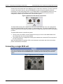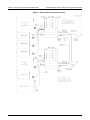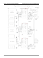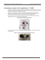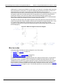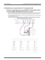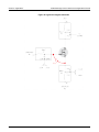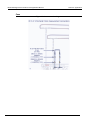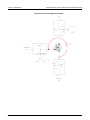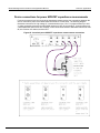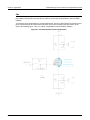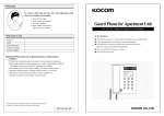
1
www.keithley.com
Model 8020
High Power Interface Panel
User’s Manual
8020-900-01 Rev. A / October 2014
*P802090001A*
8020-900-01
A Greater M easure of Confidence
A T ektronix Company
Model 8020
High Power Interface Panel
Applications Manual
© 2014, Keithley Instruments
Cleveland, Ohio, U.S.A.
All rights reserved.
Any unauthorized reproduction, photocopy, or use of the information herein, in whole or in part,
without the prior written approval of Keithley Instruments is strictly prohibited.
All Keithley Instruments product names are trademarks or registered trademarks of Keithley
Instruments. Other brand names are trademarks or registered trademarks of their respective
holders.
Document number: 8020-900-01 Rev A. / October 2014
Safety precautions
The following safety precautions should be observed before using this product and any associated instrumentation. Although
some instruments and accessories would normally be used with nonhazardous voltages, there are situations where hazardous
conditions may be present.
This product is intended for use by qualified personnel who recognize shock hazards and are familiar with the safety precautions
required to avoid possible injury. Read and follow all installation, operation, and maintenance information carefully before using
the product. Refer to the user documentation for complete product specifications.
If the product is used in a manner not specified, the protection provided by the product warranty may be impaired.
The types of product users are:
Responsible body is the individual or group responsible for the use and maintenance of equipment, for ensuring that the
equipment is operated within its specifications and operating limits, and for ensuring that operators are adequately trained.
Operators use the product for its intended function. They must be trained in electrical safety procedures and proper use of the
instrument. They must be protected from electric shock and contact with hazardous live circuits.
Maintenance personnel perform routine procedures on the product to keep it operating properly, for example, setting the line
voltage or replacing consumable materials. Maintenance procedures are described in the user documentation. The procedures
explicitly state if the operator may perform them. Otherwise, they should be performed only by service personnel.
Service personnel are trained to work on live circuits, perform safe installations, and repair products. Only properly trained
service personnel may perform installation and service procedures.
Keithley Instruments products are designed for use with electrical signals that are measurement, control, and data I/O
connections, with low transient overvoltages, and must not be directly connected to mains voltage or to voltage sources with high
transient overvoltages. Measurement Category II (as referenced in IEC 60664) connections require protection for high transient
overvoltages often associated with local AC mains connections. Certain Keithley measuring instruments may be connected to
mains. These instruments will be marked as category II or higher.
Unless explicitly allowed in the specifications, operating manual, and instrument labels, do not connect any instrument to mains.
Exercise extreme caution when a shock hazard is present. Lethal voltage may be present on cable connector jacks or test
fixtures. The American National Standards Institute (ANSI) states that a shock hazard exists when voltage levels greater than
30 V RMS, 42.4 V peak, or 60 VDC are present. A good safety practice is to expect that hazardous voltage is present in any
unknown circuit before measuring.
Operators of this product must be protected from electric shock at all times. The responsible body must ensure that operators
are prevented access and/or insulated from every connection point. In some cases, connections must be exposed to potential
human contact. Product operators in these circumstances must be trained to protect themselves from the risk of electric shock. If
the circuit is capable of operating at or above 1000 V, no conductive part of the circuit may be exposed.
Do not connect switching cards directly to unlimited power circuits. They are intended to be used with impedance-limited
sources. NEVER connect switching cards directly to AC mains. When connecting sources to switching cards, install protective
devices to limit fault current and voltage to the card.
Before operating an instrument, ensure that the line cord is connected to a properly-grounded power receptacle. Inspect the
connecting cables, test leads, and jumpers for possible wear, cracks, or breaks before each use.
When installing equipment where access to the main power cord is restricted, such as rack mounting, a separate main input
power disconnect device must be provided in close proximity to the equipment and within easy reach of the operator.
For maximum safety, do not touch the product, test cables, or any other instruments while power is applied to the circuit under
test. ALWAYS remove power from the entire test system and discharge any capacitors before: connecting or disconnecting
cables or jumpers, installing or removing switching cards, or making internal changes, such as installing or removing jumpers.
Do not touch any object that could provide a current path to the common side of the circuit under test or power line (earth)
ground. Always make measurements with dry hands while standing on a dry, insulated surface capable of withstanding the
voltage being measured.
For safety, instruments and accessories must be used in accordance with the operating instructions. If the instruments or
accessories are used in a manner not specified in the operating instructions, the protection provided by the equipment may be
impaired.
Do not exceed the maximum signal levels of the instruments and accessories, as defined in the specifications and operating
information, and as shown on the instrument or test fixture panels, or switching card.
When fuses are used in a product, replace with the same type and rating for continued protection against fire hazard.
Chassis connections must only be used as shield connections for measuring circuits, NOT as protective earth (safety ground)
connections.
If you are using a test fixture, keep the lid closed while power is applied to the device under test. Safe operation requires the use
of a lid interlock.
If a
screw is present, connect it to protective earth (safety ground) using the wire recommended in the user documentation.
symbol on an instrument means caution, risk of danger. The user must refer to the operating instructions located in the
The
user documentation in all cases where the symbol is marked on the instrument.
symbol on an instrument means caution, risk of electric shock. Use standard safety precautions to avoid personal
The
contact with these voltages.
The
symbol on an instrument shows that the surface may be hot. Avoid personal contact to prevent burns.
The
symbol indicates a connection terminal to the equipment frame.
If this
symbol is on a product, it indicates that mercury is present in the display lamp. Please note that the lamp must be
properly disposed of according to federal, state, and local laws.
The WARNING heading in the user documentation explains dangers that might result in personal injury or death. Always read
the associated information very carefully before performing the indicated procedure.
The CAUTION heading in the user documentation explains hazards that could damage the instrument. Such damage may
invalidate the warranty.
Instrumentation and accessories shall not be connected to humans.
Before performing any maintenance, disconnect the line cord and all test cables.
To maintain protection from electric shock and fire, replacement components in mains circuits — including the power
transformer, test leads, and input jacks — must be purchased from Keithley Instruments. Standard fuses with applicable national
safety approvals may be used if the rating and type are the same. Other components that are not safety-related may be
purchased from other suppliers as long as they are equivalent to the original component (note that selected parts should be
purchased only through Keithley Instruments to maintain accuracy and functionality of the product). If you are unsure about the
applicability of a replacement component, call a Keithley Instruments office for information.
To clean an instrument, use a damp cloth or mild, water-based cleaner. Clean the exterior of the instrument only. Do not apply
cleaner directly to the instrument or allow liquids to enter or spill on the instrument. Products that consist of a circuit board with
no case or chassis (e.g., a data acquisition board for installation into a computer) should never require cleaning if handled
according to instructions. If the board becomes contaminated and operation is affected, the board should be returned to the
factory for proper cleaning/servicing.
Safety precaution revision as of January 2013.
Table of Contents
Model 8020 overview ................................................................................................ 1-1
Welcome .............................................................................................................................. 1-1
Organization of manual sections .......................................................................................... 1-2
Contact information .............................................................................................................. 1-2
Unpacking and inspection .................................................................................................... 1-3
Configuring and installing the Model 8020 ............................................................. 2-1
Locating and mounting the Model 8020 ............................................................................... 2-2
Connecting to protective earth ............................................................................................. 2-4
Connecting the instrument and output interlocks ................................................................. 2-5
Connecting a single 8020 unit .............................................................................................. 2-6
Connecting 2 Model 8020 units ........................................................................................... 2-7
Connecting multiple 8020 units ............................................................................................ 2-9
Installing output cards ........................................................................................................ 2-11
Connecting to the Model 8020 ................................................................................. 3-1
Instrument panel overview ................................................................................................... 3-1
Model 8020-CVU option ....................................................................................................... 3-3
Device connections panel overview ..................................................................................... 3-3
Connections to the instrument panel ................................................................................... 3-5
Model 2611 and Model 2612 connection notes ......................................................................... 3-7
Model 2635 and Model 2636 connection notes ......................................................................... 3-7
Model 2651 connection notes ................................................................................................... 3-7
Model 4200-SCS connection notes ........................................................................................... 3-7
Using the 8020 for DC tests ..................................................................................... 4-1
Overview .............................................................................................................................. 4-1
Channel description ............................................................................................................. 4-1
Ensuring continuity in the measurement channel ................................................................ 4-3
How to insert a series resistor in the 8020 ................................................................................ 4-5
Connecting the high current channel ................................................................................... 4-6
Using connector cards to interface to the device ................................................................. 4-6
Connecting to common LO for applications > 1.5 ADC ....................................................... 4-7
Overcurrent protection ......................................................................................................... 4-8
Internal protection circuitry ................................................................................................... 4-8
Table of Contents
Model 8020 High Power Interface Panel Applications Manual
Using the Model 8020 for DC and HV C-V tests ...................................................... 5-1
Model 8020-CVU bias tee overview..................................................................................... 5-1
Bias tee theory overview ........................................................................................................... 5-2
Bias tee modes ......................................................................................................................... 5-3
I-V mode.................................................................................................................................... 5-5
C-V mode .................................................................................................................................. 5-5
C-V Hi I mode............................................................................................................................ 5-6
AC guard with DC bias mode .................................................................................................... 5-6
HV C-V measurement software ........................................................................................... 5-7
Configuring the 8020 for HV C-V measurements ................................................................ 5-8
Discharge bias tee and system capacitance ....................................................................... 5-9
Use the Model 8020-DP to discharge system capacitance ............................................... 5-10
Applications .............................................................................................................. 6-1
Device connections .............................................................................................................. 6-1
Equipment options (all examples) ........................................................................................ 6-2
Software ............................................................................................................................... 6-2
2-terminal device connections for I-V measurements .......................................................... 6-3
Using the Model 2657A ............................................................................................................. 6-3
Using the Model 2600 / 4200 .................................................................................................... 6-4
Using the Model 2651A ............................................................................................................. 6-5
3-terminal device connections for I-V measurements .......................................................... 6-6
Off-state characterization of a power MOSFET using the Model 2657A and
Series 2600B / 4200-SMU instruments (up to 3 kV).................................................................. 6-6
Off-state characterization of a power MOSFET using the Series 2600B / 4200 SMU
instruments (up to 200 V) .......................................................................................................... 6-7
On-state characterization of a power MOSFET using the Model 2651A and
Series 2600 / 4200 SMU instruments (up to 100 A pulse) ........................................................ 6-8
On-state characterization of a power MOSFET using 2 Series 2600 / 4200 SMU
instruments (up to 10 A pulse) .................................................................................................. 6-9
2-terminal device connections for C-V measurements ...................................................... 6-10
Open and short compensation ................................................................................................ 6-12
3-terminal device connections for C-V measurements ...................................................... 6-12
Overview and theory ............................................................................................................... 6-13
Instrument connections for power MOSFET capacitance measurements............................... 6-15
Device connections for power MOSFET capacitance measurements..................................... 6-25
Open and short compensation ................................................................................................ 6-26
Measurement considerations .................................................................................. 7-1
Introduction .......................................................................................................................... 7-1
2-wire (local) vs. 4-wire (remote) sensing for DC I-V measurements .................................. 7-1
Optimizing cables and connections for low current DC measurements .............................. 7-3
Suppressing device oscillations for DC and pulsed DC measurements .............................. 7-3
Optimizing connections for high current DC pulses ............................................................. 7-4
Optimizing cables and connections for high voltage C-V measurements ........................... 7-4
Model 8020 High Power Interface Panel Applications Manual
Frequently asked questions..................................................................................... 8-1
Why does my instrument generate an interlock error / warning? ........................................ 8-1
Why are my DC current measurements unstable? .............................................................. 8-2
Can I break the parallel connection of the high-current SMUs? .......................................... 8-2
Can I operate the 8020 with the top cover off? .................................................................... 8-2
Why is the pulse rising edge so slow for my SMU? ............................................................. 8-3
Why don't I get a signal at the output? My measurements appear to be an open circuit. ... 8-3
Why are my contact check measurements failing when the SMUs are connected
to the high voltage and 200 V channels? ............................................................................. 8-3
Why is the high current LO terminal not connected to the Common LO terminal
of the 8020? ......................................................................................................................... 8-3
Index ............................................................................................................................. 1
Table of Contents
Section 1
Model 8020 overview
In this section:
Welcome .................................................................................. 1-1
Organization of manual sections .............................................. 1-2
Contact information .................................................................. 1-2
Unpacking and inspection ........................................................ 1-3
Welcome
Thank you for choosing a Keithley Instruments product. The Model 8020 High Power Interface Panel
provides a highly accurate, flexible, and easy to use interface between the Keithley Instruments
®
SourceMeter instruments and a variety of semiconductor probe stations or custom test fixtures.
The Model 8020 High Power Interface Panel has six measurement pathways accommodating 3 kV,
200 V, and 100 A measurements. You can configure five of the pathways with a variety of output
connector types to match your probe station. You can configure four pathways with the optional bias
tees. This provides high voltage C-V measurements on up to 4 pins of the device under test.
The Model 8020 comes with a selection of resistors that you can install to provide stability and extra
protection to the device.
Additionally, the Model 8020 High Power Interface Panel offers the following:
•
•
A common LO reference
•
•
•
A variety of connector types
•
Optional transient overcurrent protection on the 200 V channels
Overvoltage protection for all 200 V channels, ideal for device testing configurations using 200 V
SMUs and higher voltage SMUs
A single interlock interface for multiple instruments
An interface for adding series resistor elements for measurement stability and absolute current
limit
Section 1: Model 8020 overview
Model 8020 High Power Interface Panel Applications Manual
Organization of manual sections
The first part of this user manual provides general information that helps you set up, install, and make
connections to the high power interface panel.
The sections after the general sections provide information that helps you use the Model 8020 with
specific SourceMeter Instruments. This information includes applications that can help you set up
your tests.
The last part of the user manual provides maintenance and troubleshooting information. It also
provides references to additional resources.
Bookmarks for each section of this manual are provided in the PDF. The manual sections are also
listed in the Table of Contents located at the beginning of the manual.
®
®
®
For more information about bookmarks, see Adobe Acrobat or Reader help.
Contact information
If you have any questions after you review the information in this documentation, please contact your
local Keithley Instruments office, sales partner, or distributor, or call Keithley Instruments corporate
headquarters (toll-free inside the U.S. and Canada only) at 1-800-935-5595, or from outside the U.S.
at +1-440-248-0400. For worldwide contact numbers, visit the Keithley Instruments website
(http://www.keithley.com).
1-2
8020-900-01 Rev. A / October 2014
Model 8020 High Power Interface Panel Applications Manual
Section 1: Model 8020 overview
Unpacking and inspection
Each Model 8020 was carefully inspected electrically and mechanically before shipment.
After you unpack all items from the shipping carton, check for any obvious signs of physical damage
that may have occurred during transit. Report any damage to the shipping agent immediately. Save
the original packing carton for possible future shipment.
See the following 2 graphics and accompanying table to verify that you have received all accessories
and documentation.
Depending on your system configuration, your shipping carton may contain additional accessories
and documentation.
What you should have received
Figure 1: Hardware accessories
Figure 2: Documentation
Graphic Item number
number
Quantity
shipped
Description
1
2
8020-SNS-X
CS-1195-2
2
1
8 Pin to 2 Pin Phoenix Cables
2-Pin Phoenix Connector for 2651A Sense
3
8020-RES-KIT
4
CA-568-120
1
2
5
8020-ILC-UNT
1
Unterminated Interlock Cable
6
8020-ILC-S
1
Interlock Expansion Termination Plug
8020-900-01 Rev. A / October 2014
1
HV-Rated Resistors
Safety Earth Ground Cable Assembly
1-3
Section 1: Model 8020 overview
1-4
Model 8020 High Power Interface Panel Applications Manual
Graphic Item number
number
Quantity
shipped
Description
7
PA-853
1
Safety Standards Conformance Information
8
PA-935
1
Environmental Disclosure Report (Instruments / Systems)
9
PA-1073
1
Statement of Compliance
10
PA-1042
1
2-Pin Female (Plug Housing) Termination Block PA
11
071327800
1
Interlock Expansion Termination Plug PA
12
071327300
1
Unterminated Interlock Cable PA
13
071338400
1
Phoenix Connector for 2651A Sense PA
14
071323500
1
HV-Rated Resistors
8020-900-01 Rev. A / October 2014
Section 2
Configuring and installing the Model 8020
In this section:
Locating and mounting the Model 8020.................................... 2-2
Connecting to protective earth.................................................. 2-3
Connecting the instrument and output interlocks...................... 2-5
Connecting a single 8020 unit .................................................. 2-6
Connecting 2 Model 8020 units ................................................ 2-7
Connecting multiple 8020 units ................................................ 2-9
Installing output cards............................................................. 2-11
Section 2: Configuring and installing the Model 8020
Model 8020 High Power Interface Panel Applications Manual
Locating and mounting the Model 8020
The Model 8020 is designed to be installed on a probe station or as close as possible to a probe
station to ensure optimal C-V and DC measurements. See the below figures for unit dimensions and
mounting specifications.
The fully populated weight of the Model 8020 is 5.7 kg (12.5 lbs.).
Figure 3: Model 8020 mounting specifications, instrument and device panels
2-2
8020-900-01 Rev. A / October 2014
Model 8020 High Power Interface Panel Applications Manual
Section 2: Configuring and installing the Model 8020
Figure 4: Model 8020 mounting specifications, unit sides
8020-900-01 Rev. A / October 2014
2-3
Section 2: Configuring and installing the Model 8020
Model 8020 High Power Interface Panel Applications Manual
Connecting to protective earth
The Model 8020 must be connected to protective earth (safety ground) using both of the
supplied green-yellow ground cable (Model CA-568-120).
1. Connect one lugged end of both of the supplied Model CA-568-120 ground cables to any
combination of the 4 screw terminals on either panel side of the Model 8020. See the below 2
figures.
2. Connect the other 2 lugged ends of the ground cables to protective earth (safety ground).
Figure 5: Instrument side connections to protective earth
Figure 6: Device side protective earth terminals
2-4
8020-900-01 Rev. A / October 2014
Model 8020 High Power Interface Panel Applications Manual
Section 2: Configuring and installing the Model 8020
Connecting the instrument and output interlocks
The 8020 has an interlock system to control the interlock of 26xx and 4200 instruments. On the
instrument connections side of the Model 8020, there are 6 26xx interlock 3-pin connectors and one
circular 3-pin connector for the 4200 interlock. See the below graphic.
Use Keithley CA-558 and 236-ILC-3 interlock cable assemblies to connect to Series 2600 and 4200sCS instruments. For proper interlock functionality, any instruments connected to the interlock must
be powered-on or else disconnected from the interlock.
For proper interlock functionality, any instruments connected to the interlock must be powered on or
else disconnected from the interlock.
Figure 7: Instrument side interlock connectors
For proper interlock functionality, any instruments connected to the interlock must be powered on or
else disconnected from the interlock.
The Model 8020 also has internal interlock circuitry to detect whether the top cover of the 8020 is
installed or not. When the 8020 top cover is installed, the external interlock system controls the state
of the interlock. However, when the 8020 top cover is removed, the interlock is disengaged
regardless of the state of the external interlock.
An interlock connection is required when a 2657 Series instrument is connected and a
Series 2600/4200 SMU is used to make measurements beyond 20 V.
8020-900-01 Rev. A / October 2014
2-5
Section 2: Configuring and installing the Model 8020
Model 8020 High Power Interface Panel Applications Manual
On the device connections side of the 8020 there are 2 circular 4-pin connectors, The OUT connector
is used for the system interlock, and the EXPANSION connector is used for extending interlock
functionality in a test configuration with 2 or more Model 8020s. The EXPANSION connector is also
used with the supplied model 8020-ILC-S Interlock Expansion Termination Plug when the test
configuration contains only one Model 8020. See the below graphic.
Figure 8: 8020 device side interlock connections
The Model 8020 interlock OUT connector on the device connections side of the unit is designed for
use with the supplied 8020-ILC-UNT interlock to unterminated cable. The interlock enables the high
voltage outputs of the connected instruments when the normally-open switch at the DUT access point
is closed.
The Model 8020 interlock is satisfied only when:
•
The top cover to the 8020 is correctly installed and any top covers to other Model 8020s in the
test configuration are also correctly installed
•
The system interlock is engaged (all normally-open switches are closed at DUT access points of
the test configuration)
When the 8020 interlock is satisfied, LEDs on the instrument connections and device connections
panels of the 8020 are illuminated.
Connecting a single 8020 unit
For a test configuration using a single Model 8020, the 8020-ILC-S Interlock Expansion Termination
Plug must be connected to the EXPANSION jack to enable interlock functionality. See the below
graphic.
Figure 9: 8020 interlock plug installed
2-6
8020-900-01 Rev. A / October 2014
Model 8020 High Power Interface Panel Applications Manual
Section 2: Configuring and installing the Model 8020
Instrument-side and device-side connections for a single Model 8020 are shown in the below figure.
Figure 10: 8020 interlock connections (single unit)
Connecting 2 Model 8020 units
The 8020 High Power Interface Panel can be connected with another 8020 unit when you have a
need for more than 1 Model 2657 in the test configuration or more than 3 Series 2600 or 4200 SMUs.
The Model 8020 allows you to expand the common LO/SLO reference signal as well as the interlock
system to a second Model 8020. This ensures that the instruments have a common LO reference and
are triggered from a common interlock.
Both the common LO/SLO signals and the interlock signal of the Model 8020 can be daisy-chained
between units. Expansion is via the common SLO/LO standard triaxial, interlock OUT, and
EXPANSION connectors on the device side of the 8020 units. The system interlock and either of the
8020 units' top cover interlocks will enable or disable the interlock feature for all connected
instruments.
The following example diagram uses 2 8020s. One additional triaxial cable is used in this instance.
Additionally, note that the 8020-ILC-S Interlock Expansion Termination Plug must be connected to the
interlock EXPANSION connector of the second unit.
8020-900-01 Rev. A / October 2014
2-7
Section 2: Configuring and installing the Model 8020
Model 8020 High Power Interface Panel Applications Manual
Figure 11: 8020 interlock connections (2 units)
2-8
8020-900-01 Rev. A / October 2014
Model 8020 High Power Interface Panel Applications Manual
Section 2: Configuring and installing the Model 8020
Connecting multiple 8020 units
More than 2 8020 units may be connected so that any of the connected units' interlocks will enable or
disable the interlock feature for all connected instruments. The common LO/SLO may also be
maintained with this configuration, as well. The connections are the same as those used for 2 Model
8020 units, with 2 differences:
•
An 8020-1-ILC expansion cable connects the first unit in the series' interlock EXPANSION
connector to the interlock OUT of the next 8020. This connection is repeated for all successive
8020 units.
•
The common LO/SLO signal is maintained by connecting the second unit's SLO/LO channel to
the next unit's common LO/SLO expansion. This connection is repeated for all successive 8020
units. When the common LO current exceeds 1.5 ADC, please use the LO binding post to link the
LO terminals of the Model 8020 interface panels. See Connecting to common LO for applications
>1.5 ADC (see "Connecting to common LO for applications > 1.5 ADC" on page 4-7).
The interlock EXPANSION connector of the final 8020 unit must be terminated with the 8020-ILC-S
Interlock Expansion Termination Plug.
See the following diagram for a test array using 3 Model 8020 units.
8020-900-01 Rev. A / October 2014
2-9
Section 2: Configuring and installing the Model 8020
Model 8020 High Power Interface Panel Applications Manual
Figure 12: 8020 interlock connections (multiple units)
2-10
8020-900-01 Rev. A / October 2014
Model 8020 High Power Interface Panel Applications Manual
Section 2: Configuring and installing the Model 8020
Installing output cards
The following optional connector cards are available for use with the Model 8020:
•
•
•
•
8020-AHV: Kelvin Agilent HV Triaxial
8020-SHV: Kelvin SHV
8020-KHV: Kelvin Keithley HV Triaxial
8020-STC: Kelvin Standard Triaxial
Installation of the connector cards requires removal of the 8020's top cover and output module guide
retainer. Refer to the following graphic and instructions.
Figure 13: Model 8020 output card installation
1. Remove the top cover of the Model 8020 using the four thumb screws.
2. Using a slot screwdriver, loosen the three screws on the output module guide retainer and set it
aside.
3. Slide the output card into a vacant card slot as shown in the above figure. Ensure that the captive
screw on the card is backed-out far enough so that it does not catch on the output card side rail.
While an HV card will fit in any available card slot, the Model 8020-STC card will not fit in the HV
output channel (right-most card slot on the device connections side of the unit). Only output cards
with a maximum voltage rating of 3 kV or higher can be used in the HV output channel.
4. Using a slot screwdriver, tighten the screw at the lower-left corner of the output card.
5. Place the output module guide retainer back onto the unit chassis and tighten the three screws.
6. Reinstall the top cover of the Model 8020.
8020-900-01 Rev. A / October 2014
2-11
Section 3
Connecting to the Model 8020
In this section:
Instrument panel overview........................................................ 3-1
Model 8020-CVU option ........................................................... 3-3
Device connections panel overview ......................................... 3-3
Connections to the instrument panel ........................................ 3-5
Instrument panel overview
The input/output terminals of the Model 8020 are rated for connection to circuits rated
Installation Category I only, with transients rated less than 1500 V peak above the rated
input. Do not connect the Model 8020 terminals to CAT II, CAT III, or CAT IV circuits.
Connection of the terminals to circuits higher than CAT I can cause damage to the
equipment or expose the operator to hazardous voltage.
Instrument connections are made to the instrument panel of the Model 8020.
The instrument panel of the Model 8020 (with 8020-CVU option installed) is shown below.
Descriptions of the connections are provided after the graphic.
Figure 14: Model 8020 Instrument Panel, 8020-CVU option installed
The Model 2657 (high voltage) connectors provide sense HI, HI, LO, and
sense LO input connections for the Model 2657 instruments.
Connections are as follows:
•
SHI = Sense HI
•
HI = HI
•
LO, SLO = LO, sense LO
Section 3: Connecting to the Model 8020
Model 8020 High Power Interface Panel Applications Manual
The Model 2600/4200#1 connectors provide sense HI, HI, LO, and sense
LO input connections for the Model 2600/4200 instruments. These
connections are intended for use with 200 V-compatible 2600/4200 Series
instruments.
Connections are as follows:
•
SHI = Sense HI
•
HI = HI
•
LO, SLO = LO, sense LO
The Model 2600/4200#2 connectors provide sense HI, HI, LO, and sense
LO input connections for the Model 2600/4200 instruments. These
connections are intended for use with 200 V-compatible 2600/4200 Series
instruments.
Connections are as follows:
•
SHI = Sense HI
•
HI = HI
•
LO, SLO = LO, sense LO
The Model 2600/4200#3 connectors provide sense HI, HI, LO, and sense
LO input connections for the Model 2600/4200 instruments. These
connections are intended for use with 200 V-compatible 2600/4200 Series
instruments.
Connections are as follows:
•
SHI = Sense HI
•
HI = HI
•
LO, SLO = LO, sense LO
The INTERLOCK connectors provide and enable interlock functionality for
the Model 26XX series of instruments
An illuminated LED beneath the ENGAGED label indicates that the
interlock is engaged and active.
The 2651 (high current) #1 connectors provide Model 2651 input
connections for source LO, source HI, LO, and HI. Connections are as
follows:
•
SLO = Sense LO
•
SHI = Sense Hi
•
LO = LO
•
HI = HI
3-2
8020-900-01 Rev. A / October 2014
Model 8020 High Power Interface Panel Applications Manual
Section 3: Connecting to the Model 8020
The 2651 (high current) #2 connectors provide Model 2651 input
connections for source LO, source HI, LO, and HI. Connections are as
follows:
•
SLO = Sense LO
•
SHI = Sense Hi
•
LO = LO
•
HI = HI
Ground screws for connections to protective earth (safety ground).
The HV bias tee input connectors provide SMA input connections for AC
HV CUR (force) and HV POT (sense). These connectors are designed for
connection to a CV-measurement instrument.
Model 8020-CVU option
The AC guard SMA connector provides an AC guard for connection to a
bias tee. This connector is only present with the integrated 8020-CVU bias
tee option.
The bias tee input connectors #1, #2, and #3 provide SMA input
connections for AC CUR (force) and POT (sense). These connectors are
designed for connection to a CV-measurement instrument.
The connectors are only present with the integrated 8020-CVU bias tee
option.
Device connections panel overview
Device under test connections are made to the device connections panel of the Model 8020.
The device panel of the Model 8020 is shown below. Descriptions of the device panel connections
are provided after the graphic.
Figure 15: Model 8020 device connections panel
8020-900-01 Rev. A / October 2014
3-3
Section 3: Connecting to the Model 8020
Model 8020 High Power Interface Panel Applications Manual
The connectors provide the combined output of the Model 2651. You can
use these connections to connect the Model 8020 to 1 or 2 Model 2651
units.
Connections are as follows:
•
SLO = Sense LO
•
SHI = Sense HI
•
LO = LO
•
HI = HI
The Common LO, SLO expansion triaxial connector provides an additional
terminal for common LO and SLO. This is useful when connecting 2 or
more Model 8020 units.
The OUT interlock connector provides an interface to control the interlock
of Series 26XX and 4200 instruments.
The EXPANSION interlock is used in a test configuration system using 2
or more Model 8020 units.
The ENGAGED LED illuminates when the interlock is engaged and
active.
The LO connector provides a common LO connection. This jack may be
connected to the chassis ground lug connector (see below) via the ground
lug link.
This connector is useful when LO may carry more current than can be
passed through the LO triaxial connector. This connection supports up to
4.5 ADC or 10 A fuse.
The chassis ground lug connector provides a grounding point for the
chassis of the Model 8020. You can connect this lug to the common LO
jack with the supplied connector link.
Five connector card slots are available on the device panel side of the
Model 8020. The card slot in which the connector card is installed
corresponds to a set of connections on the instrument side of the 8020.
For more information on this topic, see Using the 8020 for DC tests (see
"Channel description" on page 4-1).
3-4
8020-900-01 Rev. A / October 2014
Model 8020 High Power Interface Panel Applications Manual
Section 3: Connecting to the Model 8020
Connections to the instrument panel
This section describes the connections you can make to the instrument connections panel of the
Model 8020 High Power Interface Panel.
The ground wires must be attached to a known protective earth (safety ground) before
powering on instruments. Failure to attach the ground wires to a known protective earth
may result in electric shock.
Do not convert triaxial cables to BNC cables. Using BNC cables will remove protection from
SourceMeter Instrument voltages and may result in instrument damage. You must use
triaxial cables for connections to the Model 8020.
8020-900-01 Rev. A / October 2014
3-5
Section 3: Connecting to the Model 8020
Model 8020 High Power Interface Panel Applications Manual
Figure 16: Connections to the 8020 instrument panel
3-6
8020-900-01 Rev. A / October 2014
Model 8020 High Power Interface Panel Applications Manual
Section 3: Connecting to the Model 8020
Model 2611 and Model 2612 connection notes
The Model 8020 includes overvoltage protection circuitry for the Model 2611 and 2612 SMUs. In a
test configuration having both a 200 V SMU and a Model 2657 connected to the DUT, this circuitry
protects the SMUs from high voltage from the Model 2657.
The LO terminal is connected to chassis ground if you connect the Model 2611 or Model 2612 to the
Model 8020 through the Model 2600-TRX SMU Connector.
Model 2635 and Model 2636 connection notes
The Model 8020 includes overvoltage protection circuitry for the Model 2635 and 2636 SMUs. In a
test configuration having both a 200 V SMU and a Model 2657 connected to the DUT, this circuitry
protects the SMUs from high voltage from the Model 2657.
Model 2651 connection notes
The Model 8020 connects up to 2 Model 2651 instruments in parallel for up to 100 A pulsed current
output.
There is no safety interlock on the Model 2651A — the safety interlock is not necessary because
output voltage of the Model 2651A is below hazardous levels. The CA-558-2 cable is shown here in
case you want to use Output Enable to shut off the output when the Model 8020 top cover is
removed. To activate Output Enable, refer to the Model 2651A Reference Manual. Output Enable
can be activated using the front panel or by remote control.
Model 4200-SCS connection notes
Model 42XX-SMUs
The Model 8020 includes internal protection circuitry for the Model 42XX-SMU series of source
measurement units. In a test configuration having both a 200 V SMU and a Model 42XX-SMU
connected to the DUT, this circuitry protects the SMUs from high voltage from the Model 2657.
Model 4210-CVU
When the Model 8020-CVU option is installed, the Model 4210-CVU Capacitance-Voltage Instrument
connects to the CUR and POT SMA connectors, which are the AC inputs of the bias tee. Please refer
to Section 5 (see "Bias tee theory overview" on page 5-2) for more detail on using the 8020-CVU bias
tee option.
8020-900-01 Rev. A / October 2014
3-7
Section 4
Using the 8020 for DC tests
In this section:
Overview .................................................................................. 4-1
Channel description .................................................................. 4-1
Ensuring continuity in the measurement channel ..................... 4-3
Connecting the high current channel ........................................ 4-6
Using connector cards to interface to the device ...................... 4-6
Connecting to common LO for applications > 1.5 ADC ............ 4-7
Overcurrent protection .............................................................. 4-8
Internal protection circuitry ....................................................... 4-8
Overview
The Model 8020 High Power Interface Panel offers a convenient way to combine SMU instruments
and C-V instruments to perform a variety of DC I-V tests and HV C-V tests. This section will discuss
the configuration of the 8020 to make DC I-V tests. See Model 8020-CVU bias tee overview (on page
5-1) for more information.
Channel description
The following are the Model 8020 DC test channels:
•
•
•
•
High voltage channel
200 V channels #1, #2, and #3
Common LO channel
High current channel
For DC measurements, the high voltage channel passes the high voltage signal at the instrument
connections panel directly to the designated connector card at the device connections panel.
The 200 V channels incorporate overvoltage protection; when used in conjunction with a high voltage
SMU instrument during device testing, a breakdown at the device will not damage the SMU
instruments routed through the 200 V channels.
The common LO channel (see the below graphic) combines the sense LO of all channels to a
common sense LO terminal and combines LO of the high voltage and 200 V channels to a common
LO terminal. These common terminals are also available via a binding post connector and a 3-lug
triaxial connector on the device connection panel of the Model 8020. The binding post connector is
useful when DC current above 1.5 A travels via common LO. The 3-lug triaxial connector is useful for
expanding continuity to other 8020 units in a test configuration. See Configuring and installing the
8020 (see "Connecting 2 Model 8020 units" on page 2-7) for detailed information on connecting
multiple 8020 units.
Section 4: Using the 8020 for DC tests
Model 8020 High Power Interface Panel Applications Manual
Figure 17: 8020 common LO/SLO channel (top shield view)
Common LO and Sense LO are clamped to 42 V from chassis and can be tied to chassis using the
binding posts and link at the device connections panel of the instrument. See the below graphic.
Figure 18: LO connector connected to chassis ground lug
The high current channel can accept up to two Model 2651A 50 A SMU instruments and places these
instruments in parallel to allow up to 100 A pulses. Connectors for this model on both the instrument
and device connection panels are Phoenix screw terminal. This makes it easy to connect banana or
unterminated cables to the connector of your choice. The channel resistance is very low, so 50 A DC
and 100 A pulses can be transmitted with little voltage drop across the Model 8020.
4-2
8020-900-01 Rev. A / October 2014
Model 8020 High Power Interface Panel Applications Manual
Section 4: Using the 8020 for DC tests
Ensuring continuity in the measurement channel
To ensure channel continuity for DC I-V tests on the high voltage and 200 V channels, install a short
or resistor in the DC path between nodes 1A and 2 on the 8020 main board. See the below graphic
as well as How to insert a series resistor in the 8020 (on page 4-4). The 8020-RES-KIT resistor kit
supplied with the Model 8020 includes a 0 Ω resistor, among several other resistor values ranging
from 20 Ω to 1 MΩ.
Figure 19: Resistor installed between nodes 1a and 2
Some high-gain devices are prone to oscillation during testing and a series resistor is useful for
suppressing such oscillations. You may also use series resistors to limit the absolute current from the
SMU instrument, such as for a breakdown voltage measurement. The wide variety of resistor values
in the Model 8020-RES-KIT resistor kit is useful for suppressing oscillations or enforcing an absolute
current limit. You will need to experiment with different resistor values to identify the best resistance
value for your application.
The following schematics illustrate the circuits created when series resistors are installed at a
pathway node on the 8020 main board.
Figure 20: Resistor installed for on-state characteristic measurements
8020-900-01 Rev. A / October 2014
4-3
Section 4: Using the 8020 for DC tests
Model 8020 High Power Interface Panel Applications Manual
Figure 21: Resistor installed for off-state characteristic measurements
For more information on the applications/measurement conditions that benefit from a series resistor,
see Section 7, Measurement considerations (see "Introduction" on page 7-1).
When the series resistance is greater than 0 Ω, disconnect sense HI of the instrument at the device
connections panel. The instrument can remain in remote sense, as remote sense connections are
maintained to node 1a.
4-4
8020-900-01 Rev. A / October 2014
Model 8020 High Power Interface Panel Applications Manual
Section 4: Using the 8020 for DC tests
How to insert a series resistor in the 8020
Before installing cards or components, make sure you remove all electrical connections to
the test fixture and follow the discharge procedure outlined in the next section of this
manual.
The following instructions explain how to install a resistor in a path of the Model 8020.
1. Remove any external power that is connected to the interface through connected devices or
devices under test (DUTs).
2. Loosen the 4 thumb-screws securing the top cover to the unit.
3. Remove the top cover and set aside.
4. Place the series resistor on the Model 8020 motherboard nodes according to your application.
See the following conditions and graphic.
Without 8020-CVU bias tee option
•
Place the series resistor between nodes 1a and 2.
With 8020-CVU bias tee option
•
•
For a static DC signal on the gate, place the series resistor between nodes 1b and 2.
For a pulsed DC signal on the gate, place the series resistor between nodes 1a and 2.
Figure 22: Model 8020 motherboard resistor between nodes 1 and 2
5. Tighten the screws that secure the resistor leads.
6. Bend the exposed leads back toward the resistor body.
The resistor lead must point back toward the resistor body to reduce the possibility of current
leakage from the bias tees in the adjacent 8020-CVU (if installed).
7. Replace the unit top cover.
8. Tighten the 4 thumb screws at the corners of the top cover.
9. Reconnect any external connections to the Model 8020.
8020-900-01 Rev. A / October 2014
4-5
Section 4: Using the 8020 for DC tests
Model 8020 High Power Interface Panel Applications Manual
Connecting the high current channel
The LO of the high current channel is isolated from the common LO of the Model 8020. This
eliminates the possibility of voltage errors on the 200 V channels due to high current pulses. For
optimal voltage measurement on all connected SMU instruments, keep the high current force
connections, both HI and LO, isolated from connections to other SMU instruments. For multi-terminal
devices, tie together the common LO to the LO of the high current channel at the device terminal or
as close as possible to the device terminal.
Using connector cards to interface to the device
The connector cards interface each instrument or measurement channel to the connector or terminal
at the device under test. Each connector card is designed for Kelvin connectors and thus has
separate force and sense connections. There are several connector cards available.
All card slots must have connector cards installed or the Model 8020-BLK blank card
faceplate installed.
Refer to the Model 8020 specifications for a complete list of compatible connector cards. The high
voltage channel is keyed so that only high voltage connector cards or cards with ratings of at least 3
kV can be installed. To install a new or different connector card, refer to Section 2, Configuring and
installing the 8020.
For optimal accuracy in making low current measurements, use triaxial connector cards such as the
Keithley Instruments Model 8020-KHV, Model 8020-STC or Model 8020-AHV.
4-6
8020-900-01 Rev. A / October 2014
Model 8020 High Power Interface Panel Applications Manual
Section 4: Using the 8020 for DC tests
Connecting to common LO for applications > 1.5 ADC
Some connector cards are not rated for the full current capability of the Model 8020. This is especially
important to remember as you consider the connector card for the Common LO channel. Refer to the
connector card specifications for specific current limits.
The common LO channel is a sum of the LO terminals from the high voltage and 200 V SMU
instruments. The maximum current limit of the common LO channel is 4.5 A DC, but this is only
available at the binding post at the device connections panel. See the graphic below.
If the sum of the DC current in the high voltage and 200 V channels exceeds the connector card
specification, access common LO from the LO binding post.
Figure 23: 8020 common LO binding post
The LO output can also be connected to ground via the link attached to the chassis ground lug. See
the below graphic.
Figure 24: LO connector connected to chassis ground lug
8020-900-01 Rev. A / October 2014
4-7
Section 4: Using the 8020 for DC tests
Model 8020 High Power Interface Panel Applications Manual
Overcurrent protection
Each connector card contains a 10 A fuse to allow maximum pulse current for each SMU instrument.
Removing this fuse enables transient overcurrent protection. This transient overcurrent protection is
useful for protecting probes and other sensitive interface hardware at the device under test.
Transient overcurrent protection is only available on the 200 V channels within the Model 8020. When
using a connector card in the HV channel, be sure that the 10 A fuse is installed.
Although each SMU instrument has a programmed current limit, it is possible to exceed this limit for
very brief periods, especially during events in which there is a very large change in device
impedance. Additionally, high currents may be present in the test system due to rapid discharge of
cable and system capacitance, which may be at hundreds to thousands of volts. The transient
overcurrent protection is useful for suppressing such current transients.
The transient overcurrent protection is designed for use in low-current applications. It is not intended
for applications in which there is continuous current greater than 100 mA, as such current could result
in voltage errors. Additionally, the overcurrent protection will degrade the pulse shape of pulses
output from the SMU instrument; bypass the overcurrent protection in these cases by installing the 10
A fuse on the connector card.
Internal protection circuitry
The Model 8020 includes overvoltage protection circuitry that protects instruments in applications
where a device breakdown or other potential failure could connect the high-voltage output of a Model
2657 high-voltage SMU to a lower voltage SMU.
The Model 8020 includes overvoltage protection circuitry for the Models 2611, 2612, 2635, 2636, and
4200-SCS SMUs. The protection circuitry is automatically connected whenever you make
connections between the Model 8020 and these SMUs.
4-8
8020-900-01 Rev. A / October 2014
Section 5
Using the Model 8020 for DC and HV C-V tests
In this section:
Model 8020-CVU bias tee overview ......................................... 5-1
HV C-V measurement software ................................................ 5-7
Configuring the 8020 for HV C-V measurements ..................... 5-7
Discharge bias tee and system capacitance ............................ 5-9
Use the Model 8020-DP to discharge system capacitance .... 5-10
Model 8020-CVU bias tee overview
The Model 8020-CVU bias tee is a factory-installed option for the Model 8020 High Power Interface
Panel. The 8020-CVU bias tees couple the DC bias from a SMU instrument with the AC
measurement of an impedance measurement instrument to enable capacitance-voltage (C-V)
measurements with DC bias up to 3000 V and AC measurement frequencies from 10kHz to 2MHz.
This bias tee option is intended for use with the Keithley Series 26xx and 4200 SMU instruments and
the Keithley Model 4210-CVU C-V instrument.
The 8020-CVU includes four bias tees. A bias tee is installed in circuit with the high voltage SMU
channel and each of the 200 V SMU channels of the Model 8020, as shown in the below figure. Using
all four bias tees enables C-V measurements with DC bias at up to four device terminals and allows
complete characterization of circuit-level and component-level capacitance parameters of power
devices without connection changes at the device.
When the 8020-CVU is installed, the front panel contains nine SMA connectors: Four pairs of SMA
connectors that are the AC inputs to the four bias tees, and an AC guard connection. The next figure
shows the 8020 with the bias tees installed. The AC inputs for each bias tee are labeled POT and
CUR to represent the sense and force terminals of the 4210-CVU, respectively. However, high
voltage C-V measurements done through the 8020 are two-wire (local sense) measurements and the
two AC inputs for each bias tee are shorted together in the bias tee. Therefore, for high voltage
capacitance measurements, Kelvin connections are terminated at the instrument side of 8020.
When measuring capacitance through the Model 8020, disconnect the SMU Sense HI and Sense LO
cables at the device connections panel of the Model 8020.
Section 5: Using the Model 8020 for DC and HV C-V tests
Model 8020 High Power Interface Panel Applications Manual
Figure 25: Model 8020 instrument connections panel
Bias tee theory overview
The 8020-CVU bias tees combine C-V measurement with DC bias while isolating the C-V instrument
and SMU instrument from each other. A typical bias tee uses a capacitor to isolate the C-V instrument
from interfering with DC measurements and an inductor is used in series with the SMU instrument to
isolate the SMU from interfering with AC measurement (see the following figure).
Figure 26: 8020 typical coaxial bias tee block diagram
5-2
8020-900-01 Rev. A / October 2014
Model 8020 High Power Interface Panel Applications Manual
Section 5: Using the Model 8020 for DC and HV C-V tests
Isolating the C-V instrument and SMU from each other is not foolproof or completely stable across the
range of frequencies used by the C-V instrument. Balancing the performance of DC I-V and AC C-V
signal path needs can result in compromises in the usable frequency range for AC C-V
measurements and the minimum current sensitivity for DC low current measurements. Also, bias tees
are typically coaxial and not triaxial, which further compromises low current DC measurements by
removing the ability to use a driven DC guard to shunt extraneous leakage currents. Such
performance compromises often prompt users to remove the bias tee before DC I-V characterization.
These measurement setup changes are time-consuming and prone to error.
The 8020-CVU bias tee option has multiple operation modes that optimize the performance for each
measurement type while nearly eliminating measurement configuration changes between DC I-V and
C-V measurements. Additionally, the bias tees are fully guarded and configured for triaxial
connections so that the low current DC measurements may be performed through the bias tee (see
the following figure).
Figure 27: 8020-CVU single bias tee block diagram
Bias tee modes
Each Model 8020-CVU bias tee can be configured in one of four modes:
1.
2.
3.
4.
IV mode (see "I-V mode" on page 5-5)
C-V mode (on page 5-5)
CV Hi I mode (see "C-V Hi I mode" on page 5-6)
AC guard with DC bias mode (on page 5-6)
Configure the bias tee mode by programming the DC bias voltage provided by the C-V instrument at
the AC bias tee input. The Model 4210-CVU capacitance-voltage instrument has built-in DC bias
capability that can be utilized to configure the bias tee mode. In the Model 8020-CVU bias tee option,
the 4210-CVU DC bias is not available to the DUT, and may only be used as a control voltage. For
more information on Keithley software that automatically controls the bias tee mode, see the HV C-V
measurement software (on page 5-7) topic. The next table provides an overview of the four available
bias tee modes.
8020-900-01 Rev. A / October 2014
5-3
Section 5: Using the Model 8020 for DC and HV C-V tests
Model 8020 High Power Interface Panel Applications Manual
Table: Four available bias tee modes
Mode
Application
Block
diagram
I-V mode (on
page 5-5)
Use for best DC low current
measurement performance.
Ideal for any DC
measurements made with the
8020-CVU installed. DC
currents up to 1 A are
permissible in this mode.
Example tests: Idss, Vds-Id
Use for C-V measurements
with a maximum DC bias
current of 100 µA. Frequency
range of 10 kHz - 2 MHz
2
possible .
Example tests: Ciss, Coss
Use for C-V measurements
with a maximum DC bias
current of 1 A. Frequency
range of ~100 kHz - 2 MHz
3
possible . Not for low current
DC measurements.
Example tests: Ciss, Coss
Use for measuring
capacitance between two
terminals of a device with
three or more terminals. This
mode guards capacitance to
third terminal by shunting AC
current away from the AC
measurement circuit.
Example tests: Cgd, Cgs,
Cds
I-V mode
0 V (default Open
(on page 5- state)
5)
C-V mode (on
page 5-5)
C-V Hi I mode
(on page 5-6)
AC guard (see
"AC guard with
DC bias mode"
on page 5-6)
Control
1
voltage
AC switch
state
AC guard
switch
state
Open
DC switch
state
Closed
C-V mode -10 V
(on page 55)
Closed
Open
Open
C-V Hi I
mode (on
page 5-6)
+10 V
Closed
Open
Closed
AC guard
(see "AC
guard with
DC bias
mode" on
page 5-6)
+12 V
Closed
Closed
Closed
4
1 The control voltage is a DC voltage driven at the AC input of the bias tee. Each control voltage must be maintained within +/- 250 mV. A minimum drive
current of 15 mA is required to close any of the desired switches.
2 Dependent on test system inductance.
3 Dependent on test system inductance.
4 Available at "AC Guard" terminal of 8020-CVU bias tee option.
5-4
8020-900-01 Rev. A / October 2014
Model 8020 High Power Interface Panel Applications Manual
Section 5: Using the Model 8020 for DC and HV C-V tests
I-V mode
This is the default state for the bias tees. Use this mode for performing any DC measurements
through the 8020-CVU bias tees. Low current DC measurements made with the 8020-CVU bias tee
installed require additional settling time over those made without a Model 8020-CVU; refer to the
Model 8020 specifications for more detail.
This mode achieves low DC leakage current by opening the AC switch in the bias tee. Do not use this
mode for C-V measurements. The next figure shows the basic bias tee default mode electrical block
diagram.
Figure 28: 8020 bias tee I-V mode block diagram
C-V mode
This mode is preferred mode for most C-V measurements. This mode achieves an AC measurement
frequency range of 10 kHz – 2 MHz by opening the bias tee DC switch. In this mode, the maximum
DC bias current from the DC SMU through the bias tee is 100 µA. Though the DC switch is open, full
DC voltage can still pass through the DUT through the bias tee resistor. This mode is not intended for
DC I-V measurements.
The next figure shows the basic bias tee electrical block diagram in off-state C-V mode.
Figure 29: 8020 bias tee C-V mode block diagram
8020-900-01 Rev. A / October 2014
5-5
Section 5: Using the Model 8020 for DC and HV C-V tests
Model 8020 High Power Interface Panel Applications Manual
C-V Hi I mode
This mode is ideal for performing C-V measurements where DC bias current up to 1 A is required.
This high current may be useful for making C-V measurements on a semiconductor device in the onstate. In this mode, both bias tee AC and DC switches are closed. Compared to the off-state C-V
mode, C-V measurements in this mode are degraded below 100 kHz.
The next figure shows the basic bias tee electrical block diagram in on-state C-V mode.
Figure 30: 8020 bias tee C-V Hi I mode
AC guard with DC bias mode
This mode allows an AC guard to be placed at a device terminal while allowing for DC bias at that
terminal. This can be useful for characterizing C-V between two device terminals that have three or
more terminals. This is shown using a network of three capacitors in the next two figures with the goal
of accurately measuring Cdut. The C-V instrument applies AC voltage at one terminal and measures
the AC current at the device's second terminal. However, capacitance to the third terminal causes
some current leakage. Without the AC guard, the measured current leads to erroneous impedance
measurements. Using the AC guard routes the leakage capacitance current away from the AC
measurement terminal.
Figure 31: 8020 without AC guard leakage path causes measurement errors
5-6
8020-900-01 Rev. A / October 2014
Model 8020 High Power Interface Panel Applications Manual
Section 5: Using the Model 8020 for DC and HV C-V tests
Figure 32: 8020 AC guard eliminates measurement errors
Programming the bias tee to AC guard mode requires a +12 V signal; an SMA connector on the
8020-CVU labeled "AC Guard" has a +12 V output signal. Connect the POT or CUR terminal of the
bias tee to the AC Guard terminal.
The next figure shows the basic bias tee electrical block diagram in AC Guard mode.
Figure 33: 8020 AC guard mode block diagram
HV C-V measurement software
The multi-bias tee and multi-mode capability of the Model 8020-CVU allows you to use the C-V
characterization with variety of devices. ACS Basic Edition software version 2.1 (or higher) includes a
large device test library and automatically controls the mode of the bias tee with each test. For
example, the software programs the bias tee mode to I-V mode before measuring the Idss (drain-tosource current) test of a FET. For a Ciss (input capacitance) measurement of a power MOSFET, the
software programs the bias tee for C-V mode.
8020-900-01 Rev. A / October 2014
5-7
Section 5: Using the Model 8020 for DC and HV C-V tests
Model 8020 High Power Interface Panel Applications Manual
Configuring the 8020 for HV C-V measurements
You must discharge the system capacitance before installing resistance in the Model 8020.
See Use the Model 8020-DP to discharge system capacitance (on page 5-10) in this section
for details and instructions.
To enable high voltage C-V measurements with the 8020-CVU bias tee options, ensure that there is
continuity in the correct path between nodes 1 and 2 on the 8020 motherboard for the high voltage
and 200 V channels.
For C-V measurements, install a short to ensure that continuity is in the "AC + DC Output" path
between nodes 1b and 2 on the 8020 motherboard (see the following two figures). For static DC
measurements, you may want to install a resistor. See How to insert a series resistor in the 8020 (on
page 4-4) for details.
Figure 34: 8020 AC + DC signal path on motherboard to enable C-V measurements
Figure 35: 8020 signal path nodes 1a, 1b, and C on motherboard
5-8
8020-900-01 Rev. A / October 2014
Model 8020 High Power Interface Panel Applications Manual
Section 5: Using the Model 8020 for DC and HV C-V tests
For pulsed DC measurements with the 8020-CVU installed, install a short or a resistor to ensure that
there is signal continuity in the DC Input path on the 8020 motherboard (see the previous figure). This
path bypasses the inductor of the bias tee, which can have an adverse effect on pulse shape. See the
next figure.
Figure 36: 8020 DC signal path on motherboard to enable pulsed DC measurements
Configuring the Model 8020 for pulsed DC measurements will disable AC measurement capabilities.
Discharge bias tee and system capacitance
The 8020-CVU option has internal capacitance that can hold charge. A shock hazard exists if a
proper discharge is not performed and the user removes the 8020 top cover or in other ways
accesses a live terminal in the system. Use the SMU instruments to safely discharge the capacitance.
Do not ever assume that the safety interlock discharges the system.
A best practice is to discharge system capacitance with the SMU output on. Configure the SMU to
force 0 V and measure current with a current limit of at least 1 mA. A current measurement of
approximately 0 mA indicates a proper discharge. Keithley's ACS Basic software executes this
discharge procedure after completing a CV test.
Be sure to use the SMU to discharge the capacitance properly after each test and before opening the
top cover of the 8020 and touching the 1a, 1b, and 2 nodes of the Model 8020 motherboard. Note
that an operator error, a power outage, or an unforeseen event, can leave a dangerous charge in the
system.
Use the 8020-DP discharge probe to manually discharge the bias tee capacitance and system
capacitance prior to making adjustments on the 8020 motherboard or at the device interface.
8020-900-01 Rev. A / October 2014
5-9
Section 5: Using the Model 8020 for DC and HV C-V tests
Model 8020 High Power Interface Panel Applications Manual
Use the Model 8020-DP to discharge system capacitance
Prior to connecting the Model 8020-DP High Voltage Discharge Probe, ensure that the
Model 8020 is connected to protective earth. Refer to Connecting to protective earth (on
page 2-3) in Section 2.
1. Ensure proper connection from the 8020-DP to a protective earth (safety ground) screw on either
the device or instrument side of the Model 8020 (see graphic). The device connections panel is
shown in the below graphic.
Figure 37: 8020-DP connected to protective ground
5-10
8020-900-01 Rev. A / October 2014
Model 8020 High Power Interface Panel Applications Manual
Section 5: Using the Model 8020 for DC and HV C-V tests
2. Loosen the thumb screws on the top cover of the Model 8020.
3. Remove the top cover of the 8020 and set it aside.
4. While holding the discharge probe handle, touch each post for nodes1a, 1b, and 2 of the high
voltage channel on the 8020 main board and hold there for at least one second to safely
discharge system capacitance. See the following 3 graphics.
Figure 38: 8020-DP node 1a
Figure 39: 8020-DP node 1b
Figure 40: 8020-DP node 2
8020-900-01 Rev. A / October 2014
5-11
Section 5: Using the Model 8020 for DC and HV C-V tests
Model 8020 High Power Interface Panel Applications Manual
5. Repeat the discharge procedure for nodes 1a, 1b, and 2 of the 200 V channels on the Model
8020 main board.
5-12
8020-900-01 Rev. A / October 2014
Section 6
Applications
In this section:
Device connections .................................................................. 6-1
Equipment options (all examples) ............................................ 6-2
Software ................................................................................... 6-2
2-terminal device connections for I-V measurements ............... 6-3
3-terminal device connections for I-V measurements ............... 6-6
2-terminal device connections for C-V measurements ........... 6-10
3-terminal device connections for C-V measurements ........... 6-12
Device connections
This section of the manual provides several example connection diagrams to connect the Model 8020
High Power Interface Panel and the device under test using several multi-instrument configurations.
The information is provided to assist you in making connections for different measurements on power
semiconductor devices.
For information on connecting the SMUs to the Instrument Connections Panel of the Model 8020,
please refer to Connections to the instrument panel (on page 3-5) in section 3 of this manual.
This section provides connection diagrams for the following examples:
•
•
•
•
2-terminal device characterization for I-V measurements using a single SMU
•
Using a 2657A
•
Using a Series 2600B / 4200
•
Using a 2651A (Kelvin connections shown)
3-terminal I-V Connections
•
Off-state characterization of a power MOSFET using a Model 2657A and Series 2600B / 4200 (up to 3
kV)
•
Off-state characterization of a power MOSFET using a Series 2600B / 4200 SMUs (up to 200 V)
•
On-state characterization of a power MOSFET using a Model 2651A and Series 2600B / 4200 (up to 50
A / 100 A pulse)
•
On-state characterization of a power MOSFET using a Series 2600B (up to 10 A pulse)
2-terminal device characterization for C-V measurements using two SMUs
3-terminal C-V connections of component-level and circuit-level capacitance parameters of a
power MOSFET
All 3-terminal examples are shown using a power MOSFET as an example device. Similar
connections can be made for measuring IGBT and BJT devices.
Section 6: Applications
Model 8020 High Power Interface Panel Applications Manual
Equipment options (all examples)
Depending on your testing needs, you can order any of the following configurations:
Part number
Description
8020
2600-PCT-3B
PCT-CVU
Model 8020 High Power Interface Panel
High Voltage Parametric Curve Tracer
Parametric Curve Tracer - Capacitance Voltage Unit
Model 8020-CVU Integrated 3 kV and 200 V Bias
Tees for Model 8020
1
8020-CVU
Part number
Description
8020
2600-PCT-4B
PCT-CVU
Model 8020 High Power Interface Panel
High Voltage and Current Parametric Curve Tracer
Parametric Curve Tracer - Capacitance Voltage Unit
Model 8020-CVU Integrated 3 kV and 200 V Bias
Tees for Model 8020
1
8020-CVU
Part number
Description
8020
Model 8020 High Power Interface Panel
2600-PCT-2B
High Current Parametric Curve Tracer
PCT-CVU
Parametric Curve Tracer - Capacitance Voltage Unit
1
8020-CVU
Model 8020-CVU Integrated 3 kV and 200 V Bias
Tees for Model 8020
Part number
Description
8020
Model 8020 High Power Interface Panel
2600-PCT-1B
Low Power Parametric Curve Tracer
PCT-CVU
Parametric Curve Tracer - Capacitance Voltage Unit
1
8020-CVU
Model 8020-CVU Integrated 3 kV and 200 V Bias
Tees for Model 8020
1 The 8020-CVU option is required for the measurement examples in this section.
Software
The ACS Basic software, available from Keithley Instruments, contains dozens of power
semiconductor test libraries. This software is recommended for configuring and controlling multiple
SMU instruments to make measurements on semiconductor devices. ACS Basic also includes many
C-V libraries for common capacitance measurements on power semiconductor devices.
6-2
8020-900-01 Rev. A / October 2014
Model 8020 High Power Interface Panel Applications Manual
Section 6: Applications
2-terminal device connections for I-V measurements
Using the Model 2657A
This example illustrates how to make local sense connections to a 2-terminal device using the Model
2657A 3 kV SMU instrument.
Figure 41: 2-terminal connections using the Model 2657A
8020-900-01 Rev. A / October 2014
6-3
Section 6: Applications
Model 8020 High Power Interface Panel Applications Manual
Using the Model 2600 / 4200
This example illustrates how to make local sense connections to a 2-terminal device using a Series
2600B or Series 4200-SMU instrument.
Figure 42: 2-terminal connections using the Model 2600 / 4200
6-4
8020-900-01 Rev. A / October 2014
Model 8020 High Power Interface Panel Applications Manual
Section 6: Applications
Using the Model 2651A
This example illustrates how to make remote sense connections to a 2-terminal device using the
Model 2651A-SMU instrument.
Figure 43: 2-terminal connections using the Model 2651A
8020-900-01 Rev. A / October 2014
6-5
Section 6: Applications
Model 8020 High Power Interface Panel Applications Manual
3-terminal device connections for I-V measurements
Off-state characterization of a power MOSFET using the Model 2657A
and Series 2600B / 4200-SMU instruments (up to 3 kV)
This example illustrates how to make local sense connections to a MOSFET using one Model 2657A
and up to two Series 2600B SMU instruments through the Model 8020 High Power Interface Panel.
The following diagram demonstrates how to make connections between the device connections panel
of the Model 8020 and the DUT.
Figure 44: Off-state characterization of a power MOSFET using the Model 2657A and Series
2600B / 4200-SMU instruments (up to 3 kV)
6-6
8020-900-01 Rev. A / October 2014
Model 8020 High Power Interface Panel Applications Manual
Section 6: Applications
Off-state characterization of a power MOSFET using the Series 2600B
/ 4200 SMU instruments (up to 200 V)
This example illustrates how to make local sense connections to a MOSFET using two Series 2600B
or 42x0-SMU instruments.
The following diagram demonstrates how to make connections between the device connections panel
of the Model 8020 and the DUT.
Figure 45: Off-state characterization of a power MOSFET using series 2600B / 4200 SMU
instruments (up to 200 V)
8020-900-01 Rev. A / October 2014
6-7
Section 6: Applications
Model 8020 High Power Interface Panel Applications Manual
On-state characterization of a power MOSFET using the Model 2651A
and Series 2600 / 4200 SMU instruments (up to 100 A pulse)
This example illustrates how to make remote sense connections to a MOSFET using one or two
Model 2651A SMUs and one Series 2600B SMU or 42x0-SMU instrument.
The following diagram demonstrates how to make connections between the device connections panel
of the Model 8020 and the DUT.
Figure 46: On-State Characterization of a Power MOSFET using Model 2651A and Series
2600/4200 SMU instruments (up to 100A pulse)
6-8
8020-900-01 Rev. A / October 2014
Model 8020 High Power Interface Panel Applications Manual
Section 6: Applications
On-state characterization of a power MOSFET using 2 Series 2600 /
4200 SMU instruments (up to 10 A pulse)
This example illustrates how to make remote sense connections to a MOSFET using two Series
2600B or 42x0-SmU instruments.
The following diagram demonstrates how to make connections between the Device Connections
Panel of the Model 8020 and the DUT.
Figure 47: On-state characterization of a power MOSFET using 2 Series 2600 / 4200 SMU
instruments (up to 10 A pulse)
8020-900-01 Rev. A / October 2014
6-9
Section 6: Applications
Model 8020 High Power Interface Panel Applications Manual
2-terminal device connections for C-V measurements
The factory-installed 8020-CVU option must be installed to make the connections illustrated in this
sub-section.
This example illustrates how to make connections to a two-terminal device for 3 kV C-V
measurements using a Model 2657A SMU and a Series 2600/4200 SMU instrument.
The following diagram illustrates the connections between the 4210-CVU instrument card of the
Model 4200-SCS and the instrument connections panel of the Model 8020.
Figure 48: HV C-V 2-terminal measurement connections
6-10
8020-900-01 Rev. A / October 2014
Model 8020 High Power Interface Panel Applications Manual
Section 6: Applications
The following diagram illustrates the connections between the device connections panel of the Model
8020 and the device under test.
Figure 49: 2 terminal, device side, C-V measurement connections
8020-900-01 Rev. A / October 2014
6-11
Section 6: Applications
Model 8020 High Power Interface Panel Applications Manual
Below is a simple schematic for 2-terminal C-V measurements.
Figure 50: 2-terminal C-V measurement schematic
Open and short compensation
Perform open and short compensation to remove error due to bias tee impedance as well as the stray
resistance, capacitance, and inductance in the test setup. For more information on the importance of
open and short compensation refer to Optimizing cables and connections for high voltage C-V
measurements (on page 7-4) in section 7 of this manual.
To perform an open compensation for a two-terminal C-V measurements, remove the device under
test or lift the probes on a probe station to disconnect from the device, and then run an open
compensation in the software.
To perform a short compensation for a two-terminal C-V measurement, replace the device under test
with a short circuit, and then run a short compensation in the software.
3-terminal device connections for C-V measurements
The factory-installed 8020-CVU option must be installed to make the connections illustrated in this
sub-section.
6-12
8020-900-01 Rev. A / October 2014
Model 8020 High Power Interface Panel Applications Manual
Section 6: Applications
Overview and theory
There are two different ways to look at the capacitance of three-terminal power semiconductor
devices such as MOSFETs, BJTs, and IGBTs: at the component level and at the circuit level. Looking
at the capacitances at the component level involves a characterization of capacitance between every
device terminal. Looking at the capacitance at the circuit-level involves a characterization of the
combination of component level capacitances.
As an example, the below figure illustrates the component level capacitances of a power MOSFET.
Figure 51: Component level capacitances for power MOSFET
The next 3 figures illustrate the relationship between the component level and circuit-level
capacitances for a power MOSFET. Similar capacitance measurements can also be made for BJT
and IGBT devices.
Figure 52: Diagram of input capacitance for a power MOSFET
8020-900-01 Rev. A / October 2014
6-13
Section 6: Applications
Model 8020 High Power Interface Panel Applications Manual
Figure 53: Diagram of output capacitance for a power MOSFET
Figure 54: Diagram of reverse transfer capacitance for a power MOSFET
Device capacitance typically varies with applied voltage. Complete characterization of the DUT
requires knowledge of the capacitance at the maximum rated voltage. The remainder of this section
will review the connection diagrams between the instrumentation, the Model 8020, and the DUT for
high voltage capacitance measurements.
6-14
8020-900-01 Rev. A / October 2014
Model 8020 High Power Interface Panel Applications Manual
Section 6: Applications
Instrument connections for power MOSFET capacitance
measurements
The graphics in this section illustrate the connections between the 4210-CVU instrument card and the
instrument connections panel of the Model 8020. The graphics also assume that connections to the
SMU have already been made. For detail on how to connect SMU to the 8020, please refer to
Connections to the instrument panel (on page 3-5) in section 3.
Cgs
Figure 55: Cgs connection diagram
8020-900-01 Rev. A / October 2014
6-15
Section 6: Applications
Model 8020 High Power Interface Panel Applications Manual
Figure 56: Cgs block diagram schematic
6-16
8020-900-01 Rev. A / October 2014
Model 8020 High Power Interface Panel Applications Manual
Section 6: Applications
Cds
Figure 57: Cds connection diagram
8020-900-01 Rev. A / October 2014
6-17
Section 6: Applications
Model 8020 High Power Interface Panel Applications Manual
Figure 58: Cds block diagram schematic
6-18
8020-900-01 Rev. A / October 2014
Model 8020 High Power Interface Panel Applications Manual
Section 6: Applications
Cgd / Crss
Figure 59: Cgd / Crss connection diagram
8020-900-01 Rev. A / October 2014
6-19
Section 6: Applications
Model 8020 High Power Interface Panel Applications Manual
Figure 60: Cgd / Crss block diagram schematic
6-20
8020-900-01 Rev. A / October 2014
Model 8020 High Power Interface Panel Applications Manual
Section 6: Applications
Ciss
Figure 61: Ciss connection diagram
8020-900-01 Rev. A / October 2014
6-21
Section 6: Applications
Model 8020 High Power Interface Panel Applications Manual
Figure 62: Ciss block diagram schematic
6-22
8020-900-01 Rev. A / October 2014
Model 8020 High Power Interface Panel Applications Manual
Section 6: Applications
Coss
Figure 63: Coss connection diagram
8020-900-01 Rev. A / October 2014
6-23
Section 6: Applications
Model 8020 High Power Interface Panel Applications Manual
Figure 64: Coss block diagram schematic
6-24
8020-900-01 Rev. A / October 2014
Model 8020 High Power Interface Panel Applications Manual
Section 6: Applications
Device connections for power MOSFET capacitance measurements
For both component-level and circuit-level capacitance measurements, the connections between the
device connections panel of the Model 8020 and the DUT are the same. The following diagram
illustrates connections for high voltage C-V measurements up to 3 kV. For measurements up to 200
V, make connections between the 2600/4200 channels #1, #2, #3 and the DUT. In cases where only
2 2600/4200 SMU instruments are available, make connections between 2600/4200 channels #1 and
#2, the Common LO channel, and the DUT.
Figure 65: 3-terminal power MOSFET capacitance measurements connections
8020-900-01 Rev. A / October 2014
6-25
Section 6: Applications
Model 8020 High Power Interface Panel Applications Manual
Open and short compensation
Perform open and short compensation to remove error due bias tee impedance as well as the stray
resistance, capacitance and inductance in the test setup. For more information on the importance of
open and short compensation, refer to Optimizing cables and connections for high voltage C-V
measurements in Section 7.
The following sections detail the connections in order to properly perform open and short
compensation for HV C-V measurements using the Model 8020 High Power Interface Panel.
6-26
8020-900-01 Rev. A / October 2014
Model 8020 High Power Interface Panel Applications Manual
Section 6: Applications
Cgs
To perform an open compensation for a Cgs measurement, remove the DUT or lift the probes on a
probe station to disconnect from the device, and then run an open compensation in the ACS Basic
software.
To perform a short compensation for a Cgs measurement, remove or disconnect from the device and
place a short between the connections to the gate and source terminals. Note the location of the short
in the following figure. Then, run a short compensation in the ACS Basic software.
Figure 66: Cgs measurement, short compensation
8020-900-01 Rev. A / October 2014
6-27
Section 6: Applications
Model 8020 High Power Interface Panel Applications Manual
Cds
To perform an open compensation for a Cds measurement, remove the DUT or lift the probes on a
probe station to disconnect from the device, and then run an open compensation in the ACS Basic
software.
To perform a short compensation for a Cds measurement, remove or disconnect from the device and
place a short between the connections to the drain and source terminals. Note the location of the
short in the following figure. Then, run a short compensation in the ACS Basic software.
Figure 67: Cds measurement, short compensation
6-28
8020-900-01 Rev. A / October 2014
Model 8020 High Power Interface Panel Applications Manual
Section 6: Applications
Cgd / Crss
To perform an open compensation for a Cgd measurement, remove the DUT or lift the probes on a
probe station to disconnect from the device, and then run an open compensation in the ACS Basic
software.
To perform a short compensation for a Cgd measurement, remove or disconnect from the device and
place a short between the connections to the gate and drain terminals. Note the location of the short
in the following figure below. Then, run a short compensation in the ACS Basic software.
Figure 68: Cgd / Crss measurement, short compensation
8020-900-01 Rev. A / October 2014
6-29
Section 6: Applications
Model 8020 High Power Interface Panel Applications Manual
Ciss
To perform an open compensation for a Ciss measurement, remove the DUT or lift the probes on a
probe station to disconnect from the device, and then run an open compensation in the ACS Basic
software.
To perform a short compensation for a Ciss measurement, remove or disconnect from the device and
place a short between the connections to the gate and source terminals. In this compensation, we are
only compensating for the largest capacitance of the two-terminal combination. Note the location of
the short in the following figure. After installing the short, run a short compensation in the ACS Basic
software.
Figure 69: Ciss measurement, short compensation
6-30
8020-900-01 Rev. A / October 2014
Model 8020 High Power Interface Panel Applications Manual
Section 6: Applications
Coss
To perform an open compensation for a Coss measurement, remove the DUT or lift the probes on a
probe station to disconnect from the device, and then run an open compensation in the ACS Basic
software.
To perform a short compensation for a Coss measurement, remove or disconnect from the device
and place a short between the connections to the drain and source terminals. In this compensation,
we are only compensating for the larger of Cgd and Cds (typically Cds). Note the location of the short
in the following figure. After installing the short, run a short compensation in the ACS Basic software.
Figure 70: Coss measurement, short compensation
8020-900-01 Rev. A / October 2014
6-31
Section 7
Measurement considerations
In this section:
Introduction............................................................................... 7-1
2-wire (local) vs. 4-wire (remote) sensing for DC I-V
measurements .......................................................................... 7-1
Optimizing cables and connections for low current DC
measurements .......................................................................... 7-3
Suppressing device oscillations for DC and pulsed DC
measurements .......................................................................... 7-3
Optimizing connections for high current DC pulses .................. 7-4
Optimizing cables and connections for high voltage C-V
measurements .......................................................................... 7-4
Introduction
The following topics describe some considerations to be aware of when taking measurements.
2-wire (local) vs. 4-wire (remote) sensing for DC I-V measurements
This information is relevant for DC IV measurements only. HV C-V measurements made through the
8020 are 2-wire (local) sense only.
The 2-wire sensing method requires only two test leads. However, as shown in the following figure,
test lead resistance can seriously affect the accuracy of 2-wire resistance measurements, particularly
when measuring smaller resistance values.
Figure 71: Two-wire resistor sensing
Section 7: Measurement considerations
Model 8020 High Power Interface Panel Applications Manual
The 4-wire sensing method, as shown in the following figure, minimizes or eliminates the effects of
lead resistance by measuring the voltage across the resistor under test with a second set of test
leads. Because of the high input impedance of the voltmeter, the current through the sense leads is
negligible, and the measured voltage is essentially the same as the voltage across the resistor under
test.
Figure 72: Four-wire resistance sensing
The 8020 includes 1 MΩ auto-sense resistors between Sense HI and HI and 1 KΩ between Sense
LO and LO. These resistors ensure that there is always a connection to the Sense terminals and that
improper connections do not result in unintended output.
If you have installed a resistor between nodes 1 and 2 on the 8020 motherboard to suppress device
oscillations, remove the Sense HI connection at the device connections panel of the 8020. The SMU
will sense voltage at the instrument side of the resistor.
7-2
8020-900-01 Rev. A / October 2014
Model 8020 High Power Interface Panel Applications Manual
Section 7: Measurement considerations
Optimizing cables and connections for low current DC
measurements
Ensuring proper connections between the instrumentation and the device under test (DUT) is key to
optimizing low current DC measurements. Leakage currents are caused by stray resistance paths
between instruments and the DUTs. Leakage current can occur through parasitic or nonparasitic
leakage paths.
An example of parasitic resistance is the leakage path across the insulator in a coaxial or triaxial
cable. An example of nonparasitic resistance is the leakage path through a resistor that is connected
in parallel to the DUT.
A driven guard is important for maintaining low-leakage measurements. Each of the HV and 200 V
channels of the 8020 brings in the driven guard from each SMU instrument on the triaxial connector
inner shell. This driven guard is always enabled and provides a buffered voltage that is at the same
level as the HI (or sense HI for remote sense) voltage.
Guard is typically used to drive the guard shields of cables and test fixtures. Guard is extended to a
test fixture from the cable guard shield. This is only true for triaxial cable connections. When using
coaxial connector cards, such as the Model 8020-SHV, guard is not carried to the DUT. Therefore,
measurements made through coaxial connector cards will include the error due to leakage paths that
occur between the connector card and the DUT. For optimal low current DC measurements, triaxial
connections are recommended throughout the test system.
Low current DC measurements require additional settling time when performed with the Model 8020CVU bias tee option installed. Refer to the Model 8020 specifications for typical settling time values.
Suppressing device oscillations for DC and pulsed DC
measurements
Power transistors are prone to self-oscillation under forward bias conditions. In such cases, there may
be oscillations or ringing in the gate or drain voltage waveforms. This would be visible using an
oscilloscope or the Model 2651A high speed ADC when monitoring the drain waveform. These
oscillations often result in inconsistent or unrepeatable DC drain voltage and current measurements.
To dampen these oscillations and stabilize the gate, some manufacturers recommend adding a
resistor in series with the gate terminal (between the device gate and the SourceMeter connected to
the gate). See How to insert a series resistor in the 8020 for details.
The device manufacturer may recommend a specific resistance value, or you may determine an
appropriate resistance value by trial and error. Typical gate resistor values range from tens to
hundreds of ohms.
The Model 8020 is supplied with a kit of resistors that can be used for this purpose. See the 8020RES-KIT HV-Rated Resistors PA or a list of supplied resistance values.
When series resistors are used to quell device oscillations, 4-wire (remote) sense connections must
terminate at the instrument side of the resistor. Therefore, disconnect sense HI at the DUT.
If the device oscillations remain after inserting a series resistor, enable the high-capacitance mode (if
available) on the SMU connected to the gate. If high-capacitance mode is enabled, the gate SMU
cannot output pulsed DC signals.
8020-900-01 Rev. A / October 2014
7-3
Section 7: Measurement considerations
Model 8020 High Power Interface Panel Applications Manual
Optimizing connections for high current DC pulses
The Model 8020 is capable of carrying up to 100 A pulses from two Model 2651A SMU instruments.
You can connect two Model 2651A SMU instruments to the Model 8020, and the SMU instruments
are connected in parallel. High current pulses require low resistance and low-inductance connections
to minimize voltage drops and voltage errors in the measurements.
The series resistance of a cable is related to the thickness of the current-carrying conductor; To
minimize error due to excessive series resistance, use cables of sufficient thickness. To maximize
accuracy of voltage measurements made in a high current test setup, use 4-wire (remote) sense
connections between the high current SMU instrument and the DUT.
Observe that inductance is related to the loop area between the HI and LO leads of the high current
conductor. The Keithley Model 2651A-KIT cable assembles are designed to have low resistance
inductance and the cables are recommended whenever the Model 2651A High Power System
SourceMeter instrument is used. When coaxial cable is not suitable for the probe station environment,
cables with at least a 12 AWG conductor are recommended. You can also twist single conductors for
HI and LO to minimize loop area inductance.
There may be some test system geometries in which it may not be possible to overcome the parasitic
resistance and inductance (such as probing to vertical devices), and measurement error will result.
Excessive inductance may slow the rise time of a pulse and result in inaccurate fast ADC readings on
the leading and falling edges of the pulse. For a series resistance error, take note of the maximum
voltage that the SMU can tolerate between the force and sense leads. Exceeding this voltage will
result in a voltage measurement error. Reduce the test current to stay within the force-sense voltage
limitation.
Optimizing cables and connections for high voltage C-V
measurements
Successful C-V measurements require a precise coaxial cabling setup. The Model 4210-CVU C-V
instrument is a four-terminal instrument that includes remote sense capability. A C-V meter includes
an AC voltage source and an AC ammeter. The sense leads are used to maintain the voltage at the
device terminals. As with all AC measurements, ensure a connection between the shields of all the
terminals at the DUT. The integrity of this connection becomes increasingly important with an
increase in the test frequency. The connection between the shields forms an inductive loop that is
directly inserted in the measurement path. Connect the cable shields together as close as possible to
the DUT in order to minimize the inductive loop area. See the following illustration for an example.
Figure 73: Inductive loop formed by connected shields
7-4
8020-900-01 Rev. A / October 2014
Model 8020 High Power Interface Panel Applications Manual
Section 7: Measurement considerations
The Model 8020 4-wire measurements for the C-V instrument are terminated at the instrument panel.
From the instrument panel out to the DUTs, the C-V measurement is a 2-wire measurement. Do not
connect the Sense HI and Sense LO terminals to the DUTs.
Stray capacitance, resistance, and inductance in the test setup cause measurement errors. These
errors will vary with setup and their impact varies with frequency. To remove these errors from the
measurement, perform connection compensation. See the next figure that shows the parasitic
elements in a typical test circuit and the simplified model used to derive the device impedance.
Figure 74: Parasitics and model to derive impedance
Small capacitance measurements are high impedance and are particularly affected by the stray
capacitance in the test setup. During open compensation, stray capacitance is measured so that it
may be removed from the calculation of the DUT capacitance. Perform open compensation by
removing the DUT connection. This can be done by lifting the probes on a probe station or by
removing or disconnecting the DUT. Carefully, remove the DUT connection without altering the
connection to the test instrument. For example, the distance between the instrument terminals should
remain the same. Run the open compensation routine in ACS Basic (Versions 2.1 and higher) and it
will measure impedance across the frequency to capture the stray capacitance.
Larger capacitance measurements are low impedance and are particularly affected by the stray
series resistance and test setup inductance. Short compensation measures the stray resistance and
inductance as a function of test frequency. Perform short compensation by shorting-out the C-V
instrument terminals at the DUT. Carefully short out the device terminals without altering the
connections to the test instrument, including the distance between the test instrument leads. Run the
short compensation routine in ACS Basic (Versions 2.1 and higher) and it will measure impedance
across the frequency to capture the stray capacitance.
When performing C-V measurements with the 8020-CVU option, short and open compensation help
to cancel the impact of the capacitance, resistance, and inductance of the bias tees from the device
measurement.
8020-900-01 Rev. A / October 2014
7-5
Section 7: Measurement considerations
Model 8020 High Power Interface Panel Applications Manual
Perform open and short compensation whenever the test setup changes. This includes cabling and
adapter changes, as well as changes to the bias tee configurations. High-capacitance, low
impedance devices are especially susceptible to inductance in the test system. Cable movement or
changes may affect the test system inductance and can therefore impact measurement accuracy. In
these cases, perform short compensation more often. For measurements of three-terminal devices,
such as MOSFETs, note that each capacitance measurement type (Ciss, Coss, Crss, Cgs, and Cds)
requires its own open and short connection compensations. ACS basic software version 2.1 and later
contains built-in compensation routines that permit you to save the compensation data for each of
these measurements. Therefore, you can perform the complete open and short compensation
routines for all measurements.
The Model 4210-CVU C-V instrument also includes cable length compensation for its supplied coaxial
cables that allows it to compensate for phase errors in the cables up to the point at which the 4-wire
measurement point ends.
7-6
8020-900-01 Rev. A / October 2014
Section 8
Frequently asked questions
In this section:
Why does my instrument generate an interlock
error / warning? ........................................................................ 8-1
Why are my DC current measurements unstable? ................... 8-2
Can I break the parallel connection of the high-current
SMUs?...................................................................................... 8-2
Can I operate the 8020 with the top cover off? ......................... 8-2
Why is the pulse rising edge so slow for my SMU? .................. 8-3
Why don't I get a signal at the output? My measurements
appear to be an open circuit. .................................................... 8-3
Why are my contact check measurements failing when the
SMUs are connected to the high voltage and 200 V channels? 8-3
Why is the high current LO terminal not connected to the
Common LO terminal of the 8020? .......................................... 8-3
Why does my instrument generate an interlock error / warning?
The interlock error on the SMU instrument indicates that the interlock circuit has been disengaged
and that either the interlock signals from the SMU instruments have not been correctly connected or
that a user access point is open.
The top cover of the Model 8020 High Power Interface Panel contains two switches that control the
interlock of the Model 2657A and Series 2600A SourceMeter instruments. Removing the top cover
opens the switches and disengages the interlock. Lifting one end of the top cover will also disengage
the switch installed at that end.
Additionally, the Model 8020 contains an Interlock Out connection on the Instrument Connections
panel where a user-supplied normally-open switch must be connected. The normally-open switch is
intended to be connected to a test fixture, on the enclosure of a semiconductor prober or device
handler, or on the doors of a test-equipment rack.
When all of these switches are closed, both interlock LEDs on the Model 8020 are lit. Make sure the
interlock cables (part number CA-558-2) are properly connected between the instruments and the
Model 8020 interface panel. Also, make sure that the interface panel top cover is fully closed, and
that any user access points connected to the Interlock Out connector on the Model 8020 are closed.
The interlock is designed so that it can be used with 2 or more Model 8020 units. For more
information on how the interlock works with more than 1 8020 unit in a test configuration, see
Connecting 2 Model 8020 units (on page 2-7) and Connecting multiple 8020 units (on page 2-9).
For additional information on interlocks, see Connecting the output interlock (see "Connecting the
instrument and output interlocks" on page 2-5) topic. Also, refer to the appropriate manual for your
SMU instruments.
Section 8: Frequently asked questions
Model 8020 High Power Interface Panel Applications Manual
Why are my DC current measurements unstable?
Several factors contribute to unstable current measurements. Such factors vary based on whether the
measurement is for low current or high current measurements.
For low current measurements, triaxial cabling and connections enable shielded cables and guarding
to the DUT, which are important for low current measurements. Read more about this topic in the
Measurement Considerations (see "Optimizing cables and connections for low current DC
measurements" on page 7-3) section.
For high current measurements, noisy measurements could be a symptom of device oscillation (see
How do I remedy oscillation at the DUT? for more details) or a result of improper timing between
pulses at different device terminals. When testing transistors, ensure that either the gate or drain is
stable before turning on the pulse to the other terminal. For example, make sure that the gate has
fully turned on before starting the drain pulse. Otherwise, changes to the gate voltage during turn-on
can present a modulated signal in the drain voltage waveform.
Can I break the parallel connection of the high-current SMUs?
No. The parallel connection of the high current channel is fixed within the Model 8020 high power
interface panel. The two SMU instruments are connected in parallel to allow you to achieve up to 100
A pulse. This connection cannot be reconfigured.
Can I operate the 8020 with the top cover off?
The top cover of the Model 8020 high power interface panel isolates the operator from hazardous
voltages and charge sources that are potentially present on the high voltage and 200 V channels,
including the integrated bias tees of the 8020-CVU bias tee option.
The interlock circuitry of the Model 8020 high power interface panel is designed to be engaged when
the top cover is installed. If the top cover is off, the interlock is disengaged and any SourceMeter
instruments (SMUs) with outputs that are configured for high voltage will not turn on.
Opening the top cover and disengaging the interlock does not necessarily discharge the
capacitors of the 8020-CVU bias tee(s). Always perform the Discharge bias tee and system
capacitance (on page 5-9) procedure after removing the top cover of the Model 8020.
Low voltage SMUs may still operate with the top cover off and without the interlock connected. For
example, the Model 2651A will still operate if the output enable function is not activated. Additionally,
the Models 2611A, 2612A, 2635A, 2636A, and 4200-SMU will operate if they are programmed to the
20 V range or lower.
For additional information on interlocks, see Connecting the output interlock (see "Connecting the
instrument and output interlocks" on page 2-5) topic. Also, refer to the appropriate manual for your
SMU instruments.
8-2
8020-900-01 Rev. A / October 2014
Model 8020 High Power Interface Panel Applications Manual
Section 8: Frequently asked questions
Why is the pulse rising edge so slow for my SMU?
For the high voltage and 200 V channels, there are two reasons for degraded pulses or rise time
through the Model 8020:
1. For pulsed DC sourcing and measurement with a SMU instrument on the high voltage and 200 V
channels, install a short or resistor in the DC path (between nodes 1a and 2) on the 8020
motherboard assembly. This is necessary whether or not the 8020-CVU option is installed.
2. The overcurrent protection on the 8020 connector cards slows the rise time of pulses from the
SMU. This overcurrent protection is designed to protect sensitive equipment at the device
interface from transient overcurrent conditions due to rapid change in device impedance or
discharge of system capacitance. For pulsed DC sourcing and measurement with a SMU
instrument, bypass the overcurrent protection by installing the 10 A fuse. The connector cards for
the 8020 are supplied with the overcurrent protection bypassed.
Why don't I get a signal at the output? My measurements appear
to be an open circuit.
Be sure to install a short or a resistor between nodes 1 and 2 on the 8020 motherboard assembly so
that there is continuity between the instrument panel and the 8020 device connections panel.
Why are my contact check measurements failing when the SMUs
are connected to the high voltage and 200 V channels?
The high voltage and 200 V channels include a 1 KΩ resistor in series with the Sense HI lead. This
additional series resistance will cause the contact check operation to fail. When using the 8020, it is
best to disable the contact check feature on the high voltage and 200 V SMU instruments.
Why is the high current LO terminal not connected to the
Common LO terminal of the 8020?
The high current that flows through the high current LO terminal could cause perturbations in the
voltage at the LO terminal of the 200 V SMU channels. To prevent perturbations and the errors that
these may cause in the measurement of 3-terminal devices such as MOSFETs and IGBTs, the 8020
isolates the force leads of the high current channel. Additionally, this isolation makes it possible to
optimize the path for high current by keeping lower resistance. If there are limited contacts to the
DUT, the LO and Sense LO of the gate SMU can be connected to the Sense LO terminal of the high
current channel for MOSFETs and IGBT, as there is minimal current flowing through the gate
terminal. For BJTs, there must be a separate LO connection for the SMU instrument that connects to
the base terminal.
8020-900-01 Rev. A / October 2014
8-3
Index
A
accessories, included • 1-3
B
bias tees
discharging • 5-10
modes • 5-3, 5-4
overcurrent protection • 4-8, 8-3
theory • 5-2
C
connecting instruments and outputs • 2-5, 2-6, 2-7,
2-9
connections • 2-4, 2-5, 2-6, 2-7, 2-9
to instrument panel • 3-5, 3-7
connectors
8020-CVU • 3-3
device panel • 3-3, 3-4
instrument panel • 3-1, 3-2, 3-3
contact information • 1-2
D
dimensions • 2-2
F
FAQs • 5-1
I
interlock • 2-5, 2-6, 2-7, 2-9
M
maintenance • 6-1
mounting • 2-2
multiple instruments, connecting • 2-7, 2-9
O
output cards, installing • 2-11
protective earth, connecting to • 2-4
T
troubleshooting
FAQs • 5-1
Specifications are subject to change without notice.
All Keithley trademarks and trade names are the property of Keithley Instruments.
All other trademarks and trade names are the property of their respective companies.
Keithley Instruments
Corporate Headquarters • 28775 Aurora Road • Cleveland, Ohio 44139 • 440-248-0400 • Fax: 440-248-6168 • 1-800-935-5595 • www.keithley.com
A Gr eater M easur e of Confi denc e
8/14