1
ASD INTERFACE SERIES
ICC
INDUSTRIAL CONTROL COMMUNICATIONS, INC.
ICC
INDUSTRIAL CONTROL COMMUNICATIONS, INC.
Madison Office
1600 Aspen Commons, Suite 210
Middleton, WI USA 53562-4720
Tel: [608] 831-1255 Fax: [608] 831-2045
http://www.iccdesigns.com
ASD-NANOCOM
Houston Office
2204 Timberloch Place, Suite 250
The Woodlands, TX USA 77380-1049
Tel: [281] 292-0555 Fax: [281] 292-0564
Printed in U.S.A
MULTIPROTOCOL COMMUNICATIONS INTERFACE
FOR TOSHIBA 7-SERIES ADJUSTABLE SPEED DRIVES
March 2006
ICC #10572-2.100-000
Introduction
Thank you for purchasing the ICC, Inc. ASD-NANOCOM Multiprotocol
Communications Interface for the Toshiba 7-Series Adjustable Speed Drives.
Before using the ASD-NANOCOM interface, please familiarize yourself with the
product and be sure to thoroughly read the instructions and precautions
contained in this manual. In addition, please make sure that this instruction
manual is delivered to the end user of the drive units in which the ASDNANOCOM interface is installed, and keep this instruction manual in a safe
place for future reference or drive/interface inspection.
The ASD-NANOCOM interface can be installed on Toshiba G7, H7, Q7 and
W7 Adjustable Speed Drives.
This instruction manual describes the device specifications, maintenance
procedures, supported functions and usage methods for the ASD-NANOCOM
Multiprotocol Communications Interface.
In conjunction with this manual, the following manuals are supplied by Toshiba,
and are essential both for ensuring a safe, reliable system installation as well as
for realizing the full potential of the ASD-NANOCOM interface:
•
•
•
•
•
G7 Adjustable Speed Drive Operation Manual
H7 Adjustable Speed Drive Operation Manual
Q7 Adjustable Speed Drive Installation and Operation Manual
W7 Adjustable Speed Drive Installation and Operation Manual
7-Series Serial Communications User Manual
If you do not have copies available of the documents relevant to your
installation, please contact Toshiba or your local Toshiba distributor to obtain
them, or copies may be downloaded from http://www.tic.toshiba.com (subject to
availability).
1
ASD-NANOCOM Multiprotocol Communications Interface User's Manual
Part Number 10572-2.100-000
Printed in U.S.A.
©2004-2006 Industrial Control Communications, Inc.
All rights reserved
Industrial Control Communications, Inc. reserves the right to make changes
and improvements to its products without providing notice.
Notice to Users
INDUSTRIAL CONTROL COMMUNICATIONS, INC.’S PRODUCTS ARE NOT
AUTHORIZED FOR USE AS CRITICAL COMPONENTS IN LIFE-SUPPORT
DEVICES OR SYSTEMS. Life-support devices or systems are devices or
systems intended to sustain life, and whose failure to perform, when properly
used in accordance with instructions for use provided in the labeling and user's
manual, can be reasonably expected to result in significant injury.
No complex software or hardware system is perfect. Bugs may always be
present in a system of any size. In order to prevent danger to life or property, it
is the responsibility of the system designer to incorporate redundant protective
mechanisms appropriate to the risk involved.
2
Usage Precautions
Installation and Wiring
•
•
Proper ground connections are vital for both safety and signal reliability
reasons. Ensure that all electrical equipment is properly grounded.
Route all communication cables separate from high-voltage or noiseemitting cabling (such as ASD input/output power wiring).
ASD Connections
•
•
•
Do not touch charged parts of the drive such as the terminal block
while the drive’s CHARGE lamp is lit. A charge will still be present in
the drive’s internal electrolytic capacitors, and therefore touching these
areas may result in an electrical shock. Always turn all drive input
power supplies OFF, and wait at least 5 minutes after the CHARGE
lamp has gone out before connecting communication cables.
Internal drive EEPROMs have a limited life span of write cycles.
Observe all precautions contained in this manual and your ASD
manual regarding which drive registers safely may and may not be
repetitively written to.
For further drive-specific precaution, safety and installation information,
please refer to the appropriate documentation supplied with your drive.
3
TABLE OF CONTENTS
1.
Feature Summary ........................................................................6
2.
Installing the Interface ................................................................7
3.
RS-485 Connections..................................................................11
4.
Environmental Specifications ..................................................12
5.
Maintenance and Inspection ....................................................13
6.
Storage and Warranty ...............................................................14
6.1
6.2
7.
7.1
7.2
7.3
8.
8.1
8.2
8.3
8.4
8.5
8.6
8.7
8.8
9.
Storage................................................................................................14
Warranty..............................................................................................14
Network Configuration Parameters .........................................15
Primary Parameter Settings ................................................................15
Additional Parameter Settings.............................................................17
Controlling the Drive from the Network................................................17
Modbus RTU Details..................................................................18
Node Addressing.................................................................................18
Network Characteristics ......................................................................18
Supported Functions ...........................................................................19
Register Addressing ............................................................................19
Register Remapping............................................................................19
Coil Mappings .....................................................................................20
Data Mirroring .....................................................................................21
Timeout Behavior ................................................................................23
Metasys N2 Details ....................................................................24
9.1
Node Addressing.................................................................................24
9.2
Network Characteristics ......................................................................24
9.3
Object Summaries...............................................................................24
9.4
Timeout Behavior ................................................................................25
9.5
Supported Objects ..............................................................................26
9.6
Object Details......................................................................................28
9.6.1 Analog Input Objects.......................................................................28
9.6.2 Binary Input Objects........................................................................29
9.6.3 Analog Output Objects....................................................................30
9.6.4 Binary Output Objects.....................................................................30
10.
Siemens FLN Details .................................................................32
4
10.1
Node Addressing ................................................................................ 32
10.2
Network Characteristics...................................................................... 32
10.3
Timeout Behavior ............................................................................... 32
10.4
Supported Subpoints .......................................................................... 33
10.5
Subpoint Details ................................................................................. 35
10.5.1
LAI Subpoints ............................................................................ 35
10.5.2
LDI Subpoints ............................................................................ 36
10.5.3
LAO Subpoints........................................................................... 37
10.5.4
LDO Subpoints........................................................................... 37
11.
Notes ...........................................................................................39
5
1. Feature Summary
Primary Network
Half-duplex RS-485 (A / B / Signal Ground / Shield).
Supported Protocols
•
•
•
Schneider Electric Modbus RTU
Johnson Controls Metasys N2
Siemens Building Technologies FLN
User-Selectable Register Processing
Four user-selectable registers can be designated for special processing. The
use of these registers is protocol-dependent.
Register Remapping
The Modbus RTU protocol allows all ASD parameters numbered FA00 - FFFF
to be accessible as Modbus holding registers both at 0xFA00 – 0xFFFF
(6400010 – 6553510) as well as 0x0A00 - 0x0FFF (256010 – 409510). This allows
master devices that can index only 9999 total holding registers to access all
available ASD information.
Selectable Network Timeout Processing
An optional 1s-255s network timeout time can be selected. If a timeout setting
is selected, then after the designated period of network inactivity the interface
will perform actions to place the drive in a “failsafe” state. The specific action
taken is protocol-dependent.
Metasys is a registered trademark of Johnson Controls, Inc.
6
2. Installing the Interface
The ASD-NANOCOM interface has been designed for quick and simple
installation. The card is connected to the drive’s control board via two 2x13-pin
connectors. No additional mechanical support is required, and the only tool
required for installation is a small flat screwdriver for wiring the network cable to
the drive’s RS-485 pluggable terminal block.
Installation of the interface should only be performed by a qualified technician
familiar with the maintenance and operation of the ASD in which the interface is
installed. To install the ASD-NANOCOM, complete the following steps:
1.
2.
CAUTION! Verify that all input power sources to the drive
have been turned OFF and are locked and tagged out.
DANGER!
Wait at least 5 minutes for the drive’s
electrolytic capacitors to discharge before proceeding to the next step. Do
not touch any internal parts with power applied to the drive, or for at
least 5 minutes after power to the drive has been removed. A hazard
exists temporarily for electrical shock even if the source power has
been removed. Verify that the CHARGE LED has gone out before
continuing the installation process.
3.
Remove the drive’s front cover / open the drive’s cabinet door (refer to the
appropriate drive manual for instructions on how to do this). Take care not
to damage or dislodge the keypad-to-drive cable connection.
4.
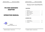
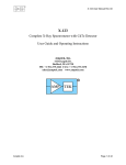
Refer to Figure 1 for an overview of the drive’s control board with relevant
ASD-NANOCOM interface sections indicated. The ASD comes from the
factory with a small jumper board (Toshiba part #55365A) installed in the
J4 connector. Remove this jumper board.
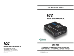
5.
Insert the ASD-NANOCOM interface into the drive control board’s J4/J5
connectors. Pay particular attention to the interface’s orientation, as
there is no keying to prevent it from inadvertently being installed
upside down. The header labeled “J4” on the back of the interface must
plug into the connector labeled “J4” on the drive’s control board, and
similarly the “J5” header must plug into the “J5” connector. When properly
mounted, the small 10-pin surface mount header on the top side of the
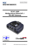
interface will be located in the lower left-hand corner. Refer to Figure 2 for
a detailed view of a correct installation. Confirm that the interface is fully
seated in the J4/J5 connectors.
6.
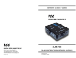
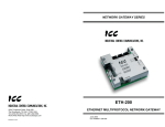
Place both duplex selection jumpers (refer to Figure 1) on the drive’s
control board in the “HALF” position. Refer to Figure 3 for a detailed view
of correctly-positioned duplex selection jumpers.
7
CN3
(RS-485 Network)
Duplex Selection
Jumpers
J4/J5 (Interface
Installation Area)
Figure 1: Pre-Installation Overview
Figure 2: Post-Installation Detail View
8
Figure 3: Network Terminal Block (CN3) and Duplex Selection Jumpers
7.
Connect the RS-485 network cable to the 4-position pluggable terminal
block on the drive’s control board labeled CN3 (refer to Figure 1 and Figure
3.) Refer to section 3 of this manual for detailed network connection
information. Ensure that the terminal block is fully seated into the terminal
block header, and route the network cable such that it is located well away
from any drive input power or motor wiring. Also take care to route the
cable away from any sharp edges or positions where it may be pinched.
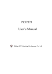
8.
Take a moment to verify that the ASD-NANOCOM interface is fully seated
in the drive control board’s J4/J5 connectors, that the duplex selection
jumpers are both in the “HALF” position, that the network cables are
properly terminated in CN3, that CN3 is fully seated in its header, and that
the RS-485 network cable has sufficient clearance from the drive’s input
power and output motor wiring. Refer to Figure 4.
9.
Reinstall the drive’s front cover / close the drive’s cabinet door.
10. Turn the power source to the drive ON, and verify that the drive functions
properly. If the drive does not appear to power up, or does not function
properly, immediately turn power OFF. Repeat steps 1 and 2 to remove
all power from the drive. Then, verify all connections. Contact ICC or
your local Toshiba representative for assistance if the problem persists.
9
Figure 4: Post-Installation Overview
10
3. RS-485 Connections
Figure 5 indicates the specific network connections to the RS-485 pluggable
terminal block (CN3). In general, there is no universal standardized labeling
scheme for RS-485 signal connections, so other equipment on your network
may use labels such as “+” and “-“ or “S1” and “S2”, etc. In such instances, the
correct connection scheme is usually intuitive (e.g. in FLN installations,
connection “+” to “A” and “-“ to “B”), or typically can be obtained via trial and
error by simply swapping the signal wires if no connection can be achieved.
Note that the “Shield” terminal has no internal connection: its purpose is simply
to provide a network cable shield chaining location between devices. The
shield is then typically connected to ground at one location only.
A
B
Signal Ground
Shield
Figure 5: RS-485 Terminal Block (CN3) Connections
11
4. Environmental Specifications
Item
Specification
Operating Environment
Indoors, less than 1000m above sea level, do not
expose to direct sunlight or corrosive / explosive
gasses
Operating Temperature
-10 ∼ +50°C (+14 ∼ +122°F)
Storage Temperature
-40 ∼ +85°C (-40 ∼ +185°F)
Relative Humidity
20% ∼ 90% (without condensation)
Vibration
2
5.9m/s {0.6G} or less (10 ∼ 55Hz)
Cooling Method
Self-cooled
12
5. Maintenance and Inspection
Preventive maintenance and inspection is required to maintain the interface in
its optimal condition, and to ensure a long operational lifetime. Depending on
usage and operating conditions, perform a periodic inspection once every three
to six months. Before starting inspections, always turn off all power supplies to
the drive, and wait at least five minutes after the drive’s “CHARGE” lamp has
gone out.
Inspection Points
•
Verify that the interface is fully seated in the drive control board’s J4/J5
connectors.
•
Confirm that the RS-485 network cable is still properly terminated in CN3.
Re-terminate if necessary.
•
Check that there are no defects in any attached wire terminal crimp points.
Visually check that the crimp points are not scarred by overheating.
•
Check that the CN3 pluggable terminal block is fully seated in its header.
Reseat if necessary.
•
Visually check all wiring and cables for damage. Replace as necessary.
•
Clean off any accumulated dust and dirt.
Please pay close attention to all periodic inspection points and maintain a good
operating environment.
13
6. Storage and Warranty
6.1 Storage
Observe the following points when the interface is not used immediately after
purchase or when it is not used for an extended period of time.
•
Avoid storing the unit in places that are hot or humid, or that contain large
quantities of dust or metallic dust. Store the unit in a well-ventilated
location.
•
When not using the unit for an extended period of time, apply power at
least once every two years and confirm that it still functions properly.
6.2 Warranty
The interface is covered under warranty by ICC, Inc. for a period of 12 months
from the date of installation, but not to exceed 18 months from the date of
shipment from the factory. For further warranty or service information, please
contact Industrial Control Communications, Inc. or your local distributor.
14
7. Network Configuration Parameters
Because the ASD-NANOCOM interface supports several different protocols,
some amount of configuration must be performed prior to inclusion on the
chosen network. This configuration is performed by setting certain drive
parameters, some of which dictate the characteristics of the network
communication, and some of which serve to facilitate the transfer of data
between the drive’s control board and the interface itself.
Throughout this section, take special note that the values of the
communication-related parameters are only validated upon drive powerup initialization. Therefore, if any of these parameters are changed, be sure
to cycle the drive’s incoming power to validate the changes.
Also note that the exact location of the indicated drive parameters may be
different among the various drive families. For example, on the Q7 drive family
most of these parameters are located in the Program…Comm Settings
group.
7.1 Primary Parameter Settings
The primary parameters are used by the ASD-NANOCOM interface to
configure itself on the RS-485 network. These parameters are as follows:
ASD
Ext
Ext
Ext
Ext
Ext
Ext
Ext
Ext
Number
Comm Cfg
Comm Cfg
Comm Cfg
Comm Cfg
Comm Cfg
Comm Cfg
Comm Cfg
Comm Cfg
#1
#2
#3
#4
#5
#6
#7
#8
These parameters are used as follows:
ASD Number or Inverter Number: Sets the drive’s station number on the
network. Although this parameter is adjustable from 0-255, not every value is a
valid entry. Refer to the protocol-specific sections of this manual (sections 8
through 10) for details pertaining to the allowable station number assignment
range for each supported protocol.
Ext Comm Cfg #1: Selects the RS-485 protocol. Allowable values are:
Modbus RTU ........... 0
Metasys N2.............. 1
Siemens FLN ........... 2
15
All other values will result in an INVALID PROTOCOL error indication (refer to
Ext Comm Cfg #4).
Ext Comm Cfg #2: Selects the Modbus RTU network characteristics (baud
rate, parity and stop bits). Refer to section 8 for more information.
Ext Comm Cfg #3: Defines an optional network timeout timer. Allowable
values are as follows:
0 ............. timer disabled
1-255 ..... 1s-255s timer selected
If the network timer is disabled, then no special processing will occur based on
the interval between received network packets: the interface will simply
continue to wait for the next incoming packet that it may take action on.
Upon initial power-up and after each timeout occurrence, the network timer will
not start until a complete packet has been received by the interface and
responded to. Once started, a complete packet must be received within the
timeout time setting to prevent the timer from expiring. As the timeout timer is
principally intended to monitor network health, received packets do not need to
be directed at any specific interface: even if an interface detects a packet
intended for a different interface on the network, it will consider the network
“healthy” and therefore reset its timeout timer.
The resultant behavior when a network timeout occurs is protocol-dependent.
Refer to the sections of this manual pertaining to the specific protocols for
further details.
Ext Comm Cfg #4: This parameter is a read-only error code. If the ASDNANOCOM interface experiences any fatal errors during initial configuration or
operation, then this parameter can be inspected to determine the specific error
code to aid in troubleshooting the problem. An example of a fatal error would
be if the Modbus RTU protocol is selected but the ASD Number parameter is
set to 0. A list of possible error codes is provided in Table 1.
Table 1: ASD-NANOCOM Error Codes
Error Code
Meaning
0
1
2
3
4
5
NO ERROR (normal operation)
INVALID EQUIPMENT
INVALID PROTOCOL
INVALID ADDRESS
INVALID NETWORK SETTINGS
RESOURCE ALLOCATION ERROR
16
Ext Comm Cfg #5 ∼ Ext Comm Cfg #8: These four parameters designate
user-selectable drive parameter numbers for special processing. Their use is
different for each protocol, so refer to the protocol-specific sections of this
manual for further details.
7.2 Additional Parameter Settings
Although the drive parameters outlined in section 7.1 provide the majority of the
RS-485 network configuration, there are several other communication-related
parameters that must be set appropriately to ensure reliable communication
between the drive and the ASD-NANOCOM interface itself. Verify that the
following drive communication-related parameters are set as indicated:
RS485 Baud Rate............. Although any setting will work properly, it is
recommended to set this value to 38400. This
setting will provide the maximum bandwidth
utilization between the drive and the ASDNANOCOM interface.
RS485 Timeout Time........ Set to 0s.
RS485 Response Time..... Set to 0.00s.
RS485 Master Output ....... Set to “Normal” or “No Slave”.
7.3 Controlling the Drive from the Network
If drive control (frequency command input, RUN/STOP, etc.) is to be performed
via the RS-485 network, then the following ASD parameters must also be set as
shown:
Command Mode ............... set to ”Use RS232/485”
Frequency Mode............... set to ”Use RS232/485”
As an alternative to setting the Command Mode and Frequency Mode selection
parameters, the override (priority) bits may be activated in the RS-485
command word (parameter FA04) instead. The specific method of activating
these bits depends on the protocol being used. For more information on the
proper use of the override bits, refer to the appropriate Toshiba documentation
regarding the drive’s command mode and frequency mode control hierarchy.
17
8. Modbus RTU Details
8.1 Node Addressing
ASD parameter ASD Number or Inverter number (depending on the drive
family) selects the Modbus node address. Valid addresses are 1 – 247. NOTE
that the factory default value for this parameter is 0, and must therefore be
changed to a valid Modbus node address, or an INVALID ADDRESS error
indication will result.
8.2 Network Characteristics
ASD parameter Ext Comm Cfg #2 selects the Modbus RTU network
characteristics (baud rate, parity and stop bits). Refer to Table 2 to determine
the association between this parameter’s value and the resultant network
characteristics.
Table 2: Modbus Network Configuration
Parameter Value
Baud Rate
Parity
Stop Bits
0
1
2
3
4
5
6
7
8
9
10
11
12
13
14
15
16
17
18
19
2400
2400
2400
4800
4800
4800
9600
9600
9600
19200
19200
19200
38400
38400
38400
2400
4800
9600
19200
38400
Odd
Even
None
Odd
Even
None
Odd
Even
None
Odd
Even
None
Odd
Even
None
None
None
None
None
None
1
1
1
1
1
1
1
1
1
1
1
1
1
1
1
2
2
2
2
2
Any other value for Ext Comm Cfg #2 will result in an INVALID NETWORK
SETTINGS error indication.
18
Note that the Modbus network characteristics indicated in Table 2 are unrelated
to the ASD parameters RS485 Baud Rate and Parity. The RS485 Baud
Rate and Parity parameters affect only the communication between the
drive’s control board CPU and the ASD-NANOCOM interface.
8.3 Supported Functions
The interface can act as a Modbus RTU slave according to the Modicon
Modbus Protocol Reference Guide (PI-MBUS-300 Rev. J). Supported Modbus
functions are indicated in Table 3. Broadcasts (address field=0) for functions 5,
6, 15 and 16 are supported.
Table 3: Supported Modbus Functions
Function Code
1
3
5
6
15
16
Function
Read coils
Read multiple registers
Write coil
Write single register
Force multiple coils
Write multiple registers
8.4 Register Addressing
To access a drive parameter, simply access the corresponding Modbus holding
register. Note that all Toshiba documentation lists drive registers in
hexadecimal (hex) format, so conversion to decimal may be required. For
example, let’s say we would like to access the drive’s “maximum frequency”
parameter. “Maximum frequency” is drive parameter 0011 (which is equivalent
to 0x0011 or 001116), so converting this to decimal results in a value of 1710.
Therefore, accessing Modbus holding register 17 (“known as” 40017) will
access the “maximum frequency” parameter.
8.5 Register Remapping
The ASD-NANOCOM interface allows access to holding register indexes from
110 - 6553510. This directly provides access to all ASD parameters from 000116
– FFFF16. For example, the drive’s RS-485 frequency command is located at
parameter FA05 (6400510). However, some Modbus master devices are
capable of indexing only a maximum of 9999 holding registers (110 - 999910 or
000116 – 270F16). Directly accessing holding register 64005 in order to set a
19
drive frequency command would therefore not be possible from these master
devices. To solve this problem and allow integration with all Modbus masters,
the ASD-NANOCOM interface implements “register remapping”.
Inspection of the Toshiba serial communications manual reveals that the drive’s
parameters are divided into two distinct regions within the full 0x0000 ~ 0xFFFF
ASD register map: the “lower address” range covers from 0x0000 to 0x09FF,
and the “upper address” range covers from 0xFA00 to 0xFFFF (not all values
within those ranges access valid ASD registers, of course). While all of the
parameters residing in the “lower address” range are directly accessible by
“register limited” masters, none of the parameters residing in the “upper
address” range are. Via register remapping, the ASD-NANOCOM interface
automatically maps all “upper address” ASD parameters into the contiguous
region immediately following the “lower address” range. To take advantage of
this feature, simply drop the initial “F” on any parameter index in the “upper
address” range and the resultant Modbus register request will automatically
access the correct internal ASD parameter.
For example, if we again wish to write a frequency command to the drive
(register FA05), we would change the FA0516 to 0A0516 and then convert this
index to decimal to obtain the resultant Modbus register (256510). Therefore,
writing to holding register 2565 will issue a new frequency command to the
drive. Of course, it is also possible to access the “upper address” parameters
at their original locations, so the RS-485 frequency command will be accessed
the same whether writing to holding register 256510 or 6400510.
8.6 Coil Mappings
The ASD-NANOCOM interface provides read/write support for Modbus coils.
Accessing coils does not reference any new physical data: coils are simply
indexes into various bits of Modbus holding registers. What this means is that
when a coil is accessed, that coil is resolved by the interface into a specific
holding register, and a specific bit within that holding register. The pattern of
coil-to-register/bit relationships can be described as follows:
Coils 1...16 map to holding register #1, bit0...bit15 (bit0=LSB, bit15=MSB)
Coils 17...32 map to holding register #2, bit0...bit15, and so on.
Arithmetically, the coil-to-register/bit relationship can be described as follows:
For any given coil, the holding register in which that coil resides can be
determined by:
coil + 15
holding register =
16
…Equation 1
Where the bracket symbols “ ” indicate the “floor” function, which means that
any fractional result (or “remainder”) is to be discarded, with only the integer
value being retained.
20
Also, for any given coil, the targeted bit in the holding register in which that coil
resides can be determined by:
bit = (coil − 1) % 16
…Equation 2
Where “coil” ∈[1…65535], “bit” ∈[0…15], and “%” is the modulus operator,
which means that any fractional result (or “remainder”) is to be retained, with
the integer value being discarded (i.e. it is the opposite of the “floor” function).
From these equations, it can be seen that the largest holding register number
that can be accessed via this coil-to-register mapping method is 4096 (which
contains coil 65535).
For clarity, let’s use Equation 1 and Equation 2 in a calculation example. Say,
for instance, that we are going to write to coil #41019. Using Equation 1, we
can determine that coil #41019 resides in holding register #2564, as 2564.625
= 2564. Then, using Equation 2, we can determine that the bit within holding
register #2564 that coil #41019 targets is (41019-1)%16 = 10, as 41018%16 =
mod(2563 r10) = 10. Therefore, writing to coil #41019 will write to holding
register #2564, bit #10.
As a side note to this example, if we convert holding register #2564 to its
hexadecimal equivalent, we obtain 0A0416. Applying our knowledge of register
remapping discussed in section 8.5, we know that this holding register
accesses ASD parameter FA04, which is the drive’s RS485 command word.
Bit #10 of this command word is the “run/stop” bit, and writing to coil #41019,
therefore, will allow us to command the drive to run and stop.
8.7 Data Mirroring
By using a technique called “data mirroring”, certain drive parameters are
handled by the interface with special processing that allows network accesses
to these parameters to have priority handling. This priority handling minimizes
the access latency incurred when reading a parameter from or writing a
parameter to the drive by maintaining copies of the parameter values within the
interface itself. By default, the following ASD parameters are always mirrored:
FA04 (RS-485 command word)
FA05 (RS-485 frequency command)
FD00 (output frequency)
FE01 (status 1)
In addition to the above parameters, up to 4 additional drive parameters can be
designated by the user to be mirrored. This can be beneficial by improving
network response time when an application regularly accesses parameters
other than the four mirrored parameters indicated above.
21
To designate a drive parameter as mirrored, simply enter its Modbus holding
register number into Ext Comm Cfg #5 ∼ Ext Comm Cfg #8. The factory
default values of parameters Ext Comm Cfg #5 ∼ Ext Comm Cfg #8 are 0,
which means “not designated”. As an example, let’s say that our application
requires that we constantly be monitoring ASD parameters “output voltage”
(FE05) and “status 2” (FE41). To mirror these parameters, we would first
convert their parameter numbers to decimal to determine the holding register
numbers (FE0516 = 6502910 and FE4116 = 6508910), and then enter these
decimal numbers into two of the Ext Comm Cfg parameters. In this case, we
can enter a value of 65029 into parameter Ext Comm Cfg #5 and a value of
65089 into Ext Comm Cfg #6. Upon completing this (and cycling power to
the drive), ASD parameters FE05 and FE41 will now be mirrored. This means
that network accesses to Modbus holding registers 65029 and 65089 (and 3589
and 3649 by virtue of register remapping as detailed in section 8.5) will now be
faster than if these registers were not being mirrored.
There are several issues to note regarding data mirroring:
•
ASD parameters that are being mirrored do not have any data
checking processing available. Therefore, a Modbus “success
response” will be returned to the network master even if the written
data value was invalid (out of range, for example). Therefore, use
caution with values written to command-type registers that are being
mirrored. In all cases, a mirrored register will return its current value
when read, so a write confirmation can be performed by reading a
command register after a write, and confirming that the read value
equals the previously-written value.
•
When entering “upper address” range parameter numbers (i.e.
parameters with indexes of FA00 - FFFF) into Ext Comm Cfg #5 ∼
Ext Comm Cfg #8, either the “actual” (Fxxx) or remapped (0xxx)
parameter number may be entered with equal results. Using our
previous example of mirroring ASD parameters FE05 and FE41 as a
demonstration of this, we could have entered either 65029 or 3589
into Ext Comm Cfg #5, and either 65089 or 3649 into Ext Comm
Cfg #6 and obtained the same results (“output voltage” and “status 2”
would be mirrored).
•
Ext Comm Cfg #5 ∼ Ext Comm Cfg #8 do not need to be used in
any particular order. For example, if only one user-defined parameter
was to be mirrored, its parameter number could be entered into any of
the Ext Comm Cfg #5 ∼ #8 parameters with equal results.
•
Recall from the discussion regarding parameter Ext Comm Cfg #3
in section 7.1 that if a timeout time is selected and a timeout event
occurs, then all user-selectable mirrored command registers (i.e. those
registers that affect drive control or configuration) will be automatically
written with a “failsafe” value of 0. Refer to section 8.8 for more
information.
22
•
The use of user-selectable mirroring is entirely optional, and therefore
is not required for proper network and drive operation, nor does it
affect Modbus mapping or addressing in any way. It is simply an
added feature that may help improve network efficiency in some
applications.
8.8 Timeout Behavior
If a timeout time is selected via Ext Comm Cfg #3, then after the designated
period of network inactivity the RS-485 frequency command (ASD parameter
FA04), RS-485 command word (ASD parameter FA05), and all user-selectable
mirrored command registers (Ext Comm Cfg #5 ∼ Ext Comm Cfg #8) will
be automatically written with a “failsafe” value of 0.
23
9. Metasys N2 Details
9.1 Node Addressing
ASD parameter ASD Number or Inverter number (depending on the drive
family) selects the Metasys N2 node address. Valid addresses are 1 – 255.
NOTE that the factory default value for this parameter is 0, and must therefore
be changed to a valid N2 node address, or an INVALID ADDRESS error
indication will result.
9.2 Network Characteristics
No configuration is necessary. The network characteristics are predetermined
according to the Metasys N2 specification.
9.3 Object Summaries
The interface contains a predefined set of analog and binary I/O points used for
configuring, controlling and monitoring the drive. The interface supports analog
input, analog output, binary input and binary output object types.
•
Analog input (AI) objects are used for monitoring analog status items. AI
objects support low alarm limits, low warning limits, high warning limits,
high alarm limits and differential values. Change of state (COS), alarm and
warning functions can also be enabled. An AI object will accept an
override command, but will not change its actual value or indicate override
active. Most AI objects are statically defined, but two are available for
user-configuration to access any available drive parameter.
•
Analog output (AO) objects are used for setting and monitoring analog
control and configuration items. An AO value can be modified by issuing
an override command. Issuing a release command will not cause the AO
to automatically return to its pre-override value, nor will the AO
automatically return to its pre-override value after a certain time period of
no communication. Most AO objects are statically defined, but two are
available for user-configuration to access any available drive parameter.
•
Binary input (BI) objects are used for monitoring discrete (digital) status
items. BI objects support COS, alarm enabling and normal/alarm status
indications. A BI object will accept an override command, but will not
change its actual value or indicate override active. All BI objects are
statically defined.
•
Binary output (BO) points are used for setting and monitoring discrete
control and configuration items. A BO value can be modified by issuing an
24
override command. Issuing a release command will not cause the BO to
automatically return to its pre-override value, nor will the BO return to its
pre-override value after a certain time period of no communication. All BO
objects are statically defined.
The Metasys device type for the gateway is VND.
9.4 Timeout Behavior
If a timeout time is selected via Ext Comm Cfg #3, then after the designated
period of network inactivity the frequency command (AO #1) and ASD
command word-related objects (AO #2 and BO #1 ∼ BO #7) will be
automatically written with a “failsafe” value of 0.
25
9.5 Supported Objects
Table 4 provides a listing of the Metasys objects supported by the interface.
Table 4: Supported Objects
NPA2
Units
AI
AI
AI
AI
AI
AI
AI
AI
AI
AI
1
2
3
4
5
6
7
8
9
10
Hz
%
%
kW
kWh
%
%
----
BI
1
--
Run / stop status
BI
2
--
Forward / reverse status
BI
3
--
Fault status
BI
4
--
“F” programmable input terminal status
BI
5
--
“R” programmable input terminal status
BI
6
--
“ST” programmable input terminal status
BI
7
--
“RES” programmable input terminal status
BI
8
--
“S1” programmable input terminal status
BI
9
--
“S2” programmable input terminal status
BI
10
--
“S3” programmable input terminal status
BI
11
--
“S4” programmable input terminal status
BI
12
--
“OUT1” programmable output terminal status
BI
13
--
“OUT2” programmable output terminal status
BI
14
--
“FL” programmable output terminal status
AO
AO
AO
AO
1
2
3
4
Hz
----
Frequency command
Preset speed selection
Ext Comm Cfg #7 reference
Ext Comm Cfg #8 reference
BO
1
--
Run / stop command
BO
2
--
Forward / reverse selection
BO
3
--
Emergency off command
NPT
1
Description
Output frequency
Load current
Output voltage
Input power
System energy
RR analog input
VI / II analog input
Fault code
Ext Comm Cfg #5 reference
Ext Comm Cfg #6 reference
26
Range/Value
0.00 ∼ 400.00
0.00 ∼ 327.67
0.00 ∼ 327.67
0.00 ∼ 655.35
0.00 ∼ 42.9x10⁶
0.00 ∼ 100.00
0.00 ∼ 100.00
0 ∼ 255
0 ∼ 65535
0 ∼ 65535
0 = stopped
1 = running
0 = forward
1 = reverse
0 = not faulted
1 = faulted
0 = OFF
1 = ON
0 = OFF
1 = ON
0 = OFF
1 = ON
0 = OFF
1 = ON
0 = OFF
1 = ON
0 = OFF
1 = ON
0 = OFF
1 = ON
0 = OFF
1 = ON
0 = OFF
1 = ON
0 = OFF
1 = ON
0 = OFF
1 = ON
0.00 ∼ 400.00
0 ∼ 15
0 ∼ 65535
0 ∼ 65535
0 = stop
1 = run
0 = forward
1 = reverse
0 = no action
1 = emerg. off
NPT1
NPA2
Units
Description
BO
4
--
Fault reset command
BO
5
--
Feedback enable/disable selection
BO
6
--
Frequency priority
BO
7
--
Command priority
BO
8
--
Output terminal Data Out 1
BO
9
--
Output terminal Data Out 2
BO
10
--
Output terminal Data Out 3
NOTE 1...... NPT = Network Point Type
NOTE 2...... NPA = Network Point Address
27
Range/Value
0 = no action
1 = reset
0 = enable
1 = disable
0 = OFF
1 = ON
0 = OFF
1 = ON
0 = OFF
1 = ON
0 = OFF
1 = ON
0 = OFF
1 = ON
9.6 Object Details
This section gives a brief overview of each object, including any notable
behavior or settings. Further information may be obtained by referring to the
appropriate drive operation manual and 7-Series Serial Communications User
Manual. While most of the available objects are predefined, two analog input
and two analog output objects are available that can be user-configured to
access any available drive parameters. This allows a customized application to
be easily developed.
9.6.1 Analog Input Objects
AI #1..... Output frequency in Hz. ASD parameter FD00.
AI #2..... Load current in % (100% = drive’s rated current). ASD parameter
FE03.
AI #3..... Output voltage in % (100% = drive’s rated voltage). ASD parameter
FE05.
AI #4..... Input power consumption (drive + motor) in kW. ASD parameter
FE29.
AI #5..... System energy consumption (drive + motor) in kWh. ASD parameter
FE69.
AI #6..... Indicates the signal level currently being applied to the ASD’s RR
analog input terminal. This can be used to monitor such items as
feedback sensor outputs and other process variables. Expressed in %
(100% = input rated value). ASD parameter FE35.
AI #7..... Similar to AI #6, this object indicates the signal level currently being
applied to the ASD’s VI/II analog input terminal. ASD parameter
FE36.
AI #8..... Indicates the present fault code. Under normal operation (no faults),
this value will be 0. ASD parameter FC90.
AI #9..... In addition to the predefined analog input objects (AI #1 ∼ AI #8), two
user-defined AI objects are available (AI #9 and AI #10). To define
which ASD parameters are to be associated with these AI’s, enter
their parameter numbers (in decimal) into parameters Ext Comm Cfg
#5 and Ext Comm Cfg #6. Parameter Ext Comm Cfg #5
corresponds to AI #9 and Ext Comm Cfg #6 corresponds to AI #10.
For example, if the drive’s peak current (ASD parameter FE31) is to
be monitored in AI #9, then convert the parameter number to decimal
(0xFE31 = 6507310) and enter the result (65073) into Ext Comm Cfg
#5. After cycling power, AI #9 will then provide access to peak
current. Note that because any available ASD parameter can be
accessed via this method, AI #9 and AI #10 are dimensionless and
28
have multiplier values of 1 (i.e. the object’s data will be the raw value
as maintained internally to the drive).
The factory default values of parameters Ext Comm Cfg #5 and
Ext Comm Cfg #6 are 0, which means “not designated”. When
these drive parameters are “not designated”, their corresponding AI
object values will always be 0.
AI #10 ...Refer to the explanation for AI #9 above. The data accessed via this
object is defined by the decimal ASD parameter value entered into
Ext Comm Cfg #6.
9.6.2 Binary Input Objects
BI #1 .....Indicates whether the drive is running or stopped. ASD parameter
FE01, bit #10.
BI #2 .....Indicates whether the drive is running in the forward or reverse
direction. ASD parameter FE01, bit #9.
BI #3 .....Indicates whether or not the drive is currently faulted.
BI #4 .....Indicates the status of the “F” programmable input terminal. ASD
parameter FE06, bit #0.
BI #5 .....Indicates the status of the “R” programmable input terminal. ASD
parameter FE06, bit #1.
BI #6 .....Indicates the status of the “ST” programmable input terminal. ASD
parameter FE06, bit #2.
BI #7 .....Indicates the status of the “RES” programmable input terminal. ASD
parameter FE06, bit #3.
BI #8 .....Indicates the status of the “S1” programmable input terminal. ASD
parameter FE06, bit #4.
BI #9 .....Indicates the status of the “S2” programmable input terminal. ASD
parameter FE06, bit #5.
BI #10 ...Indicates the status of the “S3” programmable input terminal. ASD
parameter FE06, bit #6.
BI #11 ...Indicates the status of the “S4” programmable input terminal. ASD
parameter FE06, bit #7.
BI #12 ...Indicates the status of the “OUT1” programmable output terminal.
ASD parameter FE07, bit #0.
BI #13 ...Indicates the status of the “OUT2” programmable output terminal.
ASD parameter FE07, bit #1.
BI #14 ...Indicates the status of the “FL” programmable output terminal. ASD
parameter FE07, bit #2.
29
9.6.3 Analog Output Objects
AO #1 ... Sets the drive’s RS-485 frequency command. Note that the drive will
only use this value as its active frequency command if the Frequency
Mode parameter is set to ”Use RS232/485”, or if the “frequency
override” bit (BO #6) is ON. Although the adjustment range for this
object is 0.00Hz ∼ 400.00Hz, the actual frequency command will be
internally limited by the Upper Limit Frequency and Lower
Limit Frequency parameters. ASD parameter FA05.
AO #2 ... Preset speed selection. A value of “0” means “no preset speed
selected”, while values of 1 ∼ 15 correspond to preset speeds #1 ∼
#15. To run a selected preset speed, the drive must be configured to
be using RS-485 commands (parameter Command Mode set to ”Use
RS232/485” or BO #7 ON) and a RUN command must be active (BO
#1). ASD parameter FA04, bits #0 ∼ #3.
AO #3 ... In addition to the predefined analog output objects (AO #1 and AO
#2), two user-defined AO objects are available (AO #3 and AO #4).
To define which ASD parameters are to be associated with these
AO’s, enter their parameter numbers (in decimal) into parameters Ext
Comm Cfg #7 and Ext Comm Cfg #8. Parameter Ext Comm Cfg
#7 corresponds to AO #3 and Ext Comm Cfg #8 corresponds to AO
#4.
For example, if the drive’s deceleration time #1 (ASD parameter 0010)
is to be set via AO #3, then convert the parameter number to decimal
(0x0010 = 1610) and enter the result (16) into Ext Comm Cfg #7.
After cycling power, AO #3 will then provide access to deceleration
time #1. Note that because any available ASD parameter can be
accessed via this method, AO #3 and AO #4 are dimensionless and
have multiplier values of 1 (i.e. the object’s data will be the raw value
as maintained internally to the drive).
The factory default values of parameters Ext Comm Cfg #7 and
Ext Comm Cfg #8 are 0, which means “not designated”. When
these drive parameters are “not designated”, their corresponding AO
object values will always be 0, and they will not access any drive
parameters.
AO #4 ... Refer to the explanation for AO #3 above. The data accessed via this
object is defined by the decimal ASD parameter value entered into
Ext Comm Cfg #8.
9.6.4 Binary Output Objects
Note that the drive will only use the commands indicated in BO #1, BO #2 and
BO #5 if the Command Mode parameter is set to ”Use RS232/485”, or if the
“command override” bit (BO #7) is ON.
30
BO #1 .....Run/stop command. ASD parameter FA04, bit #10.
BO #2 .....Forward/reverse command. ASD parameter FA04, bit #9.
BO #3 .....Forces the drive to fault “Emergency Off”. ASD parameter FA04, bit
#12.
BO #4 .....Resets the drive when it is faulted. ASD parameter FA04, bit #13.
BO #5 .....Enables or disables process (PID) feedback control. Note that this
object does not activate (turn on) feedback control; it only enables or
disables feedback control once it has already been activated. ASD
parameter FA04, bit #5.
BO #6 .....RS-485 frequency priority selection. Allows the frequency command
from the RS-485 network to be used by the drive without having to
set the Frequency Mode parameter. Refer to the Toshiba
documentation regarding “Command Mode and Frequency Mode
Control” for detailed information pertaining to the frequency source
hierarchy and the use of overrides. ASD parameter FA04, bit #14.
BO #7 .....RS-485 command priority selection. Allows commands (BO #1, BO
#2, BO #5 and AO #2) from the RS-485 network to be used by the
drive without having to explicitly set the Command Mode parameter.
Refer to the Toshiba documentation regarding “Command Mode and
Frequency Mode Control” for detailed information pertaining to the
command source hierarchy and the use of overrides. ASD
parameter FA04, bit #15.
BO #8 .....Output terminal Data Out 1. Any programmable output terminals
that are configured to output Data Out 1 (NO) or Data Out 1
(NC) will follow the value (or the inverted value) of this BO. ASD
parameter FA50, bit #0.
BO #9 .....Output terminal Data Out 2. Any programmable output terminals
that are configured to output Data Out 2 (NO) or Data Out 2
(NC) will follow the value (or the inverted value) of this BO. ASD
parameter FA50, bit #1.
BO #10 ...Output terminal Data Out 3. Any programmable output terminals
that are configured to output Data Out 3 (NO) or Data Out 3
(NC) will follow the value (or the inverted value) of this BO. ASD
parameter FA50, bit #2.
31
10. Siemens FLN Details
The Siemens FLN protocol is only applicable to the Q7 drive family.
10.1 Node Addressing
ASD parameter ASD Number selects the FLN node address. Valid addresses
are 0 – 98. NOTE that the factory default value for ASD Number is 0.
10.2 Network Characteristics
No configuration is necessary. The network characteristics are predetermined
according to the FLN specification.
10.3 Timeout Behavior
If a timeout time is selected via Ext Comm Cfg #3, then after the designated
period of network inactivity frequency command (#28) and ASD command
word-related objects (#30 and #33 ∼ #39) will be automatically written with a
“failsafe” value of 0.
32
10.4 Supported Subpoints
The interface contains a predefined set of FLN subpoints used for configuring,
controlling and monitoring the drive (refer to Table 5).
Table 5: Supported Subpoints
Point #
Point
Type
Subpoint
Name
Factory
Default
Units
Slope
Intercept
On
Text
Off
Text
01
LAO
ADDRESS
99
–
1
0
–
–
02
LAO
APPLICATION
2736
–
1
0
–
–
03
LAI
OUTPUT FREQ
0
HZ
0.01
0
–
–
04
LAI
LOAD CURRENT
0
PCT
0.01
0
–
–
05
LAI
OUTPUT VOLT
0
PCT
0.01
0
–
–
06
LAI
INPUT POWER
0
KW
0.01
0
–
–
07
LAI
KWH
0
KWH
0.01
0
–
–
08
LAI
RR INPUT
0
PCT
0.01
0
–
–
09
LAI
VI.II INPUT
0
PCT
0.01
0
–
–
10
LAI
FAULT CODE
0
–
1
0
–
–
11
LAI
COMM CFG 5
0
–
1
0
–
–
12
LAI
COMM CFG 6
0
–
1
0
–
–
13
LDI
RUN.STOP
0
–
1
0
RUN
STOP
14
LDI
FWD.REV
0
–
1
0
REV
FWD
15
LDI
FAULT STATUS
0
–
1
0
FAULT
NORM
16
LDI
F TERMINAL
0
–
1
0
ON
OFF
17
LDI
R TERMINAL
0
–
1
0
ON
OFF
18
LDI
ST TERMINAL
0
–
1
0
ON
OFF
19
LDI
RES TERMINAL
0
–
1
0
ON
OFF
20
LAO
OVRD TIME
1
HRS
1
0
–
–
21
LDI
S1 TERMINAL
OFF
–
1
0
ON
OFF
22
LDI
S2 TERMINAL
OFF
–
1
0
ON
OFF
23
LDI
S3 TERMINAL
OFF
–
1
0
ON
OFF
24
LDI
S4 TERMINAL
OFF
–
1
0
ON
OFF
25
LDI
OUT1
OFF
–
1
0
ON
OFF
26
LDI
OUT2
OFF
–
1
0
ON
OFF
27
LDI
FL
OFF
–
1
0
ON
OFF
28
LAO
FREQ CMD
0
HZ
0.01
0
–
–
33
Point #
Point
Type
Subpoint
Name
Factory
Default
Units
Slope
Intercept
On
Text
Off
Text
29
LDO
DAY.NGT
DAY
–
1
0
NIGHT
DAY
30
LAO
PRESET SPEED
0
–
1
0
–
–
31
LAO
COMM CFG 7
0
–
1
0
–
–
32
LAO
COMM CFG 8
0
–
1
0
–
–
33
LDO
RUN.STOP CMD
STOP
–
1
0
RUN
STOP
34
LDO
FWD.REV CMD
FWD
–
1
0
REV
FWD
35
LDO
EMER. OFF
OFF
–
1
0
ON
OFF
36
LDO
FAULT RESET
OFF
–
1
0
ON
OFF
37
LDO
PID ENABLE
ON
–
1
0
OFF
ON
38
LDO
FREQ PRIO
OFF
–
1
0
ON
OFF
39
LDO
CMD PRIO
OFF
–
1
0
ON
OFF
40
LDO
DATA OUT 1
OFF
–
1
0
ON
OFF
41
LDO
DATA OUT 2
OFF
–
1
0
ON
OFF
42
LDO
DATA OUT 3
OFF
–
1
0
ON
OFF
99
LAO
ERROR STATUS
0
–
1
0
–
–
Notes:
•
Points not listed are not used in this application.
•
All points have the same value for English units and SI units.
34
10.5 Subpoint Details
This section gives a brief overview of each subpoint, including any notable
behavior or settings. Further information may be obtained by referring to the
Toshiba Q7 Series Operation Manual and 7-Series Serial Communications
User Manual. While most of the available objects are predefined, two LAI and
two LDO subpoints are available that can be user-configured to access any
available drive parameters. This allows a customized application to be easily
developed.
10.5.1 LAI Subpoints
#3..........Output frequency in Hz. ASD parameter FD00.
#4..........Load current in % (100% = drive’s rated current). ASD parameter
FE03.
#5..........Output voltage in % (100% = drive’s rated voltage). ASD parameter
FE05.
#6..........Input power consumption (drive + motor) in kW. ASD parameter
FE29.
#7..........System energy consumption (drive + motor) in kWh. ASD parameter
FE69.
#8..........Indicates the signal level currently being applied to the ASD’s RR
analog input terminal. This can be used to monitor such items as
feedback sensor outputs and other process variables. Expressed in %
(100% = input rated value). ASD parameter FE35.
#9..........Similar to #8, this object indicates the signal level currently being
applied to the ASD’s VI/II analog input terminal. ASD parameter
FE36.
#10........Indicates the present fault code. Under normal operation (no faults),
this value will be 0. ASD parameter FC90.
#11........In addition to the predefined LAI subpoints (#3 ∼ #10), two userdefined LAI subpoint are available (#11 and #12). To define which
ASD parameters are to be associated with these LAI’s, enter their
parameter numbers (in decimal) into parameters Ext Comm Cfg #5
and Ext Comm Cfg #6. Parameter Ext Comm Cfg #5
corresponds to #11 and Ext Comm Cfg #6 corresponds to #12.
For example, if the drive’s peak current (ASD parameter FE31) is to
be monitored in #11, then convert the parameter number to decimal
(0xFE31 = 6507310) and enter the result (65073) into Ext Comm Cfg
#5. After cycling power, subpoint #11 will then provide access to peak
current. Note that because any available ASD parameter can be
accessed via this method, subpoints #11 and #12 are dimensionless
35
and have multiplier values of 1 (i.e. the object’s data will be the raw
value as maintained internally to the drive).
The factory default values of parameters Ext Comm Cfg #5 and
Ext Comm Cfg #6 are 0, which means “not designated”. When
these drive parameters are “not designated”, their corresponding
subpoint values will always be 0.
#12 ....... Refer to the explanation for #11 above. The data accessed via this
object is defined by the decimal ASD parameter value entered into
Ext Comm Cfg #6.
10.5.2 LDI Subpoints
#13 ....... Indicates whether the drive is running or stopped. ASD parameter
FE01, bit #10.
#14 ....... Indicates whether the drive is running in the forward or reverse
direction. ASD parameter FE01, bit #9.
#15 ....... Indicates whether or not the drive is currently faulted.
#16 ....... Indicates the status of the “F” programmable input terminal. ASD
parameter FE06, bit #0.
#17 ....... Indicates the status of the “R” programmable input terminal. ASD
parameter FE06, bit #1.
#18 ....... Indicates the status of the “ST” programmable input terminal. ASD
parameter FE06, bit #2.
#19 ....... Indicates the status of the “RES” programmable input terminal. ASD
parameter FE06, bit #3.
#21 ....... Indicates the status of the “S1” programmable input terminal. ASD
parameter FE06, bit #4.
#22 ....... Indicates the status of the “S2” programmable input terminal. ASD
parameter FE06, bit #5.
#23 ....... Indicates the status of the “S3” programmable input terminal. ASD
parameter FE06, bit #6.
#24 ....... Indicates the status of the “S4” programmable input terminal. ASD
parameter FE06, bit #7.
#25 ....... Indicates the status of the “OUT1” programmable output terminal.
ASD parameter FE07, bit #0.
#26 ....... Indicates the status of the “OUT2” programmable output terminal.
ASD parameter FE07, bit #1.
#27 ....... Indicates the status of the “FL” programmable output terminal. ASD
parameter FE07, bit #2.
36
10.5.3 LAO Subpoints
#28........Sets the drive’s RS-485 frequency command. Note that the drive will
only use this value as its active frequency command if the Frequency
Mode parameter in Program…Utility Group is set to ”Use
RS232/485”, or if the “frequency override” bit (#38) is ON. Although
the adjustment range for this object is 0.00Hz ∼ 400.00Hz, the actual
frequency command will be internally limited by the Upper Limit
Frequency and Lower Limit Frequency parameters. ASD
parameter FA05.
#30........Preset speed selection. A value of “0” means “no preset speed
selected”, while values of 1 ∼ 15 correspond to preset speeds #1 ∼
#15. To run a selected preset speed, the drive must be configured to
be using RS-485 commands (parameter Command Mode set to
”RS232/485” or #39 ON) and a RUN command must be active (#33).
ASD parameter FA04, bits #0 ∼ #3.
#31........In addition to the predefined LAO subpoints (#28 and #30), two userdefined LAO subpoints are available (#31 and #32). To define which
ASD parameters are to be associated with these LAO’s, enter their
parameter numbers (in decimal) into parameters Ext Comm Cfg #7
and Ext Comm Cfg #8. Parameter Ext Comm Cfg #7
corresponds to #31 and Ext Comm Cfg #8 corresponds to #32.
For example, if the drive’s deceleration time #1 (ASD parameter 0010)
is to be set via #31, then convert the parameter number to decimal
(0x0010 = 1610) and enter the result (16) into Ext Comm Cfg #7.
After cycling power, #31 will then provide access to deceleration time
#1. Note that because any available ASD parameter can be accessed
via this method, #31 and #32 are dimensionless and have multiplier
values of 1 (i.e. the object’s data will be the raw value as maintained
internally to the drive).
The factory default values of parameters Ext Comm Cfg #7 and
Ext Comm Cfg #8 are 0, which means “not designated”. When
these drive parameters are “not designated”, their corresponding
subpoint values will always be 0, and they will not access any drive
parameters.
#32........Refer to the explanation for #31 above. The data accessed via this
object is defined by the decimal ASD parameter value entered into
Ext Comm Cfg #8.
10.5.4 LDO Subpoints
Note that the drive will only use the commands indicated in subpoints #33, #34
and #37 if the Command Mode parameter in Program…Utility Group is set
to ”RS232/485”, or if the “command override” bit (#39) is ON.
37
#33 ......... Run/stop command. ASD parameter FA04, bit #10.
#34 ......... Forward/reverse command. ASD parameter FA04, bit #9.
#35 ......... Forces the drive to fault “Emergency Off”. ASD parameter FA04, bit
#12.
#36 ......... Resets the drive when it is faulted. ASD parameter FA04, bit #13.
#37 ......... Enables or disables process (PID) feedback control. Note that this
object does not activate (turn on) feedback control; it only enables or
disables feedback control once it has already been activated. ASD
parameter FA04, bit #5.
#38 ......... RS-485 frequency priority selection. Allows the frequency command
from the RS-485 network to be used by the drive without having to
set the Frequency Mode parameter. Refer to the Toshiba
documentation regarding “Command Mode and Frequency Mode
Control” for detailed information pertaining to the frequency source
hierarchy and the use of overrides. ASD parameter FA04, bit #14.
#39 ......... RS-485 command priority selection. Allows commands (#30, #33,
#34, and #37) from the RS-485 network to be used by the drive
without having to explicitly set the Command Mode parameter. Refer
to the Toshiba documentation regarding “Command Mode and
Frequency Mode Control” for detailed information pertaining to the
command source hierarchy and the use of overrides. ASD
parameter FA04, bit #15.
#40 ......... Output terminal Data Out 1. Any programmable output terminals
that are configured to output Data Out 1 (NO) or Data Out 1
(NC) will follow the value (or the inverted value) of this BO. ASD
parameter FA50, bit #0.
#41 ......... Output terminal Data Out 2. Any programmable output terminals
that are configured to output Data Out 2 (NO) or Data Out 2
(NC) will follow the value (or the inverted value) of this BO. ASD
parameter FA50, bit #1.
#42 ......... Output terminal Data Out 3. Any programmable output terminals
that are configured to output Data Out 3 (NO) or Data Out 3
(NC) will follow the value (or the inverted value) of this BO. ASD
parameter FA50, bit #2.
38
11. Notes
39
40
ASD INTERFACE SERIES
ICC
INDUSTRIAL CONTROL COMMUNICATIONS, INC.
ICC
INDUSTRIAL CONTROL COMMUNICATIONS, INC.
Madison Office
1600 Aspen Commons, Suite 210
Middleton, WI USA 53562-4720
Tel: [608] 831-1255 Fax: [608] 831-2045
http://www.iccdesigns.com
ASD-NANOCOM
Houston Office
2204 Timberloch Place, Suite 250
The Woodlands, TX USA 77380-1049
Tel: [281] 292-0555 Fax: [281] 292-0564
Printed in U.S.A
MULTIPROTOCOL COMMUNICATIONS INTERFACE
FOR TOSHIBA 7-SERIES ADJUSTABLE SPEED DRIVES
March 2006
ICC #10572-2.100-000