1
ASD INTERFACE SERIES
ICC
INDUSTRIAL CONTROL COMMUNICATIONS, INC.
ICC
INDUSTRIAL CONTROL COMMUNI
COMMUNICATIONS,
CATIONS, INC.
2204 Timberloch Place, Suite 250
The Woodlands, TX USA 77380-1049
Tel: [281] 292-0555 Fax: [281] 292-0564
http://www.iccdesigns.com
Printed in U.S.A
ETH-100
ETHERNET COMMUNICATIONS INTERFACE
FOR TOSHIBA ADJUSTABLE SPEED DRIVES
February 2004
ICC #10449-2.100-000
Introduction
Thank you for purchasing the ICC, Inc. ETH-100 Ethernet Communications
Interface for the Toshiba 7-Series, 9-Series and VF-nC1 Series Adjustable
Speed Drives. Before using the ETH-100 interface, please familiarize yourself
with the product and be sure to thoroughly read the instructions and
precautions contained in this manual. In addition, please make sure that this
instruction manual is delivered to the end user of the drive units with which the
ETH-100 interface is connected, and keep this instruction manual in a safe
place for future reference or drive/interface inspection.
This instruction manual describes the device specifications, wiring methods,
maintenance procedures, supported functions and usage methods for the
ETH-100 Ethernet communications interface.
In conjunction with this manual, the following manuals are supplied by Toshiba,
and are essential both for ensuring a safe, reliable system installation as well
as for realizing the full potential of the ETH-100 interface:
•
•
•
•
•
•
Toshiba TOSVERT VF-S7 Series Instruction Manual
Toshiba TOSVERT VF-S9 Series Instruction Manual
Toshiba TOSVERT VF-A7 Series Instruction Manual
Toshiba TOSVERT VF-nC1 Series Instruction Manual
Toshiba G7 Series Operation Manual
Toshiba VF-S7 Industrial Inverter Serial Communications Option Manual
If you do not have copies available of the documents relevant to your
installation, please contact Toshiba or your local Toshiba distributor to obtain
them, or copies may be downloaded from http://www.tic.toshiba.com (subject
to availability).
Before continuing, please take a moment to ensure that you have received all
materials shipped with your kit. These items are:
•
•
•
ETH-100 interface in DIN rail mountable case
2 meter DB9-RJ45 MMI port cable (part number 10425)
This manual
1
ETH-100 Ethernet Interface User's Manual
Part Number 10449-2.100-000
Printed in U.S.A.
©2001-2004 Industrial Control Communications, Inc.
All rights reserved
Industrial Control Communications, Inc. reserves the right to make changes
and improvements to its products without providing notice.
Notice to Users
INDUSTRIAL CONTROL COMMUNICATIONS, INC.’S PRODUCTS ARE NOT
AUTHORIZED FOR USE AS CRITICAL COMPONENTS IN LIFE-SUPPORT
DEVICES OR SYSTEMS. Life-support devices or systems are devices or
systems intended to sustain life, and whose failure to perform, when properly
used in accordance with instructions for use provided in the labeling and user's
manual, can be reasonably expected to result in significant injury.
No complex software or hardware system is perfect. Bugs may always be
present in a system of any size. In order to prevent danger to life or property, it
is the responsibility of the system designer to incorporate redundant protective
mechanisms appropriate to the risk involved.
2
Usage Precautions
Operating Environment
•
Please use the ETH-100 only when the ambient temperature of the
environment into which the unit is installed is within the following
specified temperature limits:
Operation: -10 ∼ +50°C (+14 ∼ +122°F)
Storage:
-40 ∼ +85°C (-40 ∼ +185°F)
•
Avoid installation locations that may be subjected to large shocks or
vibrations.
Avoid installation locations that may be subjected to rapid changes in
temperature or humidity.
•
Installation and Wiring
•
•
Proper ground connections are vital for both safety and signal
reliability reasons. Ensure that all electrical equipment is properly
grounded.
Route all communication cables separate from high-voltage or noiseemitting cabling (such as ASD input/output power wiring).
ASD Connections
•
•
•
•
•
•
Do not touch charged parts of the drive such as the terminal block
while the drive’s CHARGE lamp is lit. A charge will still be present in
the drive’s internal electrolytic capacitors, and therefore touching these
areas may result in an electrical shock. Always turn all drive input
power supplies OFF, and wait at least 5 minutes after the CHARGE
lamp has gone out before connecting communication cables.
To avoid misoperation, do not connect any ETH-100 terminals to either
the ASD’s E/GND terminals, the motor, or to any other power ground.
When making common serial connections between the ETH-100 and
ASDs, do not use cables that exceed 5 meters in length.
For further drive-specific precaution, safety and installation
information, please refer to the appropriate documentation supplied
with your drive.
Internal drive EEPROMs have a limited life span of write cycles.
Observe all precautions contained in this manual and your ASD
manual regarding which drive registers safely may and may not be
repetitively written to.
Because the ETH-100 derives its control power from the connected
drives, removing power to all connected drives will also cause the
ETH-100 to lose power.
3
TABLE OF CONTENTS
1.
The Point Database Concept ......................................................6
2.
Mechanical Diagrams ..................................................................7
2.1
2.2
2.3
Enclosure ..............................................................................................7
Mounting Clip ........................................................................................8
External Interface ..................................................................................9
3.
Feature Summary.......................................................................10
4.
Installing the Interface...............................................................13
4.1
4.2
Installation for G7 ASDs......................................................................13
Installation for S7, S9, A7 and VF-nC1 ASDs .....................................15
5.
Grounding ..................................................................................17
6.
Environmental Specifications ..................................................18
7.
Maintenance and Inspection ....................................................19
8.
Storage and Warranty ...............................................................20
8.1
8.2
9.
Storage ...............................................................................................20
Warranty .............................................................................................20
LED Indicators ...........................................................................21
9.1
9.2
9.3
Module and Ethernet Indicators ..........................................................21
ASD Port Indicators ............................................................................21
MMI Port Indicators .............................................................................22
10.
Internal Battery...........................................................................23
11.
Initial Configuration...................................................................24
11.1
11.2
12.
ARP Method........................................................................................24
Console Method ..................................................................................25
Console Access .........................................................................26
12.1
RS232 .................................................................................................26
12.1.1
Requirements .............................................................................26
12.1.2
Connection .................................................................................26
12.1.3
Application Configuration ...........................................................26
12.2
Telnet ..................................................................................................29
12.2.1
Requirements .............................................................................29
12.2.2
Connection .................................................................................29
4
12.2.3
Application Configuration........................................................... 29
12.3
Command Overview ........................................................................... 30
13.
Modbus TCP/IP...........................................................................34
13.1
Drive Channel Access ........................................................................ 34
13.2
Timeout Processing............................................................................ 34
13.3
Supported Modbus Functions............................................................. 35
13.4
Modbus/Drive Register Mappings ...................................................... 35
13.4.1
Point Mapping............................................................................ 35
13.4.2
Direct (Implicit) Mapping ............................................................ 36
13.4.3
Universal Access Registers ....................................................... 37
13.5
Coil Mappings..................................................................................... 38
13.6
Exceptions and Troubleshooting ........................................................ 40
13.6.1
Common Error Causes .............................................................. 40
13.6.2
General ASD Access Notes....................................................... 41
14.
14.1
14.2
14.3
14.4
14.5
14.6
14.7
14.8
14.9
14.10
14.11
14.12
14.13
15.
Embedded Web Server..............................................................42
Authentication..................................................................................... 43
Communication Status Indicators....................................................... 44
Unit Status .......................................................................................... 44
Set Date and Time.............................................................................. 44
Network Configuration ........................................................................ 44
Master Timeout Configuration ............................................................ 45
Authentication Configuration .............................................................. 46
Parent Selection ................................................................................. 46
Child Selection ................................................................................... 46
Child Edit........................................................................................ 47
Radix Selection .............................................................................. 48
Error Code Reference .................................................................... 49
Allocated Sockets Report............................................................... 49
Firmware Updates......................................................................50
15.1
Requirements ..................................................................................... 50
15.2
Connection ......................................................................................... 50
15.3
Using the RFU Utility .......................................................................... 51
15.3.1
Required Files............................................................................ 51
15.3.2
First-Time Configuration ............................................................ 51
15.3.3
Transmitting Firmware Files ...................................................... 53
15.4
Wrap-Up ............................................................................................. 54
16.
Notes ...........................................................................................55
5
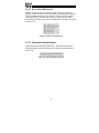
1. The Point Database Concept
The heart of the ETH-100’s mapping capabilities is an element called the
“point database” (refer to Figure 1). The point database is entirely userconfigurable, and provides the end-to-end mapping information that allows
primary (Ethernet) network requests to be routed to the correct locations on the
secondary network (the ASD ports), while at the same time ensuring that the
content of the request will be understood once it gets there. Additionally, the
point database provides the added benefit of “data mirroring”, whereby current
copies of point values (ASD registers) are maintained locally within the ETH100 itself. This greatly reduces the primary network’s request-to-response
latency time, as requests (read or write) can be entirely serviced locally,
thereby eliminating the time required to execute a secondary network
transaction.
When properly configured, the gateway will become essentially “transparent”
on the network, and the primary network master can engage in a seamless
dialogue with one or more secondary network devices (ASDs).
Ethernet
Network
Point
Database
Figure 1: The Point Database Concept
6
ASD
Ports
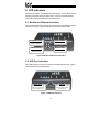
2. Mechanical Diagrams
2.1 Enclosure
Figure 2: Enclosure Dimensions (units are inches)
7
2.2 Mounting Clip
Figure 3: Mounting Clip Dimensions (units are inches)
8
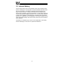
2.3 External Interface
Ethernet
Network
Configuration
Switches
Chassis
Ground
Figure 4: Bottom View
MMI Port
Channel A
Channel B
Figure 5: Front View
9
Channel C
3. Feature Summary
Primary Network
IEEE 802.3 10BaseT Ethernet compliant. Shielded RJ45 connector accepts
standard CAT5-type 8-conductor unshielded twisted-pair (UTP) patch cables.
Secondary Network
ASD common serial: The ETH-100 provides support for simultaneous
connection of three Toshiba 7-series, 9-series or VF-nC1 ASDs via the drives’
common serial (aka logic level) communication ports. ASD connections use
the same standard RJ45 style 8-conductor UTP patch cables: any standard
CAT5 Ethernet cable (found in most electronics stores) 5 meters or less in
length can be used to connect the ETH-100 to the drives.
Power Supply
Self-contained. Powered directly from the connected drives. Drives can be
connected to the ETH-100 on any channel (A, B or C) in any order or
combination. When more than 1 drive is connected to the unit, the ETH-100
will draw its control power from the drive with the highest power supply voltage.
Supported Protocols
•
Primary Network
o Schneider Electric Modbus TCP/IP, release 1.0.
Conformance Class 0 and partial Class 1 and Class 2
compliant. Allows up to 8 simultaneous Modbus TCP/IP
client connections.
•
Secondary Network
o Toshiba ASD (common serial)
Text-Based Console Configuration
Basic unit configuration is performed via a text-based console interface,
available locally over RS232 by using the included MMI cable and a standard
PC terminal program such as Microsoft Windows HyperTerminal®, or over
Ethernet via a Telnet session. The unit also provides initial configuration
access via ICMP (“ping”) configuration.
Macromedia® Flash-Enabled Embedded Web Server
Advanced unit configuration and drive monitoring/control are also provided via
an embedded web server using the HTTP protocol. The ETH-100’s web server
feature provides direct data access and control via standard web browsers
such as Microsoft Internet Explorer and Netscape Navigator. The latest
version of Macromedia Flash Player browser plug-in is required.
Point File-Based Configuration
A point file (primary / secondary network mapping definition file) is stored in the
unit’s internal battery-backed file system. Point files can also be uploaded
10
from / downloaded to a PC, which provides the capability for PC-based file
backup and easy configuration copying to multiple units. Sample point files
and related documentation can also be downloaded from the ICC web site,
uploaded to a unit, and custom-modified to suit a specific application.
Drive AutoScan Algorithm
ASD common serial port connections are automatically established and
continuously monitored (when points are defined for that drive). No drive
configuration needs to be performed to connect the ETH-100 to the drives.
Just plug it in – it’s that simple.
Modbus TCP/IP Universal Access Registers
Modbus TCP/IP holding registers 9998 and 9999 provide an easy method of
directly accessing any drive register that may have already been “masked” by
definition of an internal point. Refer to section 13.4.3 for more information.
Per-Point Failsafe Timeout Processing
A “master” IP address and timeout time can be assigned to the unit. Each
point defined in the point database also has the capability to be assigned an
optional failsafe timeout value. When an unexpected socket failure from the
“master” device occurs, all points with timeout processing enabled will be
written with their failsafe values. This provides an additional level of process
security in the event of a network or master device disturbance.
Selectable Grounding
Switch SW1 #2 allows the ground plane to be split into 2 different sections:
one for the main control circuitry and another for the Ethernet network
connector shield and associated magnetics. The latter ground point is
accessible for external termination via the GND screw terminal located on the
bottom of the unit. Refer to section 5 for more information related to
grounding.
Indicators
•
•
•
•
•
1 green “LNK” LED that is on whenever a valid Ethernet connection is
detected.
1 red “ACT” LED that flashes whenever data is transferred across the
Ethernet network.
1 bicolor red/green “MS” LED that indicates module status information.
1 bicolor red/green “NS” LED that indicates network status information.
2 green LEDs on each of the drive communication connectors and on the
MMI port connector.
Refer to section 9 for more detailed information about the LED indicators and
their meanings.
11
MMI Port Connector
RS232-level. Use the DB9-to-RJ45 MMI cable supplied with the ETH-100 kit to
interface with the unit for either console-based configuration, point file
upload/download, or flash firmware downloading.
Field-Upgradeable
As new firmware becomes available, the ETH-100 unit can be upgraded in the
field by the end-user. Refer to section 15 for more information.
Versatile 3-Way DIN-Rail Mounting System
The unit’s enclosure is provided with a mounting clip attached to the rear of the
unit. This clip allows the unit to be mounted 3 different ways:
•
For DIN rail mounting, snap the mounting clip onto a standard DIN
rail, and then snap the unit enclosure onto the clip’s retaining tabs.
This allows easy removal or repositioning of the unit on the DIN rail
during wiring.
•
For panel mounting, the mounting clip can be bolted directly to a flat
panel via the two bolt holes at the top and bottom of the clip. Refer to
section 2.2 for mounting clip mechanical details. Once the mounting
clip is securely attached to the panel, the unit enclosure can be
snapped onto the clip’s retaining tabs.
•
For fixed DIN rail mounting, a combination of the above two
techniques can be employed. First, snap the mounting clip onto a
DIN rail and position it in its desired location. Then, the mounting clip
can be bolted to the DIN rail support panel, securing it in place.
Lastly, the unit can be snapped onto the fixed mounting clip.
In all cases, the unit can be easily unsnapped from the mounting clip to
temporarily provide easier access to the configuration switches, chassis
ground terminal or network connector.
12
4. Installing the Interface
The ETH-100 connects to each drive via the drive’s common serial (logic level)
communication port, typically located on either the main drive control board
(G7), on the front of the drive enclosure under a small snap-on cover (A7, S9),
on the right-hand side of the drive enclosure under a small snap-on cover (S7),
or on the bottom side of the drive enclosure (VF-nC1). Although in general no
drive parameters need to be configured in order to use the gateway, it is
advantageous to check that the drive’s common serial communication data
rate is set to its maximum speed. Because the ETH-100 will communicate to
each drive only at the drive’s configured data rate, this will provide the fastest
response time for drive-to-network data transfers. For information on checking
the drive’s common serial communication data rate, refer to the appropriate
manual supplied with your drive.
Note that the common serial communication parameters of each drive are
handled independently by the ETH-100, which means that different drive
families may be connected to different channels of the unit in any combination,
and that the drives connected to each channel may simultaneously
communicate to the unit at completely different baud rates, parity settings, etc.
Drives can be connected to any ETH-100 channel in any order or combination.
When more than one drive is connected to the unit, the gateway will draw its
control power from the source with the highest power supply voltage.
Installation of the ETH-100 should only be performed by a qualified technician
familiar with the maintenance and operation of the connected drives. To install
the ETH-100, complete the steps outlined in the following sections related to
your specific drive.
4.1 Installation for G7 ASDs
1.
2.
3.
CAUTION! Verify that all input power sources to the drives to
be connected have been turned OFF and are locked and tagged out.
DANGER!
Wait at least 5 minutes for the drive’s
electrolytic capacitors to discharge before proceeding to the next step. Do
not touch any internal parts with power applied to the drive, or for at
least 5 minutes after power to the drive has been removed. A hazard
exists temporarily for electrical shock even if the source power has
been removed. Verify that the CHARGE LED has gone out before
continuing the installation process.
Attach the mounting clip and interface enclosure in your desired manner
(refer to page 12 for more information).
13
4.
Remove the drive’s front cover / open the drive’s cabinet door (refer to the
appropriate drive manual for instructions how to do this).
5.
The drive’s LCD panel (also called the “Electronic Operator Interface” or
“EOI”) can communicate with the drive via either the RS485/RS232
channel (CNU1/CNU1A) or the common serial channel (CNU2/CNU2A).
Because the interface uses the common serial channel, the LCD panel
must be configured to use the RS485/RS232 channel. If the drive to be
connected is currently using CNU2 (on the drive control board) and
CNU2A (on the LCD panel), then this connection must first be switched
over to CNU1 (on the drive control board) and CNU1A (on the LCD panel).
Refer to Toshiba’s documentation for any precautions or notices regarding
this connection change. If the LCD panel is already connected via the
RS485/RS232 channel, then no change is required.
6.
Configure the drive’s LCD panel to communicate via the RS485/RS232
channel by setting parameter ”Communication Setting
Parameters...Communication Settings...Select LCD Port
Connection” to “RS485/232 serial”.
7.
Connect the drive’s common serial communication port (CNU2) to one of
the ASD channels of the interface with the communication cable
(communication cable is not included with the ETH-100 kit). When
choosing cables for this connection, standard 24 AWG category 5 (CAT5)
unshielded twisted-pair (UTP) 8-conductor cables found in Ethernet
networks in most office environments can be used. The maximum
allowable length for these cables is 5 meters. Although there are many
varieties and styles of CAT5 UTP cables available, ICC strongly
recommends using only high-quality cables from reputable manufacturers
to guarantee optimal noise immunity and cable longevity. Ensure that
each end of the cable is fully seated into the modular connectors, and
route the cable such that it is located well away from any drive input power
or motor wiring. Also take care to route the cable away from any sharp
edges or positions where it may be pinched.
8.
Reinstall the drive’s front cover / close the drive’s cabinet door.
9.
Repeat steps 1-8 to connect other drive(s) as needed.
10. Connect the Ethernet network cable to the shielded RJ45 connector
marked “Network” on the bottom of the unit. If a ground cable is going to
be used, attach the ground cable to the screw terminal marked “GND” on
the bottom side of the unit (refer to section 5). Ensure that the network
cable is fully seated into the modular connector, and route the cable such
that it is located well away from any drive input power or motor wiring.
Also take care to route the cable away from any sharp edges or positions
where it may be pinched.
11. Take a moment to verify that the interface and all primary and secondary
network cables have sufficient clearance from drives, motors, or powercarrying electrical wiring.
12. Turn the power sources to all connected drives ON, and verify that the
drives function properly. If the drives do not appear to power up, or do not
14
function properly, immediately turn power OFF. Repeat steps 1 and 2 to
remove all power from the drives. Then, verify all connections. Contact
ICC or your local Toshiba representative for assistance if the problem
persists.
4.2 Installation for S7, S9, A7 and VF-nC1 ASDs
1.
2.
CAUTION! Verify that all input power sources to the drives to
be connected have been turned OFF and are locked and tagged out.
DANGER!
Wait at least 5 minutes for the drive’s
electrolytic capacitors to discharge before proceeding to the next step. Do
not touch any internal parts with power applied to the drive, or for at
least 5 minutes after power to the drive has been removed. A hazard
exists temporarily for electrical shock even if the source power has
been removed. Verify that the CHARGE LED has gone out before
continuing the installation process.
3.
Attach the mounting clip and interface enclosure in your desired manner
(refer to page 12 for more information).
4.
Remove the drive’s common serial communication port cover if it has one
(refer to the appropriate drive manual for instructions how to do this). Do
not discard this cover, as it should be reinstalled to minimize
contamination of the port’s electrical contacts if the interface is ever
disconnected from the drive.
5.
Connect the drive’s common serial communication port to one of the ASD
channels of the interface with the communication cable (communication
cable is not included with the gateway kit). When choosing cables for this
connection, standard 24 AWG category 5 (CAT5) unshielded twisted-pair
(UTP) 8-conductor cables found in Ethernet networks in most office
environments can be used. The maximum allowable length for these
cables is 5 meters. Although there are many varieties and styles of CAT5
UTP cables available, ICC strongly recommends using only high-quality
cables from reputable manufacturers to guarantee optimal noise immunity
and cable longevity. Ensure that each end of the cable is fully seated into
the modular connectors, and route the cable such that it is located well
away from any drive input power or motor wiring. Also take care to route
the cable away from any sharp edges or positions where it may be
pinched.
6.
Repeat steps 1, 2, 4 and 5 to connect other drive(s) as needed.
7.
Connect the Ethernet network cable to the shielded RJ45 connector
marked “Network” on the bottom of the unit. If a ground cable is going to
be used, attach the ground cable to the screw terminal marked “GND” on
the bottom side of the unit (refer to section 5). Ensure that the network
15
cable is fully seated into the modular connector, and route the cable such
that it is located well away from any drive input power or motor wiring.
Also take care to route the cable away from any sharp edges or positions
where it may be pinched.
8.
Take a moment to verify that the interface and all primary and secondary
network cables have sufficient clearance from drives, motors, or powercarrying electrical wiring.
9.
Turn the power sources to all connected drives ON, and verify that the
drives function properly. If the drives do not appear to power up, or do not
function properly, immediately turn power OFF. Repeat steps 1 and 2 to
remove all power from the drives. Then, verify all connections. Contact
ICC or your local Toshiba representative for assistance if the problem
persists.
16
5. Grounding
Grounding is of particular importance for reliable, stable operation.
Communication system characteristics may vary from system to system,
depending on the system environment and grounding method used. The ETH100 interface is provided with a “GND” screw terminal on the bottom of the
unit. This “GND” terminal constitutes an effective “chassis ground”, and is
directly connected to the metallic housing of the shielded RJ45 Ethernet
network connector and to the appropriate locations on its integrated isolation
magnetics.
This chassis ground plane is physically separate from the ETH-100’s control
logic ground plane, which is directly referenced to the CC (control common)
terminal on the connected drives. Switch SW1 #2 on the ETH-100 unit,
however, provides a method to selectively connect these 2 ground planes
together.
When switch SW1 #2 is ON (switch in the “down” position when looking at the
bottom of the ETH-100 unit end-on), the ETH-100’s control logic ground plane
and chassis ground plane are connected together. In this configuration, no
external GND wire should be connected to the unit’s GND terminal. In this
case, the chassis ground plane is directly connected to the drives’ CC
reference, and Toshiba typically recommends that the CC reference of the
drives not be connected to earth ground. Refer to your drive’s instruction
manual for specific information about the CC terminal and ground connections.
In some high-noise environments or under unusual wiring conditions, it may be
possible to obtain improved Ethernet communication characteristics by
referencing the ETH-100’s “chassis ground” to a localized earth ground. In
these cases, place switch SW1 #2 in the OFF (up) position and connect the
GND screw terminal to an appropriate ground connection.
Please be sure to consider the following general points for making proper
ground connections:
Grounding method checkpoints
1. Make all ground connections such that no ground current flows through
the case or heatsink of a connected drive.
2. Do not connect the ETH-100’s GND terminal to a power ground or any
other potential noise-producing ground connection (such as a drive’s “E”
terminal).
3. Do not make connections to unstable grounds (paint-coated screw heads,
grounds that are subjected to inductive noise, etc.)
17
6. Environmental Specifications
Item
Specification
Operating Environment
Indoors, less than 1000m above sea level, do not
expose to direct sunlight or corrosive / explosive
gasses
Operating Temperature
-10 ∼ +50°C (+14 ∼ +122°F)
Storage Temperature
-40 ∼ +85°C (-40 ∼ +185°F)
Relative Humidity
20% ∼ 90% (without condensation)
Vibration
5.9m/s {0.6G} or less (10 ∼ 55Hz)
Grounding
Cooling Method
2
Selectable split ground planes
Self-cooled
18
7. Maintenance and Inspection
Preventive maintenance and inspection is required to maintain the interface in
its optimal condition, and to ensure a long operational lifetime. Depending on
usage and operating conditions, perform a periodic inspection once every
three to six months. Before starting inspections, always turn off all power
supplies to connected drives, and wait at least five minutes after each drive’s
“CHARGE” lamp has gone out.
Inspection Points
•
Check that the dust covers for all unused RJ45 ports are seated firmly in
their connectors.
•
Check that the ASD communication cables are fully seated in both the
drive and interface RJ45 ports. Reseat if necessary.
•
Check that there are no defects in any attached wire terminal crimp points.
Visually check that the crimp points are not scarred by overheating.
•
Visually check all wiring and cables for damage. Replace as necessary.
•
Clean off any accumulated dust and dirt.
•
If use of the interface is discontinued for extended periods of time, apply
power at least once every two years and confirm that the unit still functions
properly.
•
Do not perform hi-pot tests on the interface, as they may damage the unit.
Please pay close attention to all periodic inspection points and maintain a good
operating environment.
19
8. Storage and Warranty
8.1 Storage
Observe the following points when the interface is not used immediately after
purchase or when it is not used for an extended period of time.
•
Avoid storing the unit in places that are hot or humid, or that contain large
quantities of dust or metallic dust. Store the unit in a well-ventilated
location.
•
When not using the unit for an extended period of time, apply power at
least once every two years and confirm that it still functions properly.
8.2 Warranty
The interface is covered under warranty by ICC, Inc. for a period of 12 months
from the date of installation, but not to exceed 18 months from the date of
shipment from the factory. For further warranty or service information, please
contact Industrial Control Communications, Inc. or your local distributor.
20
9. LED Indicators
The interface contains several different LED indicators, each of which conveys
important information about the status of the unit and connected networks.
These LEDs and their functions are summarized here.
9.1 Module and Ethernet Indicators
The module and Ethernet indicators are located between the MMI port and the
Channel A drive port. Figure 6 indicates the functions of these LEDs.
ACT (Ethernet ACTivity)
NS (Network Status)
Flashes red when network
activity is detected
Currently reserved
LNK (Ethernet LiNK)
MS (Module Status)
Solid green when valid
network link exists
Currently reserved
Figure 6: Module and Ethernet Indicators
9.2 ASD Port Indicators
Each ASD port RJ45 connector contains two integrated green LEDs. Figure 7
indicates the functions of these LEDs.
Network Access
Drive Link
Blinks in 0.1s-long bursts
when drive is accessed by
primary network master
Solid green when a logical
connection exists with the
attached drive
Figure 7: ASD Port Indicators
21
The Network Access indicator is useful for confirming that a specific drive
channel is being accessed correctly by the primary network, while the Drive
Link indicator provides an easy method of determining that the interface and
drive are successfully exchanging data, independent of primary network
activity.
9.3 MMI Port Indicators
The MMI port RJ45 connector also contains two integrated green LEDs.
Figure 8 indicates the functions of these LEDs.
Active Sockets Indicator
Blinks in 0.25s-long bursts
separated by 2s of OFF time:
number of consecutive blinks
indicates number of open TCP/IP
sockets (client connections)
Reserved
Currently reserved
Figure 8: MMI Port Indicators
The Active Sockets indicator is helpful in determining how many TCP/IP
sockets are currently allocated to Ethernet clients (masters). As indicated in
Figure 8, the number of currently-allocated sockets can be determined by
counting the number of concurrent short blinks. Each stream of short blinks is
terminated by 2s of continuous off time, after which the next stream of short
blinks begins.
22
10. Internal Battery
The ETH-100 interface has an internal battery that is used to backup the file
system containing the unit configuration and point database information when
the unit is unpowered. This battery is designed to last the lifetime of the
product under normal use. However, if the interface is left unpowered for
several years, the battery may become exhausted. For this reason, always be
certain to download the configured point file to a PC via the Xmodem protocol
so that it will be available for uploading again if the battery fails and requires
replacement. Additionally, it is recommended to record the IP address, subnet
mask and gateway settings in the notes section (section 16) of this manual for
future reference.
The battery is a soldered-in type, and is not user-replaceable. If the battery
becomes discharged, contact ICC for replacement assistance.
23
11. Initial Configuration
The ETH-100 typically requires configuration prior to communicating on an
Ethernet network. This fundamental configuration is achieved via one of two
possible methods: using ICMP (“ping”) configuration via the Address
Resolution Protocol (ARP), or via a text-based console interface, accessible
over an RS232 serial channel and a telnet interface. The following are the
factory-set values of the most important Ethernet parameters:
IP Address.........................192.168.16.100
Subnet Mask .....................255.255.255.0
Default Gateway................192.168.16.2
If these parameters are not compatible with your network settings, they will
need to be modified.
11.1 ARP Method
The IP address can be changed remotely by using the Address Resolution
Protocol (ARP). This is performed by adding a static entry into a PC’s ARP
cache table, which stores the associations between a device’s IP and physical
(MAC) addresses. The unit is then “pinged” from a command prompt (MS
DOS™ window) to assign the new IP address to it. Below is an example of the
commands used to change the unit’s IP address:
arp -s <IP address> <MAC address>
ping <IP address>
arp -d <IP address>
The initial “arp –s” command adds a static association between the unit’s MAC
address and the desired IP address to the PC’s ARP table. When the ping
command is executed with the IP address as an argument, the PC sends this
information to the unit indicated by the associated MAC address. The unit then
detects that it was addressed with the correct MAC address and adopts the IP
address indicated in the ICMP “ping” packet. The optional “arp –d” command
then removes the static route from the PC’s ARP table.
The unit’s MAC address is printed on a label on the back of the case. An
example of setting a unit’s IP address to 192.168.16.110 would look like:
arp -s 192.168.16.110 00-90-C2-C0-29-8B
ping 192.168.16.110
arp –d 192.168.16.110
Forcing the unit to adopt the new IP address completes only half of the ARP
configuration process. In addition to the IP address being changed, the unit
also automatically configures its subnet mask to 255.255.255.255. This setting
essentially allows only the computer that issued the ping command to
communicate with the unit. From this computer, then, the user must also
access the unit’s web page via a web browser, or its console via a telnet
24
session, in order to assign a new subnet mask. Until the new subnet mask is
assigned to the unit, the IP address change is only temporary. If the unit loses
power or is otherwise reset prior to submitting a new subnet mask, the
previous IP address and subnet mask settings will return.
Note that if the subnet mask is to be modified via the unit’s web page, that
network elements such as HTTP proxy servers may relay the web page
request for the configuring computer. The unit, seeing the HTTP request from
a computer other than that which performed the initial “ping”, will ignore such a
request. Therefore, be sure to bypass or disable any proxy servers at least
temporarily when using this configuration method.
For security reasons, once the ARP method of configuration has been
successfully completed (i.e. a new subnet mask has been entered), the ARP
method of configuration will be disabled, and all future attempts at using this
method will be ignored by the unit. It is possible, however, to re-enable the
ARP method via a console command (refer to section 12.3).
11.2 Console Method
The console method of configuration is achieved via a text-based console
interface, accessible over an RS232 serial channel and a telnet interface. The
RS232 console is accessed by using the included DB9-RJ45 cable to connect
the ETH-100’s MMI port to a PC’s serial (COM) port, and then running a
terminal emulation program, such as Windows® HyperTerminal. If the ARP
method of initial configuration is not used, then the RS232 console must be
accessed. More information about the console interface and its commands
can be found in section 12.
25
12. Console Access
12.1 RS232
The console is accessible via an RS232 interface for direct connection to a
computer’s serial (COM) port. This is performed by using the included DB9RJ45 cable to connect the ETH-100’s MMI port to the computer’s serial port.
This will typically be the initial configuration channel, as the telnet interface can
only be accessed once the network parameters have already been established
and the device is communicating on the Ethernet network.
12.1.1 Requirements
All that is needed is a computer with a standard serial (COM) port containing
some sort of communications software (such as HyperTerminal, shipped with
Microsoft Windows operating systems) and the included MMI cable (ICC part
number #10425). Any communications software and PC will work, provided
they support ASCII communications at 38.4kbaud.
12.1.2 Connection
The ETH-100 ships from the factory with a dust cover installed in the MMI port.
To minimize contamination of the port’s electrical contacts, keep this dust
cover in place whenever the MMI port is not in use.
Connect the RJ45 end of the MMI cable to the MMI port, and connect the other
end to the computer’s serial port. Make sure that switch SW1 #1 is in the
“OFF” position.
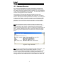
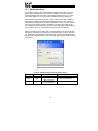
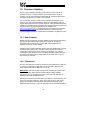
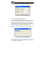
12.1.3 Application Configuration
As previously mentioned, any PC communication software and PC serial port
can be used. The software configuration example given here will be for
Windows HyperTerminal communicating via COM1.
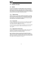
Figure 9 shows the “Connect To” tab of the properties window for COM1.
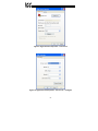
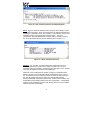
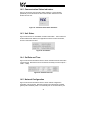
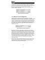
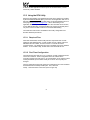
Figure 10 shows the window that appears when “Configure” is selected in the
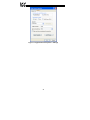
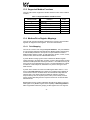
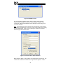
“Connect To” tab. Figure 11 shows the “Settings” tab of the properties window.
Most of these settings are their default values: usually the only change needed
is the “Bits per second” setting shown in Figure 10.
26
Figure 9: HyperTerminal Properties…Connect To
Figure 10: HyperTerminal Properties…Connect To…Configure
27
Figure 11: HyperTerminal Properties…Settings
28
12.2 Telnet
The console is also accessible via a Telnet interface for remote administration
over Ethernet once the unit is communicating on the network. The Telnet
console uses well-known port 23. Note that although only 1 telnet console
session can be active at any given time, the telnet console and RS232 console
operate independently and can be used simultaneously.
12.2.1 Requirements
All that is needed is a computer with telnet software that can access the ETH100 over the Ethernet network. Telnet software is typically included as a
standard component of Microsoft Windows and other PC operating systems.
12.2.2 Connection
No special connections are required, other than the PC running the Telnet
application must be able to access the ETH-100 to be configured.
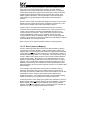
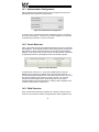
12.2.3 Application Configuration
Although any software vendor’s Telnet client application can be used, the
configuration example given here will use the Microsoft Windows Telnet
application. To start the Telnet application, simply type “telnet” at either a DOS
(command) prompt or in the “Start…Run” window. Once the telnet client
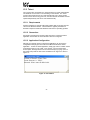
screen opens, the target device can be accessed simply by typing “open” at
the Telnet prompt with the ETH-100’s IP address as an argument. Refer to
Figure 12.
Figure 12: Telnet Menu
29
12.3 Command Overview
The console provides standard access and configuration methods for the
various network parameters and configurations supported by the ETH-100.
The number and type of supported console commands may vary with different
console version and application version firmware. This section will present an
overview of the supported console commands.
It is important to note that unless otherwise indicated, each of these
commands will become effective immediately after it has been successfully
entered. This may have several repercussions; for example, if you change the
IP address of the device via the Telnet console, then you will lose the telnet
connection to the device (as it was a connection to the old IP address) and
therefore must re-connect to the console if you wish to continue changing
parameters. Also note that the console commands are not case-sensitive.
Help: This command shows the console version and an overview of all
available commands. As indicated in the returned help information, typing
“Help <command>” with a specific command will return help information
specific to that command. Refer to Figure 13 for the help command output via
Telnet. All further display screens shown in this section will be from Telnet,
although they will look identical when accessed via the serial channel (MMI
port).
Figure 13: "Help" Command
Set: The “Set” command actually encompasses several subcommands, each
of which allows setting a different configuration parameter. To set a
parameter, two arguments are required: the parameter’s name and the value
to set it to. Figure 14 shows an example of changing the IP address of a
device to 192.168.16.120. After this command is entered, the device will then
reconfigure itself to allow network access via the IP address 192.168.16.120.
30
Figure 14: "Set" Command Overview and Implementation
Show: Figure 15 shows an example of this command, which displays current
configuration information. Some of this information (IP Address, Netmask and
Gateway) is configurable via the “set” command. The “Firmware Version” field
indicates the unit’s current application firmware version. The “Ping
Configuration” field indicates whether or not the ability to remotely configure
the unit via the ARP method is currently allowed (refer to section 11.1).
Figure 15: "Show" Command Overview
Xmodem: The “xmodem” command allows point configuration files to be
transferred between the unit and a PC. Refer to section 13.4.1 for more
information about point mapping. As Xmodem is a serial protocol, the xmodem
command only applies to the serial console (MMI port)
Whenever a point configuration is created, it is highly recommended that a
backup copy of the point configuration file be downloaded from the unit to a
PC. One reason for this is in case it becomes necessary to restore the file to
the unit’s file system later (such as if the unit’s internal backup battery
becomes exhausted and requires replacement). Another reason is that it may
be desirable to load multiple units with the same configuration. A downloaded
point file can be uploaded to any ETH-100, allowing the user to clone multiple
units with the same configuration.
31
Two different variations of the Xmodem protocol are supported (CRC and
Checksum) for those serial communication packages that only support one or
the other. However, some programs can automatically adapt to the user’s
selection, making the specific Xmodem protocol selection arbitrary. The first
argument of the xmodem command indicates the mode, and must be set to
either “/crc” for Xmodem CRC mode, or “/cs” for Xmodem checksum mode.
As mentioned above, point files can be downloaded and uploaded. The
second argument in the xmodem command indicates the action to take, and
must be set to either “/d” to download the point configuration file from the unit,
or “/u” to upload a point file configuration to the unit.
Figure 16 shows an example of initiating an Xmodem download in CRC mode.
Once the message “The ETH-100 is ready to send its point file via
Xmodem…Download the file now” appears, the user has 30 seconds to start
the Xmodem download. This can be performed in HyperTerminal by clicking
the “receive” button on the tool bar. Figure 17 shows the dialog box that will
appear after clicking the “receive” button. Specify the folder in which to place
the received file, select Xmodem as the receiving protocol, and click “Receive”.
One last dialog box will prompt the user to name the received file, and then the
transfer will begin.
Figure 16: “Xmodem” Command Overview and Implementation
32
Figure 17: HyperTerminal receive file dialog box
When uploading a file, the procedure is similar to downloading. Enter “/u”
instead of “/d” for the action parameter of the xmodem command. Once the
xmodem upload command is entered, the user will have 30 seconds to click
the “send” button on the tool bar in HyperTerminal and initiate the Xmodem
upload transaction. Upon successful completion of the Xmodem upload, the
unit will reset, and the uploaded point file will become the unit’s active point
configuration. The previous point configuration cannot be recovered.
Ping config reset: This command re-enables the ability to configure the unit’s
IP address via the ARP method (refer to section 11.1). For security reasons,
whenever the ARP method of configuration is successfully completed, the unit
disables this method, and subsequent attempts at ARP configuration will be
ignored. By entering the “ping config reset” console command, however, the
unit will once again allow the ARP method of configuration. Refer to Figure 18.
Recall that the current ARP method configuration status can always be
obtained via the “show” command.
Figure 18: "Ping Config Reset" Overview and Implementation
33
13. Modbus TCP/IP
The ETH-100 interface supports Schneider Electric’s Modbus TCP/IP protocol,
release 1.0. The ETH-100 is conformance class 0 and partial class 1 and
class 2 compliant, and allows up to 8 simultaneous Modbus TCP/IP client
connections (sockets).
13.1 Drive Channel Access
Each specific drive channel (Channel A, Channel B and Channel C) is
accessed via the “Unit Identifier” (UI) field of a Modbus TCP/IP packet. Drive
channel A is accessed when the UI field is set to “1”, channel B is accessed
when the UI field is set to “2”, and channel C is accessed when the UI field is
set to “3”. Any other UI setting is invalid and will result in a GATEWAY PATH
UNAVAILABLE exception (Modbus TCP/IP exception code 0A).
13.2 Timeout Processing
The unit supports two different socket timeout processing capabilities.
Standard socket timeouts are set to 30s, which means that if a particular open
socket experiences no activity for more than 30s, then the interface assumes
that the client or network has experienced some sort of unexpected problem,
and the ETH-100 will close that socket.
Alternatively, a “master” IP address and timeout time can be assigned to the
unit. Each point defined in the point database has the capability to be
assigned an optional failsafe timeout value. When an unexpected socket
failure from the “master” client occurs, all points with timeout processing
enabled will be written with their failsafe values. This provides an additional
level of process security in the event of a network or master device
disturbance.
34
13.3 Supported Modbus Functions
The ETH-100 interface supports the Modbus TCP/IP function codes indicated
in Table 1.
Table 1: Supported Modbus TCP/IP Functions
Function Code
1
3
5
6
15
16
Function
Read coils
Read multiple registers
Write coil
Write single register
Force multiple coils
Write multiple registers
Class
1
0
1
1
2
0
13.4 Modbus/Drive Register Mappings
The ETH-100 uses three methods to determine the manner in which Modbus
registers are mapped to ASD registers. These are outlined below.
13.4.1 Point Mapping
The unit can contain a user-configurable point database. The point database
is a list of register mappings that describe how Modbus holding registers map
to Toshiba ASD parameters. Each point in the point database contains a
Modbus holding register number, an ASD parameter number, a value, a name,
a timeout value, and a timeout enable/disable selection.
A point’s Modbus holding register number indicates the Modbus register
number the point is accessed with. Similarly, a point’s ASD parameter number
indicates the ASD parameter that the point refers to. Each ASD channel (A, B,
and C) has its own independent list of points. The point database can contain
a maximum of 100 total points, distributed in any manner among the three
ASD channels.
A point’s value contains the value of the ASD register that it refers to. Via a
service called data mirroring, point values are constantly being updated via
communication with the connected drives and maintained locally within the
interface itself. This greatly reduces the Ethernet network’s request-toresponse latency time, as requests (read or write) can be entirely serviced
locally, thereby eliminating the time required to execute an on-demand ASD
data transaction.
Besides data mirroring, another advantage afforded by the ability to map any
ASD register to any Modbus register is the capability of data reorganization.
Data reorganization allows the grouping of ASD registers into more logical or
35
efficient patterns to suit a given application. Because the Ethernet network
client never “sees” the true ASD register numbers, the point mapping
assignments can be determined by any user-defined criteria. For instance,
several disjoint ASD status registers can be assigned to contiguous Modbus
registers, thereby allowing the status items to be read with a single “read
multiple register” transaction. Data reorganization can therefore enhance
network efficiency by minimizing the total number of data transactions
required.
A point’s name is simply a descriptive title assigned to the point to more easily
identify the point’s function during device configuration and monitoring. This
name is only accessible via the HTTP (web browser) interface.
A point’s timeout value and timeout enable/disable selection are used in
conjunction with the master device timeout function. When a timeout from a
“master” client is detected, the timeout enable/disable selections for all
configured points are inspected. Those points that are found to have their
timeout enable/disable selections set to “enabled” will then have their
configured timeout values automatically written to their corresponding ASD
registers. This mechanism provides for a flexible set of ASD failsafe conditions
to be established on a point-by-point basis.
Refer to section 14 for specific information related to configuring points.
13.4.2 Direct (Implicit) Mapping
The ETH-100 also provides direct access to the attached ASDs by allowing
circumvention of the point database. Modbus TCP/IP holding registers (04
registers) that are not defined as points are directly mapped to the numerically
corresponding ASD registers (also referred to as “communication numbers” in
Toshiba documentation) with a 1-to-1 relationship. This means that in order to
access a Toshiba drive register, simply access the same-numbered Modbus
TCP/IP holding register. Because this access method bypasses the point
database’s explicit mapping definitions, it is referred to as “direct” or “implicit”
mapping. Also, because direct mapping cannot take advantage of the point
database’s data mirroring service, Ethernet network response latency times
will be extended by the amount of time required to perform an on-demand ASD
data transaction.
As an example of this relationship, let’s say that we would like to access
parameter “Deceleration Time #1” on an ASD connected to the ETH-100.
According to the relevant Toshiba Serial Communications Manual, we see that
“Deceleration Time #1” resides at drive register number 0x0010 (note
hexadecimal notation). We would therefore need to access Modbus holding
register 16 (0x0010=1610) to implicitly access this drive parameter.
As mentioned above, direct mapping only applies when attempting to access a
Modbus register that is not already defined in the point database. If a specific
Modbus register is defined in the point database, then the point database
mapping overrides direct mapping, and the actual ASD register accessed will
depend on the point’s configured ASD parameter number.
36
13.4.3 Universal Access Registers
Until now, our discussions regarding how to access ASD registers have
primarily revolved around the method of mapping ASD registers to unique
Modbus TCP/IP registers. For most control/monitoring applications, this is not
a problem. However, Toshiba ASDs contain many more accessible
parameters than just the control/status parameters typically accessed during
day-to-day operations. Often, these “seldom used” parameters are
configuration parameters that are typically set only during system
commissioning, and then never accessed again.
In some applications, it may be desirable to take a “snapshot” of all
configuration parameters on an ASD via the Modbus TCP/IP network, in order
to create a backup file of the drive’s settings in case the drive needs to be
replaced at some future time. Clearly, it would not be feasible or even
desirable to create a point database that explicitly mapped all drive registers to
unique Modbus TCP/IP registers. It may be possible to take advantage of the
ETH-100’s direct mapping method to access all of the ASD registers, but some
ASD register numbers may have already been defined as Modbus register
numbers in the point database, thereby forcing explicit point mapping to
override implicit (direct) mapping.
To solve this problem, the ETH-100 defines two “Universal Access Registers”
per drive channel, which together allow asynchronous access to any ASD
parameter, on any ASD channel, at any time.
The two Universal Access Registers are reserved by the ETH-100, so they
cannot be programmed as a point’s Modbus holding register number in the
point database. The Universal Access Register numbers and functions are
indicated in Table 2.
Table 2: Universal Access Registers
Modbus TCP/IP Register
9998
9999
Function
ASD register number
Read / write data
To use this feature, first write the ASD register number that you wish to access
to Modbus register 9998. Then, any subsequent read/write accesses to
Modbus register 9999 will be redirected to the ASD register number defined in
register 9998. In this manner, any ASD register can be accessed simply by
changing the ASD register number held in Modbus register 9998, and then
performing a read or write command on the read/write data register (9999).
For example, let’s say we would like to read a group of ASD configuration
registers starting at register 100 from Modbus TCP/IP unit identifier 1
(UI1=ETH-100 channel A). Therefore, we would write a value of 100 to
Modbus UI1 register 9998. By then reading from Modbus UI1 register 9999,
37
we will actually be retrieving the data from register 100 on the ASD connected
to channel A. By alternating between incrementing the value contained in
register 9998 (100...101...102 etc.) and then reading from register 9999, we
can access all the desired configuration parameters from the ASD.
If the requested operation cannot be performed (typically due to such reasons
as a non-existent ASD register being targeted or a written data value being out
of range), a corresponding Modbus TCP/IP error code will be returned.
13.5 Coil Mappings
The ETH-100 provides read/write support for Modbus coils. Accessing coils
does not reference any new physical data: coils are simply indexes into various
bits of Modbus holding registers, which are described in section 13.4. What
this means is that when a coil is accessed, that coil is resolved by the ETH-100
into a specific holding register, and a specific bit within that holding register.
The pattern of coil-to-register/bit relationships can be described as follows:
Coils 1...16 map to holding register #1, bit0...bit15 (bit0=LSB, bit15=MSB)
Coils 17...32 map to holding register #2, bit0...bit15, and so on.
Arithmetically, the coil-to-register/bit relationship can be described as follows:
For any given coil, the holding register in which that coil resides can be
determined by:
coil + 15
holding register =
16
…Equation 1
Where the bracket symbols “ ” indicate the “floor” function, which means that
any fractional result (or “remainder”) is to be discarded, with only the integer
value being retained.
Also, for any given coil, the targeted bit in the holding register in which that coil
resides can be determined by:
bit = (coil − 1) % 16
…Equation 2
Where “coil” ∈[1…65535], “bit” ∈[0…15], and “%” is the modulus operator,
which means that any fractional result (or “remainder”) is to be retained, with
the integer value being discarded (i.e. it is the opposite of the “floor” function).
From these equations, it can be seen that the largest holding register number
that can be accessed via this coil-to-register mapping method is 4096 (which
contains coil 65535).
For clarity, let’s use Equation 1 and Equation 2 in a calculation example. Say,
for instance, that we are going to read coil #34. Using Equation 1, we can
determine that coil #34 resides in holding register #3, as 3.0625 = 3 r1 = 3.
38
Then, using Equation 2, we can determine that the bit within holding register
#3 that coil #34 targets is (34-1)%16 = 1, as 33%16 = mod(3 r1) = 1.
Therefore, reading coil #34 will return the value of holding register #3, bit #1.
Note that this coil-to-register/bit relationship holds true regardless of how (or
even if) holding register #3 is defined. If holding register #3 is defined as a
point in the point database, then this coil access will be entirely internal to the
unit. If holding register #3 is not defined as a point in the point database,
however, then an on-demand ASD data transaction will take place, requesting
ASD parameter 0x0003 and returning the value of bit #1 of that parameter.
Either way, coil #34 will always access holding register #3, bit #1.
Although Equation 1 and Equation 2 can be used to numerically determine any
arbitrary coil-to-register/bit relationship, this can be a tedious process if many
coils are to be resolved. Fortunately, the embedded web server (described in
section 14) calculates these values for you automatically for those holding
registers that are defined as points in the point database. In these cases,
therefore, the specific coil(s) that is (are) to be accessed can usually be
determined just by viewing the “coils” column of the point database display.
39
13.6 Exceptions and Troubleshooting
13.6.1 Common Error Causes
Although by no means exhaustive, Table 3 provides possible causes behind
some of the most common errors experienced when using the Modbus TCP/IP
interface.
Table 3: Troubleshooting Reference
Problem
Modbus TCP/IP client cannot establish
communication with the ETH-100
Drive does not respond to network
commands / frequency command
Possible Cause
•
Ensure at least one of the connected drives is powered on
•
Check that the drive and Ethernet communication cables are
fully seated into their respective communication ports
•
Check the Ethernet communication parameters (IP address,
etc.)
•
Check drive’s frequency mode and command mode selection
parameters
•
Where applicable, confirm the values of bits #14 and #15 of the
communication command word
•
Confirm that the communication frequency command value is
between lower limit and upper limit frequencies
ILLEGAL FUNCTION exception
(Modbus exception code 01)
The indicated Modbus function is not supported: refer to section 13.3
for a list of supported functions
ILLEGAL DATA ADDRESS exception
(Modbus exception code 02)
The targeted drive register (or one in a group of targeted registers)
does not exist: check the drive’s supported register list
ILLEGAL DATA VALUE exception
(Modbus exception code 03)
The value written was rejected by the drive as invalid: check the value
and drive setting range
NEGATIVE ACKNOWLEDGE
exception (Modbus exception code 07)
GATEWAY PATH UNAVAILABLE
exception (Modbus exception code 0A)
•
An attempt was made to write to a drive register while the drive
was running that does not accept writes while the drive is
running
•
An attempt was made to write to a read-only register
•
Confirm that the drive communication cable is fully seated into
the drive’s and ETH-100’s communication ports
•
Confirm that the drive communication cable is not routed near
the drive’s input power or motor wiring or any other electrical
noise-producing cables or equipment
Unit Identifier (UI) was invalid: UI must be 1 ∼ 3
The targeted drive is not online or failed to respond:
GATEWAY TARGET DEVICE FAILED
TO RESPOND exception (Modbus
exception code 0B)
•
Confirm that the targeted drive is powered-on
•
Confirm that the drive communication cable is fully seated into
the drive’s and ETH-100’s communication ports
•
Confirm that the drive communication cable is not routed near
the drive’s input power or motor wiring or any other electrical
noise-producing cables or equipment
40
13.6.2 General ASD Access Notes
•
Because write transactions targeting internally-defined points (refer to
section 13.4.1) are handled locally within the ETH-100, data range
checking is not available. For example, if a write to a point is performed,
and the write data is out-of-range of the corresponding ASD parameter, no
exception will be immediately returned. However, the point will always
reflect the ASD parameter’s value. In other words, if such an out-of-range
write is performed, the unsuccessful ASD write can be observed by
reading the current (unchanged) value of the register during a subsequent
transaction.
•
For those drive families (such as the S7 and S9) which do not have an
explicit FREQUENCY MODE SELECTION or COMMAND MODE
SELECTION parameter setting corresponding to the common serial
channel, remember that bits #14 and #15 of the communication command
register (drive register 0xFA00) must be set to enable network frequency
and network commands, respectively.
•
All register writes use the drive’s RAM / EEPROM data write (“W”)
command. For all writes that target the drive’s EEPROM, be sure to follow
Toshiba’s guidelines regarding the number of times a specific parameter
can be written without risk of EEPROM damage.
41
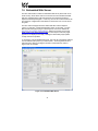
14. Embedded Web Server
The ETH-100 interface contains an embedded web server (also known as an
HTTP server), which allows users to access the unit’s internal data and ASD
data in a graphical manner with web browsers such as Microsoft Internet
Explorer or Netscape Navigator. In this way, the unit and connected drives can
be monitored, configured and controlled from across the room or from across
the globe.
The ETH-100’s web pages are best viewed with either Internet Explorer
version 5.x and later, or Netscape Navigator version 6.x and later. The free
Macromedia Flash player plug-in is also required, and can be obtained at
http://www.macromedia.com/go/getflash. Always ensure that you have the
latest version of the Flash player installed: if some aspect of the web pages
appears to be displayed unusually, installing the latest Flash player update
usually resolves the problem.
To access the unit’s embedded web server, just enter its configured IP address
into the address (URL) field of your web browser. Accessing the ETH-100’s
web page is the same as surfing the Internet’s world-wide web. Refer to
Figure 19 for an example.
Figure 19: Embedded Web Server
42
14.1 Authentication
For security, the ETH-100 requires valid user authentication when the web
page is accessed or the point information is modified. The authentication
request will appear as a browser popup box that will request entry of a user
name and password. The unit contains two different security realms: an
administrator realm and a user realm. Each of these realms has a different
username and password, and applies to different activities. This division of
authentication realms allows a device administrator to retain control of critical
items (such as changing a unit’s IP address or modifying point values and
point definitions) while allowing a device user with appropriate authorization to
monitor point values (i.e. observe the status of the attached drives).
Refer to Figure 20 for a screen shot of the administrator realm authentication
dialog box, and Table 4 for initial factory-set authentication values. Note that
the username and password are case-sensitive, and that once authenticated,
the authentication will remain in effect from that point until all browser windows
are closed.
Figure 20: Administrator Authentication
Table 4: Initial factory-set authentication values
Realm
Username
USER
user
ADMIN
admin
Password
Blank (i.e. do not
enter a password)
Blank (i.e. do not
enter a password)
43
Realm Applies To
Monitoring capabilities
All change actions
14.2 Communication Status Indicators
Figure 21 shows the communication status indicators. These will blink
periodically to show the status of data communication between the web
browser and the unit.
Figure 21: Communication Status Indicators
14.3 Unit Status
Figure 22 shows the non-modifiable unit status information. This includes the
48-bit hardware MAC address, the application firmware version information,
and the current date and time.
Figure 22: Unit Status
14.4 Set Date and Time
Figure 23 shows the submission boxes in which new date and time information
can be entered. Note that the hours are entered in military time format (0-23 =
12AM – 11PM).
Figure 23: Set Date and Time
14.5 Network Configuration
Figure 24 shows the submission boxes in which network configuration
information can be entered. Note that changing the subnet mask or default
gateway will immediately result in a momentary loss of communications: just
44
wait for a moment, or use the “refresh” button on your browser to re-establish
communications. Changing the unit’s IP address, however, will result in a
complete loss of communications, as the unit’s IP address will immediately be
changed from that of the page you are viewing to the new value. To
reconnect, therefore, requires transitioning to the new IP address via the
browser’s “Address” (URL) field.
Figure 24: Network Configuration
14.6 Master Timeout Configuration
Figure 25 shows the submission boxes used to define the parameters
associated with the “master” client timeout determination. The “Master IP” field
entry defines the IP address of the client computer that is designated as the
“master”. The “Master Timeout” field entry defines the number of milliseconds
of inactivity that must transpire on a Modbus TCP/IP socket connection with
the “master” device before the ETH-100 will terminate the socket and perform
its per-point timeout processing. Valid master timeout times are 500ms30000ms (0.5s-30.0s).
Figure 25: Master Timeout Configuration
Because the socket timeout determination is performed on a per-socket
duration basis, note that a certain degree of caution must be exercised when
using the network timeout feature to avoid “nuisance” timeouts from occurring.
Specifically, do not perform inadvisable behavior such as sending a request
from the master device to an ETH-100, and then closing the socket prior to
successfully receiving the unit’s response. The reason for this is because the
ETH-100 will then experience an error when attempting to respond via the
now-closed socket, which will immediately trigger the timeout action. Always
be sure to manage socket life cycles “gracefully”, and do not abandon
outstanding requests.
Modbus TCP/IP sockets initiated from devices other than the “master” device
use a fixed 30s timeout time, and do not perform timeout processing. This
allows devices other than the designated “master” to access the unit for
monitoring or other non-critical access purposes.
45
14.7 Authentication Configuration
Figure 26 shows the submission boxes used to change the user-level and
administrator-level usernames and passwords.
Figure 26: Authentication Configuration
To change, enter your desired username and password (max 11 characters
each), then click “Submit”. Contact ICC if you have forgotten your username
or password for instructions on how to reset them.
14.8 Parent Selection
Each of the 3 ASD channels is automatically defined as a point in the internal
point database. These special points are called “parent points” and their sole
responsibility is simply to define the primary-to-secondary network address
mapping. In the case of the ETH-100, each of the ASD channels is accessed
by appropriate selection of the Modbus TCP/IP unit identifier (UI) field.
Figure 27: Parent Selection
As mentioned in section 13.4.1, the pool of available points in the point
database can be allocated as desired among the three ASD channels. To
view and edit the point assignments for each ASD channel, click on the row in
the “Parents” window for the channel you wish to access. The currentlyselected channel will appear with a white background, and the points
associated with that channel (that parent’s “children”) will be displayed in the
“Children” window (refer to section 14.9).
14.9 Child Selection
When a parent (ASD channel) is selected in the “Parents” windows (refer to
section 14.8), that parent’s children (assigned points) will be displayed in the
46
“Children” window. Refer to Figure 28 for an example. Each row of this
window displays the attribute information for a single point. These attributes
include the Modbus holding register number, the associated coil numbers
(refer to section 13.5), the ASD parameter number, the user-assigned name,
and the point’s current value. The “value” column will display each point’s
current value updated every second. To edit an existing point, click on the row
belonging to the point you wish to edit. The currently-selected point will appear
with a white background, and the attributes of the point will be displayed in the
“Child Edit” window (refer to section 14.10).
Figure 28: Child Selection
To add a new child point to the currently-selected parent (channel), click the
“Create a New Child” button located at the bottom of the “Children” window.
This will bring up an empty point definition in the “Child Edit” window, where
the new point’s information can be entered.
14.10 Child Edit
When a child (point) is selected in the “Children” windows (refer to section
14.9), that child’s attributes (details) will be displayed in the “Child Edit”
window. Refer to Figure 29 for an example.
Figure 29: Child Edit
47
The “Modbus TCP/IP Unit Identifier” and “Toshiba ASD Channel” fields are for
reference only, and indicate the same selection that was previously made in
the “Parents” window (refer to section 14.8). The remainder of the displayed
attributes, however, are editable.
The “Holding Register” and “ASD Parameter” entry boxes allow assignment of
their respective information. The “Point Name” entry box accepts a userdefined name for the point (max 16 characters). The “Timeout Value” entry
box and associated “Enabled/Disabled” button allow for definition of a network
timeout value and whether or not this point will participate in network timeout
processing (refer to section 13.2). Lastly, the “Current Value” entry box
indicates (when editing an existing point) the point’s value at the time the point
was selected for editing, and accepts new values to be written to the point (to
control an attached drive, for example).
Note that the Radix Selection buttons (refer to section 14.11) allow dynamic
modification of the display and entry format of the “ASD Parameter”, “Timeout
Value” and “Current Value” fields.
After changing or entering new attribute information, the changes can be
written to the unit by selecting the “OK” button. Prior to selecting the “OK”
button, changes may be aborted at any time by selecting the “Cancel” button.
To delete a point, select the “Delete” button.
When configuring the point database, there are several rules that must be
followed:
•
Only one child per parent may have a specific holding register number.
•
Modbus holding register numbers must be 1-65535.
•
ASD parameter numbers must be 0-65535 (0x0000-0xFFFF).
•
Modbus holding registers 9998 and 9999 are reserved for Universal
Access registers and therefore cannot be programmed as a point’s
holding register number. Refer to section 13.4.3 for more information.
14.11 Radix Selection
Figure 30 shows the radix selection buttons. These selection buttons allow
changing the data display and entry radix between decimal and hexadecimal
formats. This change applies to the “ASD Parameter” and “Value” fields both
in the Child Selection (section 14.9) and Child Edit (section 14.10) windows.
Figure 30: Radix Selection
48
14.12 Error Code Reference
Figure 31 shows the error code reference table. These error codes may
appear in certain situations in the “Value” fields in the Child Selection (section
14.9) and Child Edit (section 14.10) windows. If an error code is indicated,
confirm the validity of the ASD register being accessed, check the ASD
communication cabling, and review the troubleshooting information contained
in section 13.6.
Figure 31: Error Code Reference
14.13 Allocated Sockets Report
Figure 32 shows the allocated sockets report. This section indicates the
number of Modbus TCP/IP sockets that are currently allocated by network
clients (0-8).
Figure 32: Allocated Sockets Report
49
15. Firmware Updates
The ETH-100’s embedded firmware resides in flash memory that can be
updated in the field. Firmware updates may be released for a variety of
reasons, such as custom firmware implementations, firmware improvements
and added functionality as a result of user requests.
ICC is continually striving to enhance the functionality and flexibility of our
products, and we therefore periodically release new embedded firmware to
achieve these goals and meet customer requests. Flash firmware files and all
related documentation (such as updated user manuals) can be downloaded as
complete board support packages (referred to as BSPs) from
http://www.iccdesigns.com. It is suggested that users check this Internet site
prior to installation, and then periodically afterwards to determine if new
support packages have been released and are available to upgrade their units.
15.1 Requirements
Besides the new firmware file, firmware updates require a PC with a Windows
operating system (Windows 95 or later) and a serial port, the RFU PC
application (refer to section 15.3), and the MMI cable included with the
interface kit (ICC part number 10425).
Please be sure to read the firmware release notes and updated user’s manual
(included with the BSP) for any important notices, behavior precautions or
configuration requirements prior to updating your firmware. For example,
upgrading to a new firmware version may affect user-defined point files: prior
to starting an update procedure always back up your point files to a PC for
later recovery if necessary.
15.2 Connection
The ETH-100 ships from the factory with a dust cover installed in the MMI port.
To minimize contamination of the port’s electrical contacts, keep this dust
cover in place whenever the MMI port is not in use.
IMPORTANT: Note that the ETH-100 will not be operating its system control
and communication tasks while its internal firmware is being updated.
Therefore, be sure to shut down the system to a known safe state prior to
initiating the firmware update procedure.
Connect the RJ45 end of the MMI cable to the MMI port, and connect the other
end to the computer’s serial port. Move switch SW1 #1 to the “ON” (down)
position: this will place the ETH-100 into the “firmware download” mode.
Whenever switch SW1 #1 is “ON”, the ETH-100 can only download firmware to
50
its flash: all other application functions (such as communications, console
access etc.) will be disabled.
15.3 Using the RFU Utility
Support for downloading new application firmware to the interface is provided
by the free Rabbit Field Utility (RFU), which is a 32-bit application that runs on
Microsoft Windows platforms. The RFU utility can be downloaded from ICC’s
home page at http://www.iccdesigns.com. When downloading a new
application BSP, always confirm that you also have the latest version of RFU,
as new .BIN firmware files contained in BSPs may require functionality found
only in the most recent RFU versions for successful downloading.
The remainder of this section will detail the RFU utility configuration and
firmware download procedures.
15.3.1 Required Files
When first downloaded, the RFU utility files are compressed into one selfextracting .EXE distribution file. Create a folder (such as c:\RFU), place the
distribution file in this folder, and then execute it. This will extract the
compressed files. The distribution file is then unneeded and can be deleted if
desired. To run the RFU utility, double-click on the RFU.EXE file icon.
15.3.2 First-Time Configuration
The first time the RFU utility is run on a computer, several configuration items
need to be confirmed. These configuration items are retained in the
computer’s registry from that point on, so reconfiguration is not required unless
certain parameters (such as which serial port to use on the computer) are
changed.
The two configuration items that need to be confirmed are the communications
characteristics and bootstrap loaders path. First, select the
“Setup…Communications” menu item (refer to Figure 33).
51
Figure 33: RFU Main Screen
The Communications Options window shown in Figure 34 then appears.
Confirm that the settings are as shown, with the possible exception of the
“Comm Port” settings, which depends on the COM port you are using. Click
“OK” when complete.
Note: It is possible that certain computers may have difficulty communicating
at a sustained 115kbaud rate, which may result in communication errors during
firmware downloading. If this occurs, try setting the “baud rate” parameter
shown in Figure 34 to a lower value.
Figure 34: Communications Options Window
Next, select the “Setup…File Locations” menu item from the main screen. The
“Choose File Locations” window shown in Figure 35 then appears. Confirm
52
that the correct paths to the referenced files are entered. Enter the correct
paths if necessary.
Figure 35: Choose File Locations Window
15.3.3 Transmitting Firmware Files
When a board support package (BSP) has been downloaded and unzipped,
the flash firmware file will be the one with “.BIN” as its file name extension.
Once the RFU utility has been configured, the flash firmware files can be
downloaded to the interface by two different methods. The simplest way is to
drag the application firmware .BIN file’s icon and drop it onto the RFU utility’s
main screen. This will automatically initiate the download process.
Alternatively, select the “File…Load Flash Image” menu item (refer to Figure
36).
Figure 36: Load Flash Image Menu Selection
The flash image (.BIN file) selection window will then appear (refer to Figure
37). Browse to the location of the flash image file and select it. Clicking “OK”
will then initiate the download process.
53
Figure 37: Flash File Selection Window
While downloading, the RFU utility will indicate the download status. Once
complete, summary information will be displayed in the bottom status bar (see
Figure 38).
Figure 38: Summary Information
15.4 Wrap-Up
Once downloading is complete, close the RFU utility, move switch SW1 #1 on
the ETH-100 unit back to the “OFF” (up) position to leave “firmware download”
mode, and cycle power momentarily to the unit by either powering down all
connected drives or momentarily removing all drive communication cables
from the unit.
When the unit powers up again, it will be running the new application firmware.
If the new firmware version release notes indicate that point files might need to
be reloaded, then do so at this point.
When completed with MMI port use, remove the MMI cable and replace the
MMI port dust cover to minimize contamination of the port’s electrical contacts.
54
16. Notes
55
56
ASD INTERFACE SERIES
ICC
INDUSTRIAL CONTROL COMMUNICATIONS, INC.
ICC
INDUSTRIAL CONTROL COMMUNI
COMMUNICATIONS,
CATIONS, INC.
2204 Timberloch Place, Suite 250
The Woodlands, TX USA 77380-1049
Tel: [281] 292-0555 Fax: [281] 292-0564
http://www.iccdesigns.com
Printed in U.S.A
ETH-100
ETHERNET COMMUNICATIONS INTERFACE
FOR TOSHIBA ADJUSTABLE SPEED DRIVES
February 2004
ICC #10449-2.100-000