1
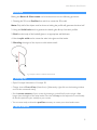
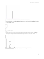
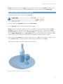
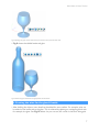
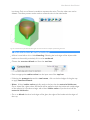
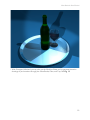
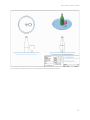
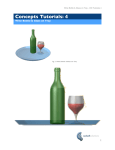
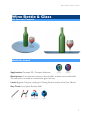
Wine Bottle & Glass Tutorial
Wine Bottle & Glass
CSI Concepts Tutorials
About this tutorial
Application: Concepts 3D / Concepts Unlimited
Description: In this tutorial we learn to draw profiles, to lathe, and to shell solids.
The end result is a model of a wine bottle, glass, and tray.
Level: Beginner. Requires reading the ‘Getting Started’ section of the User Manual.
Key Tools: Line, Spline, Revolve, Shell
1
Wine Bottle & GlassTutorial
Overview
Making the Bottle & Glass scene can be broken down into the following processes:
1. Drawing the 2D curve Profiles from which to create the 3D model.
Note: Only half of the object need be drawn as lathing the profile will generate the other half.
2. Using the Solid Lathe tool to generate the bottle, glass & tray from their profiles.
3. Shell out the body of the bottle & glass to an appropriate wall thickness.
4. Use the split solid tool to create the wine in the glass and the bottle.
5. Blending the edges of the objects to add realistic detail.
Fig 1. Profile A shown is ‘lathed’ around axis B
1. Setting Up
• Open Concepts Unlimited or Concepts 3D
• Change view to Front View (View>front). [Alternately, right-click on the drawing window
and use the contextual menu]
• Set the zoom extents of your screen by drawing a vertical line from the origin a little
longer than the height of the wine bottle. Press the ‘e’ key on the keyboard to comfortably
fit that line (and thus your model) to your screen.
• You are now ready to draw the profiles necessary to create your wine bottle scene.
2. Draw Profiles
2
Wine Bottle & Glass Tutorial
• First, right-click on the origin and place a horizontal construction line. This will represent our
base line. (the surface on which the tray would sit). See Fig 2 below:
Fig 2. Construction Lines
• Use the Single Line tool to draw the center-line axis of the bottle and the glass. The tray
beneath shares the same central axis as the bottle. (ie: the bottle sits right in the middle of
the tray)
• Choose the Single Line tool from the tool bar.
• Click once at the origin to start the center axis line for the tray and bottle.
• Move the cursor vertically up the screen and click an arbitrary distance from the origin
making sure you see the helper-line of the cursor and the along z mark at the origin. Then
type the height you wish the bottle to be from the base surface. (We have used a height of
12 inches or 300 mm). The line will adjust to the height you type.
• Move to the right of the bottle axis and draw another vertical line to represent the centerline axis of the wine glass. The height of the glass should be a little over half the height of the
wine bottle. See Fig 3 below.
3
Wine Bottle & GlassTutorial
Fig 3. You should now have one construction base-line, one bottle axis and one glass axis
• Use a combination of the line, spline and arc tools to generate the full profile of the glass
as seen in Fig 4 below.
Fig 4. Glass profile
• Use the same tools to then generate the profiles of the bottle and the tray too. See Fig 5.
You may find it helps to have a wine bottle and a glass at hand to study their shapes.
Fig 5. Complete profiles for the bottle, the glass and the tray
4
Wine Bottle & Glass Tutorial
• Note: Ensure there are not gaps in your profiles and that they are planar. These are the
two factors that can cause a profile to fail when used with a tool such as solid lathe.
4. Next, lathe the profiles into solids
• Choose the lathe solid tool from the tool bar
• As ever, follow the prompts beneath the tool name
• First, a profile must be selected. Begin with the glass
• Note: Instead of clicking one line at a time, a profile can automatically be traced by rightclicking on one of the curves that make up the profile of the glass or the bottle. A contextual menu will appear: choose Select Chain. Provided your profile is good (ie: there
are no gaps, duplicate lines or branched lines), the entire profile will be selected. (Select
Chain can be a great time-saver when selecting profiles or testing profiles for gaps).
• After selecting the profile, you need to select the line or axis around which to lathe it. This
is it’s center-line. The lathed objects should appear immediately. See Fig 6.
• After lathing the glass, lathe the bottle and then the tray.
Fig 6. The raw lathed solids are shown here before shelling
5
Wine Bottle & GlassTutorial
5. Shelling your new solids
• The new solids must now be shelled to an appropriate wall thickness.
• Choose the shell tool from the tool bar.
• Begin with the bottle. Click somewhere on the object
• Then click on the top of the bottle where the opening should be. An ambiguity pop-up
will appear. Select the appropriate open face from the pop-up. See Fig 7 below.
Fig 7. Selecting the open face using the ambiguity pop-up
• Note: An ambiguity pop-up is a window that appears when you select an object, and
there is no one clear face or object that Concepts can pick. You must select the appropriate entry.
• Tool hint: Press shift if you wish to select multiple open faces. Click on the background (ie
no object if you wish to have a hollow object but no open faces). Press the option key to
keep the hollowed out section.
• Go on to shell the glass. Because the constricted neck shape of a wine glass is difficult for
the shell tool to deal with, better results will be acheived if you split the glass at the neck using the infinite plane and split solid tools. Be sure to use a z-station infinite plane at the neck
of the glass. See Fig 8.
6
Wine Bottle & Glass Tutorial
Fig 8 Splitting the glass at the neck allows for a better result from the shell tool
• Fig 9 shows the shelled bottle and glass
Fig 9 Bottle and glass shelled to an appropriate wall thickness
6. Creating the wine for the glass & bottle
• After shelling the objects, more detail can be added for extra realism. For example, wine can
be added to the bottle and to the glass. This is achieved by splitting an overlapping block with
for example, the glass. See Fig 10 below. As you can see, this results in the block being split
7
Wine Bottle & GlassTutorial
into three. Only one of these is needed to represent the wine. Thus the other two can be
deleted. The same process can be used to create the wine in the wine bottle.
Fig 10. A solid block is split with the wine glass in order to achieve a shape representing the wine
7. Blending edges to add realistic detail
• All that is now left to do is a little blending. Softening the hard edges of the objects adds
realism to the model, particularly if it is to be rendered.
• Choose the constant blend tool from the tool bar.
• Enter an appropriate radius value into the input area of the top bar.
• Following the prompts beneath the tool name, click on the hard edges of the glass top
to apply constant blends.
• Note: A blend radius value typically needs to be less than the material thickness.
On an object like a glass where the blends will be applied to both the inside and outside edges
of the material, it is prudent to begin with a blend radius value of just less than half the
material thickness.
• Go on to blend the other hard edges of the glass, the edges of the bottle and the edges of
the tray.
8
Wine Bottle & Glass Tutorial
Fig 10. Shows the application of a constant blend to the top edge of the wine glass
• Congratulations, Fig 11 shows your finished scene!
Fig 11. Finished Bottle, Glass & Tray
8. Additional Notes and Comments
• If you have Concepts Unlimited, try rendering the Bottle, Glass & Tray with realistic materials. See Fig 12 below.
9
Wine Bottle & GlassTutorial
• With Concepts Unlimited, you can also use the Model to Sheet tool to generate elevation
drawings of (and sections through) the Wine Bottle, Glass, and Tray. See Fig 13
10
Wine Bottle & Glass Tutorial
Fig 13. Drawing of the Bottle, Glass & Tray using Model to Sheet in Concepts Unlimited
11
Wine Bottle & GlassTutorial
Notices
All terms mentioned in this book that are known to be trademarks or service marks have been appropriately capitalized. CSi cannot attest to the accuracy of this information. Use of a term in this book should not be regarded as
affecting the validity of any trade mark or service mark.
Copyright © 2006 CSI
All rights reserved. No part of this publication may be reproduced or used in any form by any means without the
prior written permission of CSi. The information contained in this publication is believed to be accurate and reliable. However, CSi makes no representation or warrantees with respect to the program material described within
and specifically disclaims any implied warranties of merchantability or fitness for any particular purpose. Further,
CSi reserves the right to revise the program material and make changes therein from time to time without obligation to notify the purchaser of the revisions or changes. In no event shall CSi be liable for any incidental, indirect
special or consequential damages arising out of the purchaser’s use of the program material.
Revision 1.0
Jol Yates (8 May 05)
Revision 1.1
Tim Olson (25 Jan 06)
www.csi-concepts.com
12