1
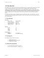
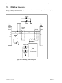
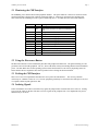
USBdebug 700 User’s Manual M200037-00 June 1998 Preliminary Sycard Technology 1180-F Miraloma Way Sunnyvale, CA 94086 (408) 749-0130 (408) 749-1323 FAX http://www.sycard.com USBdebug 700 User Manual Page 1 1.0 Introduction The USBdebug 700 is a debug tool for the Universal Serial Bus (USB). It is designed to allow technical users of USB a means to monitor the status of the bus and to attach various test equipment directly to the USB signal lines. USBdebug is inserted between the peripheral and host. Six LED status indicators show the current bus status. These indicators display voltage, activity, bus reset and over-current conditions. To facilitate debug, all signal and power pins of the USB interface are accessible via clearly marked test points. Jumper blocks allow any signal or power pin to be isolated. A jumper block on Vcc allows the user to insert a series current meter to accurately measure peripheral current. To facilitate plug-and-play testing the USBdebug integrates a push-button disconnect. The “Disconnect” button will momentarily disconnect the USB peripheral from the host. The disconnect button will isolate all four signal and power pins from the peripheral. 1.1 Specifications Electrical Supply Voltage Current Consumption Vcc OK LED tolerance 100mA overcurrent 500mA overcurrent 9VDC @ 500mA 50mA Max 4.4V +-3% 100mA +- 4% 500mA +- 4% Physical Height Width Length Weight Environmental Temperature Humidity 1.0” 4.0” 2.4” 3 oz 0 - 50 degrees C 0 - 95 % Non condensing 1.2 Packing List The USBdebug package includes the following: • • • USBdebug 700 Test Unit USB A-B 20/28 Gauge 1 meter cables USBdebug User’s Manual 1.3 Related Documentation Universal Serial Bus Specification - Revision 1.0 Universal Serial Bus Architecture - Mindshare, Inc. M200037-00 1998 Sycard Technology Page 2 USBdebug 700 User Manual 2.0. USBdebug Operation The USBdebug is inserted between the peripheral and host. showing all the major functional blocks. Figure 2.0-1 is a block diagram of the USBdebug 700, Activity Logic Reset Host Side Periph Side USB B Conn Jumper Block Disconnect Switch D+ D+ D+ D- D- D- D+ D- GND GND USB A Conn GND Shield Shield Vcc Vcc Vcc JP2 Power Voltage OK 100mA Voltage and Current Comparators 500mA Figure 2.0-1 USBdebug 700 Block Diagram 1998 Sycard Technology M200037-00 USBdebug 700 User Manual Page 3 2.1 Monitoring the USB Interface The USBdebug 700 is inserted between the peripheral and host. The square USB “B” connector is connected via the supplied USB cable to the host side, while the rectangular USB “A” connector is connected to the peripheral side. Once connected, the USBdebug becomes a passive monitoring device. Six LEDs show the status of the USB bus. Indicator Power On State ON OFF Description Host power active Host power not active or cable not connected to host Power OK ON Host power > 4.4V OFF Host power < 4.4V >500mA ON Current consumed by peripheral > 500mA OFF Current consumed by peripheral < 500mA >100mA ON Current consumed by peripheral > 100mA OFF Current consumed by peripheral < 100mA Activity OFF No activity including SOF Dim Only SOF active Bright Higher levels of activity USB Reset ON USB Reset Detected or host port disabled OFF USB Reset not active Table 2.1-1 Indicator Descriptions 2.2 Using the Disconnect Button The Disconnect button is used to momentarily disconnect the peripheral from the host. All signals including Vcc and ground are removed from the peripheral. The Vcc, Power-OK LEDs will stay lit indicating that the host still maintains power. The time that it takes for the operating system to detect the disconnect event will vary depending on the OS. Insure that the OS has completed its disconnect operation before releasing the disconnect button. 2.3 Probing the USB Interface There are two sets of four pin headers that allow the user to probe the USB interface. The user may attach an oscilloscope or voltmeter to either J1 or J2. The test equipment ground may be connected to the GND pin on JP1, JP2 or a separate GND test point right above ZP4. 2.4 Isolating Signals In the event that the user wishes to disconnect any signal, the jumper blocks located at ZP4 can be removed. Probing J2 accesses the signals on the host side and J1 accesses signals on the peripheral side. Line impairments may also be added directly to J1 and J2. M200037-00 1998 Sycard Technology Page 4 USBdebug 700 User Manual 2.5 Measuring Peripheral Current The USBdebug’s current measurement circuitry is designed to indicate that current exceeds two fixed values of 100mA and 500mA. The USBdebug provides two alternate ways to measure peripheral current. The first way involves using the internal 0.2 ohm 1% tolerance series current sense resistor. To measure current, place a DC voltmeter across JP2. The peripheral current can be calculated as follows: I = (measured voltage) / 0.2 ohm For example, if the user measures 0.5V across JP2, then the peripheral current is as follows: 40mV / 0.2 ohm = 200mA Measurements with a current meter may also be used. Remove the Vcc jumper on ZP4 and connect the series current meter between the two pins. For accurate readings, it is also recommended that the internal series current sense resistor be removed from the circuit by placing a shorting jumper on JP2 (ISENSE). 2.6 Voltage Margin Testing All new USB designs should be tested to insure that the peripheral operates per specification under worst case Vcc low and high conditions. The USBdebug can facilitate this testing by allow the user to insert an adjustable power supply to power the peripheral. The user can simply disconnect the Vcc jumper at ZP4 and wire in the external power supply. Testing under worst case conditions can be accomplished by varying the external power supply. 1998 Sycard Technology M200037-00 USBdebug 700 User Manual Page 5 3.0 - Hardware Notes This section describes some useful information on how the USBdebug was implemented. Shield Ground - The USBdebug does not connect the USB digital ground to the USB shield ground. In applications where it would be desirable to connect Shield Ground to USB ground, there is a SMT resistor pad at location R23 on the USBdebug board. If users wish to make this modification, they must disassemble the USBdebug and install a shorting resistor on R23. USBdebug circuitry current consumption - USBdebug requires a certain amount of power to run its on-board circuitry. This amount of current depends greatly on the state of the LED indicators. Maximum current consumption is 50mA. The on-board current measurement circuitry is designed to measure only the peripheral current and not the current drawn by the USBdebug circuitry. M200037-00 1998 Sycard Technology Page 6 USBdebug 700 User Manual 4.0 - Common Problems This section will describe some of the common problems encountered while trying to use the USBdebug. Activity Light Stays On - The activity light will light at approximately 50% brightness during idle times when only SOF packets are being sent. The brightness should increase in proportion to the bus activity. Overcurrent LEDs don’t light in an overcurrent situation - Make sure that JP2 (ISENSE) is not shorted. Shorting JP2 disables overcurrent detection. 1998 Sycard Technology M200037-00