1
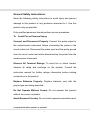
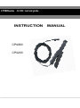
\\\\
CP4000series AC/DC current probe
INSTRUCTION
CP4060
CP4200
MANUAL
General Safety Instructions:
Read the following safety instructions to avoid injury and prevent
damage to this product or any products connected to it. Use this
product only as specified.
Only qualified personnel should perform service procedures.
To
Avoid Fire or Personal Injury
Connect and Disconnect Properly. Connect the probe output to
the measurement instrument before connecting the probe to the
circuit under test. Disconnect the probe input and the probe ground
from the circuit under test before disconnecting the probe from the
measurement instrument.
Observe All Terminal Ratings. To avoid fire or shock hazard,
observe all rating and markings on the product. Consult the
instruction manual for further ratings information before making
connections to the product.
Replace Batteries Properly. Replace batteries only with the
proper type and rating specified.
Do Not Operate Without Covers. Do not operate this product
without the covers or panels.
Avoid Exposed Circuitry. Do not touch exposed connections and
components when power is present.
1
Do Not Operate With Suspected Failures. If you suspect there is
damage to this product, have it inspected by qualified service
personnel.
Do Not Operate in Wet/Damp Conditions.
Do Not Operate in an Explosive Atmosphere.
Keep Product Surfaces Clean and Dry.
Safety Terms and Symbols:
Terms in This Manual. These terms may appear in this manual:
WARNING. Warning statements identify conditions or practices
that could result in injury or loss of life.
CAUTION. Caution statements identify conditions or practices
that could result in damage to this product or other property.
Terms on the Product. These terms may appear on the product:
DANGER indicates an injury hazard immediately accessible as you
read the marking.
WARNING indicates an injury hazard not immediately accessible
as you read the marking.
CAUTION indicates a hazard to property including the product.
Symbols on the Product. These symbols may appear on the
product:
Attention refer to operation Instructions.
2
This instrument has double insulation.
Getting Started:
The current probe enables a general purpose oscilloscope to
display AC and DC current signals up to 500 amps Peak (180 A
RMS).
The current
probe can also make AC and
DC
measurements with a multimeter by using the recommended
accessory MT-246N
(BNC-to-banana) plug adapter.
PIC 1
Output Into
Scope
Press Button
Battery Cover
Test Position
Max. 11¢Wire
DC Zero Offset
3
Range Selection
(Power On/Off)
Shows the controls and indicators on the current
probe.
Control/Indicator
Description
Current flow symbol. The arrow shows the probe’s
polarity convention for measuring current flowing
from positive to negative.
Zero adjustment. Rotate to adjust the probe output
to zero when there is no current present. It may also
be used to offset a DC signal component. Zeroing is
not needed for AC measurements unless your
instrument cannot isolate a DC component (if
present).
OFF/Range switch. Slide the switch from OFF to
either the 5 mV/A or 50mV/A range. When either
range is selected, the probe is turned on, and the
green battery indicator lights. If the indicator does not
light, see Battery Notes and Battery Installation on
page11.
Battery indicator. The green battery indicator lights
when the probe is turned on. For more information,
see Battery Notes and Battery Installation on page11.
Overload indicator. The red overload indicator lights
if the measured signal is greater than the selected
range capacity. Switch the probe to 10 mV/A if
possible, or remove the probe from the circuit.
Specifications:
These characteristics apply to an adjusted CP4000 AC/DC Current
Probe installed on an oscilloscope of any brand. The oscilloscope
must be warmed up for at least 20 minutes and be in an
environment with the temperature at 10℃~30℃ and the humidity at
0~80.
4
Size
231 mm x67 mm x 36 mm
Maximum Conductor Size
10.3 mm
Cable Length
200 cm
Weight
310 g (without battery)
Environmental Characteristics
Temperature
Working
0°C to +50°C
(+32°F to +122°F)
Storage
-20°C to +80°C
(-4°F to +176°F)
Humidity
0°C to 40°C, 95% humidity
40°C to 50°C, 45% humidity
Pollution Degree
2
CP4060
Basic Operation:
Before using the probe, the batteries must be installed.
WARNING!
Do not clamp the probe onto circuits with voltages greater
than 600VAC. Personal injury or damage to the probe may
result.
Always connect the CP4060 current probe output to the
5
instrument before clamping onto the circuit under test.
1. First connect the current probe BNC connector to BP-250
(double BNC connection cable) then connect to oscilloscope input.
Start by setting the oscilloscope voltage input channel to DC volts,
and the voltage sensitivity scale to 5m V/div.
2. Move the OFF/ Range switch to the 5 mV/A or 50 mV/A position
to turn on the probe.
(※The CP4060 current probe has a green LED power/battery
indicator. If the LED does not light, replace the battery or use
specified power adaptor.)
3. Use the ZERO adjustment to zero or offset the probe output
detection of residual magnetic DC charges.
4. Connect the probe to the circuit by opening the jaws and
clamping around the conductor.
NOTE. Clamping around both the “hot” and neutral wires may
give you a zero reading.
(Remember to unclamp the probe from the conductor before
disconnecting it from your meter or instrument).
5. Adjust the probe channel and oscilloscope’s time base as
necessary to get a clear and stable view of the signal. Set the
oscilloscope input to DC volts to see both the AC and DC currents;
set the channel to AC to see the AC current only.
6
6.The current drawn by different devices look much different than
that of others. While the RMS current can only be used in low
frequency current, the momentary peaks may be quite high.
7.Congratulations on your purchase of the CP4060, a
multifunctional current probe. When connecting to a digital meter,
use the recommended MT-246N (BNC-to-banana adapter).
Connect the black lead to the meter COM (black letters on the
meter), and the red lead to the VΩ input (red letters on the meter).
8.To measure only AC current, set the meter to measure AC volts.
9.To measure DC current, set the meter to measure DC volts. Note
the current convention arrow on the probe to get the proper polarity
reading.
10.To increase the measurement sensitivity of the CP4060 current
probe, loop additional turns of the wire under test through the jaws.
See Figure 1. The sensitivity of the CP4060 current probe is
multiplied times the number of loops in the jaws. For example:
50mV/A X5turns=250mV/A
Figure 1
7
Electrical Characteristics
Current Range
5mV/A ;
50mV/A
±2% ±0.4 mA at 50mV/A
(0.4mA to 10 A peak range)
DC Accuracy, typical
±2% ± 1A at 5mV/A
(1A to 60 A peak range)
Maximum Working Current
60A
Frequency Range
DC to 100KHz (-3 dB)
Rise time,typical
2.5uS
Noise(Max)
2mV pk-pk
Battery
9Vbattery
Voltage and current ratings
Maximum working
current(A)
Maximum Working
voltage (V)
Maximum floating
voltage (V)
Range
5mV/A
Range
50mV/A
Maximum Working
voltage (V)
Maximum floating
voltage (V)
DC
50
5
600
600
DC + peak
AC
50
5
600
600
AC peak
50
5
600
600
AC
peak-peak
100
10
1200
-
RMS CAT III 35.4
3.54
600
600
RMS
35.4
3.54
600
600
RMS CAT I
35.4
3.54
600
600
Rating
Rating
測定
CAT II
CP4200
Basic Operation:
Before using the probe, the batteries must be installed.
8
WARNING!
Do not clamp the probe onto circuits with voltages greater
than 600V AC. Personal injury or damage to the probe may
result.
Always connect the CP4200 current probe output to the
instrument before clamping onto the circuit under test.
1. First connect the current probe BNC connector to BP-250
(double BNC connection cable) then connect to oscilloscope input.
Start by setting the oscilloscope voltage input channel to DC volts,
and the voltage sensitivity scale to 5m V/div.
2. Move the OFF/ Range switch to the 5 mV/A or 50 mV/A position
to turn on the probe.
(※The CP4200 current probe has a green LED power/battery
indicator. If the LED does not light, replace the battery or use
specified power adapter.)
3. Use the ZERO adjustment to zero or offset the probe output
detection of residual magnetic DC charges.
4. Connect the probe to the circuit by opening the jaws and
clamping around the conductor.
NOTE. Clamping around both the “hot” and neutral wires may
give you a zero reading.
9
(Remember to unclamp the probe from the conductor before
disconnecting it from your meter or instrument).
5. Adjust the probe channel and oscilloscope’s time base as
necessary to get a clear and stable view of the signal. Set the
oscilloscope input to DC volts to see both the AC and DC currents;
set the channel to AC to see the AC current only.
The current drawn by different devices look much different than that
of others. While the RMS current can only be used in low frequency
current, the momentary peaks may be quite high. Figure 3 shows
the difference between the line current drawn by a resistive load
and a motor controller.
Congratulations on your purchase of the CP4200, a multifunctional
current probe. When connecting to a digital meter, use the
recommended MT-246N (BNC-to-banana adapter). Connect the
black lead to the meter COM (black letters on the meter), and the
red lead to the VΩ input (red letters on the meter).
To measure only AC current, set the meter to measure AC volts.
To measure DC current, set the meter to measure DC volts. Note
the current convention arrow on the probe to get the proper polarity
reading.
To increase the measurement sensitivity of the CP4200 current
probe, loop additional turns of the wire under test through the jaws.
10
See Figure 2. The sensitivity of the CP4200 current probe is
multiplied times the number ofloops in the jaws. For example:
50mV/A X5turns=250mV/A
Figure 2
Electrical Characteristics
Current Range
5mV/A ;50mV/A
±2% ±0.4 mA at 50mV/A
(0.4mA to 10 A peak range)
DC Accuracy, typical
±2% ± 1A at 5mV/A
(1A to 200 A peak range)
Maximum Working Current
200A
Frequency Range
DC to 150KHz (-3 dB)
Rise time,typical
2.3uS
Noise(Max)
2mV pk-pk
Battery
9Vbattery
11
Voltage and current ratings
Maximum working
current(A)
Maximum Working
voltage (V)
Maximum floating
voltage (V)
Range
5mV/A
Range
50mV/A
Maximum Working
voltage (V)
Maximum floating
voltage (V)
DC
100
10
600
600
DC + peak
AC
100
10
600
600
AC peak
100
10
600
600
AC
peak-peak
200
20
1200
-
RMS CAT
III
RMS
70.7
7.07
600
600
70.7
7.07
600
600
RMS CAT I
70.7
7.07
600
600
Rating
Rating
測定
CAT II
1. Notes on Battery and Power Converter:
The CP4000 current probe uses a single square 9 V battery. This
machine is a high power product. Please use the specified alkaline
battery.
As the battery in the CP4000 current probe is drained, significant
gain errors may occur. The green LED will continue to light until a
low battery voltage of 6.5 V is reached.
If probe gain errors are detected, replace the battery with a fresh
one.
If not using this item(more than 1 week),we suggest you remove
the battery from the compartment. This is because heating will
result in battery leakage, and battery electrolyte will rust the circuit
board,thus creating major damage. Furthermore, batteries are high
12
pollution products and therefore by reducing their usage, we will in
turn protect the environment.
This will avoid leakage of battery since the quality of the batteries is
something that is out of our control.
2. Battery Installation:
(1) Remove the probe from the circuit.
(2) Open the battery compartment by taking the cover off.
Install/replace the battery.
(3) While observing polarity, attach the new alkaline battery to the
battery connector buttons and place the battery in the specified
area.
(4) Place the cover back and lightly tighten the cover in place.
3. Cleaning:
To clean the probe exterior, use a soft cloth dampened in a solution
of mild detergent and water. To clean the core, open the jaw and
clean the exposed core surfaces with a cotton swap dampened
with isopropyl alcohol (isopropanol). Lubricate the jaws mating
surfaces with light oil.
Do not clean with solvents or abrasives. Do not immerse the probe.
4. Preparation for Shipment
Our company has designed a special box to be used for CP4000,
13
convenient for storage and shipment. Please do not discard it.
If the original packaging is unfit for use or not available, use the
following packaging guidelines:
(1) Use a sturdy shipping carton having inside dimensions at least
one inch greater than the probe dimensions.
(2) (2) Put the probe into a plastic bag or wrap to protect it from
dampness.
(3) Place the probe into the box and stabilize it with light packaging
material.
(4) Seal the carton with shipping tape.
Replaceable Parts:
The CP4000 AC/DC Current Probe is shipped with the following
items:
One instruction manual
One 9V battery
Recommended accessory for use with digital meter:
One BNC to banana plug adapter
Product number MT-246N. Designed with color fool proof design to
avoid polarity mistake when connecting to digital meter.
The CP4000 series does not have any user repairable assemblies.
If you should, have trouble with your probe, contact your local
Service Center or representative for help.
14