1
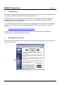
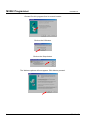
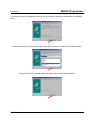
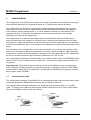
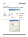
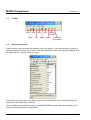
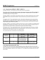
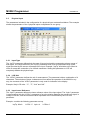
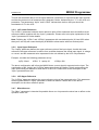
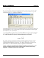
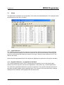
M3092 Programmer
User’s Manual
M3096B-33 E
Copyright © 2001 SELCO
SELCO A/S
Betonvej 10 - DK-4000 Roskilde
Denmark
Phone: 45 7026 1122 - Fax: 45 7026 2522
e-mail: [email protected]
www.selco.com
M3092 Programmer
M3096B-33 E
Table of contents
1
INTRODUCTION ........................................................................................................................ 4
2
SOFTWARE INSTALLATION .................................................................................................... 4
3.
CONFIGURATION ..................................................................................................................... 8
3.1
Communication cable ........................................................................................................ 8
3.2
Program Menus ................................................................................................................. 9
3.3
Toolbar............................................................................................................................. 10
3.4
General Parameters......................................................................................................... 10
3.4.1
Initialization (OFF / CONFIG / CONF+GEN)............................................................ 11
3.4.2
Function Test (OFF / ON) ........................................................................................ 11
3.4.3
Device Number (1 to 62) .......................................................................................... 11
3.4.4
Protocol (MODBUS / SELCO BUS) ......................................................................... 11
3.4.5
RS232 Baud Rate (600 to 19200)............................................................................ 11
3.4.6
RS485 Baud Rate (600 to 19200)............................................................................ 11
3.4.7
Remote LED Test (OFF / ON).................................................................................. 11
3.4.8
Remote Reset (OFF / ON) ....................................................................................... 11
3.4.9
Reset Function (DEFAULT / RESET 2 / RESET 3) ................................................. 12
3.4.10
Output Follows Alarm (OFF / ON)............................................................................ 12
3.4.11
Block (OFF / +REF / -REF) ...................................................................................... 13
3.4.12
Alarm Out Inverted (OFF / ON) ................................................................................ 13
3.4.13
Second Alarm Pulse (OFF / ON).............................................................................. 13
3.4.14
Hysteresis in % (0 to 12.5) ....................................................................................... 13
3.5
2
Physical Input................................................................................................................... 14
3.5.1
Input Type ................................................................................................................. 14
3.5.2
LCD Unit ................................................................................................................... 14
3.5.3
Input Lower Reference.............................................................................................. 14
3.5.4
LCD Lower Reference .............................................................................................. 15
3.5.5
Input Upper Reference.............................................................................................. 15
3.5.6
LCD Upper Reference .............................................................................................. 15
3.4.7
Miscellaneous ........................................................................................................... 15
3.6
Logical Input..................................................................................................................... 16
3.7
Alarm................................................................................................................................ 17
3.7.1
Input Reference ........................................................................................................ 17
3.7.2
Dynamic Reference, <>± Operator & Set Point ........................................................ 17
SELCO A/S
M3092B-33 E
M3092 Programmer
3.7.3
LCD Description........................................................................................................ 18
3.7.4
Delay......................................................................................................................... 19
3.7.5
LED........................................................................................................................... 19
3.7.6
Output ....................................................................................................................... 19
3.7.7
Flags ......................................................................................................................... 19
3.7.7.1
Block ................................................................................................................... 19
3.7.7.2
Control ................................................................................................................ 20
3.7.7.3
Hysteresis ........................................................................................................... 20
SELCO A/S
3
M3092 Programmer
1
M3096B-33 E
INTRODUCTION
The M3092 Programmer is a software tool which allows a very easy and flexible configuration of all
parameters in the SELCO M3000-30 Analog Alarm Annunciator.
The M3092 features a “spreadsheet-like” user interface. The software checks and validates all
parameters and gives printouts with a good overview. It is also possible to import / export all
parameters into an Excel spreadsheet.
In the following it is described how to install and run the program from the “SELCO CD”, supplied
with the unit. The software can also be downloaded from SELCO’s web-site at the “Software”
section of:
http://www.selco.com/support_headlines.asp?id=2
In order to use the software you are required to have a PC with Windows 95, Windows 98,
Windows 2000 or Windows XP operation system.
2
SOFTWARE INSTALLATION
Insert the CD in the CD-drive. After a few seconds a Start-up picture will appear. Now double-click
on the Software menu.
4
SELCO A/S
M3092B-33 E
M3092 Programmer
Now double-click on the line M3092 Programmer for M3000.
Next double-click on Install M3092 Programmer
SELCO A/S
5
M3092 Programmer
M3096B-33 E
Choose Run this program from its current location
Click on the OK button.
Click on the Setup button.
The Welcome picture will now appear. Click Next to proceed.
6
SELCO A/S
M3092 Programmer
M3092B-33 E
The Setup program will suggest a folder for the. Click Next to accept or use Browse for a different
folder.
Setup will add an Icon in the folder listed. Click Next to accept or choose first a different folder.
Now click Finish to complete Setup and wait a few seconds until completed.
SELCO A/S
7
M3092 Programmer
3.
M3096B-33 E
CONFIGURATION
The configuration of the M3000 unit consists of a number of parameters that describe the set-up of
some general parameters, the 24 physical inputs, the 7 logical inputs and the 48 alarms.
The configuration of a physical or logical input includes parameters that describe the expected
signal type and range, the unit of measurement and the relationship between the input signal, in
volt or ampere, and the measurement in °C, kW or whatever unit that is to be measured. The
logical inputs have 12 cells that hold references to the inputs that take part in the average
calculation performed by the logical input.
The configuration of an alarm includes parameters that describe the reference of the input, to
which the alarm has been assigned, a set point (fixed or dynamic) that defines the level of alarm
annunciation, a delay and references to the LED and open collector output that are to be activated
in order to annunciate the alarm. A 10 character user defined text string holds the description of the
alarm.
The parameters of the configuration must be done before the unit can be put into operation. Note
that it is only necessary to adjust the parameters of the active inputs and alarms. Inputs having no
connection to a sensor should be disabled by setting the input type parameter to “Off”. Alarms that
are not in use should have their input reference parameter set to “Off” as well.
The configuration parameters are stored inside a non-volatile memory circuit (an E²PROM) located
inside the unit. The non-volatile memory is kept intact - even if power supply is disconnected for a
long period.
Important note: The switch located on the rear left side of the M3000 must be in programming
mode (“PROG”) to allow programming. Programming mode is indicated on the front of the M3000
with all LEDs on steady light. On completion of configuration the M3000 should again be switched
back in alarm mode (“ALARM”).
3.1
Communication cable
The configuration parameter of the M3000 unit is transmitted through a serial communication cable
connected between the M3000 RS232 interface and a COM port of the PC.
The required cable is normally described as a “straight through extension cable” or a “modem
cable”. The plugs of the cable are shown below. Please note that some PC’s use a 9 pole female
plug on the COM port, while others use a 25 pole.
Female
Male
DB9
DB9
DB25
M3000 RS232
PC COM port
8
SELCO A/S
M3092 Programmer
M3092B-33 E
3.2
Program Menus
The program menus are very similar to other Windows programs as e.g. Microsoft Office
programs:
File sub menus:
New
Open…
Save
Save as…
Print…
Print Preview
Print Setup…
Exit
Edit sub menus:
Crtl+N
Crtl+O
Crtl+S
Crtl+A
Crtl+P
Crtl+W
Crtl+U
Undo
Cut
Copy
Paste
Tools sub menus:
Crtl+Z
Crtl+X
Crtl+C
Crtl+V
Upload to M3000
Download from M3000
COM Setup…
View sub menus:
Help sub menus:
Toolbar
Status bar
Help Topics
About M3092
The COM Setup in the Tools Menu should be set as follows (as in Restore Defaults):
SELCO A/S
9
M3092 Programmer
3.3
M3096B-33 E
Toolbar
New
Save
Open
3.4
Copy
Cut
Print
Paste
Upload
to M3000
About
Download
from M3000
General Parameters
When you start up the program the following screen will appear. In the General Pane a number of
general parameters can be set. In order to set these parameters from the program the M3000 must
be dated 190301 (19 March 2001) or newer.
If the date is older than that, these parameters must be entered from the font panel keyboard as
described in the M3096 User’s Manual.
These configuration parameters reside in the M3000 E²PROM together with the parameters that
describe the input and alarm configuration.
10
SELCO A/S
M3092B-33 E
M3092 Programmer
3.4.1 Initialization (OFF / CONFIG / CONF+GEN)
Selecting “CONFIG” will initialize the M3000 E²PROM. This operation will restore the default
configuration for all physical inputs, logical inputs and alarms. Selecting “CONF+GEN” will restore
the default configuration for all physical inputs, logical inputs, alarms, and also the general
constants.
Note: The new default configuration will not be loaded until after the power supply has been
interrupted.
3.4.2 Function Test (OFF / ON)
Selecting “ON” will initiate an LED and output test at the next power up. Press the up/down arrow
keys while the test is running to switch to keyboard test.
3.4.3 Device Number (1 to 62)
The device number is used with the RS485 bus for communication (with e.g. the SELCO H0300
Event Logger or the SELCO N0300 Process-Logger). Any value between 1 and 62 is acceptable.
3.4.4 Protocol (MODBUS / SELCO BUS)
This parameter is used to select the communication protocol. “MODBUS” is default and used with
e.g. the SELCO H0300 Event Logger and in standard OPC systems. “SELCO BUS” is used in
systems with the SELCO N0300 Process Logger Software.
Note: If the M3000 is older than 200901 (20 September 2001) only SELCO Bus is available.
3.4.5 RS232 Baud Rate (600 to 19200)
This parameter is used to set the data transmission rate of the RS232 interface. Default is 9600
baud. This baud rate must comply with the baud rate selected in the COM port set-up dialog of the
M3000 Programmer application.
3.4.6 RS485 Baud Rate (600 to 19200)
This parameter is used to set the data transmission rate of the RS485 interface. Default is 9600.
This baud rate must be set correctly when the M3000 is used for communication via the RS485
interface.
3.4.7 Remote LED Test (OFF / ON)
Selecting “ON” will enable remote LED test. All LEDs will activate when a voltage above +12.0V
DC is placed on input 2 of group 8.
3.4.8 Remote Reset (OFF / ON)
Selecting “ON” will enable the remote reset function of the M3000. Remote reset takes place when
a voltage above +12.0V DC is placed on input 3 of group 8.
SELCO A/S
11
M3092 Programmer
M3096B-33 E
3.4.9 Reset Function (DEFAULT / RESET 2 / RESET 3)
Selecting “DEFAULT” will enable the normal reset function of the M3000:
First press on the "C" key deactivates the siren. Second press will change the LED from flashing to
steady light and deactivate the output controlled by the alarm. Third press will turn off the LED,
provided the alarm is no longer present.
Selecting “RESET 2” will enable a reset function similar to the “Reset activated two times” function
of the SELCO Alarm Annunciator M1000. This reset function only requires 2 presses on the "C"
key:
First press on the "C" key deactivates the siren. If the alarm is still present on the second press,
the LED will go on steady light and the output will be turned off. When the alarm disappears, the
LED will go off. If the alarm is no longer present on the second press, the LED will go off and the
output will be turned off at the key press.
Selecting “RESET 3” will enable an additional reset function, which is available if the M3000 has an
EPROM date of 080499 (8 April 1999) or newer. This reset function requires 3 presses on the "C"
key as the normal reset function, except that the outputs now follow the LEDs:
First press on the "C" key deactivates the siren. On the second press, the LED will go on steady
light (and the output will not be turned off). On the third press, the LED will go off and the output
will be turned off, provided the alarm is no longer present.
The reset functions are summarized in the following table:
Reset Function
DEFAULT
Reset Push # (C-key)
1
2
3
1
2
RESET 2
RESET 3
1
2
3
Alarm still active
Siren stops
LEDs steady, outputs off
LEDs steady, outputs off
Siren stops
LEDs steady, outputs off
(LEDs automatically goes
off now when the alarm
are no longer active)
Siren stops
LEDs steady, outputs on
LEDs steady, outputs on
Alarm not active
Siren stops
LEDs steady, outputs off
LEDs off, outputs off
Siren stops
LEDs off, outputs off
Siren stops
LEDs steady, outputs off
LEDs off, outputs off
3.4.10 Output Follows Alarm (OFF / ON)
Selecting “ON” will cause that the outputs assigned to alarms always will follow the input alarm
state. This function can be used in combination with the above Reset Functions: In the above table
we can now disregard “outputs off” and “outputs on”. The outputs will now always follow the input
alarm states.
12
SELCO A/S
M3092B-33 E
M3092 Programmer
3.4.11 Block (OFF / +REF / -REF)
Selecting “+REF” or “-REF” will make an alarm block function available. Selecting “+REF” will
cause all alarms with a blocking flag to be blocked, when input 1 of group 8 (IN81) is connected to
+ of the supply voltage. Selecting “-REF” will cause alarms with a blocking flag to be blocked, when
the input is connected to GND.
Setting the blocking flag for alarms is done in the Alarm section. Blocking for an alarm is e.g.
relevant for a low oil pressure alarm as long as an engine is not running.
3.4.12 Alarm Out Inverted (OFF / ON)
Selecting “ON” will cause that the “Alarm Out” (OUT15) to be inverted. When the Alarm Out is
inverted the output will be present (output to GND) as long as there are no alarms and as long as
there is power on the unit. If an alarm is present or if the power to the unit is lost the output will be
turned off.
3.4.13 Second Alarm Pulse (OFF / ON)
If the M3000 has an EPROM date of 080299 (8 February 1999) or later, it is possible to get a pulse
on alarm outputs OUT1 - OUT14 at new alarms to the same outputs. This is done by selecting
“ON” for this parameter.
The outputs are open collector outputs. Like all other open collector outputs, the outputs are at
GND level when active. The outputs are active as long as one or more alarms assigned to the
outputs are present on the M3000. When “Second Alarm Pulse” is set “ON”, the output is briefly
deactivated at the second alarm or more to the same output for about 500 msec in order to indicate
the annunciation of a new alarm.
3.4.14 Hysteresis in % (0 to 12.5)
This function is available in the M3000, if it has an EPROM date of 040101 (4 January 2001) or
later. A number between 0 and 12.5 can be entered. The entered number represents the
hysteresis in % of full scale level. In the 0-20mA range 5% hysteresis would correspond. 0% is
default and will give no hysteresis.
All alarms with a hysteresis flag will operate with the entered hysteresis. Setting the hysteresis flag
for alarms is done in the Alarm section.
The hysteresis function is typically used for “alarms” in control mode to switch on and off external
equipment at a pre-set level with an adjustable hysteresis. The LEDs controlled by “alarms” in
control mode will not flash, they will have steady light for “alarm” condition (exceeded set point),
and no light for normal condition. The two common open collector outputs “AL.OUT” and “SIREN”
are not activated in control mode. Setting an alarm in control mode is also done in the Alarm
section by setting the control flag for the alarm.
Example: We want to switch on heating when temperature drops below 57°C and switch it off
again when the temperature is above 63°C. That means we want to switch on and off at 60°C with
a hysteresis of ±3°C.
SELCO A/S
13
M3092 Programmer
3.5
M3096B-33 E
Physical Input
The parameters included in the configuration of a physical input are described below. The example
shows the parameters of the 3 physical inputs encapsulated in one group.
3.5.1 Input Type
The “InpTp” parameter defines both the type of input signal and the expected maximum range of
that signal. The range defined by the “InpTp” parameter must cover the expected range of the
signal provided by the sensor connected to the input. Example: “InpTp” should be set to 20mA in
order to accept the connection of a 4-20mA transmitter. Setting this parameter to “Off” will
completely disable the physical input.
3.5.2 LCD Unit
The “LCDU” parameter defines the unit of measurement. The parameter holds a combination of 4
characters. The selection of these 4 characters will not affect the operation of the M3000 in any
way, the contents of the “LCDU” parameter is only used for indication in the display.
Example, likely LCD units: “˚C”, “˚F”, “Volt” and “kW”.
3.5.3 Input Lower Reference
The “InpLo” parameter defines the lower reference value of the input signal. The “InpLo” parameter
is used together with the “LCDLo” parameter to form the relation between the actual input signal, in
voltage or current, and the measured value expressed in the unit defined by the LCD unit
parameter.
Example, consider the following parameter set-up:
InpTp: 20mA
14
LCDU: ˚C InpLo: 4
LCDLo: 0
SELCO A/S
M3092 Programmer
M3092B-33 E
This will tell the M3000 that a current signal between 0 and 20mA is expected at the input terminal
and that the desired unit of measurement is degrees Celsius, indicated by the “˚C” in the LCD unit
parameter. The parameters “InpLo” and “LCDLo” indicate that 4mA on the input should be
translated to 0˚C in the LCD.
3.5.4 LCD Lower Reference
The “LCDLo” parameter holds the lower reference point of the measured value and defines a low
reference relation together with the “InpLo” parameter. Please refer to the prior explanation of the
“InpLo” parameter for further details.
Note: Defining the “LCDLo” and “LCDUp” parameters with one decimal point (0.0 and 25.0 rather
than just 0 and 25) will cause the display of M3000 to show results with one decimal point.
3.5.5 Input Upper Reference
The “InpUp” parameter defines the upper reference point of the input signal. As with the lower
reference, the upper reference is used to form a relation between the actual input signal, in voltage
or current, and the measured value expressed in the unit defined by the LCD unit parameter.
Example, consider the following parameter set-up:
InpTp: 20mA
LCDU: ˚C InpUp: 20
LCDUp: 600
The above configuration will inform the M3000 that a current signal is expected on the input. The
combination of the “InpUp” and “LCDUp” parameters forms the relation; 20mA measured on the
input should bring the M3000 to show 600˚C in the LCD. Please refer to the description of the
“InpLo” parameters as well.
3.5.6 LCD Upper Reference
The “LCDUp” parameter defines the upper reference point of the measured value. This parameter
works together with the “InpUp” parameter to define a relation. Please refer to the above
description on the other reference points.
3.4.7 Miscellaneous
The “Misc.” parameter is intended for possible future use. At present the value has no affect on the
operation of the unit.
SELCO A/S
15
M3092 Programmer
3.6
M3096B-33 E
Logical Input
The very reason for the existence of the logical inputs is the need for average calculation. One
logical input will perform an imaginary measurement that will correspond to the average of the
measurements from up to 12 physical or logical inputs.
Each of 12 input references can point to any physical or logical input. Input references that are not
required must be set to “OFF”. In the example above LOG1 will be calculated as the average of
IN31, IN32, IN33, IN41, IN42 and IN43.
It is very important that all inputs referred to by the average parameter have compliant parameter
values assigned. The program will validate this. It will not allow to average oranges with apples.
The average calculation of a logical input can be described by the formula below:
N
Average =
∑ IN
n
n =1
N
The variable “Average” represents the measurement on the logical input. “N” is the number of
physical and logical inputs that takes part in the average calculation (max. 12). “INn“ is the
measurement of each physical or logical input. Note that the measurement of the logical input
equals the sum of all input measurement divided by the number of measurements.
Example, consider one diesel engine with 6 cylinders. The temperature measurement on each
cylinder could be picked up through 6 physical inputs. A logical input might then be used to
“measure” the average temperature on all 6 cylinders. It is also possible to use the average
temperature as a dynamic set point for one or more alarms.
16
SELCO A/S
M3092B-33 E
3.7
M3092 Programmer
Alarm
The parameters included in the configuration of an alarm are described below. The example shows
the parameters of the first 11 alarms.
3.7.1 Input Reference
The “InpRef” parameter holds the reference to the input to which the alarm has been assigned.
The input reference parameter includes two decimals, the first decimal holds the number of the
group, and the last decimal holds the number of the input. When the input reference is OFF the
alarm is not active.
Notice that the input parameters for the inputs are displayed as guidance to the right in the table.
3.7.2 Dynamic Reference, <>± Operator & Set Point
The “Dynref” parameter can be OFF or assigned to the average in one of the logical inputs.
When it is OFF the set point value will be regarded as a fixed value (e.g. a fixed temperature).
The “Set Point” parameter defines the set point of the alarm. The set point describes the level of
the alarm condition relative to the measured value. The set point of the surveyed input is always
displayed on the M3000’s LCD together with the actual level.
SELCO A/S
17
M3092 Programmer
M3096B-33 E
The function of a fixed set point with the <> operator is quite simple. The alarm is annunciated
when the measurement of the related input passes above or below the set point.
Input > fixed set point => Alarm
or
Input < fixed set point => Alarm
The average calculated by a logical input can also be used as a dynamic reference. Now the set
point value will be regarded as a plus/minus offset from the dynamic reference point. The dynamic
reference point in alarms 5 to 10 above is the average in LOG1.
In the example above for alarm 5, there will be a deviation alarm when the temperature of cylinder
1 (IN31) deviates more than 50˚C from the average of the other cylinders (LOG1).
Dynamic Set Point
Level
Alarm
Input ref.
Upper offset
Set point
Lower offset
Time
The middle line in the above figure describes the dynamic set point. Note that the level of the set
point changes over time. It simply follows the measurement of the related logical input. The two
lines above and beneath the dynamic set point are the offsets. The offsets define the actual alarm
levels in relation to the dynamic set point. Alarm condition exists if the measurement of the related
input passes above the upper offset or below the lower offset. The measurement of the related
input is indicated by the dotted line.
Note that the related input is not included in the average, as this would influence the average value
in an unwanted manner for such applications.
3.7.3 LCD Description
The “LCD Text” parameter holds a 10 character text that is shown on the LCD together with the
actual measurement and the alarm set point. The alarm text is only used for indication and the
choice of characters will not affect the operation of the M3000 in any way.
18
SELCO A/S
M3092B-33 E
M3092 Programmer
3.7.4 Delay
The alarm delay parameter can be used to prevent small spikes in the related input signal from
activating the alarm. Long alarm delays are useful for preventing frequent annunciation of less
essential alarms. An alarm condition will exist when the input signal has exceeded the alarm set
point for a time period longer than the time specified by the delay parameters. The alarm delay is
entered in seconds. The minimum delay is 300 ms.
An alarm will be annunciated once the level defined by the alarm set point has been continuously
ex- or subceeded for the time defined by the alarm delay.
3.7.5 LED
The “LED” parameter holds a reference to the LED that is to be activated upon alarm condition.
Any of the 24 LED’s located on the unit front plate can be activated to visual annunciation of an
alarm, and one or more alarms can use the same LED for indication. Setting this parameter to “Off”
will disable LED indication for the alarm.
3.7.6 Output
Setting the “Outp” parameter will enable to unit to activate one of the 14 open collector outputs
upon alarm condition. The output can be used to control external lamps or relays. The “Outp”
parameter should be set to “Off” when no external control is required.
3.7.7 Flags
There are three “flags” which can be set ON or OFF using the “Flags” parameter: Block, Control
and Hysteresis. The functions are described in the following:
3.7.7.1
Block
The “Block” flag represents the status of the alarm block function. The related alarm will be blocked
by the block control input when it is set to “ON”. Input terminal one of group 8 can be configured to
operate as the block control input. Please refer to the description of the General Parameters.
Example: Most pressure alarms from an engine must be blocked until the engine has reached
normal revolutions. Without blocking the M3000 will report pressure alarm while the engine is off
duty (not running).
SELCO A/S
19
M3092 Programmer
M3096B-33 E
3.7.7.2
Control
The “Control” flag represents the status of the alarm control mode. The alarm will be in control
mode when this flag is set to “ON”. Control mode is intended for level dependent control of external
equipment. External equipment can be connected to the 14 open collector outputs of the M3000.
In normal alarm mode the open collector output (if any) of the alarm will be activated on alarm
condition, the LED (if any) of the alarm will be flashing and the two common collector outputs
“AL.OUT” and “SIREN” will be activated. The alarms will stay active until the operator
acknowledges the alarms from the M3000 keyboard or until the remote reset function is used.
In control mode the open collector outputs are used for level dependent control of external
equipment. The outputs are not considered as alarm outputs, only as control outputs. In control
mode no reset is needed to disable the LED and the open collector control output, when the
condition for the control signal no longer exists. The two common open collector outputs “AL.OUT”
and “SIREN” are not activated in control mode.
The LEDs controlled by “alarms” in control mode will not flash, they will have steady light for
“alarm” condition (exceeded set point), and no light for normal condition.
Control mode can be used for switching on and off heating, via one of the open collector outputs,
depending on the actual temperature. The heating will be switched on, once the temperature drops
below a pre-set level, and it will be switched off again when the temperature is back at the pre-set
level.
A delay on the “alarm” can be used as a kind of hysteresis in order to prevent frequent toggling
between heating on and off.
3.7.7.3
Hysteresis
This section describes the hysteresis function of the M3000. This function is available in the
M3000, if it has an EPROM date of 040101 (4 January 2001) or younger.
The hysteresis function is typically used for “alarms” in control mode (see previous section) to
switch on and off external equipment at a pre-set level with an adjustable hysteresis.
The hysteresis for an “alarm” is enabled by setting the “Hysteresis” flag to “ON”. Setting it to “OFF”
will switch off the hysteresis mode
Example: We want to switch on heating when temperature drops below 57°C and switch it off
again when the temperature is above 63°C. That means we want to switch on and off at 60°C with
a hysteresis of ±3°C.
The actual hysteresis should be entered in percent as a General Parameter.
In our case where we use a 4-20mA, 0-100°C transmitter at the input, 3°C is equal 0.6mA. The
0.6mA is equal 2.4% of the full-scale level 20mA.
Hysteresis mode is enabled for all “alarms” where this hysteresis is wanted by setting the
“hysteresis” flag to “ON”. “Alarms” set into hysteresis mode will now have a hysteresis of the
entered value (± 2.4% of full-scale level in the above example).
20
SELCO A/S