1
Captureboard C-12S/C-12W
User’s Manual
Thank you for your purchase of the PLUS Captureboard.
Please read this User’s Manual carefully before use to take full advantage
of the functions of this product. After you have finished reading the manual,
please keep it for future reference.
The descriptions in this manual are for the C-12S and C-12W.
There are two types of captureboards, one standard size (model C-12S), the other wide size (model C-12W).
In addition, depending on the product you have purchased, the printer and stand may be sold separately.
The descriptions and diagrams in this manual refer to the model C-12W.
*When functions or operations are specific to a certain model of Captureboard, the model name is specified.
Trademarks
• Microsoft and Windows are registered trademarks or trademarks in the United States and other countries of the Microsoft
Corporation.
• Adobe and Adobe Acrobat Reader are trademarks of Adobe Systems Incorporated.
• Velcro is a registered trademark of Velcro Industries.
• OA Toraysee is a registered trademark of Toray Industries, Inc.
The trademarks of the various companies and the product trademarks, even when not written down, will be given due respect.
Product names and company names appearing in this manual are registered trademarks or trademarks of the respective
companies.
(1) The contents of this manual may not be reprinted in part or whole without permission.
(2) The contents of this manual are subject to change without notice.
(3) Great care has been taken in the creation of this manual; however, should any questionable points, errors, or omissions
be apparent, please contact us.
(4) Notwithstanding Section (3), this company will not be responsible for any claims of loss or profit or other matters deemed
to be the result of using this unit.
(5) The use of a printer as the peripheral device of the PLUS Captureboard is taken to be a prerequisite; therefore, operation
will not be guaranteed when the printer is used with a direct connection to a personal computer.
(6) Manuals with incorrect collating or missing pages will be replaced.
E-2
Table of Contents
Important Safety Information ......................................................................................................... E-4
Package Contents ........................................................................................................................... E-7
Main Functions ................................................................................................................................ E-8
Names of the Parts .......................................................................................................................... E-9
Front ............................................................................................................................................ E-9
Rear............................................................................................................................................ E-10
Changing the Height of the Unit ................................................................................................. E-11
Control Panel .............................................................................................................................. E-12
Connecting the Power................................................................................................................... E-13
Setting the Time............................................................................................................................. E-14
Operation Steps ............................................................................................................................. E-16
When used as a Captureboard .................................................................................................. E-16
When used as a Copyboard ....................................................................................................... E-17
Printing .......................................................................................................................................... E-18
Preparing the Printer .................................................................................................................. E-18
Basic Printing Operation ............................................................................................................ E-19
Selecting the printing density ................................................................................................ E-21
Making additional copies ...................................................................................................... E-21
Cancellation of the print operation in progress ..................................................................... E-21
Printing in the same ratio as the sheet surface (Model C-12W) ............................................ E-22
Using USB Memory ....................................................................................................................... E-23
USB Memory Storage Procedure ............................................................................................... E-23
Saving Image Files to a Personal Computer, and Deleting Image Files .................................... E-26
Making the Function Settings ..................................................................................................... E-28
Basic Setting Operations ............................................................................................................ E-28
Table of Function Numbers, Selected Modes and Lamp Statuses ............................................ E-29
Accompanying Software............................................................................................................... E-30
Software Contents and Overview ............................................................................................... E-30
Operating Environment .............................................................................................................. E-31
Factory defaults .......................................................................................................................... E-31
Meaning of Error Messages.......................................................................................................... E-32
Troubleshooting ............................................................................................................................ E-34
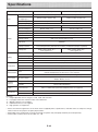
Specifications ................................................................................................................................ E-36
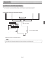
Appendix ........................................................................................................................................ E-37
Connections and Wiring Diagram ............................................................................................... E-37
Meaning of the Terms Used in this Manual
• "The unit" (or "the main unit" or "the product"): Refers to the captureboard.
• USB memory: refers to USB flash memory.
• USB memory storage: means the saving of sheet surface data using MEMORY (i.e., the USB port) of the operation panel.
(The Captureboard has 3 USB ports.)
• Internal memory: indicates a temporary saving location of the image that has been read.
• “copy”: Both “print” and “USB memory saving” mean to “copy.”
• “Sheet surface”: refer to the drawing portion.
• “Scroll” or “move”: indicates feeding of the sheet.
E-3
Important Safety Information
WARNING
WARNING
The unit’s rear panel should never be opened
by anyone other than a qualified serviceperson.
Contact your store of purchase to request internal inspection, adjustment, repair, and cleaning.
This product is not for use in Computer Rooms.
The description “Computer Rooms” refers to
areas where an abundance of computer control
equipment (such as high output servers) is
being used.
It does NOT refer to environments such as
offices or classrooms where there are simply
PC’s being used.
CAUTION
Continued use of the unit under abnormal
conditions (when the unit is emitting smoke,
unusual odors or sounds) could lead to fire or
electric shocks.
Turn off the unit’s power immediately, then
unplug the AC power adapter from the power
outlet.
Check that no more smoke, etc., is being emitted, then contact a sales outlet for repairs.
Repairing the unit yourself is dangerous. Never
attempt to do so.
This symbol warns the user that uninsulated voltage within the unit may have sufficient magnitude
to cause electric shock. Therefore, it is dangerous to make any kind of contact with any part
inside of this unit.
This symbol alerts the user that important literature concerning the operation and maintenance of this unit has been included. Therefore,
it should be read carefully in order to avoid any
problems.
WARNING
SAFETY PRECAUTIONS
This is a class A product. In a domestic environment this product may cause radio interference in which case the user may be required to
take adequate measures.
Heeding the safety precautions below will lengthen the
product’s service life and prevent fires, electric shocks and
injury. Read these safety precautions carefully and be sure
to heed them.
WARNING
Handling the AC power adapter
The Federal Communications Commission
does not allow any modifications or changes
to the unit EXCEPT those specified by PLUS
Vision Corp. in this manual. Failure to comply
with this government regulation could void
your right to operate this equipment.
This equipment has been tested and found
to comply with the limits for a Class A digital
device, pursuant to
Part 15 of the FCC Rules. These limits are
designed to provide reasonable protection
against harmful interference when the equipment is operated in a commercial environment.
This equipment generates, uses, and can radiate radio frequency energy and, if not installed
and used in accordance with the instruction
manual, may cause harmful interference to
radio communications. Operation of this equipment in a residential area is likely to cause
harmful interference in which case the user will
be required to correct the interference at his
own expense.
You are cautioned that changes or modifications not expressly approved by the party
responsible for compliance could void your
authority to operate the equipment.
• Do not connect any AC adapter other than the dedicated one to the unit. Doing so could result in fire or other
accidents.
• Do not use with voltages other than the voltage indicated.
Doing so could result in fire or electric shock.
• Do not let the AC power adapter get wet. Doing so could
result in fire or electric shock.
• Do not subject the AC power adapter to shocks. Doing so
could result in fire or electric shock.
DOC Compliance Notice
This Class A digital apparatus meets all requirements
of the Canadian Interference-Causing Equipment
Regulations.
E-4
Important Safety Information
Handling the AC power adapter’s cord and plug
using it near the shore of the ocean and lakes.
• Do not set the unit in hot places exposed to direct sunlight
or in places exposed to an air conditioner or heating duct.
Do not set the unit in places exposed to soot or humidity
(near humidifiers, etc.).
• When the power plug will be unplugged from the power
outlet, please place the Captureboard near the power outlet so that it may be reached easily.
• Damaging the power cord could lead to fire or electric
shock.
• When installing, do not squeeze the power cord
between the product and a wall, rack, etc.
• Do not modify or damage the power cord.
• Do not place heavy objects on the power cord or pull
strongly on it.
• Do not place the power cord near heating appliances or
otherwise heat it.
• When unplugging the power cord, always do so by pulling on the plug, not the cord.
If the power cord should be damaged, ask your store of
purchase to replace it.
• If there is dust or metal objects on or near the power
plug’s blades, unplug the power cord then wipe the blade
area clean using a dry cloth. Continued use without cleaning the plug could lead to fire or electric shock.
• Do not plug in or unplug the power cord with wet hands.
Doing so could lead to electric shock.
• When moving the unit, turn off the power and be sure to
unplug the power cord from the AC outlet first. Moving
the unit with the power cord plugged in could damage the
cord, leading to fire or electric shock.
• Connect the power plug securely to the AC outlet, pressing the blades in to the hilt. Incomplete plugging could
cause heating or attract dust, leading to fire. In addition,
touching the plug’s blades could cause electric shock.
• Dust or other matter that collects on the accessory outlet
portion could be the cause of fire.
• Do not use a power cord that is in an excessively bent
condition.
Projector
• When using the projector to project an image, and when
making a presentation or the like, light from the projector
may enter the eye.
Direct viewing of the projector light will be a cause of injury
to the eye; therefore, due caution should be taken.
Preventing Tipping (for stand type units)
To prevent tipping, heed the instructions below. Tipping
could lead to personal injury or damage the unit.
• Use the unit on a flat floor.
• Be sure to attach the supplied stabilizers to the stand, and
lock the stoppers of the casters. Failing to do so could
result in the unit tipping and could lead to personal injury.
• Do not lean against the unit or apply excess force to the
top of the unit.
Cautions on Usage
• Take care that the unit does not get wet and that water
does not get inside. Do not place objects containing chemicals, water or other liquids (vases, potted plants, glasses,
cosmetics, etc.) on top of the unit. The liquid could spill
and get inside the unit, leading to fire or electric shock.
• When lifting the unit to adjust the height, etc., the unit
should be lifted by at least two persons to prevent it from
tipping and causing personal injury.
• Do not move the sheet with paper or other objects
attached to it. Doing so could cause damage.
• Do not wipe the unit or sheet with thinner, benzene, alcohol or other such products. Doing so could cause discoloration or damage the sheet.
• Please be sure to use the dedicated markers and erasers. Use of other types of markers or erasers, or rubbing
directly with the hand may scratch the sheet, or may soil
the sheet and the ink may not come off.
The markers must be stored in a horizontal orientation.
The ink may be difficult to remove if they are not.
• When moving the (stand type) unit, remove the stabilizers
and release the caster locks. Hold the sides of the main
unit and move it gently. Avoid shocks.
• When not using for long periods of time, for safety be sure
to unplug the AC power adapter from the power outlet.
• Make entries within the effective reading size. (See page
E-9) Portions that are drawn outside of this range might
not be printed or copied when saving to USB memory or
personal computer.
• Just as with the Captureboards up until now, please do
not move the sheet manually (by hand) with the current
model. Doing so may result in improper storage or printing
of the information drawn on the sheet surface.
Handling the included AC adapter box
• An AC adapter box is provided with the Captureboard for
storing the AC power adapters of the Captureboard and
printer.
The AC power adapters and the power cords generate
heat. Place them sufficiently apart and do not bundle the
cables together, or the adapters and cables could heat up,
leading to fire.
• Do not place vases, potted plants, glasses, cosmetics or
containers of chemicals or water on the printer table. The
liquid could spill and get into the AC adapter box, leading
to fire or electric shock.
Do not use the included CD-ROM in a player
designed for audio CDs.
• Never use the included CD-ROM in a player designed for
audio CDs. Doing so could produce loud noises that could
impair your hearing. These noises can also damage your
speakers.
Installation
• Only a specially trained technician should install the set.
Improper installation could lead to injury.
• When mounting on a wall, be sure to check first that the
wall surface is strong enough to support the total weight of
the main unit, mount fittings and printer for a long period
of time (including during earthquakes). If the wall is not
strong enough, reinforce it before mounting the unit.
• Getting water on or inside the unit etc., could lead to fire
or electric shock. Be particularly careful when using the
unit near a window when it is raining or snowing and when
E-5
Important Safety Information
Cleaning
• Note that copying illegal material (tantamount to possession of illegal material) is subject to prosecution.
• If the sheet is dirty, wipe it off with a damp, thoroughly
wrung cloth. For tough dirt, use the included cleaning
cloth.
• Do not wipe the Captureboard or sheet with thinner, benzene, alcohol, etc. Doing so could cause discoloration or
damage the sheet.
• Wipe of any marks from markers on the pen tray or the
frame cover using a damp, thoroughly wrung out cloth.
• When the erasing surface of an eraser has become soiled,
exchange the sponge with a spare one, and then use.
Using a soiled eraser will soil the sheet surface, and it will
be difficult to remove the soiled matter from the sheet.
• This product includes parts considered as “strategic
material” as per the Foreign Exchange and Foreign
Trade Control Act of Japan. Authorization as per said
Act is required to export this product from Japan.
Handling the CD-ROM
• Do not touch the surface which has no printing (the surface on which the data is recorded). If this surface is dirty
the data will not be read properly.
Also, do not stick paper, stickers, etc., on the CD-ROM.
• Do not leave for long periods of time in places exposed to
direct sunlight or near heating appliances, and do not drop
or bend the CD-ROM. The disc may get warped, making it
impossible to read the data.
USB Memory
• The USB memory formats supported by the Captureboard
are FAT, and FAT 32. There are also types of USB memory that cannot be used by this unit. Check the PLUS Vision
web site for types of USB memory that have been verified
to work with the Captureboard.
• As a provision against the unlikely event of a problem with
or disappearance of the data saved in the USB memory,
we recommend that the data be regularly saved to other
media.
• PLUS Vision will not be responsible for the loss of content
stored in the internal memory of this unit (i.e., images that
have been read), or in USB memory.
USB Cables
When using a USB cable other than the one supplied with
the Captureboard, use a USB shielded cable bearing the
USB-IF logo certification. Do not use the Captureboard connected to a USB hub. Improper operation may result.
E-6
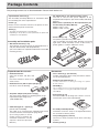
Package Contents
The package contents are as described below. Please check before use.
Captureboard, main unit [1]
See “Assembly and Setup Manual” for information about
the assembly parts of the Captureboard.
Printer* [1]
Please see the instruction manual of the printer for information about the printer accessories.
Stand* [1]
• AC adapter box (1 unit, with 2 masking screws)
Use this to store the AC power adapters of the
Captureboard and printer. (See the Assembly and Setup
Manual.)
• Cable covers specifically for the Captureboard (see
the Assembly and Setup Manual)
Model C-12S: 1 cover
Model C-12W: 2 covers
* The printer and stand may be sold separately.
* Depending on the product you have purchased, the printer and
stand may be sold separately.
Assembly and installation parts
• Wall mount brackets [1 set]
These fittings are used to mount the Captureboard on a
wall (See the Assembly and Setup Manual.).
(The set includes four Captureboard brackets and 16 M4
mounting screws.)
• Printer table [1 set]
The printer is placed on this printer table.
(The set includes one printer table, brackets for left and
right sides, 10 M3 assembly screws, 4 M4 screws, 2
printer guides, 2 cushions and Velcro 2 sets)
Captureboard Accessories
Documents
• Dedicated markers
(One each of black, red, blue, and
green)
Use these markers to draw on the
sheet surface.
• User’s manual [1] (this manual)
Includes information about safety precautions and the
use of the Captureboard.
• Software Operation Manual ... 1
Includes information on setting and using the captureboard software.
• Dedicated eraser (with 2 spare sponges) [1]
Use this to erase the drawing.
• CD-ROM [1]
This includes the user's manual (in PDF format) and
special software for using the Captureboard (PLUS
TOOLBOX).
• AC power adapter (with power cord) [1]
This is the power adapter for supplying power to the
Captureboard (See Page E-13).
(HEC-AP065-24V)
• Quick Guide [1 set]
The Quick Guide can be hung from a hook in a convenient location close to the Captureboard.
• USB cable (type B ↔ type A) [1]
[PLUS code 715255400]
This cable is for connecting the Captureboard's Printer
connector with the exclusive printer (page E-13).
(If not using a printer, it can be
used to connect a computer. For
connection instructions, see the
separate "Software Operation
Manual".)
E-7
• Assembly and Setup Manual
Information covers the setup of the Captureboard and
the connections with the printer.
• Test printing paper (5 sheets)
Use these to make connection tests when connecting
a printer.
• Cleaning cloth (1)
Main Functions
Allows the projection of an image that is easy on the eyes, and the use of the dedicated
markers and eraser permits direct writing and erasure on the screen sheet surface.
Use of a special screen sheet allows for the projection of an image with the glare of the sheet surface due to the
light of the projector being suppressed to the utmost. The use of the dedicated markers and eraser permits direct
writing and erasure on the screen sheet surface. Being able to use one piece of equipment as both a Captureboard
and a projector screen permits effective use of the setup space, and saves the trouble of separate preparation.
The projection image of the projector and the handwritten information on the Captureboard
are captured on the personal computer, and stored as a superimposed image file.
Use a USB cable to connect the Captureboard to the projector and the connected personal computer. The installation of dedicated software combined with performing simple operations permits the projected image of the projector
and the handwritten information that has been written on top of it to be captured on the personal computer, superimposed, and saved. Meeting updates, and important information can be conveyed to associates realistically just as it
is written and just as it appears.
Text or images drawn on the Captureboard’s sheet surface can be loaded directly onto a
computer as image files.
When a USB memory device is inserted into the bottom of the control panel and the "Save" button on the control
panel is pressed, the data drawn by hand on the sheet surface is stored on the USB memory device as an image file
(in either PNG, JPEG or PDF format, selectable).
Maintenance-free, Low Power Consumption
RGB, 3-primary-color LEDs are used as the reading light source which means that there is no need to replace a
fluorescent tube as with previous Captureboard models. In addition, unlike fluorescent tubes, LEDs need only be lit
when reading the sheet surface which is reflected in low power consumption.
Erase Reminder function
When turning off the power, if there is a page (sheet surface) you have forgotten to erase, the sheet automatically
moves to the surface that is not yet erased and the power turns off.
Header/footer function
The included software can be used to insert text (titles, the company name, the date, etc.) or images in the margins
at the top and bottom of the page and print or store the same data each time.
E-8
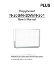
Names of the Parts
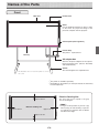
Front
Main unit
Frame cover
Sheet
Use the dedicated markers to draw or write
on the sheet. Or, project the image of the
personal computer with the projector.
Control panel (See Page E-12)
Printer table
The printer*1 is placed here.
Pen tray
AC adapter box
Store the AC power adapters of the captureboard and printer here. (See the Assembly
and Setup Manual.)
Stand*2
This stand supports the Captureboard.
* This illustration does not show the printer or connection cords.
*1 The printer is available separately.
*2 Depending on the product you have purchased, the stand may
be sold separately.
Effective Reading Size
approx. 10 mm
The area that can be copied is the gray
area of the diagram.
Note
Effective reading size
approx. 10 mm
approx. 10 mm
approx. 10 mm
E-9
• It might not be possible to print or copy
when storing to USB memory or personal computer any portions that are drawn
outside of this range.
Names of the Parts
Rear
DC input connector
Connect this with the DC plug end of the AC
power adapter. (See Page E-37.) (Only connect
the supplied AC power adapter; nothing else.)
P
R
IN
TE
R
P
C
Personal computer (PC) dedicated USB port
(Type B)
Connect this with the USB port (type A) of the
PC. (See Page E-37.)
Special software can be used to transfer
image data directly to the computer and set
the captureboard's operating environment. To
use these functions, first install the drivers and
software on the included CD-ROM onto the
computer. (See the separate software operation
manual.)
Printer connector (USB port Type A)
Connect this with the USB connector of the
printer (See Page E-37).
(The printer connector is dedicated for use with
a printer; use it only with a printer.)
The connector is located on the bottom surface of the main unit. The diagram view is
seen from the bottom.
* This illustration does not show the printer or connection cords.
Locking and unlocking the casters of the stand
Lock the casters with the stopper after setup. To move the unit,
remove the stabilizers and release the caster stopper.
Press the bottom of the stopper to lock it. Press the top to
release it.
Unlock
Lock
Stabilizer
E-10
Caster
Names of the Parts
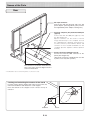
Changing the Height of the Unit
This is the height adjustment when setting up the Captureboard on the optional stand. The stand height can be
adjusted to 3 levels by 100 mm.
CAUTION
• Please have 2 or more persons lift the Captureboard when installing it or making a height adjustment.
If the unit is dropped or falls over, this could cause unforeseen injury.
• When a printer is mounted on the captureboard, remove the printer before performing this procedure. Failure to do
so could result in injury due to unexpected falling or tipping.
• Unplug the power plug from the wall power outlet and remove the power cord from the stand's cable cover before
performing this procedure. Failure to do so could result in injury due to the stand tipping over unexpectedly.
Please lock the casters by pressing the lower portion of the lock buttons of them.
(1) Unplug the AC power adapter's power plug from the wall power outlet and remove the power
cord from the stand's cable cover.
(2) Remove the printer from the printer table.
Disconnect the USB plug from the printer and the DC power plug, loosen the printer guide's fixing screws and remove
the printer.
(3) Remove the two locking screws (located at the left and right sides).
(4) Change the hole position of the Captureboard rear frame.
The Captureboard will disengage from the hooks when it is lifted up about 1 cm.
Fully hook the (2 left and right) installation holes of the main unit rear frame onto the hooks of the stand.
If a stay (for preventing shaking) is mounted on the printer table, insert the stay in its original position.
(5) Attach the locking screws to the 2 locations (left and right)
and tighten to the rear frames.
(6) Return to original by following the steps in reverse.
Mounting hole
Rear frames
Hook
lock-screw
Stand
Cable cover specifically for the stand
*The printer may be an option.
* Appearance of printer is for illustration purposes.
E-11
Names of the Parts
Control Panel
When pressing a button, please press the center area (i.e., the round and protruding portion). The button may
not work if it is pressed on a corner.
2
Display window
Displays the connection status between the
Captureboard and the computer, the operational status
of USB memory storage, and error information on a 7segment LED.
“PC” is displayed when the Captureboard is connected
with a personal computer. Note that “OP” is displayed
when the Captureboard is not connected with a personal computer. Please see Page E-32 for details about
error information.
3
Save
button (USB memory storage)
Moves a one-screen portion of sheet and reads it, then
stores the data on a USB memory.
4
Memory
port (USB port Type A)
Saves in commercially-available USB memory images
that have been read by the Captureboard.
5
Feed
button
Scrolls the sheet one screen portion left, then stops
automatically.
6
+ / − buttons (Time Setting)
Press the + button or the − button and perform the setting of the date/time. See Page E-14 for details.
7
Print
button
Moves the sheet one screen portion and reads it, and
prints the image.
* Used only when there is a printer connection.
8
Reprint
button
Prints the previously printed sheet surface one more
time. (The sheet does not move.)
The density and the color/monochrome selection cannot
be changed.
* Used only when there is a printer connection.
9
1
ON/Standby
button
Selects the copying density, either “standard” or “dark”.
This function will be effective at time of printing, USB
memory storage, and personal computer storage.
button
Turns the Captureboard’s power on and off (standby
mode).
The function settings can be made by pressing the
Density
and ON/Standby
buttons simultaneously.
For details, see page E-28.
Note
Density
Density mode lamp
When “dark” is selected, the density mode display indicator will light green. This is enabled during USB memory storage, personal computer storage, or printing.
10 Color
button
Selects whether to store in memory (or print) in “color”
or “black & white”.
If the Erase Reminder function has been set, the
sheet moves to the surface that has not yet been
erased before the power turns off *1.
*1 Depending on the usage method, the Erase
Reminder function may not operate properly.
Color mode lamp
The indicator lights green when “color” is selected.
* In accordance with the printer function when a printer
is connected.
E-12
Connecting the Power
Note
About the connection and the AC adapter box
The AC power adapters of the captureboard and printer are stored in the AC adapter box.
In this manual, "AC power plug" refers to the AC power plug of either the captureboard or the printer.
If the AC power adapter is not connected or placed in the AC adapter box, see the separate " Assembly and Setup
Manual " and connect according to the purpose
Wall outlet
AC adaptor box
Printer's AC power
adapter
Copyboard's AC power adapter
To use the captureboard, connect the captureboard's AC power plug to a wall power outlet.
The main power turns on. In this manual, this is referred to as the “standby mode”.
The descriptions in this manual assume that the AC power plug is connected (that the unit is in the standby mode).
To use the printer, also connect the printer's AC power plug to a wall power outlet.
Before printing, turn on the printer's power.
When not using the captureboard for long periods of time
Disconnect the AC power adapter’s power plug from the AC power outlet in the wall.
Notice
• When the AC power adapter’s power plug is unplugged from the power outlet, place the captureboard near the power
outlet so that it can be reached easily.
• The supplied AC power adapter and AC power cord are intended for exclusive use with this product. Never use them
with another product.
E-13
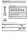
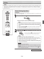
Setting the Time
Set the captureboard's clock properly. The date and time are printed in the header/footer when printing and
recorded in the file data when saving the file.
Overview of the Operation
1
Switch to “Time setting”
Press the + or – button.
2
Display the day and hour setting mode
Setting mode information indicated in the display window
(First 2 digits)
(Last 2 digits)
Year
3
Month
Day
Hour
Minute
Set the date and time of the setting mode
One press of the + or the − button will enable the settings to be made.
Press the + or − button and make the adjustment.
4
Press the Print
button to confirm
There is a change to the next setting mode.
Repeat steps 3 and 4 to set the current time.
5
Completion
To quit the time setting mode, press the Print
button.
• Pressing the ON/Standby
button during operations 2 to 4 will cancel the
incomplete settings and return to the time prior to starting the settings.
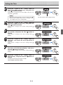
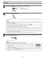
Preparation: Connect the captureboard's AC power plug to a wall power outlet. E-13
Example: Set the time to 2:16 pm, November 8, 2008 (2008.11.08 14:16).
Press the ON/Standby
the power.
button to switch on
The LED of the display window will light and the power will
be switched on.
Press the + or – button and change to “Time
Setting”
The LED of the display window will light and display “
”.
E-14
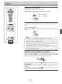
Setting the Time
Press the + button or the − button, select 20
(the first 2 digits of the year), and press the
button to finalize.
Print
There will be a change to the “last 2 digits of the year” setting mode (
display).
Note
• The factory default setting is 20. Pressing the Print
button in this condition will result in a change to the
“last 2 digits of the year” setting mode.
Press the + button or the − button, select 08
(the last 2 digits of the year), and press the
button to finalize.
Print
There will be a change to the “month” setting mode (
display).
Press the + button or the − button, select 11
button to
(the month), and press the Print
finalize.
There will be a change to the “day” setting mode (
display).
Press the + button or the − button, select 08
button to
(the day), and press the Print
finalize.
There will be a change to the “hour” setting mode (
display).
Press the + button or the − button, select 14
(the hour of the 24-hour display), and press
button to finalize.
the Print
There will be a change to the “minute” setting mode (
display).
Press the + button or the − button, select 16
button to
(the minutes), and press the Print
finalize.
The display will change to being lit steadily.
This completes the time setting.
E-15
The dot will flash while making settings.
Operation Steps
When used as a Captureboard
The Captureboard uses a CCD image sensor to read the text and drawings that have been written down with
dedicated (4-color) markers, and accumulates the image data in internal memory.
The "TOOLBOX" software on the included CD-ROM can be used to combine the image of the projector projected onto the sheet surface with the words or diagrams drawn on the sheet surface.
Preparation
• Set up the newly purchased Captureboard and connect a printer.
See a separate manual titled “Assembly and Setup Manual.”
• Plug the AC power plugs of the captureboard and printer into wall power outlets. See page E-13.
• Set the time of the newly purchased Captureboard. See Page E-14.
Write and Draw on the Sheet Surface
Please use the supplied dedicated markers for drawing. To erase something, erase it with the supplied dedicated eraser.
Please be sure to use the dedicated markers and erasers. Using other markers or erasers may
result in the markings not coming off, or may stain the sheet.
When combining the sheet surface drawing with a projector image
(1) Connect the computer on which "PLUS TOOLBOX"
is installed to the captureboard.
(2) Project the image of the personal computer with
the projector.
(3) Adjust the projected image for a suitable size.
(4) Use the supplied dedicated marker to draw a circle
“o” at the four corners of the projection image.
(5) The image of the sheet screen will be read. Check
that there is a combined image on the computer
screen.
(6) Save the combined image on the personal
computer.
Note
• For details on operating PLUS TOOLBOX and on
connecting devices, refer to the separate " Software
Operation Manual".
When Not Using the Captureboard
(1) By all means, cleanly erase the drawing from the sheet surface with the dedicated eraser. (Leaving the drawing for a
long period will make it harder to erase.)
(2) When disconnecting the USB cable of the Captureboard and personal computer, first disconnect the USB at the personal computer side.
(3) Press the ON/Standby
button of the Captureboard and switch off the power (standby mode).
E-16
Operation Steps
When used as a Copyboard
Pressing the Print
button outputs the content drawn on the sheet surface from the printer, and pressing the
Save
button stores the information in the USB memory as image data.
Printing
Saving to USB Memory
(1) Set A4 or letter size paper.
Do not set anything other than
A4 or letter size paper.
(2) P r e s s t h e O N / S t a n d b y
button of the
Captureboard and switch on the power.
(3) Switch on the printer power.
For instructions on operating the printer, see the
printer’s operating instructions.
(4) Press the Print
button. The Captureboard will
move a one-screen portion of sheet, read the
image, and start the copy operation*.
See “Printing” on Page E-18.
(1) Press the ON/Standby
button
of the Captureboard to switch on
the power.
(2) Insert USB memory into the Memory
port
(USB port) of the Captureboard.
(3) Press the Save
button.
See “Using USB Memory” on Page E-23.
* Images projected with a projector cannot be saved in
USB memory.
* Images projected with a projector cannot be printed.
When Not Using the Captureboard
(1) By all means, cleanly erase the drawing from the sheet surface with the dedicated eraser. (Leaving the drawing for a
long period will make it harder to erase.)
(2) Press the ON/Standby
button of the Captureboard and switch off the power (standby mode).
The power cannot be switched off while the USB memory remains installed. (This is a prevention function against
forgetting to unplug the USB memory.)
The captureboard is equipped with an Erase Reminder function for the back side of the sheet. By factory default this
function is disabled. It can be turned on by either by changing the function settings (see page E-28) or by setting
"Enable" at "Erase Reminder" in TOOLBOX. (For instructions on operating TOOLBOX, see the separate "Software
Operation Manual".)
(3) Switch off the printer power.
button to perform the read operation. Pressing the Save
button during printing will store the information
* Press the Print
in the USB memory after printing is completed. Press the Save
button to perform the read operation. Pressing the Print
button while storing the information in the USB memory will start the printing operation after storage is completed. This
allows both printing and USB memory storage to be performed in a single reading operation.
Note
• When turning on the power, wait about 5 seconds after connecting the captureboard's AC power plug to the wall
power outlet or after turning off the power (standby mode) before pressing the ON/Standby
button.
• The color of the images when printed in color or when saved in USB memory will differ somewhat from the marker
colors.
• Blurred characters, thin lines, overlapping of markers and other factors can cause colors to differ in places and can
also result in portions that cannot be scanned successfully. When “Density” is set to “Dark”, the overall print may be
dark.
In the case of the combination of Dark and Color Mode, the black ink may be mixed into other color.
• The built-in memory accumulates the read data that was previously printed or stored in USB memory. This data is
erased when the power is switched off with the ON/Standby
button.
E-17
Printing
Use a printer to print out the text and drawings that has been drawn on the sheet surface.
Operations and names of parts differ from printer to printer. For details of operations, see your printer’s operating
instructions.
Notice
Images projected with a projector cannot be printed.
Preparing the Printer
Please check that the Captureboard and the printer have been connected. See Page E-37.
Set the paper.
Please use A4 or letter size printer paper.
See your printer instruction manual for details.
1) Arrange the paper edges so that they are even.
2) Insert paper at the specified position of the paper tray.
3) Press the paper guide gently until it touches the paper.
Paper guide
* Appearance of printer is
for illustration purposes.
Note
See your printer’s operating instructions for a
description of the paper that can be used.
Paper
Switch on the power.
Press the power switch. The power indicator lights.
This completes the preparation of the printer.
Press the Print
button on the Captureboard’s control panel. One
page worth of data is read and the printing operation starts.
Notice
Paper guide
Power switch
Paper tray
• Depending on the printer, indicators, etc., may flash after the
power is turned until the printer is prepared to print. In this
case, see the printer’s operating instructions and check that
the printer is ready before starting the printing operation on the
Captureboard.
When finished printing...
Switch off the printer power and remove the paper.
Close the paper tray.
Notice
Do not turn off the power or disconnect the USB cable during
printing.
E-18
Printing
Note
• Text (titles, the company name, the date, etc.) or images can be inserted in the margins at the top and bottom of the
pages and the same information printed on all pages. The information at the top of the page is called the header, the
information at the bottom the footer. For instructions on creating headers and footers, see the separate "Software
Operation Manual".
Basic Printing Operation
Preparation:
Check that the AC power plugs of the captureboard and printer are connected to wall
power outlets. See Page E-13.
Press the ON/Standby
button and switch on the power.
Prepare the printer. (See the previous page.)
Note
• When turning on the power, wait about 5 seconds after connecting the
captureboard's AC power plug to the wall power outlet or after turning off the power (standby mode) before pressing the ON/Standby
button.
• Press the ON/Standby
button to switch on the power. The LED of the
display window will light.
• Turn on the Captureboard power before turning on the printer power.
Press the Feed
want to print.
button and display the sheet surface you
A press of the Feed
button scrolls the sheet surface
one screen portion left and automatically stops it.
Note
• The one-screen that is visible is printable position.
• The image that is projected onto the sheet surface will not be printed.
• Printing of the portion located around the sheet surface might not be
possible. Please see “Effective reading size” on Page E-9.
• When the stop position of the sheet is shifted, after the visible screen
has been scrolled, the screen is further scrolled to the correct stop position and stops automatically.
Notice
• Do not move the sheet manually.
When the stop position of the sheet is offset, the drawing may not print
properly.
• When the stop position of the sheet is shifted, press the Feed
button
and set the proper stop position.
Continued on next page
E-19
Printing
Press the Color
button and select Color or Black & White.
Color mode lamp
Lit
Printing will be in color.
Unlit
Printing will be in black & white.
Press the Print
button to print.
• The reading operation is performed for a one-sheet portion (while the sheet is scrolled) and the printing operation is
performed.
Note
button is pressed while the sheet surface is being read, printing is interrupted and only
• If the ON/Standby
part of the image will be printed.
To move the sheet surface, wait until scrolling stops, then press the Feed
button.
• When a USB memory has been inserted, a press of the Save
button during printing will start the USB memory storage operation after printing is completed. (See Page E-23.)
• The one-screen portion is reduced to A4 paper size and printed.
For wide type Captureboards (model C-12W), the image is compressed about 75% in the horizontal direction. To print
with the same proportions as the image on the sheet surface, see “Printing in the same ratio as the sheet surface” (page
E-22).
• A flashing “ ” in the display window indicates a print error. See “Meaning of Error Messages” on Page E-32.
• While scrolling, a moving hole will be visible at the bottom of the sheet; however, this is a required hole according to the specifications and is not damage.
• When the sheet is moving, buckling of the sheet may be observed; however, this is not a fault.
When the Captureboard is not going to be used, press the ON/Standby
off the power (standby mode).
button and switch
• Switch off the printer power.
Note
• When the Erase Reminder function is set to "Enable"
When the ON/Standby button is pressed, the display window and all the indicators flash
simultaneously, the sheet automatically moves to the surface that is not yet erased and
the power turns off.
* The Erase Reminder function may not work properly due to dirt on the sheet's adhesive
Display window
sections or marker residue.
• If no button is operated for 30 minutes or greater, the unit is set to the sleep mode and the LEDs on the control
panel turn off. If the ON/Standby
button is pressed, the LEDs on the display window turn on. If the print button
is pressed at this time, the printing operation starts.
E-20
Printing
Selecting the printing density
Select this when the density of the print is light.
Press the Density
button and select darker or standard.
Density mode lamp
Lit
Darker
Unlit
Standard
Making additional copies
This will print the copy of the sheet that was scrolled previously one more
time.
Press the Reprint
button.
This starts the printing of the image data that has accumulated in internal
memory.
Note
• The sheet is not scrolled when additional copies are made.
• In repeat printing, the color/black & white and density settings will be
the same as those of the prior printing.
• When printing or USB memory storage has not been performed since
switching on the power, image data will not have accumulated in the
internal memory and this operation will not be possible.
• If additional printing is set to "Disable" in the security function settings, display number "E8" is displayed. For details, see the separate
"Software Operation Manual".
Cancellation of the print operation in progress
During the read operation (when the Print
button was pressed)
button is pressed, the reading of the sheet stops,
When the ON/Standby
the Captureboard returns to the original page and the partially read image
data is printed. Wait until the sheet is expelled from the printer.
Stopping the printing after the Print
button was pressed and the reading completed
Stopping during reprinting (When the Reprint
button has been
pressed)
Press the Captureboard’s ON/Standby
button. After several seconds, printing is interrupted and the sheet is expelled.
E-21
Printing
Printing in the same ratio as the sheet surface (Model C-12W)
Model C-12W is the wide type Captureboard which will compress printing in the horizontal direction resulting in crowded printing of the A4 or LETTER size sheet; for example, a circle will become an ellipse. To print in the same aspect ratio as a drawn
diagram, the compression mode will be changed (to suit the paper size according to the sheet surface image). The factory
default setting is the horizontal compression mode.
Check that the power is turned on (that the display window is lit).
1.
button, press the
While pressing in the Density
button to switch to the function
ON/Standby
settings mode.
"F1" appears on the display window.
2.
Press the + or – button (the display switches each
time one of the buttons is pressed) to display "F4",
then press the Save button to finalize.
Forward / Reverse
When "F4" is displayed, the captureboard is in the printing ratio
setting mode.
3.
Press the Feed
mode.
button to select the equal ratio
Lamps when the captureboard is set to condense
the image in the horizontal direction:
Color mode lamp: Off
Density mode lamp: Lit
Lamps when the captureboard is set to print in
equal ratio:
Color mode lamp: Lit
Density mode lamp: Off
Check that the lamps are lit or off as indicated at " Lamps when the captureboard is set to
print in equal ratio" above, then press the Save
button to finalize. The dot next to the
"F4" dot flashes for several seconds.
• To restore the captureboard to print with the image condensed in the horizontal
direction, switch the mode so that the lamps are as indicated at "Lamps when the
captureboard is set to condense the image in the horizontal direction", then press
the Save
button.
This completes the setting. Press the ON/Standby
button to return to the normal mode.
E-22
Dot flashes for several
seconds
Using USB Memory
The content of what has been drawn on the sheet surface of the captureboard can be saved in USB memory.
Later, the saved image can be read into a personal computer and made into a document of the proceedings of
the meeting, or affixed to a document.
• What is needed to use the USB memory function
USB memory: Commercially-available product
Personal computer: The connector is a USB port (type A), and the interface supports USB 1.1
Note
• The captureboard supports the USB memory formats of FAT and FAT 32.
• The factory default for the resolution of images when storing them on USB memory devices is "Standard". There
are two ways to switch this to a high resolution: by changing the captureboard's function Settings (see page E28), or by setting "Resolution" in TOOLBOX to "High Resolution". (For instructions on operating TOOLBOX, see
the separate "Software Operation Manual".)
• More time is required for storing images when the resolution is set to high.
Notice
• Images projected with a projector cannot be saved in USB memory.
• For the specification of the USB memory devices compatible with this Captureboard, please go to our website at:
http://www.plus-vision.com
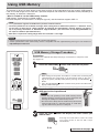
USB Memory Storage Procedure
Preparation:
Check that the captureboard's AC power plug is connected to a wall power outlet.
See page E-15.
Press the ON/Standby
button and switch on the power.
Note
• When turning on the power, wait about 5 seconds after connecting the
captureboard's AC power plug to the wall power outlet or after turning off the power (standby mode) before pressing the ON/Standby
button.
• Press the ON/Standby
button to switch on the power. The LED of the
display window will light.
Insert the USB memory device into the Memory
(USB port) of the Captureboard
Notice
port
/ y
Ndb
On
ta Y
S R
M
E
O
M
• Check the side (polarity) of the USB memory device
before inserting it. Forcing it in the reverse orientation will
damage the USB port or USB memory device.
• Be careful not to bump into the USB memory device with
hand or body while it is mounted. Doing so could damage the USB memory device or USB port.
Press the Feed
want to store.
button and display the sheet surface you
Pressing the Feed button scrolls the sheet
one screen portion to the left and it stops
automatically.
E-23
Continued on next page
Using USB Memory
Step 3 (continued)
Note
• The one screen portion that is viewable will be saved in USB memory.
• Saving of the portion located around the sheet surface might not be possible. Please see “Effective reading
size” on Page E-9.
• When the stop position of the sheet is shifted, after the visible screen has been scrolled, the screen is further
scrolled to the correct stop position and stops automatically.
Notice
• Do not move the sheet manually.
When the stop position of the sheet is offset, the drawing may not save properly.
• When the stop position of the sheet is shifted, press the Feed
button and set the proper stop position.
Press the Color
button and select Color or Black & White.
Color mode lamp
Lit
Printing will be in color.
Unlit
Printing will be in black & white.
Press the Save
button to store
Flashing indicator “rotates” sequentially during USB memory storage operation.
Display window
• The reading operation is performed for a one-sheet portion (while the sheet is scrolled) and USB memory storage
starts after the scrolling completes.
The (5 second) flashing “US” display indicates that the USB memory has not been inserted. Please
insert the USB memory and then press the Save
button.
A (5 second) flashing “FL” display indicates that there is insufficient free capacity to permit storage
in USB memory. The flashing display will stop when the USB memory device is removed. Replace
with a USB memory device having sufficient capacity.
See “Meaning of Error Messages” on Page E-32 for other error displays.
Note
• Depending on the USB memory, it may take time for recognition or it may take time for saving.
button is pressed during the reading operation, the reading operation will be discon• When the ON/Standby
tinued and the partially read image data will be stored in the USB memory.
To move the sheet surface, press the Feed
button after the scrolling has stopped.
• The image that is projected onto the sheet surface will not be saved to USB memory.
• A press of the Print
button during USB memory storage starts the printing after storage is completed.
• When the wide type (C-12W) Captureboard has been adjusted to the paper size in the horizontal direction, the
image will be compressed to about 75%.
• The date and time of the saved file will reflect the Captureboard time setting. See “Setting the Time” on Page
E-14.
• When a certain amount of free capacity is not available in the USB memory, “FL” will be displayed when the
Save
button is pressed. Also, when insufficient free capacity arises during saving, “FL” will be displayed at
that time. Delete the data and return the sheet surface to the original condition, then press the Save
button
again.
E-24
Using USB Memory
Removing the USB memory
Check that the flashing rotation of the display window has changed to steady lighting
and that the USB memory access indicator is not flashing, then pull the USB memory
straight out. (Please see your USB memory manual for details.)
/ y
Ndb
On
ta Y
S
M
E
R
O
M
Notice
• Do not unplug the USB memory device during the USB memory storage operation (i.e., during the rotating, flashing display in the display window), or while
the access indicator of the USB memory device is flashing because data will be
destroyed.
When the Captureboard is not going to be used, press the ON/Standby
off the power (standby mode).
button and switch
Note
• When the Erase Reminder function is set to "Enable"
When the ON/Standby button is pressed, the display window and all the indicators flash
simultaneously, the sheet automatically moves to the surface that is not yet erased and
the power turns off.
* The Erase Reminder function may not work properly due to dirt on the sheet's adhesive Display window
sections or marker residue.
” letters appearing at one-second intervals in a moving display in the display window indicate that a USB
• “
memory device is mounted. Unplugging the USB memory device will switch off the power. (A function that
serves as a reminder to unplug the USB memory device)
• If no button is operated for 30 minutes or greater, the unit is set to the sleep mode and the LEDs on the control
panel turn off. If the ON/Standby
button is pressed, the LEDs on the display window turn on. If the save buttonis pressed at this time, storing of the data in the USB memory device starts.
E-25
Using USB Memory
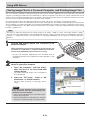
Saving Image Files to a Personal Computer, and Deleting Image Files
This is an operation example of storing the image file that has been stored in USB memory on the hard disk of the personal
computer, or deleting the folder when the USB memory capacity has become full. (There are various methods that can be
used for saving and deleting including the use of Explorer.) See the instruction manual of your personal computer or the software that you are using for information about using a personal computer.
The captureboard's folder on the USB memory device is named "CB_image". The images are stored in this folder.
By factory default set when the captureboard is purchased, the image files are named "PV-xxxxxxxx.png" (in PNG format),
where "xxxxxxxx" is the date and number (for example (PV-08110801.png). The date is the date of shipment from the factory
(in Japan Standard Time). If this differs from the current time in your location, change the captureboard's time. (See "Setting
the Time" on page E-14.)
Note
The format in which the image files are stored can be set to "PNG", "JPEG" or "PDF". The factory default is "PNG".
This format can be changed either in the captureboard's function settings (see page E-28) or in TOOLBOX at "Function
Settings" -> "Image File Format". (For instructions on operating TOOLBOX, see the separate "Software Operation
Manual".)
Plug the USB memory device into a USB port of the
personal computer
When connecting to the personal computer for the first time, the
installation of a USB driver is required. Follow the instructions
manual of the USB memory device that you are using.
• Usually, with Windows 2000/XP/Vista the standard driver is
installed automatically and is identified as “Removable disk” in “My
Computer.”
Saving the image files of a USB memory
device to a personal computer
1. Open “My Computer” and from within,
open the drive of the connected USB
memory device.
The folder named “CB_image” is the saved data of
the Captureboard.
2. Store the “CB_image” folder in “My
Documents” or another location.
All of the data contained in “CB_image” will be
stored.
Drag to My Documents
Notice
Depending on the computer’s usage environment,
these operations may not work properly. This
could be the case for example:
• when several USB devices are connected simultaneously to the computer.
• when the USB device is connected to a USB hub
or when it is connected using an extension cable.
E-26
Using USB Memory
Deleting USB memory image files with the
computer
Before deleting important image files, be sure to save them
on the computer (as a data backup).
1. Open “My Computer” and then open the
drive icon which shows USB memory.
The folder named “CB_image” contains the memory storage data of the Captureboard.
2. Place the “CB_image” folder in the “Recycle
Bin”, right click on the icon and select
“Empty Recycle Bin” from the pull-down
menu.
All of the data contained in “CB_image” will be deleted.
Even when the entire folder is deleted, a new “CB_image”
folder will be created automatically when USB memory is
used again with the Captureboard.
Drag to the Recycle Bin
Disconnect the USB memory
The disconnecting procedure depends on the computer’s operating system. For details, refer to the computer’s operating
instructions or help files.
1. Click the [Hardware Removal] icon that is
displayed in the task tray.
Click “Stop USB Mass storage Device - drive (E)”. (The E
drive character will differ depending on the personal computer system.)
“Remove hardware” icon (example)
2. Click [OK] when “The ‘USB Mass storage
Device’ device can now be safely removed
from the System” is displayed.
(When using Windows XP/Vista, [OK] does not appear on
the message screen. Simply disconnect. )
3. This allows the USB memory device to be
unplugged from the computer.
Note
• Do not disconnect the USB memory device while the
USB memory device’s access indicator is flashing. Doing
so will damage the data.
• The USB drive may not be disconnected properly, for
example if the computer is in the process of checking the
status of peripherals.
E-27
Making the Function Settings
The captureboard includes such advanced functions as the Erase Reminder function that can be set directly
using the operation buttons on the captureboard. The advanced functions can also be set from the function
settings in the "TOOLBOX" menu installed on a computer (See the separate "Software Operation Manual".)
Basic Setting Operations
• Check that the power is turned on (that the display window is lit).
• When in the Function Settings mode, the captureboard returns to the normal mode if no button is operated for 10 seconds.
Switching to the function settings mode
Press and hold in the Density
the ON/Standby button.
button, then press
"F1" appears on the display window.
Selecting the function number
Press the + or – button to display the desired function number (the number changes each time one of
the buttons is pressed), then press the Save
button to finalize.
Forward / Reverse
See the "Table of Function Numbers, Selected Modes and
Lamp Statuses" on the following page.
Selecting the function's setting
Press the Feed button to select the function's setting, then press the Save button to finalize.
When finalized, the dot next to the function number ("F3." for
example) flashes for several seconds.
• When the Feed
button is pressed, the selected mode is
indicated by whether the Density mode and Color mode
lamps are on or off. For details, see the "Table of Function
Numbers, Selected Modes and Lamp Statuses".
Ex.: Lamp statuses when selecting the Erase Reminder function's mode
When "Enable" is selected:
Color: Unlit
Density: Lit
• Function number "F1" is not used. Nothing will happen when
button is pressed.
the Feed
Quitting the function settings mode
Press the ON/Standby
mode.
button to return to the normal
The display window returns to the normal mode ("OP" or "PC").
E-28
Dot flashes for several
seconds
When "Disable" is selected:
Color: Lit
Density: Unlit
Making the Function Settings
Table of Function Numbers, Selected Modes and Lamp Statuses
When at step 2 under "Basic Setting Operations" on the previous page, display the number of the function you
want to set on the display window.
At step 3, check whether the lamps are lit or off as indicated for the desired mode.
Function number
(Display window)
Function name
Description of function
Selected
mode
Density
Color mode
mode lamp lamp
Not set
Header/footer
Erase reminder
Setting of the time stamp written when
saving : By factory default
Header/footer data output :
Original editing *1
Disable
Enable
★
Disable
★
Sheet rear surface erase reminder function
Enable
Printing ratio
Data rate
Setting of image aspect ratio when printing
(Model C-12W)
Compressed
horizontally ★
Equal ratio
Compressed
Setting of rate for images stored in the mem- horizontally ★
ory and images transferred to the computer
(Model C-12W)
Equal ratio
A4
Paper size
Setting of printing paper size
Setting of resolution for images stored in Standard
the memory and images transferred to the
computer
High
Setting of format of images stored on the
PNG ★
USB memory device
PDF
Test print
Print captureboard's pre-stored test pattern
Reset OKI drum counter
Reset the Oki Data B2200n page printer's
drum counter *2
Restrict color mode
Setting for disabling printing/storing in the
color mode
Factory reset
Lit
Unlit
Unlit
Lit
Lit
Unlit
Unlit
Lit
Lit
Unlit
Unlit
Lit
Lit
Unlit
Unlit
Lit
Lit
Unlit
Unlit
Lit
Lit
Unlit
Lit
Unlit
Unlit
Lit
★
JPEG
Image format
Lit
★
Letter
Resolution
Unlit
Lit
Lit
See page 35
Enable ★
Disable
Unlit
Lit
Lit
Unlit
Reset all the settings to their factory
defaults.
★ : Factory defaults.
*1) For instructions on editing the header/footer, see the "Software Operation
Manual".
*2) Only on compatible printers.
E-29
Accompanying Software
See the Captureboard Software Operation Manual and the Help screens of the various software for information
about the method of using the software contained on the accompanying CD-ROM.
Software Contents and Overview
• USB Driver
This driver allows the computer to recognize the Captureboard as an external device when there is a USB connection. Be sure
to install this USB driver when connecting the USB port for PC connection with the computer.
• TWAIN Driver
This driver is used to acquire the scanned data into a computer as an image.
* This driver may not work on some applications.
* This driver conforms to TWAIN standard (ver. 1.9).
• "PLUS TOOLBOX" dedicated software
This is a utility for loading images from a computer, setting the captureboard's operating environment, making security settings,
etc.
• User’s Manual
The User’s Manual is stored on the CD-ROM in PDF format.
If Acrobat Reader is not installed on the PC, click “Acrobat Reader” on the menu and install it according to the instructions on the
screen.
• Acrobat Reader
This software is used to view PDF files.
• Browsing the CD-ROM
Explorer running on the personal computer is used to display the contents of the CD-ROM.
• Copyrights and usage conditions
This opens the copyrights, usage conditions,etc.
Note
• When installing on Windows 2000, please install the software with “Administrator” authority (i.e., a user having administrator authority).
• When installing on Windows XP/Vista, please install the software with “Computer Administrator” authority (account).
Notice
Help function
• The software's help file uses the online Microsoft HTML help format.
User Account Control in Windows Vista
• When the User Account Control setting is disabled, the software may not function properly.
E-30
Accompanying Software
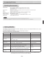
Operating Environment
Supported OS:
Supported PC:
CPU:
Memory:
Free hard disk space:
Display resolution:
Peripheral devices:
Web browser:
Microsoft Windows 2000 Professional (Service Pack 4 or later)/
XP (HomeEdition / Professional Edition Service Pack 2 or later)/
Vista (32 bit version)
IBM PC/AT or completely compatible machines that operate the aforementioned OS
Pentium III 1.2GHz or later
Windows 2000 (128 MB or bigger), Windows XP (256 MB or bigger)
40 MB or greate (not including space for storing images)
800 × 600 pixels or higher
a CD-ROM /DVD-ROM drive, a standard USB port (USB 1.1 or 2.0)
Internet Explorer 6.0 or later
Notice
• All operations are not guaranteed under the aforementioned operating environment.
• Windows 95, 98SE/Me, NT, 2000 Server, Server 2003, and Vista (64 bit version) are not supported.
Factory defaults
The "Settings" menu of the "PLUS TOOLBOX" dedicated software on the included CD-ROM can be used to
change the captureboard's settings.
For setting instructions, see the separate "Software Operating Instructions".
Below are the setting items and factory defaults.
Setting item
Description
Factory default
Color
Scanning color mode Color/Black & White
Black & White
Density
Scanning density Standard/Dark
Standard
Date/time setting
Set of the date and time for the time stamp
Japan Standard Time
File Format
Sets the format of the images stored on the USB memory
device.
JPEG / PNG / PDF
PNG
Paper Size
A4/Letter
A4
Aspect Ratio
Sets the aspect ratio for printed images.
Original Image / Match Paper Size
Match Paper Size
Erase Reminder
Sheet rear surface erase reminder function: Disable/Enable
Disable
Restrict color mode
Setting for disabling printing/storing in the color mode
Disable
Resolution
Selection of resolution for images stored in the memory and
images transferred to the computer : Standard
Standard
Standard : 1/2 the vertical/horizontal size of the scanned image
High : 1/1 the vertical/horizontal size of the scanned image
Header/footer (date/
time stamp)
Upon shipment from factory :
Writing of date/time when printing/storing : Enabled/Disabled
Original editing : Header/footer data output *
Enabled
* The date/time stamp can be displayed at the user's discretion as part of the header/footer data.
Upon shipment from the factory, only the time stamp is displayed.
E-31
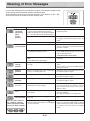
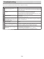
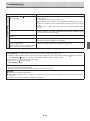
Meaning of Error Messages
If any of the following flashing indications appear in the display window of the
control panel, please check the matters described below.
Error messages will flash for 5 seconds; however, error displays of “E4”, “E5” ,
“E6”and “E8” will be lit steadily after the flashing stops.
Error Display Number
Printer not
connected
No printing
paper
Printer
problem
Problem and Solution
• Is the printer cable connected?
• Connect the printer properly and switch on
• Is power being supplied to the printer?
the printer power.
• When the printer uses an AC power adapter, is the cable disconnected somewhere?
• Has paper been set in the printer?
• Turn the power of the printer off and then
on again, and load the printer with A4
paper.
• Is the printer error indicator flashing (or lit)? • Read the printer instruction manual.
USB Memory
• Is the USB memory unformatted.
not recognized
• This unit supports the FAT and FAT 32
formats. Perform the formatting with the
personal computer.
• Is a USB memory that is not supported by • Please see our home page for information
the Captureboard being used?
about USB memories that can be used
with the Captureboard.
( http://www.plus-vision.com )
• Is the USB memory device plugged in • Please check the operation with a personal
fully?
computer.
• Is the USB memory damaged?
USB Memory
storage
problem
• An error occurred during USB memory • Please perform USB memory storage
storage.
again.
• Do not insert or remove the USB memory
during processing.
Reading
problem
• There is a lighting fault of the reading light • Unplug the power plug from the power outsource, or a read signal error.
let and then plug it in again.
System error
• There is a memory or internal fault.
Page detection error
• The pages are not being properly detected. • Unplug the power plug from the power outlet and then plug it in again.
Security
protection
• You have attempted to use a function dis- • The settings can be changed using the
abled by the security settings.
exclusive software. For details, contact
your nearby PLUS Vision sales office,
dealer or store.
Restrict color
mode
• Setting for disabling printing/storing in the • Can be changed in the captureboard's
"Function Settings".
color mode.
For setting instructions, see page E-28.
• Unplug the power plug from the power outlet and then plug it in again.
USB memory
• USB memory device is not plugged into the • Plug the USB memory device into the USB
not connected
main unit.
port.
• Did you press the ON/Standby
button • A USB memory device is plugged into the
When the “USb” letter diswhile the USB memory device was plugged
main unit. When the USB memory device
play is flowing...Warning
into the main unit?
is disconnected, the power will be switched
that disconnection of USB
off and the unit will enter the standby
memory has been forgotten
mode.
E-32
Meaning of Error Messages
Problem and Solution
Error Display Number
USB Memory
is full
• There is no available space.
• Please delete unnecessary data using a
personal computer (See Page E-26, E-27).
An unsupported printer
is connected
• A printer that is not supported by the • Press the ON/Standby
button and
Captureboard has been connected.
switch off the power. When a record is
required, switch on the power and save to
USB memory.
Time setting
error
• An error has arisen when setting the time.
Printer connection restrictions
• Printer connection restrictions are currently • For details, contact your nearby PLUS
being applied.
Vision sales office, dealer or store.
• When the ON/Standby
button is
pressed, the display switches to "c1". Start
the setting over from the year.
If the problem persists, please contact your nearby PLUS Vision sales office, dealer, or store.
E-33
Troubleshooting
Please check the following matters before making a request for servicing.
Condition
Captureboard Related
Pressing the ON/Standby
not switch on the power.
Please Check
button does • Check whether the cable of the AC power adapter is disconnected from
the DC connector of the Captureboard or the wall outlet. (Unplug the AC
power cable from the outlet, wait several seconds and then plug it back
into the outlet again.)
Writing on the sheet is not erased with • Is a marker other than a dedicated marker being used?
the eraser.
• Is an eraser other than a dedicated eraser being used?
• Has a soiled eraser been used on the erased surface?
(Wring the water out of a moistened cloth and wipe carefully. Also, replace
the sponge with a new one and use the eraser.)
Portions of writing or lines are not printed • Portions of blurred characters or thin lines may not be printed or stored in
or stored in memory.
USB memory.
• Change Density setting to “Dark”.
The copy is soiled.
• Is there a lot of marker refuse adhering to the sheet?
(The image data is dirty at the time of
(When soiled, moisten a soft cloth with water, wring well, and wipe the
printing, USB memory storage, or persheet in a stroking manner.)
sonal computer saving.)
The black ink mixes into other color in the • Check the density indicator, and select standard density if the setting is
case of Color Mode.
darker.
When the Captureboard and PC are con- • Has the USB driver in the CD-ROM been properly registered in the device
nected, the supplied utility program does
manager? (An exclamation mark (!) will be affixed if it has not been regisnot operate after installation of the USB
tered.) (If not registered, delete the USB driver and reinstall it.)
driver
(Uninstall the Captureboard software and then install it again.)
When the Captureboard and PC are con- • Check whether the Captureboard is in an operable condition, and whether
nected, the PC does not recognize the
the USB cable is connected properly.
Captureboard
• Is the Captureboard connected to the PC via a USB hub?
(Connect the Captureboard directly to the USB port of the PC.)
* If the problem persists, please contact your nearby PLUS Vision sales office, dealer, or store.
E-34
Troubleshooting
Condition
Printer Related
A press of the Print
result in printing.
Please Check
button does not • Check that the power cable of the printer and the printer cable are securely connected.
• Check that the printer power indicator is lit.
• Check that the error indicators of the Captureboard and the printer are not
lit.
• If the error indicator of the Captureboard is flashing, please see Page
E-32.
(Please see the printer instruction manual for information about printer
errors.)
The paper feed is abnormal.
• Possible causes include damp paper, overly thin or thick paper, only one
sheet of paper is set, and a curved setting of the paper. (Please see the
instruction manual for your printer.)
An altered color is printed, not the speci- • Please replace the print cartridges with new ones.
fied color.
There is no printing.
• Check that the print cartridge is properly set.
• Check that the print cartridge is not plugged.
• Print is very pale, there are white lines Is the print cartridge’s nozzle partially choked?
on it, or page is dirty.
◆ Make a test print and check the conditions of the nozzle.
• Printed colors are very different from
those of the markers that were used.
Test Printing (This is done with the captureboard's function settings. See page E-28.)
1) With the captureboard's power turned on (the display window lit), press and hold in the Density
the ON/Standby
button. "F1" appears on the display window (function settings mode).
2) Use the + or – button to display "F9" (test print).
3) Press the Save button to finalize.
button, then press
* Test printing starts.
Check the print
• Is the each color line printed uniformly?
• Are there missing dots, pale lines, lines with thinner ink than others, etc.?
Remedy
◆ If the nozzle is partially choked, clean it.
◆ If the quality of the print does not improve even though the nozzle has been cleaned, wipe off the ink on the surface of
te nozzle.
For details, see the “User’s Guide” included with the printer.
* Please see your printer manual for information about printing problems, printer maintenance, and details related to printing.
E-35
Specifications
BOARD TYPE (Model name)
Installation method
Form
External dimensions
(T-shaped legs*¹)
Main unit weight
Standard (C-12S)
Wide (C-12W)
Self-standing (T-shaped legs), or wall mounting
W1470 × D700 × H1970*² mm
W1970 × D700 × H1970*² mm
31 kg*³
35 kg*³
T-shaped legs weight
9.6 kg
Panel Size
W1300 × H920 mm
Effective reading size
W1280 × H900 mm
W1800 × H920 mm
W1780 × H900 mm
Number of Pages
Paging
2
Endless in one direction (Horizontal scrolling)
Drive method
BOARD
Reading method
Sheet movement
CCD sensor reduction optical system
Reading illumination
light source
Reading resolution
Reading time
RGB LED
Main scanning direction (vertical sheet surface) 2.4 dots/mm (60 dpi or equivalent)
Sub scanning direction (horizontal sheet surface) 2.4 dots/mm (60 dpi or equivalent)
Black & white: approx. 15 s
Color: approx. 23 s
Type
Memory
Control panel
USB1.1 or USB2.0 full-speed mode*5
ON/Standby, +, −, Print, Save, Reprint, Color, Density, Feed
LED Indicators
Density, Color
Clock
Power supply
AC power adapter
Operating
conditions
Temperature:
Miscellaneous
PNG, JPEG and PDF format
Control buttons
PC connection
Recording
Section
FAT 12, 16, 32
File format
Display
Added functions
USB Flash memory*4
Compatible FAT types
Interface
Black & white: approx. 20 s
Color: approx. 31 s
7-Segment (Status of PC connection, Error#),
Used for the timestamp and for file dating properties
(Includes backup battery for when there is a loss of power)
Transfer of sheet surface image data via USB (TWAIN supported)
Input : AC100–240V/50–60 Hz, Max 1.5 A
Output : DC 24 V, 2.71 A
10–35°C
Humidity:
Printer interface
30–85% (No condensation)
USB1.1 or USB2.0 full-speed mode compliant printers are supported
Ruled lines
Miscellaneous
None
Dedicated markers (black, red, blue, and green)
Remarks
*1: Height adjustable in three stages of 1770, 1870, and 1970 mm.
*2: H (height) reflects the maximum value of the dimension.
*3: Weight of printer is not included.
*4: USB flash memory is not supplied.
*5: High-speed is not supported.
• Please note that the appearance of the main unit, the supplied printer, specifications, and other items are subject to change
without notice for the purpose of quality improvement.
• Depending on the product that you have purchased, the printer and (T-shaped) stand may be sold separately.
• This machine contains eParts of the eSOL, Co., Ltd.
E-36
Appendix
Connections and Wiring Diagram
The connections and wiring diagram below is included here for checking the connections.
* For connection of the captureboard and computer, see the separate "Software Operation Manual".
[Captureboard and Printer Connections Diagram]
Back surface
To DC INPUT connector
To Printer connector
To USB connector
USB cable (supplied)
To DC input connector
Printer
AC power adapter (supplied)
Printer AC power adapter
supplied with the printer
* Appearance of printer is for illustration purposes.
Note
The AC power adapters of accessories and printers that have been verified to be operation many differ from the
ones shown on the connections diagram (they may be of the built-in or mounted-on type).
E-37