1
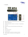
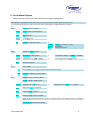
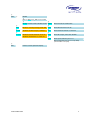
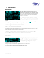
Ambient Recording GmbH
Schleissheimer Strasse 181c
D – 80797 Munich
Tel.: +49 89 3605510-0
Fax: +49 89 651855
[email protected]
www.ambient.de
Table of contents
page
1.
Introduction
2
2.
Package Contents
3
3.
Safety instructions
3
4.
Powering
4
5.
Description
5
6.
Setup Menu Diagram
6
7.
Menu Description
8
7.1
Generator: Jam, TC, UB Settings
9
7.2
Sync Settings
12
7.3
Time Code Setting
15
7.4
System Settings
16
7.5
ACN Ambient Clockit Network
18
8.
LED indications
22
9.
Firmware update
22
10.
Physical specifications
23
11.
Warranty & Approvals, CE, FCC
24 ff
www.ambient.de
1
1. Introduction
The Ambient ACL 204 Lockit box continues the line of our highly accurate portable
synchronizers, which have become an indispensable tool in modern workflows where multi
camera shoots and dual system sound is the rule.
Like its predecessors, it provides time code with a deviation of less than +/- 0.1 ppm of a
given reference and a sync signal locked to this. The Clockit time code products can be
calibrated to this reference in the field using the Clockit Controller ACC501, providing the
same accuracy still after years, compensating the usual aging of the crystals, and opening
possibilities which are unique to the Clockit approach.
What counts on a set is that all recording devices run on the same speed, and with the
Clockit method of being able to tune the devices, this goal can be achieved.
The reference for tuning may be a GPS signal, but just as well the time code of the master
recorder or camera or a video reference signal generated by the studio / OB-truck’s
synchronizer.
In addition to those classical features of the Clockit product range, the ACL 204 features a
wireless network module and a serial data port, so the status of each unit on set can be
monitored and metadata of the connected devices can be communicated to the Ambient
Clockit Network ACN Master. ACN also permits to sync the ACL 204 remotely and write back
metadata to the recorders.
www.ambient.de
2
2. Package Contents
-
ACL204 synchronizer
ACL-T204, protective leather pouch
LTC-OUT cable, Lemo JGG.305 to BNC right angle connector
BNC cable, BNC to BNC right angle connector
Manual
3. Safety instructions
For your own safety and trouble-free use of your Lockit ACL 204 please carefully read
through the instructions below. Always keep a copy of these instructions and hand them out
with the unit to other users.
This unit is exclusively intended for indoor use. Keep it safe and away from water, rain and
humidity and dry under all circumstances even when powered off. Clean gently with a
slightly moistened cloth and never let water, detergents or liquids of any kind get into the
unit as this will imply the risk of short circuits and electrical hazard.
Keep distant from sources of heat and never expose to direct sunlight. Admissible ambience
temperature is from +5° to +50° Celsius.
Do not throw or expose to mechanical impact and keep it safe from hard vibrations.
Only use genuine accessories such as cables antennae etc. which have been supplied by an
authorized dealer. Always observe integrity and the pertinent compatibility with all units
connected to.
Do not perform software updates in situations the integrity of mains supply can not be
granted such as thunderstorms and remove connections from and to all devices directly or in
directly connected to mains.
Only use intended batteries type Mignon AA with 1.5V. Watch correct polarity when
inserting the batteries, instructions can be found in the manual and on the device itself.
Disregard of handling may cause battery leakage or even risk of explosion.
To maintain secure electrical contact the batteries are loaded with high spring tension and
can shoot out of the compartment if opened without attention. Always secure the outer
battery contact and release slowly when accessing the compartment.
Proper recycling of used batteries might mandatory be instructed by local law. Please check
for requirements and dispose at foreseen institutions. With regard to environment only
dispose completely discharged batteries.
www.ambient.de
3
When powering from external sources remove the batteries and put the power switch into
the "OFF" position. Pay attention to the use of LPS sources in compliance to part 2.5 of EN
60950-1.
When using the wireless connection of the Lockit ACL 204 place it centrally and keep it
distant from sources of possible interference such as microwaves or electrical devices with
large metal surfaces.
If possible always use the integrated antenna. If the application of an external antenna
seems mandatory only use the original part directly attached to the socket. Extension or use
of 3rd party accessories is not licit.
Never open the unit. Inappropriate and unauthorized access will void the warranty and
imply possible risk of harm to the user.
When disposing the unit follow the legal requirements for recycling electronic equipment.
4. Powering
The ACL 204 can be powered:
-
-
by 2 pcs. Type Mignon AA batteries (Alkaline, NiMH rechargeable or Li-Ion). Set
correct battery type in configuration for reliable low voltage warning.
Pay attention to insert with correct polarity as shown on label, insert outer with “+”
first, inner with “-“ first. Push down battery hinge and close slider.
5 to 18 Volts DC via pin 4 of Lemo “A” socket
5 Volts DC via the USB socket.
If powered from external, the power switch is bypassed
-
powered from internal battery
-
powered from external, Lemo socket A pin 4
-
powered from USB
-
power present on Lemo and USB
Note: current time code is lost when power is removed. The settings are stored, the unit will
power up with the last configuration used. Should power be removed while in SYNC menu
with invalid settings chosen, the ACL 204 will power up with the last valid configuration.
www.ambient.de
4
5. Description
①
② ③ ④ ⑤⑥⑦
⑧
⑨
⑩
⑪
①
Battery compartment slider to be pushed left/right for access to switches or batteries
②
USB socket type Mini-B 5-pin
③
Configuration switch (further “config switch”, ↓ for pushing in, ↔ for toggle leO/right)
④
Power switch
⑤
IR transceiver, used to set and check the ACL 204 from the ACC501 controller
⑥
Display
⑦
Signal LEDs
⑧
External antenna connector
⑨
Sync signal connector
⑩
Lemo 5-pin socket “B”: time code in, out / serial port tx-rx / DC-out
⑪
Lemo 5-pin socket “A”: time code in, out / ascii / tune signal / DC-in
www.ambient.de
5
6. Setup Menu Diagram
When entering a menu, the active parameter setting is highlighted.
MAIN DISPLAY, showing time code, frame rate, sync rate, jam mode, network channel, battery status
↓ push select switch down to enter main menu and to select opYons, toggle leO/right to navigate
↓
GEN
JamTC ↔ Edit ↔ Offset
↓
↓
JamTC:
AUTO ↔ OFF ↔ manual/once
↓
HH:MM:SS:FF
Edit:
↓
+/- 00.05 frames
Offset:
↓
UB
JamUB ↔ Edit-UB ↔ EXIT
↓
JamUB:
normal ↔ manual ↔ insert
Edit-UB:
00:00:00:FF
EXIT:
back to main menu
↓
AUDIO ↔ VIDEO ↔ OFF
SYNC
↓
↓
Wordclock ↔ Black Audio
Sample Rate: 32000 …↔48000…↔192000
AUDIO:
↓
↓
PAL↔NTSC…↔ 1080i…1080psf
Frs: 23.976↔24…↔59.94 ↔ 60
VIDEO:
↓
↓
NO SYNC OUTPUT
OFF:
↓
TC
FPS ↔ MTC
↓
↓
FPS
FPS: 23.976 ↔ 24 ↔ 25 ↔ 29.97 ↔ 30 ↔ 29.97D ↔ 30D
↓
MTC
MTCout ↔ MIDI>LTC ↔ LTC>MIDI
↓
SYS
↓
Config ↔ INFO ↔ Factory Reset
↓
Display ↔BNC ↔USB ↔ BAT
↓
AutoOff: never ↔ 5sec ↔ … ↔ 5min
Display: Brightness: 0…↔5↔…10
↓
↓
BNC Load: Single ↔ Dual/3D
BNC:
↓
USB
USB Port: MTC ↔ COM
↓
BAT
Battery type: Li ↔ Alk ↔ NiMH
↓
INFO: displays device information: serial no., firmware version, mac address version, mac address
↓
Factory Reset: loads default settings
www.ambient.de
6
↓
ACN
↓
↓
JAM
↓
C-JAM
↓
TX / RX
↓
EXIT
MODE
↓
OFF ↔ JAM ↔ C_JAM ↔ TX ↔ RX
↓
↓
MODE↔CHNL↔ANT↔PWR↔SYNC MODE
↓
Mode for remote jamming of ACL 204 CHNL
↓
Mode for continuous jam / autosync
ANT
↓
Mode to transmit external recrun TC
PWR
Mode to receive free- or recrun TC
↓
SYNC
Back one level to mode select
Select ACN channel 11 to 26
Select antenna internal ↔ external
Select RF output power 8 to 18 dBm
Send sync broadcast: yes ↔ no
Start continuous jam: yes ↔ no (C-JAM)
(not available in TX / RX)
Return to main operation display
www.ambient.de
7
7. Menu Description
MAIN DISPLAY
The main display is the normal operation mode. It
displays the most important status information. These
are the time code momentarily running, the sync signal
type and rate, the time code frame rate, and various
additional information:
“X” next to the Fps indication indicates a cross-jam
mode, i.e. the time code rate is not consistent with the
sync rate, but compatible and in sync at each second’s
transition.
“A” in upper left corner indicates the jam mode “auto”, the lock symbol
external jamming available, “M” indicates manual / once.
indicates “off” – no
“+00:00” top right beside the battery indicates the offset.
“COM” or “MTC” show the status of the USB port.
Information related to ACN will be displayed once it is activated (on above screen shot it is in “Jam”
mode, channel 20, external antenna and LNA activated).
If the display is switched off (power save), pushing the config switch once will turn it on again
without doing any changes. Also, external time code jam activates the display.
MAIN MENU
Pushing the config switch once enters the main menu
screen. The main operation parameters are further
displayed. In this screen, you can select the different
settings by pushing the config switch. Navigate by
toggling the config switch left or right.
Pushing the config switch when EXIT is highlighted exits to the main screen.
If no action is done, the unit will return to the main screen as well.
www.ambient.de
8
GEN MENU
In the GENenrator menu, you can edit the jam mode,
edit the time and set an offset of the time code output
against the jammed time.
Under UB, you can display and manage User Bits.
GEN > JamTC
In the JamTC settings, you can select from different jam behaviors: Navigate toggling left/right, push
to select.
“AUTO” – the ACL 204 will behave as used to from the
former Lockit boxes. It will jam once time code is
detected, but not re-jam while time code is
continuously present. As long as time code is present, the “A” changes to
indicating that the
unit is not ready to re-jam. If the time code is disconnected for 3 or more seconds, the “A” reappears
to indicate that the unit will jam again once time code is received.
“OFF” – the ACL 204 does not jam to external time
code. This setting is useful if you set the unit manually
and not to be jammed by incoming time code.
The
in top left corner shows that the input is locked.
“manual/once” – the ACL 204 jams once to external
time code, but then will not jam again but close
the jam port. Once jammed, the “M” changes to
indicating that the unit can not be jammed from
outside. This setting is useful if the unit is to be jammed from external time code but then not to be
changed by incoming signal anymore. Also can be used should a Lockit box be used to re-jam
cameras in intervals and using a bi-directional time code cable, which would, with some cameras that
put out time code permanently even in “ext. TC” mode like the Alexa, lead to resetting the ACL 204 in
“AUTO” mode.
To reactivate the jam port, just push the config switch repeatedly going >GEN>JamTC>manual/once>
and exit. The “M” indicator appears again, the unit is ready to be jammed once again.
CAUTION! Resetting the generator will restart the video or audio sync signal, doing this
while recording will result in a corrupted file.
www.ambient.de
9
GEN>EDIT
In this screen, you can edit a time code value manually.
Decrease or increase by toggling left/right. Holding
left/right is fast backward/ forward. Push to select.
Pushing the config switch while on the frames position
sets the time. To avoid inadvertently changing the time code, you will be asked:
Pushing the config switch while “old” is highlighted discards the changes and returns to the main
menu.
Pushing the config switch while “new” is highlighted will set the generator to the selected value.
CAUTION! Resetting the generator will restart the video or audio sync signal, doing this
while recording will result in a corrupted file.
GEN>OFFSET
An offset can be entered between the jammed time
code and the time code on the output of the ACL 204.
Use this to compensate the processing delay that some
file base cameras produce.
This shifts only the time code, the sync signal stays locked to the frame start of the jammed time
code running in background.
The offset has a range of +/- 10 frames in 0.05 frames steps (equals 2 ms at 25 fps).
The selected offset is displayed next to the time code
in main window and menus.
www.ambient.de
10
GEN > UB
In the GEN > user bit menu, the user bits are being
displayed. The user bits can be edited manually, and
the jam behavior managed.
JamUB
Under JamUB, the jamming behavior is managed:
normal: the user bits are being taken from external
time code
manual: the user bits are not being overwritten by
external time code. This mode is to be used if you want
a custom entry, like date and camera Id for instance.
insert: user bits can be inserted “on the fly”. Note: if
the source time code was unplugged for more than 3 seconds and reconnected, the ACL 204 will rejam. For just inserting changed user bits after interrupted time code, you must also set the ACL 204
to “jam once” or “off” in the jamTC menu.
Edit-UB
In Edit-UB, the user bits can be edited manually.
Decrease or increase by toggling left/right. Holding
left/right is fast backward/ forward. Push to select
value, curser jumps to next digit.
After finishing, selecting the new value needs to be
confirmed – “use new”, or the menu can be left by
cancelling – “use old”.
EXIT
As the user bits are only displayed in this menu, we
added a way to exit without any changes quickly.
www.ambient.de
11
SYNC MENU
The SYNC menu lets you set the sync signal format,
type and rate. Select the different settings by pushing
the config switch. Navigate by toggling the config
switch left or right.
“VIDEO” – selects a genlock video sync signal. Use this to clock video cameras (and some advanced
audio recorders)
“AUDIO” - selects a wordclock or black audio sync
signal. Use this to clock most professional audio
recorders.
“PPF” is a pulse per frame to trigger certain cameras.
“OFF” – deactivates any sync signal generator, reducing the power consumption by almost 50%. Use
this if time code only is required.
SYNC>VIDEO
Pushing the config switch while VIDEO is
highlighted takes you to the genlock settings. The
curser is on the signal type. Change by toggling
left/right. Select by pushing the config switch.
Types available:
NTSC (480i), PAL (576i), 720p, 1080i, 1080p, 1080PsF
Pushing the config switch selects and takes you to the rates setting.
Rates available:
23.976, 24, 25, 29.97, 30, 50, 59.97, 60 pictures per
second.
Not all rates are available with all of the signal types,
only those which are specified by SMPTE / EBU / ITU.
Pushing the config switch selects. If any changes have been selected, you will be asked to confirm:
Pushing the config switch while “old” is highlighted
discards the changes and returns to the main menu.
Pushing the config switch while “new” is highlighted
will set the sync signal to the selected format.
www.ambient.de
12
If the selected video format is incompatible to the currently set time code value, a message appears:
You have no choice but to press the config switch and
are automatically taken to the time code rate setting:
While the time code is inconsistent with the video rate,
a “!” is shown next to the time code Fps indication.
Select a frame rate that matches your video signal.
Again, you will be asked to confirm the new frame rate.
Navigate to “new” and push the config switch. If you
do not adjust the time code rate to a value compatible
to the video signal selected, you will be taken back to
the video sync signal setting.
There is no way out of this loop with an invalid combination!
Note: Any combination of a “PAL-Area” video reference signal with an non-integer time code
(23.976 fps, 29.97 fps) or a ”NTSC-Area” video reference signal with an integer time code (24 fps,
25 fps, 30 fps) is considered invalid as they will drift against each other and it is not possible to
provide a reference signal locked to the time code.
Cross-jam configurations, such as a 23.976 frames video signal with a 29.97 fps time code are
allowed. An “X” will be displayed next to the Fps indication.
Once a valid combination has been selected and confirmed, you are back in the main menu.
CAUTION! Resetting the generator will restart the video or audio sync signal, doing this
while recording will result in a corrupted file.
SYNC>AUDIO
Pushing the config switch while AUDIO is highlighted
takes you to the audio sync settings. The curser is on
the signal type selection. Change by toggling left/right.
Select by pushing the config switch.
Types available: Wordclock, Black Audio (AES3)
Pushing the config switch selects and takes you to the rates setting.
Sample rates available: 32 KHz, 44.1 KHz, 48 KHz, 88.2 KHz, 96 KHz, 176.4 KHz, 192 KHz and their
respective pull-up / pull-down rates.
www.ambient.de
13
SYNC>PPF
The “pulse per frame” is a trigger for the sensor of
certain cameras. The signal is present on pin 3 of Lemo
socket A. 1, 2, 4 periods per frame are available, and
selection if the signal shall start with a rising or falling
edge.
As with any change of the sync settings, the user is
asked to confirm.
SYNC>OFF
The FPGA chip is powered off, no sync signal is
generated. Use this in time code only applications to
save battery life. Confirm by navigating the curser to
“new”.
www.ambient.de
14
TC MENU
Enter the TC menu to adjust the time code frame rate.
Next is the selection for the TC frame rate and the Midi
Time Code setting:
TC > FPS
Select “FPS”
Adjust by toggling the config switch left/right,
push in to select new frame rate:
Rates: 23.976, 24, 25, 29.97, 30, 29.97D, 30D fps (D = drop frame)
If settings are changed, confirmation is required:
Pushing the config switch while “old” is highlighted,
discards the changes and returns to the main menu.
Pushing the config switch while “new” is highlighted
will set the time code signal to the selected rate.
If the selected time code frame rate is incompatible to
the currently set video signal type, a warning message
appears:
The LED will double flash and “!” is flashing next to the
TC frame rate. You have no choice but to press the
config switch and are automatically taken to VIDEO:
Select a video signal that matches your time code
frame rate. If you do not adjust video signal to a value
compatible to the time code frame rate selected, you
will be taken back to the TC setting.
There is no way out of this loop with an invalid combination!
See above in SYNC>VIDEO.
TC > MTC
Select MTC to control the Midi Time Code options:
Note: selecting a MTC mode will switch the USB port to
Midi/Audio interface.
www.ambient.de
15
MTCout: this is the default mode. The ACL 204 always
puts out MTC, unless the USB port is set to COM (see
SYS > Config > USB).
MIDI>LTC: MTC received through USB will be converted
into LTC and put out on both Lemo sockets, pin 5.
LTC>MIDI: LTC received on Lemo/TC pin 2 will be
converted and put out as MTC via USB.
SYS MENU
The SYS menu serves to configure various parameters,
in this release version the display behavior and the
BNC sync signal impedance are set. Push the config
switch to enter.
SYS > CONFIG
Enter the configuration by pushing in the config switch
Navigate to DISPLAY, BNC,USB or BAT, push the config
switch to select.
SYS > CONFIG>DISPLAY
Adjust display brightness from 1 to 10 toggling the
config switch left/right. Push in to select value.
The curser will jump to the Auto-off settings:
Select after what time the display shuts off after
entering the main operation display.
Choices are:
Never – 5 seconds – 30 seconds – 1 minute – 5 minutes
Select by toggling the config switch left/right. Push in to select value.
www.ambient.de
16
SYS > CONFIG>BNC
Determine the output impedance for the video sync
signal:
Single: 75 Ohms for connecting to one video camera’s
genlock input.
Dual/3D: 37.5 Ohms for splitting to two cameras’ genlock input.
Select by toggling the config switch left/right. Push in to select mode.
SYS > CONFIG>USB
Default setting is MTC, the ACL 204 is recognized
as Midi/Audio interface when connected to
computer. Set to COM for updating.
SYS > CONFIG>BAT
Select battery type for correct voltage readout and low
battery warning / flashing.
Li = Lithium-Ion (non-rechargeable batteries!) 1,5V, Alk = alkaline batteries 1,5V, NiMH = NickelMetal-Hydrid rechargeable batteries 1.2 V
SYS>INFO
Select INFO to display information about the
ACL204:
Serial Number
Main firmware version
FPGA firmware version
Mac address
SYS>Factory Reset
This restores factory defaults: Sync is off, TC is 25 fps,
ACN is off, display brightness at 3, display auto-off 30
sec., TC-offset reset, USB to MTC.
Time code is not lost, battery type not changed, tune
value unaltered.
www.ambient.de
17
ACN MENU
The ACN menu accesses the Ambient Clockit Network
configuration.
When coming from “off” setting, first the mode must
be selected.
In present firmware version 3.10, new modes have
been added:
Jam – the former “BASIC” used for wireless manual
jamming; C-Jam – the “continuous jam”; TX-RX for
transmitting a record-run time code from external
source.
ACN > JAM
The JAM mode allows to send a sync command to
other ACN-TL or ACL 204 devices, or receive sync
command from them. This serves to remotely sync all
units on the set. First, the menu asks to select the
wireless channel. The CHNL setting allows you to select
between 16 network channels within the 2.4 GHz
range.
The channel can be changed later.
The settings menu is left upon selection.
Selecting ACN again give access to further options:
ACN > JAM>ANT
Select internal or external antenna and power the low
noise amplifier LNA for the receiver on or off. The LNA
draws power, so it is recommended only should the
reception of data be insufficient without. Default
setting is internal antenna, for activating the external
antenna a PIN code is required.
FFC regulations force us to have the selection of
external antenna code protected. Enter the PIN
code by toggling left / right and select by enter.
Please contact your vendor or Ambient Recording for
obtaining the code.
If the external antenna is activated, the antenna
symbol on the bottom right of the display is shown, as
well as activated LNA, see next page.
www.ambient.de
18
ACN > JAM>PWR
PWR lets you increase the output power of the
transmitter. Default is 8 dBm, up to 18 dBm is possible.
Again, the PIN is required.
ACN > JAM>SYNC
Selecting SYNC opens the screen for sending a sync
command to all ACN-TL or ACL 204 in reach which are
on the same channel and in JAM mode. Syncing is only
possible from a device that has a valid time code
(jammed or set manually), signaled by green flashing
LED.
Default is on no, toggle to yes and push to enter.
After sending out the sync command including time
code and user bit, the other units reply and the
number of units which replied and were successfully
synced is displayed.
A device that received a sync command will memorize
when the sync command was received. The
transmitting device also memorizes the event. The
information is displayed when ACN is selected from the
main menu.
There may be various reasons for a “sync failed” returned:
For time code:
-
If the frame rates of sending and receiving device do not match (integer vs. noninteger frame rates like 25 fps and 29.97 fps, the sync command is rejected.
If “OFF” is selected in the GEN>JamTC settings.
If “manual/once” is selected in the GEN>JamTC settings and the device has been
jammed before.
www.ambient.de
19
For user bits:
-
if the GEN>UB>JamUB is set to “manual”
ACN > C- JAM
C-JAM is a continuous jam mode. Set up channel,
antenna, RF power and LNA as above in JAM mode.
When done, select SYNC. In the next display, the
continuous jam is initiated. The device used for
sending the continuous jam command is master.
After sending the continuous jam command, the jam
success or fail of other devices ACL 204 or ACN-TL is
displayed.
Condition for fail is as in JAM mode, see above.
Any ACL 204 or ACN-TL in range that has not been
synced or has an offset bigger than 0.5 seconds will be
jammed. After the initial c-jam, the master sends a
sync command every five seconds. Slave units display
“sync rcvd” and their LED goes to solid green for a
second. If synching fails, the LED goes red and “sync
failed” will be displayed.
The slave Lockits now compare their own time with
the regularly received time stamps and will adjust their
tune value to stay closely in sync with the master, the
system latency is down to half a video line (SD) if all
Lockits are well in tune to each other initially. The
latency in µs, measured time in seconds since start of
c-jam, current tune value, proposed tune value are
displayed in an “expert view” window, accessed by
selecting SYS>INFO and then pushing the toggle switch
to right (line 1). Line 2 is debug info, line 3 used tune value.
In this mode, a unit that was slave and has been power cycled (for instance for changing batteries)
will automatically re-sync when booted. The master unit will be in c-jam mode, but not send sync
signals after reboot. Should it become necessary to reboot the master, a former slave may be used to
initiate the c-jam and become master. This way, the set time code is maintained. It is recommended
though to stay with one master and to re-sync the set after power cycling, this way it can be avoided
to have more than one master on location which may lead to unpredictable errors.
www.ambient.de
20
ACN > TX / RX
TX is a wireless transmission of external time code
present on the Lemo/TC input. This is intended for
transmitting a record-run time code to another ACN-TL
or ACL 204 which is in RX mode.
Set up channel, antenna, RF power and LNA as above
in JAM mode.
Once progressing time code is detected, the ACL204
jams to it and sends a jam command to the slaves.
When external time code stops, a stop command is sent to the slaves.
If static time code value is recognized, as put out by a video camera or Sound Devices recorder, the
time code is stopped and a static time code is put out on the time code output of the slaves as well
as on the output of the unit that is in TX.
This feature makes it possible to remotely start and stop recording of audio recorders, cameras and
video recorders which support being triggered by time code.
Please note that in TX / RX record run time code
mode no sync signal will be generated
EXIT
Exits to the main operation screen.
www.ambient.de
21
8. LED Indications
As used to from former devices of the Clockit Time Code family, the ACL 204 has a red and a
green flashing LED to display operation and battery status:
0
1
2
3
4 seconds:
●
●
●
●
●
red flashing in 1 second intervals: running, but not jammed or set.
● ● ● ● ● green flashing in 1 second intervals: running, jammed or set manually.
This is the normal operation mode.
●
●●
●●
red double flash every 2seconds: battery low, not jammed or set.
●
●●
●●
green double flash every 2seconds: battery low, jammed or set.
● ●● ●● ●● ●●
red double flash every second: TC / video not sync, not jammed or set.
● ●● ●● ●● ●●
green double flash every second: TC / video not sync, jammed or set.
The double flash on every second is shown while invalid combinations are configured or
while syncing the genlock signal to time code after configuration changes or jamming.
● ●●●
● ●●●
combination of not sync and low battery, not set or jammed.
● ●●●
● ●●●
combination of not sync and low battery, set or jammed.
● ● ● ● ● ● ● ● ● ● alternating colors during firmware update.
9. Firmware Update
New features, improvement and fixes for the ACL 204 will be available for download from
our website:
http://www.ambient.de/en/produkte/ambient-recording/clockit-timecode/acl-204.html
The firmware update comes as an executable file including the programming interface and
the firmware file.
Connect the ACL 204 to a computer running a Microsoft Windows® operating system using a
USB cable to a type Mini-B connector and run the .exe.
Make sure the USB port is set to “COM” under menu System>Config>USB
Press the “UPDATE” button. Wait until the message “update successful” appears.
Factory reset is always recommended after a firmware update.
Contact us for bug reports and suggestions through our contact form.
www.ambient.de
22
10.
Physical specifications
Dimensions:
(L / W / H): 100 x 74 x 36 mm
Weight:
0.25 Kg (no batteries)
Power consumption: 90 mA (3 Volts, typical)
Connectors:
“A”:
Lemo series 0B 5-pin (matching connector FGG/JGG.0B.305.CLADxx)
pin 1:
pin 2:
pin 3:
pin 4:
pin 5:
“B”:
ground
LTC IN
ASCII IN / OUT
Tune reference 1.92 MHz out / DC-IN 5 to 18 Volts
LTC OUT
Lemo series 0B 5-pin (matching connector FGG/JGG.0B.305.CLADxx)
pin 1:
pin 2:
pin 3:
pin 4:
pin 5:
ground
LTC IN
ACN / RS232 TX
ACN / RS232 RX
LTC OUT / 3.3 Volts DC OUT
SYNC:
BNC coax 75 Ohms / 2x 75 Ohms parallel selectable
Antenna:
SMA-F
USB:
Mini-B 5-pin
www.ambient.de
23
11. Warranty & Approvals
Warranty
Ambient Recording GmbH warrants the Clockit ACL 204 synchronizer against defects in
materials and workmanship for a period of ONE (1) year from date of original retail
purchase. This is a non-transferable warranty that extends only to the original purchaser.
Ambient Recording GmbH will repair or replace the product at its discretion at no charge.
Warranty claims due to severe service conditions will be addressed on an individual basis.
THE WARRANTY AND REMEDIES SET FORTH ABOVE ARE EXCLUSIVE. AMBIENT RECORDING
GMBH DISCLAIMS ALL OTHER WARRANTIES, EXPRESS OR IMPLIED, INCLUDING WARRANTIES
OF MERCHANTABILITY AND FITNESS FOR A PARTICULAR PURPOSE. AMBIENT RECORDING
GMBH IS NOT RESPONSIBLE FOR SPECIAL, INCIDENTAL, OR CONSEQUENTIAL DAMAGES
ARISING FROM ANY BREACH OF WARRANTY OR UNDER ANY OTHER LEGAL THEORY. Because
some jurisdictions do not permit the exclusion or limitations set forth above, they may not
apply in all cases.
For all service, including warranty repair, please send the ACL 204, along with proof of
purchase date to your retailer, or, if not applicable, to:
Ambient Recording GmbH
Schleissheimer Str. 181 C
DE – 80797 Muenchen, Germany
Please obtain a return authorization through the contact form on our website before
sending in a unit.
www.ambient.de
24
CE Conformity Statement:
Declaration of Conformity
According to ISO/IEC Guide 22
Manufacturer’s Name:
Ambient Recording GmbH
Manufacturer’s Address:
Schleissheimer Str. 181 C, DE – 80797 Muenchen, Germany
declares that the product:
ACL 204 Synchronizer
is in conformity with:
- EN 60950-1:2006 + A11:2009+A1:2010+A12:2011+AC:2011
- EN 300 440-1 V1.6.1
- EN 300 440-2 V1.4.1
- EN 301 489-1 V1.9.2
- EN 301 489-3 V1.4.1
which is indicated and affirmed by the applied CE marking.
FCC Statement
The FCC requires that the following statements be included in this manual for ACL 204:
FCC § 15.19
This device complies with Part 15 of the FCC rules. Operation is subject to the following two
conditions: (1) This device may not cause harmful interference, and (2) this device must
accept any interference received, including interference that may cause undesired
operation.
Canada CNR-Gen Section 7.1.3
This device complies with Industry Canada licence-exempt RSS standard(s). Operation is
subject to the following two conditions:(1) this device may not cause interference, and (2)
this device must accept any interference, including interference that may cause undesired
operation of the device.
Le présent appareil est conforme aux CNR d'Industrie Canada applicables aux appareils radio
exempts de licence. L'exploitation est autorisée aux deux conditions suivantes : (1) l'appareil
ne doit pas produire de brouillage, et (2) l'utilisateur de l'appareil doit accepter tout
brouillage radioélectrique subi, même si le brouillage est susceptible d'en compromettre le
fonctionnement.
FCC § 15.21
Any changes or modifications not expressly approved by the party responsible for
compliance could void the user’s authority to operate the equipment.
FCC § 15.105
Note: This equipment has been tested and found to comply with the limits for a Class B
digital device, pursuant to part 15 of the FCC Rules. These limits are designed to provide
reasonable protection against harmful interference in a residential installation. This
equipment generates, uses and can radiate radio frequency energy and, if not installed and
used in accordance with the instructions, may cause harmful interference to radio
communications. However, there is no guarantee that interference will not occur in a
particular installation. If this equipment does cause harmful interference to radio or
www.ambient.de
25
television reception, which can be determined by turning the equipment off and on, the user
is encouraged to try to correct the interference by one or more of the following measures:
—Reorient or relocate the receiving antenna.
—Increase the separation between the equipment and receiver.
—Connect the equipment into an outlet on a circuit different from that to which the receiver
is connected.
—Consult the dealer or an experienced radio/TV technician for help.
ICES-003
This Class B digital apparatus complies with Canadian ICES-003.
Cet appareil numérique de la classe B est conforme à la norme NMB-003 du Canada.
Tested by: TÜV SÜD Product Service, DE 94315 Straubing
March 2012
Updated August 2013
Sebastian Fell
Ambient Recording GmbH
www.ambient.de
26
Ambient Recording GmbH
Schleissheimer Strasse 181c
D – 80797 Munich
Tel.: +49 89 3605510-0
Fax: +49 89 651855
[email protected]
www.ambient.de