1
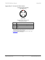
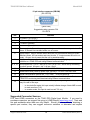
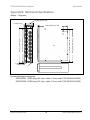
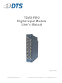
TDAS PRO Digital Input Module User’s Manual March 2015 12000-00020-MAN (Rev. 1) © Diversified Technical Systems, Inc. - All Rights Reserved TDAS PRO DIM User’s Manual March 2015 Table of Contents DTS Support ....................................................................................................................... 3 Introducing the TDAS PRO Digital Input Module............................................................. 4 Overview of TDAS PRO DIM Features .............................................................................. 4 TDAS PRO DIM Connector/LED Panel ........................................................................... 4 Using the Voltage Input ............................................................................................... 4 Using the Contact-Closure Input .................................................................................. 5 Electronic Identification (EID) ...................................................................................... 5 Level Trigger .................................................................................................................... 5 Cable Integrity Verification ............................................................................................... 5 Memory Size .................................................................................................................... 6 Basic Care and Handling ................................................................................................... 6 Shock Rating.................................................................................................................... 6 Thermal Considerations ................................................................................................... 6 Power Management............................................................................................................ 7 Power Consumption ......................................................................................................... 7 Internal Back-up Battery .................................................................................................. 7 Charging the Battery .................................................................................................... 8 Battery Capacity .......................................................................................................... 8 Battery Life Cycle......................................................................................................... 8 Power-up and Power-down Procedures .......................................................................... 8 Communication Features .................................................................................................. 9 Communication Methods ................................................................................................. 9 LED Indicators ................................................................................................................. 9 15-pin Interface Connector (DB15M) ............................................................................. 10 Appendix A: Connector Information.............................................................................. 11 Suggested Connector Sources ...................................................................................... 12 Appendix B: Mechanical Specifications........................................................................ 14 support.dtsweb.com ii 12000-00020-MAN (Rev. 1) TDAS PRO DIM User’s Manual March 2015 DTS Support TDAS systems are designed to be reliable and simple to operate. Should you need assistance, DTS has support engineers worldwide with extensive product knowledge and crash test experience to help via telephone, e-mail or on-site visits. The best way to contact a DTS support engineer is to submit a request through the DTS Help Center web portal (support.dtsweb.com). You must be registered (support.dtsweb.com/registration) to submit a request (https://support.dtsweb.com/hc/enus/requests/new). Registration also enables access to additional self-help resources and non-public support information. This manual supports the following products: 12000-00020: TDAS PRO DIM (Digital Input Module) support.dtsweb.com 3 12000-00020-MAN (Rev. 1) TDAS PRO DIM User’s Manual March 2015 Introducing the TDAS PRO Digital Input Module The TDAS PRO Digital Input Module (DIM) is a standalone, 16-channel digital data acquisition system capable of recording virtually any on/off condition. Each channel is independently programmable for either contact-closure or voltage event signals. Any channel may be programmed for use as a level-trigger for all modules in a single TDAS PRO rack system. Event signals are easily connected via LEMO connectors on the front panel. TDAS PRO DIMs may be used side-by-side with other TDAS PRO modules including Sensor Input Modules (SIMs) and Timed Output Modules (TOMs). Overview of TDAS PRO DIM Features Built and tested for 100 g dynamic testing environments. Sixteen fully-isolated contact-closure or voltage event channels. Self-powered contact-closure event inputs. Voltage event input range of 3-15 V. Electronic identification (EID) support. Internal back-up battery with a capacity of ~10 minutes for safe operation even with loss of primary power. Simple 15-pin interface connector for use with TDAS PRO racks and TDAS PLUS Module Interface and Single Module Devices. LED indicators for power and event status. Connector information and pin assignments can be found in Appendix A. Mechanical specifications are included in Appendix B. To identify the specific hardware included with your system, please see your packing list. TDAS PRO DIM Connector/LED Panel Sixteen isolated, protected, and self-powered voltage or contact-closure event digital input channels are available via the LEMO connectors on the front panel. Each channel is independently programmable. See Appendix A for connector information and pin assignments. Using the Voltage Input These inputs are configured as shown below. Operational Parameters Voltage Input support.dtsweb.com Proper polarity must be observed. >3 V = logic one (3-15 V input range; logic compatible). Can be configured as normally high ( ) or normally low ( 4 ). 12000-00020-MAN (Rev. 1) TDAS PRO DIM User’s Manual March 2015 Using the Contact-Closure Input These inputs can be used two ways: semiconductor switch. simple contact closure or via an external Type of Contact Closure Operational Parameters Self powered. Simple Contact Closure (tape switch or other on/off device) No polarity requirement. Can be configured as normally open ( normally closed ( ). External Semiconductor + Switch C = E - ) or Self powered. Proper polarity must be observed. <300 ohms = logic one; >4500 ohms = logic zero; with a current conducting capability of at least 5 mA. Can be configured as normally open ( normally closed ( ). ) or Electronic Identification (EID) Each TDAS PRO DIM input channel supports communication with silicon serial number devices manufactured by Dallas Semiconductor/Maxim Integrated Products. When an ID chip such as the DS2401 is connected to the proper pins on the sensor connector, the TDAS Control software can read these devices and correlate the serial number to channel set-up information stored in a Digital Information File (DIF). (See Appendix A for connector information and pin assignments.) When wiring any device for EID, proper polarity must be observed and cable length should not exceed 9.14 meters (30 feet). Level Trigger Any one channel may be configured as a level-trigger channel via the TDAS Control software. When this channel is triggered, all other modules in the TDAS PRO rack are also triggered. Specifying a level-trigger channel does not prevent the TDAS PRO DIM from responding normally to a hardware trigger. Cable Integrity Verification The TDAS PRO DIM features the ability to check the integrity of the cabling from the module to the event sensor. Using a 10K ohm resistor connected in parallel with the event sensor, the TDAS Control software will test the external signal path for continuity. This feature is turned on or off via the TDAS Control software. 10K Ω Pin 1 Pin 2 9.14 m (30 ft) support.dtsweb.com 5 12000-00020-MAN (Rev. 1) TDAS PRO DIM User’s Manual March 2015 Memory Size Each TDAS PRO DIM contains non-volatile RAM capable of storing up to 2,000,000 samples regardless of the number of channels in use. The maximum available sampling duration is simply the total number of samples available divided by the sampling rate. Sampling duration (seconds) = 2,000,000 / sampling rate (samples/second) Example: 200 seconds = 2,000,000 / 10,000 samples/second Basic Care and Handling The TDAS PRO Digital Input Module is designed to be reliable and simple to operate. Though resistant to many environmental conditions, care should be taken not to subject the unit to harsh chemicals, submerge it in water, or drop it onto any hard surface. WARNING: Electronic equipment dropped from desk height onto a solid floor may experience as much as 10,000 g. Under these conditions, damage to the unit is likely. When transporting the unit, treat it as you might a laptop computer and you should have no problems. When not in use or if shipping is required, we suggest that you always place the unit in the padded carrying case originally provided with your system. TDAS PRO equipment is not user-serviceable and should be returned to the factory for service or repair. Shock Rating All crashworthy TDAS PRO equipment is rated for and fully tested to 100 g, 12 ms duration, in all axes and can be mounted directly on a vehicle, sled or other dynamic testing device. All modules should be bolted securely to the rack and rack mounting methods and bolt selection should be carefully calculated so as to withstand expected shock loading and facilitate proper grounding. (See Appendix B for the module’s mechanical specifications.) Thermal Considerations TDAS PRO systems use extensive power management to minimize heat generation. Since the system draws the most power when armed, running the calibrations and arming as late as possible will minimize self-heating. It is extremely unlikely that excessive heat will ever be an issue in real-world testing applications using TDAS PRO systems. However, if high ambient temperatures, exposure to other heat sources, or severely restricted airflow will cause case temperatures in excess of 50°C (too hot to touch comfortably), the airflow created by a small fan will increase heat transfer by a factor of 3 to 5. Additionally, always shield the units from exposure to direct sunlight. support.dtsweb.com 6 12000-00020-MAN (Rev. 1) TDAS PRO DIM User’s Manual March 2015 Power Management A good power source is of paramount importance. Each TDAS PRO module should be powered from either: 1) A fully-charged 12 V battery with sufficient capacity for the application, or 2) A high-quality 12-15 V (13.8 V nominal) power supply with a current rating of at least 1 amp for each module and rack in use. DTS-supplied power supplies and distribution units are designed to meet all criteria for proper charging and operation. If you need help determining which set-up is best for your application or if a power supply or charger will meet the power demands, please contact DTS. When installing power supply systems, always consider voltage drops that may occur due to cables, connectors, power converters, etc. DTS does not recommend performing tests using TDAS PRO equipment without the use of an external power source. Power Consumption Power off: When connected to sufficient external power, a TDAS PRO module will draw up to 25 mA to charge its internal back-up battery. A TDAS PRO rack will draw ~600 mA. Power on: When a TDAS PRO DIM is initially powered, all signal conditioning electronics are in a shutdown state. The processor and support circuitry are always powered. The processor will remain in a reduced power state when not performing tasks. When the user runs a test set-up, the software automatically energizes the excitation sources and other circuits. The current draw per DIM will increase to as much as 250 mA when the system is fully armed; current draw for each rack will increase to as much as 900 mA. During data collection: Once the system has been armed for data collection, all circuits remain in a full power state until the system finishes storing data. After the data collection routine is complete, the system de-energizes several circuits to minimize power consumption. It takes a maximum of 20-30 seconds after the end of the data storage window for the system to return to the idle state, which then allows communication and download. Internal Back-up Battery In a typical testing environment, the internal back-up battery is used only in the event primary power is lost. To ensure a smooth transition from external to internal power, each TDAS PRO module contains a 9.6 V, 120 mA, NiCad battery sufficient to sustain full power operation for a short time (~10 minutes when fully charged). DTS does not recommend performing tests using TDAS PRO equipment without the use of an external power source. support.dtsweb.com 7 12000-00020-MAN (Rev. 1) TDAS PRO DIM User’s Manual March 2015 Charging the Battery The internal back-up battery is automatically charged whenever 12-15 V external power is connected to the module. (The BAT LED remains off when the unit is charging but not powered up.) This can be accomplished via a TDAS PRO rack, TDAS PLUS Module Interface Device (MID) or TDAS PLUS Single Module Device. The module should be charged for several hours before testing—overnight works well. The module does not need to be turned on in order to charge the battery. When a module is installed in a TDAS PRO rack, the module’s back-up battery is automatically charged whenever the rack’s smart-charge feature is activated (13.2-15 V is applied to the rack’s main power input). The rack does not need to be turned on in order to charge the module batteries. When a module is connected to a TDAS PLUS MID, the module’s back-up battery is automatically charged whenever the MID is connected to AC power via the MID power supply. The MID does not need to be turned on in order to charge the module’s battery. When a module is connected to a TDAS PLUS Single Module Device, the module’s backup battery is automatically charged whenever the single module device is connected to AC power via the single module device power supply. When connected to a single module device, the module will automatically power-up; there is no power off condition when a single module device is connected to the module. The battery will still charge even if the module is in a power-up condition. Battery Capacity Should external power be lost, the actual useful battery capacity will depend upon the number of channels in use and whether or not the battery was fully charged before testing. When fully charged, the internal battery will provide at least 10 minutes of operational power when fully armed. Battery Life Cycle Charging practices can affect the useful operational life of the internal back-up battery. For example, a battery that is used for short periods but never properly charged will have a relatively short life. Conditioning the battery may be useful; three deep-discharge/recharge cycles may help increase battery performance. The usable period for the battery is greatly shortened near the end of its service life and should be replaced when its capacity has decreased to 50% of its initial capacity. The battery is not user-serviceable; the unit should be returned to the factory for battery replacement. (Note: Factory calibration service includes the replacement of the battery if necessary.) Power-up and Power-down Procedures TDAS PRO modules are powered up when the proper signal is connected at the 15-pin interface connector. This is typically accomplished via a TDAS PRO rack, TDAS PLUS MID or TDAS PLUS Single Module Device. The absence of the same signal will turn off the module unless it is armed for data collection, in which case it will remain on until the module is disarmed or power reserves are exhausted. Power-up of the module takes support.dtsweb.com 8 12000-00020-MAN (Rev. 1) TDAS PRO DIM User’s Manual March 2015 ~5 seconds after which time communication is enabled. Powering down a module takes ~30 seconds. Before restarting a module, wait until all module LEDs go completely dark and then wait 10 seconds more to be sure. An incomplete power-down/power-up cycle can result in errors, so be certain to follow proper procedures. CAUTION: Unless the rack, MID, or single module device is connected to external power, the module will power-up using back-up battery reserves. Communication Features Communication Methods Either RS232 (serial) or Ethernet communication methods are possible given the proper hardware and cables. Ethernet communications are only possible via a TDAS PRO rack. RS232 communications are available via a TDAS PLUS MID or TDAS PLUS Single Module Device. Communication is enabled after the power-up sequence has completed (~5 seconds). Please see your packing list for the cables provided with your system to determine what communication options you have. LED Indicators The TDAS PRO DIM has two LEDs: BAT (blinking red/yellow/green) and T=0 (red). The BAT LED provides ongoing power status only when the module is powered up and communicating. LED Status Battery Voltage Green >8.6 V Yellow 8.4 V – 8.6 V Red ≤8.3 V Please pay close attention to the BAT LED as it will indicate if the power is acceptable (green), low (yellow) or at a critical level (red). WARNING: Do not perform any critical tests when the BAT LED indicator is yellow (power low) or red (power critical). In general, the T=0 LED identifies when a module has received a trigger. Post-test, a download-related command received by the module will cause the T=0 LED to go dark. support.dtsweb.com 9 12000-00020-MAN (Rev. 1) TDAS PRO DIM User’s Manual March 2015 Additionally, it will also light at initial power-up and go dark after a successful power-up sequence. 15-pin Interface Connector (DB15M) All TDAS PRO module functions are controlled through the DB15M connector. It is through this connector that TDAS PRO racks, TDAS PLUS MIDs and TDAS PLUS Single Module Devices power the module and transmit and receive all signals. See Appendix A for connector information and pin assignments. WARNING: Do not apply external voltages to the event, communication, status or control output and inputs—this could result in damage to the unit. Please contact DTS for assistance in properly connecting interface wiring to TDAS PRO modules. DTS offers several interface devices that are specifically designed to connect modules in various ways. support.dtsweb.com 10 12000-00020-MAN (Rev. 1) TDAS PRO DIM User’s Manual March 2015 Appendix A: Connector Information 4-pin front panel connectors (ECG.0B.304.CLL) 1 4 2 3 (panel view) Suggested cable connector P/N: FGG.0B.304.CLADxx** Pin 1 2 3 4 Function (+) Contact closure*/+ voltage (external) (-) Contact closure*/- voltage (external) + ID - ID * No polarity requirement for simple contact closure (tape switch or other on/off device), however proper polarity must be observed when using an external semiconductor switch. ** xx denotes diameter of cable to be used; e.g., 52 = 5.2 mm. See www.lemo.com for more information. support.dtsweb.com 11 12000-00020-MAN (Rev. 1) TDAS PRO DIM User’s Manual March 2015 15-pin interface connector (DB15M) (D3-15PTES) 5 10 15 1 6 11 (panel view) Suggested mating connector P/N: D3-15STS Pin Function 1 + Power in (12-15 VDC) 2 + Power in (12-15 VDC) 3 – Power in (ground) 4 – Power in (ground) 5 Turn-on signal. Connect to power ground to turn module on. Leave open to turn off. Has a 15 second time constant before turn off occurs. 6 Status output. Used to indicate status while the unit is armed and waiting for event. Monitors power, A/D conversion and event circuits. 5 V output means the unit is not ready. An open circuit means that the unit is armed/recording. 7 High-speed data transfer clock output. Used for synchronizing high-speed data transfers to a TDAS PRO rack using Ethernet communication. 8, 9, 10 Slot program bits. Pin 10 = bit0; pin 9 = bit1; pin 8 = bit2. Active low by connecting to power ground. All open = slot 1; all low = slot 8. 11 Serial communication transmit line. 0-5 V UART. 38.4K on power-up. 12 Redundant memory back-up power input, typically 3.3 V from TDAS PRO rack. 13 Serial communication receive line. 0-5 V UART. 38.4K on power-up. 14 High-speed data transfer output. Used to quickly transfer collected data files to a TDAS PRO rack during data download using Ethernet communication. Event (T=0). Logic low or contact closure with respect to power ground. This input may be used in two ways: - In circular buffer mode, this input actually initiates storage of data AND is used to mark zero time (T=0). - In recorder mode, this input is used to mark T=0 only. 15 Suggested Connector Sources DTS uses LEMO connectors on the TDAS PRO Digital Input Module. If you need to purchase connectors, we suggest first going to LEMO directly (www.lemo.com). Their web site and worldwide sales team are very helpful. Should you have difficulty obtaining a specific part number, they can suggest connector variations or alternates and explain support.dtsweb.com 12 12000-00020-MAN (Rev. 1) TDAS PRO DIM User’s Manual March 2015 options that may be useful for your particular application. Another U.S. source is Alpine Electronics (www.alpine-electronics.com) in San Jose, California. They are a stocking distributor for LEMO and LEMO-compatible connectors. DTS also uses industry-standard D-sub connectors manufactured by Northern Technologies on the TDAS PRO DIM. If you need to purchase connectors, there are many distributors for these and compatible D-sub connectors including Digi-Key (www.digikey.com), Allied (www.alliedelec.com) and Newark (www.newark.com). Contact information for Northern Technologies distributors can be found at www.northerntech.com. support.dtsweb.com 13 12000-00020-MAN (Rev. 1) TDAS PRO DIM User’s Manual March 2015 Appendix B: Mechanical Specifications Weight: 740 grams 1.37 inches/34.67 mm 1 inch/25.4 mm 4.89 inches/124.21 mm 5.46 inches/138.684 mm 5.30 inches/134.62 mm 5.55 inches/140.97 mm 5.80 inches/147.32 mm 0.144 inches diam 3.66 mm diam Accessories/support equipment: 80000-02067: LEMO plug; 0B, 4-pin, solder, 3.5 mm collet (FGG.0B.304.CLAD35) 80000-02068: LEMO plug; 0B, 4-pin, solder, 5.6 mm collet (FGG.0B.304.CLAD56) support.dtsweb.com 14 12000-00020-MAN (Rev. 1) TDAS PRO DIM User’s Manual March 2015 Revision History Rev Date By 1 11 Mar 2015 EK Revised format and boilerplate material. Removed references to LAB DIM. 0 30 Mar 2006 EK Initial release. support.dtsweb.com Description 15 12000-00020-MAN (Rev. 1)