1
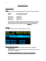
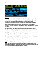
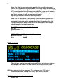
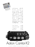
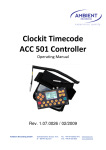
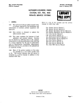
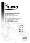
1
CLOCKIT LANC LOGGER
ALL601
Description and instructions for use
Rev. 1.01
Ambient Recording GmbH, Schleissheimer str 181c, D-80797 Munich, Germany
interstage
Phistersvej 31, 2900 Hellerup, Danmark
Telefon 3946 0000, fax 3946 0040
www.interstage.dk
- pro audio with a smile
2
USER MANUAL „LANC LOGGER” ALL601
The Lanc logger is a very small hand held timecode device for use in
Film or TV. Its innovative timecode features makes it an ideal timecode
source, logger and timecode conversion unit when working with DV and
HDV cameras and computer based audio recorders with and without a
timecode input/output. The LANC LOGGER can offer solutions both on
location and in Post production.
Timecode source with 0.2 ppm accuracy from Ambient Clockit XTAL Ref.
The LANC LOGGER is a Clockit device and the VCTCXO Xtal reference
can be calibrated to an accuracy of under 0.2 ppm relative to other
Clockit units such as the Lockit box and the Controller. Timecode drift
between boxes is well under 1 frame a day. A new IR port allows the
device to be set with Timecode and offset checked, without cables, using
the Aaton ASCII Protocol and the Controller ACC501.
Using the Standard TC Lemo 5 pin interface socket with TC in, TC out,
Tuning and ASCII port, the ALL 601 is fully compatible to all portable
timecode equipment including the Aaton Origen C unit.
The audio port with timecode as a burst or as a continous signal with
adjustable timecode levels –55dB to 0dB (1mV to 0.5 Volt ) and with
additional –20dB pad, allows connection to all camera audio inputs
using Minijack or Cinch connectors, without overload and crosstalk
Timecode logging from various sources. LANC, MIDI, LTC, Manual
The LANC LOGGER is fitted with a 512 MB flash card and can write logs
into this memory. Complex logs for use in Post production can be made,
using camera start/stop signals, and the Record Run (Rec.Run.)
timecode of the cassette from the LANC port of a Sony camera and
logging to its accurate internal time of day (TOD). The LTC out of a
camera can be used as Rec. Run. timecode source. The logger analyses
the timecode and only logs when the camera is in record, not in playback
or when spooling. Events can be Logged manually to TOD and given a
value using the keys with ASCII symbols. The ALL is a mass storage
device and the logs can be downloaded to a computer is via USB. The
logs can be converted to a EDL using the CB EDL master Program.
Timecode conversiom
With the increasing use of a computer and USB audio hardware for
portable recording or playback, the timecode conversion features in the
ALL can be very useful. The following conversions are possible.
3
Conversions
LANC TC
LANC TC
EXT LTC
EXT LTC
INTERN GEN TC
MIDI TC (USB)
EXT LTC
to
to
to
to
to
to
to
MIDI TC (USB Port) and LTC (Lemo, Audio)
LTC with or without OFFSET
MIDI TC (USB Port)
LTC with or without OFFSET
MIDI TC (USB Port) MIDI
LTC with or without OFFSET
LTC with or without OFFSET
Uses
• A laptop computer is being used as an audio playback or recording
device. The Playback TC is available as a MIDI Timecode. The ALL is
connected to the USB port of the computer and converts the MIDI TC to
LTC for transmission to a timecode slate etc.
•
A film camera is connected to an editing System (FCP, Avid Express) to
digitalise the cassette. The LANC TC can be converted and transferrerd
to the computer via MIDI TC or LTC. LTC on an audio track of the camera
can be converted to MIDI TC and sent to the computer via USB.
•
The internal Generator TC of the ALL (TOD) can be used as timecode
source (via MIDI) for a computer recording Audio.
4
DEVICE DESCRIPTION
IR Comms
Mic/Audio
TC out to Camera
Mic/ Audio
TC/ Mic in
Lanc to
Remote
Lanc from
Camera
USB
ESC / Enter
Command Keys
Batteries
Cursor Keys
ALL 601
Display
PORTS AND
ACCESS
Lemo: Aaton, Ambient TC Interface
AUDIO INTERFACE AND LTC INPUT OUTPUT
The audio interface ist a two channel unbalanced input/output with
Electret power supply (5.6Volt) on channel 1 of the input, switchable
LTC out on channel 2 output, and an auxiliary LTC input on channel 1
(when the mike is not being used).
The LTC level can be adjusted from 0db to –55db with an extra –20db
switched pad at the LTC output to audio, allowing LTC input to every
type of microphone or line input without distortion or crosstalk. On
channel 1 at the mike side is a switchable Powering of 5.6 volts that
covers the requirements of all Electret microphones.
The LTC ouput on channel 2 can be set to either off, continous ,or burst,
(triggered by the record on signal from camera LANC), allowing audio to
be recorded on channel 2 aftewr the burst.
•
•
•
•
Electret Mike power supply
LTC output with adjustable levels,
LTC switchable as burst, continuous, or off
LTC auxiliary input
5
Uses
Audio track LTC recording
To record the exact TOD (Userbits inserted from Logger) of the ALL to an
audio track of the camera being used, thus allowing this timecode to used
in post production to sync sound and picture.
Note: Recording Audio track LTC can be done simultaneously to logging
Burst LTC
LTC can be recorded at the beginning of a take for 1 second, using the burst
LTC triggered by the camera start/stop info from the LANC or external TC
input. After this the Audio channel is free for audio recording ( 2 channel
audio with Timecode)
Logging using Aux. TC input .
Using an external Rec.Run. LTC to make a log against ALL internal TOD.
Internal timecode software filters and checks the LTC in signal and only
makes a log when the camera is in record. Spooling or shot playback
timecode does not trigger a log.
LANC INTERFACE
The ALL’s LANC interface can read the LANC signal of a Sony** camera
and the through output allows a zoom control to still be connected to the
camera via the ALL. The ALL takes its powering from the LANC socket,
Note:Available current at the camera LANC socket is about 70mA at 5
Volts. The ALL takes 50 mA. Leaving 20 mA for a zoom control, this is as
adequate for most zoom controls but can lead to malfunction if more
than 15mA is used.
Alternative powering is through the Lemo socket with 6 to16 Volts
voltage range.
** other manufacturers using the Sony LANC protocol (Canon) do not
adhere to the Sony protocol. Neither the message framerate nor
timecode values are ouputted correctly. The ALL can only read the
LANC from Sony cameras. Panasonic control M is only suitable for
remote zoom connection and does not output Rec.Run. timecode values
as does the Sony LANC.
LANC Signals read
Camera start stop
Rec.Run. Timecode
Any other available data that could be useful to log
TIMER
The ALL can be used to start and stop the camera at specific TODs
allowing remote start and stop, for example slow motion shots**.
**Not yet implemented
6
Uses
LOGGING. The ALL makes logs of Rec.Run. Timecode from the LANC
out of the camera gainst internal TOD. Ancilliary data such as cassette
number, camera ID, (entered manually to the ALL), and Event Number,
(automatically incremented) and RTC date and time are also recorded in
the log. Log format is open so that future extensions and IXML
conformity are possible. The TOD Timecode with the ancilliary data in
the Userbits can be simultaneously recorded on a camera audio track.
thus giving a second method of syncing audio and picture.
The logs are stored on a built in 512MB flash card and can be
downloaded through the USB port to any computer. They can then be
converted to an EDL using the CB EDL master program which can then
be used to sync the sound and video to a TOD timeline.
A complete solution for FCP is being developed by Andreas Kiel of
Spherico com.
USB PORT
The USB port is configured as a USB audio device and can be connected
to any computer with a USB port.
Uses
External power supply of the ALL
MIDI TC input and Output
ALL program updates upload eg from www.ambient.de
Mass storage download of logs
KEYPAD AND IR PORT
On the top of the ALL is are the keypad, display and Infra Red (IR)
windows. In addition, the sockets and battery polarity are indicated.
KEYS
There are 6 keys used to configure the ALL and to call up system data,
Some have additional special functions. A few functions such as
jamming the internal TOD generator from Ext TC or incrementing the
cassette number can be carried out using a quickkey combination.
7
ESCape left, red
In addition to an ESCcape function when navigating the menus, this key
is used to switch the ALL on and off or with the ENTer key to go into a
Standby mode. The lightning symbol symbolises this function.
Switch on: press ESC for 3 seconds
Switch off: press ESC till display shows standby or turn off
Switch off: Press ESC for switch off, or ENTer for standby.
(As in the ACC501)
The ESC key can be used to log events to internal TOD manually. The
ENTer key has the same function in Manual (key) Log mode allowing left
or right handed action. The word LOG in yellow on both keys reminds of
this function.
ENTer Right green
In addition to an ENTer function when navigating and configuring the
menus, this key is used to switch the ALL into Standby.
The ENTer key can be used to log events to internal TOD manually in
Manual Log mode. The ESC key has the same function allowing left or
right handed action. The word LOG in yellow on both keys reminds of
this function.
The ENT key is also used in Quickkey combinations
Switch on: press ESC for 3 seconds
Switch off: press ESC till display shows Standby or turn off
Standby: press ENT for standby. (As in the ACC501)
Four Cursor keys
The 4 cursor keys are situated in an arc under the display window and
are marked with arrows and four ASCII symbols. !#*? These symbols can
be used to describe an event in manual logging mode eg. ! goal, # bad, *
good, ? unusual. The meaning of the symbols is left to the user. They
are stored in the log data and can be used to mark a log.
Primarily the keys are used to navigate and configure the ALL menus ,
In addition, by pressing the 2 inner cursor keys (arrows pointing in) the
ALL can be “locked*” for a job, whereas the outer 2 keys (arrows
pointing up,down) are used to “unlock*” a job.
*No menu changes possible in locked condition.
(unlocked, menu free to configure)
IR WINDOW
The IR transparent window with its TX and RX lenses is in the top middle
of the keypad surface. This port transmits and receives the Aaton ASCII
protocol and can be used to set and error check the TOD timecode
generator in the ALL with the controller ACC 501, without a cable
connection
8
DISPLAY
The Display is a 2 colour ( yellow bar on top, rest blue) OLED with
128X64 pixels. OLED displays are small daylight readable, low power
devices and are ideal for portable equipment. The yellow bar shows the
timecode and userbits and other data of the TOD generator. Then there is
a menu bar with tablike structure. The rest of the display is used for
menu description and selection, and in “job closed” mode for showing
actual data and settings.
LEMO SOCKET
This socket has the same pin allocation as other Ambient clockit units
Pin Function
1
Ground
2
LTC in
3
Aaton ASCII. Tx, Rx
4
Tune signal out 1.92 Mhz. External Power in 6 to 16 volts
5
LTC out
BATTERY COMPARTMENT
The battery compartemnt is situated on the left side and has an anodised
aluminium hinged door containing reverse polarity protection contacts.
Care should still be taken to check correct polarity when inserting
batteries. The door is closed by closing and pushing towards the bottom
side of the ALL. The door moves to a locked position held in place by the
force of the battery springs,
To open, press in and slide the door in the opposite direction to closing.
The door will move back and spring open, shooting the batteries to
various unaccessible places! Be careful this does not happen!!
SPECIFICATION
Interfaces
• Lemo 5 pin interface Ambient /Aaton TC standard
• Battery compartment 2 X AAA with reverse polarity protection
• Two colour OLED display
• Four cursor keys with alternate functions
• Red ESC key with turn on symbol and Log function
• Green ENT key with log and quickkey function
• USB port for program upload, MIDI and Mass storgage download
• Audio in/out (2 heavy duty 3.5mm and 2.5mm minijack sockets*) with
Electret Mike power LTC out on channel 2 (ring of minijack) and LTC in
on channel I (tip of minijack)
• LANC in/out (2 heavy duty 3.5mm and 2.5mm minijack sockets*)
For connection to the LANC port of Sony camera and for simultaneous
connection of remote zoom control
• Infrared port for ASCII protocal comms. between Controller ACC501 and
ALL
* Connection to Lanc and Mike input of prosumer camera ( 2.5mm /
3.5mm Minijack) through universal cable supplied.
9
Hardware Description
• Internal power supply with standby power, from batteries (2xAAA)
• 40 Mhz ARM 7 RISC processor
• 6K non volatile Ferromagnetic memory
• RTC ( Real Time Clock) with backup battery for Time and Date etc
• SD flashcard holder with 512MB flashcard
• In/out inteface electronics for TC, USB, LANC, AUDIO, IRDA, ASCII.
Powering:
• 2 x AAA
• LANC
• USB
• Lemo
3 Volt Internal
5 Volt External
5 Volt External
Pin 4. 5 to 16 Volts max External
Size:
weight:
Power consumption:
75 X 67 X 21mm
120 Gram
150 mW (ca 50 mA bei 3 Volt Batteriespannung )
Accessories
• Protective bag with Velcro backing and display window.
• Universal Minijack as straight or spiral cable, with 2.5mm and 3.5mm
moulded plugs.
• Cables with 3.5mm or 2.5mm moulded plugs and open ends available for
making other connection cables
• TC out cable: Minijack 2.5mm to XLR M for XLR mike input
with 48Volt phantom power protection!!
• TC in cable: Green XLRW 3 Pin auf Lemo 5 Pin
• TC out cable: Red Lemo 5 Pin auf XLR M 3 Pin
• Camera TC jam cable: TC out, camera, BNC, auf TC in, Lemo 5 Pol
10
Instructions or use
General desription
KEYS
There are 6 keys used to configure the ALL and to call up system data,
ESCape
ENTer
( also Log and turn on/off )
( also Log and standby )
Left cursor
Down cursor
Up cursor
Right cursor
( and ascii ! )
( and ascii # )
( and ascii * )
( and ascii ? )
Some keys have additional special functions. A few functions such as
jamming the internal TOD generator from Ext TC or incrementing the
cassette number can be carried out using a quickkey combination.
DISPLAY
The display of the ALL is divided up into 3 sectors.
Source TC bar, top, in yellow
The TOD TC generator Time, Userbits and Framerate is generally
displayed here.
In Convert mode, the Time and other data from the selected source, eg
MIDI, LANC, is displayed.
In principal this block displays the “ Source” Timecode details.
11
JOB/Menu bar in Blue
The JOB bar is configured to look like tabs in a filing system. On the right the
battery capacity (Symbol) and System data menu (SYS) are displayed.
On the left the job tab blinks,
Note: On switch on the job tab is automatically selected and blinking with last
job selected.
The menu and configuration system works in the following way.
The job is selected with ENT to enter the JOB menu, the cursors to select, and
ENTer pressed again. The selected job appears on the far left tab, blinking.
Simultaneously, all the submenus that can be configured for the selected job
appear in the rest of the menu bar to the right of the job tab and can be
selected and configured.
12
Menu Bar
When a menu is selected with ENTter then the Menu select bar appears The
menu title moves to the left position and submenu details to configure, appear
on the right. Submenu details can be selected with left or right cursor and
ENTter. SYS and battery symbols disappear to make room for menu
parameters. ESCape returns to the JOB bar with battery and SYS symbols.
When all menus have been configured, ESCape returns to the JOB bar.
The job is “closed” by pressing the two inner cursor tabs together, ie. “closing
the doors”.
In “doors closed” the JOB tab ceases blinking and no parameters can be
changed, but one can view the parameters selected in the menus by moving to
the menus with the left and right cursor keys. The parameters selected, or
being processed by the ALL are shown under the menu selected.
The JOB can then begin without danger of changing parameters by inadvertent
pressing of the keys.
To change a parameter during a job ie. Cassette number increment, first press
the two outer Cursor keys simultaneously thus “ opening the doors. The JOB
tab will blink and parameters can be changed. Then the doors can be closed.
Always run a job with doors closed.
Note: See LOG job, Mode menu for quickkey cassette number increment.
Note: The job can only be closed when the job bar is shown and the JOB
selected (left) is blinking. Conversely the job can only be opened when the Job
bar is displayed and the Job selected is not blinking!
13
MENU DESCRIPTION
ON OFF Menu
SWITCH ON
Press ESCape for 3 seconds, display will light up and show
AMBIENT CLOCKIT
LANC LOGGER ALL601
Serial Nr...........,
Software version........
After 5 seconds display changes to last selected job and settings with job
open
SWITCH OFF
Press ESC for 3 seconds. Standby window will show
Press ESC to switch off in 3 seconds
Press ENT to enter Standby
Press left cursor to return
Note: In standby all settings are held and the timecode generator continues to
generate accurate timecode. The ALL is in a state of sleep except for the TC
generator and reference oscillator. 2 pixels ( yellow Blue) in top right corner of
the display blink regularly.
14
TO SWITCH ON FROM STANDBY
Press ESC for 3 seconds, wakeup window shows
Press ESC to wake up
Press ENT to reenter standby
Note: to enter menu and change settings press ENT with selected tab, press
ESC to return
JOB DESCRIPTION
TCO. TIMECODE OUT
The ALL is used as an accurate timecode source.
The following menus are activated
GEN. Here all aspects of the generator TC can be set
Extern: Jam source
Edit: time userbits
Fps: Framerate
Preset: RTC or start form zero
Offset. Offset of Auxiliary TC out (AUDio)
AUD (ATC) TC output parameters.
TC offset, +-10 frames
TC level -55dB (Mike level) to 0dB (Line level) in 10 steps to suit the
input.
Output Mode, Off, Burst, or Continuous.
15
SYS system parameters
RTC. The real time clock
Time can be set from the TOD generator or edited
Date can be set from the TOD generator or edited
DISPLAY Parameters
The brightness of the display can be set
Auto off function can be turned on or off.
Note: use a display brightness that is required, not brighter. This
conserves power and prolongs display life.
RED Logging filter and TC spot check can be set (only in logging mode)
INPUT TC FILTER See table
TC SPOT CHECK 5, 7, 10 sec after REC begin
Setting
Record-Run
Record In
Consecutive Frs. 2 to 22 in the
same second.
Incremental
Record Run
Consecutive Frs. 2 to 22 in the
same second.
In addition the following
critera must be fulfilled
• Cassette number has changed
• Timecode value is larger than
the last Rec.Run. time out value
LANC-Status changes from any
status to „rec“
LANC-Status
( “rec” on off
status)
Input High
“Rec” on Off
signal
Input Low
Rec” on Off
signal
Record Out
Same value timecode in 2
consecutive frames
( timecode stopped)
Same value timecode in 2
consecutive frames
( timecode stopped)
LANC-Status changes form
„rec status to any status
Low→High Transition
High→Low Transition
High→Low Transition
Low→High Transition
16
Note: The filter is used to ascertain whether the recording device is in
Record or just spooling or playing back. According to this information a
log is started or not. Use the incremental record run filter for most EXT
LTC recording situations. The lanc status bit Rec / stop can be used to
verify record status using the LANC as Rec. Run. TC source. Input high
and input low are for using a Camera on/off signal.
eg: red light signal to ascertain recording status.
Note: The TC spot check is a spot entry of record run TC against TOD
made at a certain interval after the recording has started. It is used to
extrapolate timecode values at the beginning of a log where Rec. Run.
TC can be incorrect during cassette run up or stopping. Here the spot
check time after log begin can be set.
SYS INFO here the system info is displayed
ALL 601
Serial number…….
Software version…....
MICRO SD Here the Flash card details are shown
Manufactrurer ID: 2
Product name:
SD512
Size:
488 MB
LOG
LOGGING
This job logs external timecode to internal TOD on a flash card and can
also output TOD as Ext LTC with usebits containing cassette, event
number etc
GEN Here all aspects of the generator TC can be set ( see TCO menu)
Framerate, Userbits, startup time offset, jam source, edit, etc.
MODE Here the log mode can be selected
DISABLED
17
LANC to TOD. Using a Sony Lanc port for Rec. Run. timecode source
EXT LTC to TOD Using external Rec. Run. LTC as timecode source
KEY TOD. Using manual keystroke to mark events in TOD
Note: When logging select MODE menu to display incoming data,
cassette number and Box ID.
Note: In this menu, usually shown when Logging, to display log
data, the cassette number can be incremented quickly by using a
quickkey combination. With tab on Mode, open JOB, LOG blinks,
press up cursor then ENT to increment or down cursor then ENT
to decrement cassette number. Then Close JOB to proceed.
AUD (ATC) TC output parameters.
TC OFFSET. +-10 frames
TC LEVEL. -55dB (Mike) to 0dB (Line). 10 steps to suit the input.
OUTPUT MODE. Off, Burst, or Continuous.
UB Log and userbit ID numbers
BOX ID Camera/recording device number
CASSETTE ID cassette number
EVENT NUMBER start number
This number increments with every Log made
OPT option bit, Sets option bit in the log and TOD userbits
SYS system parameters
RTC. The real time clock
time can be set from the TOD generator or edited
date can be set from the TOD generator or edited
DISPLAY Parameters
The brightness of the display can be set
Auto off function can be turned on or off.
Note: use a display brightness that is required, not brighter. This
conserves power and prolongs display life.
18
RED Logging filter and TC spot check can be set ( logging mode)
INPUT TC FILTER See table
TC SPOT CHECK 5, 7, 10 sec after REC begin
Setting
Record-Run
Record In
Consecutive Frs. 2 to 22 in the
same second.
Incremental
Record Run
Consecutive Frs. 2 to 22 in the
same second.
In addition the following
critera must be fulfilled
• Cassette number has changed
• Timecode value is larger than
the last Rec.Run. time out value
LANC-Status changes from any
status to „rec“
LANC-Status
( “rec” on off
status)
Input High
“Rec” on Off
signal
Input Low
Rec” on Off
signal
Record Out
Same value timecode in 2
consecutive frames
( timecode stopped)
Same value timecode in 2
consecutive frames
( timecode stopped)
LANC-Status changes form
„rec status to any status
Low→High Transition
High→Low Transition
High→Low Transition
Low→High Transition
Note: The filter is used to ascertain whether the recording device is in
Record or just spooling or playing back. According to this information a
log is started or not. Use the incremental record run filter for most EXT
LTC recording situations. The lanc status bit Rec / stop can be used to
verify record status using the LANC as Rec. Run. TC source. Input high
and input low are for using an Camera on/off signal, eg red light signal to
ascertain recording status.
Note: The TC spot check is a spot entry of record run TC against TOD
made at a certain interval after the recording has started. It is used to
extrapolate timecode values at the beginning of a log where Rec. Run.
TC can be incorrect during cassette run up or stopping. Here the spot
check time after log begin can be set.
SYS INFO here the system info is displayed
ALL 601
Serial number…….
Software version…....
MICRO SD Here the Flash card details are shown
Manufactrurer ID: 2
Product name:
SD512
Size:
488 MB
19
CON TIMECODE CONVERSION
Converts Timecode source to another TC out format, with or without
offset
MODE sets conversion path
LANC to LTC/MIDI lanc to MIDI and LTC
FRS. Output Framerate of MIDI TC
LTC to LTC/MIDI.
FRS. Output Framerate of MIDI TC
MIDI to LTC
FRS Output Framerate ofLTC
OFS LTC offset für LANC to LTC/MIDI mode.
Offset for Lemo and audio outputs
AUD (ATC) TC output parameters.
TC OFFSET, +-10 frames
TC LEVEL -55dB (Mikelevel) to 0dB (Line level) in 10 steps to suit the
input.
Output Mode, Off, Burst, or Continuous.
SYS system parameters as already shown
20
FDL File download
Use this job when ALL is connected to a computer to download log files.
UPD Program update
USB mass storage upload enable
Press enter to enable mass storage
Then upload new ALL601.bin file from computer. Then change to FLASH
FLASH shows program files on flash
Press enter to update the program. Note program file remains on flash till
higher version is uploaded
SYS system parameters
As above
Chris Price
Ambient Recording GmbH
28 Aug 2007
Ambient Recording GmbH, Schleissheimer str 181c, D-80797 Munich, Germany
Tel:+49896518535, Fax:+49896518558 Email:[email protected].
Internet: www.ambient.de
interstage
Phistersvej 31, 2900 Hellerup, Danmark
Telefon 3946 0000, fax 3946 0040
www.interstage.dk
- pro audio with a smile