1
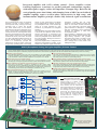
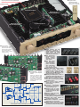
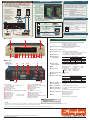
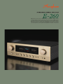
● Revolutionary AAVA volume control ● Output stage with high-power transistors in parallel
push-pull arrangement delivers high quality power: 90 watts x 2 into 8 ohms ● Instrumentation amplifier principle for power amplifier input stage allows fully balanced signal transmission
● Logic-control relays for shortest signal paths ● Strong power supply with massive
high-efficiency transformer and large filtering capacitors ● EXT PRE button allows separate
use of preamplifier and power amplifier sections ● Numeric indication of volume level
Integrated amplifier with AAVA volume control − Power amplifier section
featuring high-power transistors in parallel push-pull configuration, together
with robust power supply, realizes low impedance in output stage. Rated for 90
watts of quality power into 8 ohms, with damping factor of 200. Current feedback
amplifier topology assures excellent phase characteristics in high range, and
instrumentation amplifier principle enables fully balanced signal transmission.
The Accuphase E-200 series of integrated
amplifiers occupies a central position in
the Accuphase lineup, and enjoys enduring
popularity both in Japan and abroad.
The E-260 stands firmly in this tradition,
harnessing the technology advantages of the
series in a new format. It represents a major
overhaul of the E-250, reflecting latest design
technology and featuring the same advanced
AAVA volume control as the higher-ranked
models E-560, E-460, and E-360. The result
is a classy integrated amplifier that brings out
the full musical splendor of every source.
AAVA is a revolutionary principle that
redefines the concept of volume control from
the ground up, operating purely in the analog
domain for high performance and ultimate
sound. Starting with the ultimate, top-of-theline preamplifier C-3800, it has received high
praise as a crucial ingredient for sonic
excellence in preamplifiers and integrated
amplifiers.
The preamplifier and power amplifier sections
of the E-260 are separate circuits that rival
discrete components in performance and
sound. With a simple flick of the EXT PRE
switch, the preamplifier can be detached from
the power amplifier, allowing the sections to
be used individually.
The power amplifier block is configured as an
advanced instrumentation amplifier, which
enables fully balanced signal transmission
throughout. Together with the highly
acclaimed current feedback principle, this
makes for even better electrical characteristics. In the output stage, high-power audio
grade transistors are arranged in a parallel
push-pull configuration which significantly
enhances the capability to safely drive
low-impedance loads.
Output operation is sustained by the power
supply with a massive power transformer and
large filtering capacitors. This provides
high-quality power output of 115 watts x 2 into
4 ohms or 90 watts x 2 into 8 ohms, along
with a damping factor of 200, thanks to the
redesigned circuitry.
AAVA (Accuphase Analog Vari-gain Amplifier) Volume Control
AAVA is a radically different volume control principle that eliminates all variable resistors from the signal path and uses analog processing to provide top-notch performance and sound quality.
Because the music signal is not affected by changes in impedance due to variable resistors, high signal-to-noise ratio and low distortion are maintained at any volume control setting.
■ Volume control resolution
■ AAVA means analog processing
AAVA adjusts the listening volume by means of 16 weighted V-I converter amplifiers
The AAVA circuit converts the music signal from a voltage into a current, controls
which are controlled by current switches. The number of possible volume steps set
gain by means of current switches, and then reconverts the current into a voltage.
by the combination of these converter amplifiers is 2 to the power of 16 = 65,536.
The entire process is carried out in the analog domain.
■ Input buffer amps use 5-MCS topology
■ Same operation feel as a conventional high-quality volume control
One of the factors that have a bearing on possible noise in an AAVA arrangement is the input
Operating the volume knob feels exactly the same as with a conventional control,
buffer design. By connecting five high-performance amps in parallel, excellent S/N ratio is assured.
and as before, operation via the remote commander is also possible.
■ AAVA maintains high S/N ratio and uniform frequency response
■ Attenuator and balance control also implemented by AAVA
AAVA does not introduce a change in impedance at any volume setting.
The functions of the attenuator and the left/right balance control are covered by the
Consequently, there is no deterioration of S/N ratio, and frequency response remains
AAVA circuit as well, eliminating the need for additional circuit stages. Keeping the
totally uniform. The benefits are especially apparent at settings that correspond to
configuration simple helps to maintain high performance and sonic purity.
normal listening levels, because the tonal quality is not altered in any way.
■ Display shows volume level as numeric value
■ No more left/right tracking error or crosstalk
The volume level (degree of attenuation) as set with AAVA is shown as a numeric
Because AAVA is an electronic circuit employing fixed-value resistors, there are
indication in the center of the front panel. The indication ranges from MAX (0 dB) to
virtually no left/right tracking differences even at very low volume levels. Since
MIN (lowest setting).
channels can be kept separate, crosstalk also ceases to be a problem.
16 current switches
(65,536 possible combinations)
AAVA configuration in E-260
1
2
I-V Converter
Reconversion of
current into voltage
1
22
Input music signal
1
23
+Current
BUFFER
INPUT
I-V
OUTPUT
values are
added
5-MCS
LEVEL DISPLAY
1
215
1
216
V- I Converter
Conversion into current
with 16 weighting stages
(1/2 - 1/216)
CPU
AAVA operation principle
The music signal is converted into 16 types of
weighted current by V-I (voltage - current)
converting amplifiers [1/2, 1/22, ... 1/215, 1/216].
The 16 currents are turned on or off by 16
current switches, and the combination of
switch settings determines the overall volume.
The switching operation is controlled by a
CPU according to the position of the volume
control knob. The combined signal current
forms a variable gain circuit that adjusts the
volume. Finally, the combined current is
converted back into a voltage by an I-V
(current-voltage) converter.
Volume
Balance
Attenuator
CPU detects position of volume knob
and operates current on/off switches
according to knob position
Volume knob is turned
and position is detected
■ CPU assembly for control of AAVA
and various other functions
■ AAVA volume control assembly
with higher integration density
of components and circuitry
Logic relay control and line inputs/outputs
Option board slot
Protection circuitry
■ Supplied remote
commander RC-200
Allows volume adjustment
and input source switching
Large power transformer
Massive heat sink
and power amplifier PCB
Preamplifier power
supply PCB
Large filtering capacitors
Massive heat sink
and power amplifier PCB
AAVA volume control PCB
■ Power amplifier
assemblies with parallel
push-pull output stage,
instrumentation amplifier,
and current feedback
amplifier, directly mounted
to large heat sink
■ Instrumentation amplifier
principle in power amplifier
section
Allows fully balanced signal
paths throughout, from input
to output, including signal
input stage. Current feedback
circuit topology ensures outstanding high-range phase
characteristics.
+ B3
+ B2
+
+ B1
Q7
Bias
stabilizer
Q9
Q 11
Q 13
Q5
–
Q1
Q3
NFB
NETWORK
INPUT
OUTPUT
NFB
NETWORK
Bias
stabilizer
NFB
NETWORK
Q2
–
Q4
Q6
+
Bias
stabilizer
Q 10
Q8
Q 12
Q 14
– B1
– B2
– B3
Circuit diagram of E-260 power amplifier (one channel)
■ Power amplifier unit with
high-power transistors in
parallel configuration delivers
ample power: 115 watts/
channel into 4 ohms or 90
watts/channel into 8 ohms.
High-power transistors
■ Hefty high-efficiency
transformer and large
filtering capacitors
(22,000 µF x 2) provide
ample reserves.
■ EXT PRE button
and preamplifier
output/power amplifier
input connectors
allow independent
Large power transformer
Filtering capacitors
use of pre and
power amplifier sections.
■ Option board slot allows system
expansion. Realize digital input
capability (USB, coaxial, optical) or
analog record playback. With
AD-20 board, MC/MM switching on
EXT PRE button
MC/MM selector
E-260 front panel is possible.
■ Redesigned NFB path results in
minimized output impedance and a
damping factor as high as 200.
■ Two sets of large-size speaker
terminals accept Y lugs and enable
speaker bi-wiring.
■ Tone controls using summing
active filters for optimum
Large speaker terminals
sound quality.
■ Loudness compensator
for enhanced sonic impact
at low listening levels.
■ Versatile array of inputs
including balanced inputs
to shut out external noise
interference.
■ Balanced inputs with phase
selection capability.
Line input and output connectors
■ Logic-controlled relays assure high and balanced input connectors
sound quality and long-term reliability.
■ Analog peak power meters for
monitoring output levels.
■ Dedicated headphone amplifier
optimized for sound quality.
■ "High Carbon" cast iron insulator
feet with superior damping characteristics further enhance sound quality.
Highly reliable parts selected for sound quality
Connection example for bi-amping setup
In a bi-amped setup, the speaker units for the
LOW frequency range and HIGH frequency range
are driven by separate amplifiers with equal gain,
for even better sound quality.
Left loudspeaker
Right loudspeaker
− ○
+ ○
+ ○
−
○
HIGH
LOW
RIGHT
− ○
+ ○
+ ○
−
○
HIGH
LOW
LEFT
− +− +
E-260
Digital Input Board
● The
*The speakers must
have a built-in
crossover network and
separate inputs for
LOW and HIGH range.
*The example shows a
setup with an
additional power
amplifier for the low
frequency range.
Option Boards
E-260 provides one
slot for an option board
on the rear panel.
● Option boards can be
used to implement
direct connection of digital
signals for high-quality
music playback, or to
implement high-quality
playback of analog records.
● The Analog Disc Input
Board AD-9/AD-10 can
DAC-30
AD-20
also be used. In this
Photo shows an example for option board installation
case, the MC/MM button
on the front panel of the E-260 has no effect. MC/MM
switching must be performed on the board.
●
COAXIAL: 75-ohm coaxial cable
Sampling frequency 32 kHz - 192 kHz, 24 bit resolution
OPTICAL: Optical fiber cable
Sampling frequency 32 kHz - 96 kHz, 24
bit resolution
● USB:
USB cable (with Type B connector)
Sampling frequency 32 kHz - 96 kHz, 24 bit resolution
●
Analog Disc Input Board
●
(up to 192 kHz/24 bit)
Digital equipment
Digital (S/PDIF) output
MC/MM switching is possible on the front panel of the E-260.
Internal DIP switches control MC input impedance
and subsonic filter on/off.
+ − + −
Analog output
USB cable
To INPUT
CD player
B connector
( withup Type
to 96 kHz/24 bit (
Power amplifier (P-4100, A-35 or similar)
DAC-30
62 dB
Gain:
36 dB
MM Input impedance: 47 kilohms
(up to 96 kHz/24 bit)
RIGHT
Gain:
MC Input impedance: 10/30/100 ohms (selectable)
Optical fiber cable
LEFT
From PRE OUT
AD-20
This board serves for playback of analog records. It
contains a high-performance, high-gain phono equalizer.
●
Coaxial digital
cable
DAC-30
Features a high-accuracy MDS (Multiple Delta
Sigma) ++ type D/A converter for impeccable sound.
The USB port allows connection to a computer with
a downloaded music library for playback of
high-resolution data with optimum sound quality.
Line Input Board
Computer
Connection example for DAC-30
■ Front panel
LINE-10
This option board provides an additional set of
unbalanced line inputs.
E-260 Guaranteed Specifications
q
w
e
[Guaranteed specifications are measured according to EIA standard RS-490.]
● Continuous Average Output Power (both channels driven, 20-20,000 Hz)
115 watts per channel into 4 ohms
105 watts per channel into 6 ohms
90 watts per channel into 8 ohms
● Total Harmonic Distortion (both channels driven, 20-20,000 Hz)
0.05% with 4 to 16-ohm load
● Intermodulation Distortion 0.01%
r
tyu i
o
!1
!0
!2 !3 !4 !5
● Frequency Response
HIGH LEVEL INPUT/POWER INPUT
20 - 20,000 Hz +0, -0.2 dB (for rated continuous average output)
3 - 150,000 Hz +0, -3.0 dB (for 1 watt output)
● Damping Factor
200 (For rated output with 8-ohm load, 50 Hz)
● Input Sensitivity,
Input Impedance
!6 !7
Input
HIGH LEVEL INPUT
BALANCED INPUT
POWER INPUT
■ Rear panel
Option board
installation slot
!8
!9
@0 @1
@2
Input sensitivity
Input
For rated output For 1 W output (EIA) impedance
134 mV
134 mV
1.07 V
14.2 mV
14.2 mV
113 mV
20 kilohms
40 kilohms
20 kilohms
● Output Voltage,
Output Impedance
PRE OUTPUT: 1.07 V, 50 ohms
(at rated continuous average output)
● Gain
HIGH LEVEL INPUT → PRE OUTPUT : 18 dB
POWER INPUT
→ OUTPUT:
28 dB
● Tone Controls
Turnover frequency and adjustment range
BASS:
300 Hz ±10 dB (50 Hz)
TREBLE: 3 kHz ±10 dB (20 kHz)
● Loudness Compensation +6 dB (100 Hz)
@4 ★
@3
q Input selector
LINE 3 / LINE 2 / LINE 1 / CD-BAL / CD
TUNER / OPTION
w Peak power meters
e Volume level indication
r Power switch
t Preamplifier/Power amplifier separator (EXT PRE)
y Phase selector
u Mono/Stereo selector
i Speaker selector
OFF / A / B / A+B
o Recorder selector
OFF / ON / PLAY
!0 Balance control
!1 Bass control
!2 Treble control
!3 Tone control ON/OFF button
!4 Loudness compensator ON/OFF button
!5 MC/MM selector
!6 Attenuator ON/OFF button
!7 Headphone jack
!8 Line inputs
TUNER / CD / LINE 1, 2, 3
!9 Recorder inputs and outputs
@0 Preamplifier outputs
@1 Power amplifier inputs
@2 Left/right speaker output terminals (2 sets, A/B)
@3 CD inputs (balanced)
@4 AC power connector ★
● Attenuator
−20 dB
● Signal-to-Noise Ratio
Input shorted (A weighting)
S/N ratio at rated output
HIGH LEVEL INPUT
105 dB
BALANCED INPUT
91 dB
POWER INPUT
122 dB
Input
EIA S/N
95 dB
94 dB
101 dB
● Power Level Meters
Logarithmic compression, peak reading meters, output dB/% scale
● Load Impedance
4 - 16 ohms
● Stereo Headphones
Suitable impedance: 8 ohms or higher
● Power Requirements
AC 120 V/220 V/230 V 50/60 Hz (Voltage as indicated on rear panel)
● Power Consumption
49 watts idle
245 watts in accordance with IEC 60065
● Maximum Dimensions Width 465 mm (18-5/16")
Height 151 mm (5-15/16")
Depth 420 mm (16-1/2")
● Mass
20.0 kg (44.0 lbs) net
26.0 kg (57.3 lbs) in shipping carton
■ Supplied accessories:
● AC power cord
● Remote commander RC-200
Remarks
★ This product is available in versions for 120/220/230 V AC. Make sure that the voltage shown on the rear panel matches the AC line voltage in your area.
★ 230 V version has an Eco Mode that switches power off after 120 minutes of inactivity.
★ The shape of the AC inlet and plug of the supplied power cord depends on the voltage rating and destination country.
●
Specifications and design subject to change without notice for improvements.
http://www.accuphase.com
K1205Y PRINTED IN JAPAN
850-2176-00(B1)