1
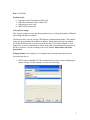
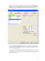
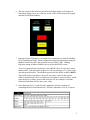
HG3F or HG4F Screen Modbus TCP/IP
Communication and Control of an Emerson Drive
Date: 10/01/2006
Products used:
• Emerson Control Techniques Unidrive SP
• SM Ethernet module for the Unidrive SP
• Ethernet cross-over cable
• IDEC HG4F touchscreen
Notes prior to setup:
This setup procedure assumes that the programmer has a working knowledge of Ethernet
networking and address methods.
The Emerson drive uses an auxiliary SM Ethernet communication module. This module
comes pre-programmed with an Ethernet address, Subnet mask and Gateway address.
For further details on this card, please consult the drives User Guide Manual or Tech
Support for your drive manufacturer. Please ensure that you understand the operation of
the drive and have it wired according to the Users Manual. Please follow all Safety
precautions.
Setup procedure (For simplicity, our example shows communication between one
screen and one drive):
1. HG4F setup for Modbus TCP/IP communication is chosen when configuring the
project settings. For this example, we chose the following:
2
2. Clicking “Next” will bring up the Pop-up tool box. Select the Communication
Interface tab. The TCP/IP address, Subnet mask and Gateway were set as shown
for our drive. Again, consult the drive manuals for proper setup parameters.
3. Next select the Host Port Extension tab. The driver for the HG4F was chosen as
a Server. This gives the option to set the devices on the Ethernet network, which
we want to communicate with.
In the example, we filled the table with the TCP/IP address of our drive. If there
are different drives, we would have a corresponding number of different addresses
to a maximum of four.
3
4. After downloading this screen data, the HG4F screen is now fully programmed to
communicate with the drive.
5. With help from your Drive supplier, configure an HG screen to test control of the
drive.
4
6. The test screen for this trial used one Numerical Data display, one Numerical
Data Entry display (set to use a Pop Up screen #3001 for the Numerical keypad)
and three Word Write Buttons.
7. Emerson Control Techniques overlaid the drives parameter set with the Modbus
RTU Data Register Range. When reading and writing data information using the
Modbus Protocol the drive data locations are specified as “HR”: Holding
Registers staring at address 400000 (also as seen in the HG4F screen).
To access a particular drive parameter such as #X.Y (where X is the drive menu
number and Y is the parameter number) we will use parameter 1.21 (which is the
selected speed reference). The Modbus equivalent in the HG4F would be 400121.
The period used as a separator is not used. Any value written to this register,
which is outlined in the drive User Manual as a legitimate speed reference, would
cause the drive to change speed to that reference. In our example we used the
Numerical Data Entry tool to enter a new value.
8. In the Emerson Drive, a control word is supplied to provide a method of
controlling the drive functions directly. This drive parameter is #6.42, as shown.
5
9. Each bit of the control word corresponds to a function in the drive. The table
below (which is from the drives manual) gives a detailed explanation of the
functions.
10. In our example we configured the three Word Write buttons on our screen in the
HG4F to perform the following tasks by writing data to Modbus address 400642.
a. Writing 193 will STOP the drive
b. Writing 195 will run the drive FORWARD
c. Writing 201 will run the drive REVERSE
11. Please take special note of bit #7 in the control word. This bit must be high for
the control action to take effect.
6