1
ESP6000
Motion Controller/Driver
UNIDRIVE6000
USER’S MANUAL
ESP6000 UNIDRIVE6000
Motion Controller/Driver
USER’S MANUAL
i
Warranty
Newport Corporation warrants this product to be free from defects in
material and workmanship for a period of one year from the date of shipment. If found to be defective during the warranty period, the product will
either be repaired or replaced at Newport’s option.
To exercise this warranty, write or call your local Newport office or representative, or contact Newport headquarters in Irvine, California. You will
be given prompt assistance and return instructions. Send the instrument,
transportation prepaid, to the indicated service facility. Repairs will be
made and the instrument returned, transportation prepaid. Repaired
products are warranted for the balance of the original warranty period, or
at least 90 days.
Limitation of Warranty
This warranty does not apply to defects resulting from modification or
misuse of any product or part. This warranty also does not apply to fuses,
batteries, or damage from battery leakage.
This warranty is in lieu of all other warranties, expressed or implied,
including any implied warranty of merchantability or fitness for a particular
use. Newport Corporation shall not be liable for any indirect, special, or
consequential damages.
First Printing October, 1997
Copyright 1997 by Newport Corporation, Irvine, CA. All rights reserved.
No part of this manual may be reproduced or copied without the prior
written approval of Newport Corporation.
This manual has been provided for information only and product specifications are subject to change without notice. Any changes will be reflected in
future printings.
© 1997 Newport Corporation
1791 Deere Ave
Irvine, CA 92714
(714) 863-3144
P/N 22945-01, Rev. C
IN-04971 (1-98)
i i
EC DECLARATION OF CONFORMITY
We declare that the accompanying product, identified with the
"
" mark, meets the intent of the Electromagnetic Compatibility
Directive, 89/336/EEC and Low Voltage Directive 73/23/EEC.
Compliance was demonstrated to the following specifications:
EN50081-1 EMISSIONS:
Radiated and conducted emissions per EN55011, Group 1,
Class A
EN50082-1 IMMUNITY:
Electrostatic Discharge per IEC 1000-4-2, severity level 3
Radiated Emission Immunity per IEC 1000-4-3, severity level 2
Fast Burst Transients per IEC 1000-4-4, severity level 3
Surge Immunity per IEC 1000 4-5, severity level 3
IEC SAFETY:
Safety requirements for electrical equipment specified in
IEC 1010-1.
Alain Danielo
Jeff Cannon
VP European Operations
Zone Industrielle
45340 Beaune-la-Rolande, France
General Manager-Precision Systems
1791 Deere Avenue
Irvine, CA USA
iii
Table of Contents
Warranty ................................................................................................................ ii
EC DECLARATION OF CONFORMITY ................................................................ iii
List of Figures ....................................................................................................... ix
List of Tables ....................................................................................................... xii
Section 1 — Introduction␣ ...................................................................... 1-1
1.1
1.2
1.3
1.4
Scope .................................................................................................... 1-1
Safety Considerations ........................................................................ 1-2
Conventions And Definitions ............................................................ 1-3
1.3.1 Definitions and Symbols ........................................................ 1-3
1.3.2 Terminology ............................................................................. 1-5
System Overview ................................................................................ 1-6
1.4.1 Features .................................................................................... 1-7
1.4.2 Specifications .......................................................................... 1-8
1.4.2.1 ESP6000 Controller Card........................................... 1-8
1.4.2.2 UniDrive6000 Universal Motor Driver..................... 1-9
1.4.2.3 Environmental Limits ................................................ 1-9
Section 2 — System Setup␣ ..................................................................... 2-1
2.1
2.2
2.3
2.4
Unpacking ............................................................................................ 2-1
PC Hardware and Software Requirements ...................................... 2-2
Equipment Controls and Indicators ................................................ 2-2
Installation and Connection .............................................................. 2-5
2.4.1 Installing the ESP6000 Controller Card and
Software Driver ....................................................................... 2-5
2.4.2 Installing Windows Software ................................................. 2-9
2.4.3 Verifying Communication Between the ESP6000 Card
and the PC .............................................................................. 2-15
2.4.4 Selecting The UniDrive6000 Line Voltage .......................... 2-16
2.4.5 Connecting Stages ................................................................. 2-18
2.4.6 Connecting the UniDrive6000 to the
ESP6000 Controller Card ...................................................... 2-19
Section 3 — Quick Start␣ ......................................................................... 3-1
3.1
3.2
3.3
3.4
3.5
General Description ........................................................................... 3-1
Motor On .............................................................................................. 3-1
Homing a Stage ................................................................................... 3-3
Jog ......................................................................................................... 3-4
System Shut-Down .............................................................................. 3-6
Section 4 — Windows Utilities␣ ........................................................... 4-1
4.1
iv
Motion Utility ...................................................................................... 4-1
4.1.1 General Description ................................................................ 4-1
4.1.2 Features .................................................................................... 4-1
4.2
4.1.3 Operation ................................................................................. 4-1
4.1.3.1 File Menu .................................................................... 4-3
4.1.3.1.1
Reset System ......................................... 4-3
4.1.3.1.2
Save ........................................................ 4-3
4.1.3.1.3
Advanced ............................................... 4-3
4.1.3.1.4
Demo Mode ........................................... 4-3
4.1.3.1.5
Exit .......................................................... 4-4
4.1.3.2 Setup Menu ................................................................ 4-4
4.1.3.2.1
Motion .................................................... 4-5
4.1.3.2.2
Faults ...................................................... 4-7
4.1.3.2.3
Hardware ............................................... 4-8
4.1.3.2.4
Firmware .............................................. 4-11
4.1.3.2.5
UniDrive ............................................... 4-11
4.1.3.3 Motion Menu ............................................................ 4-12
4.1.3.3.1
Stop ...................................................... 4-12
4.1.3.3.2
Home .................................................... 4-12
4.1.3.3.3
Jog ......................................................... 4-12
4.1.3.3.4
Cycle ..................................................... 4-12
4.1.3.3.5
Enable ................................................... 4-13
4.1.3.4 Status Menu .............................................................. 4-13
4.1.3.4.1
Position ................................................ 4-14
4.1.3.5 Help Menu ................................................................ 4-14
4.1.3.5.1
About ESP 6000 ................................... 4-15
Servo Tuning Utility ......................................................................... 4-15
4.2.1 General Description .............................................................. 4-15
4.2.2 Features .................................................................................. 4-15
4.2.3 Operation ............................................................................... 4-15
Section 5 — Programming␣ .................................................................... 5-1
5.1
5.2
5.3
5.4
Table of Contents
General Description ........................................................................... 5-1
5.1.1 Windows Programming .......................................................... 5-1
5.1.2 How To Use The Dynamic Link Library ............................... 5-1
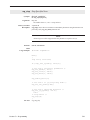
Description of Commands ................................................................. 5-1
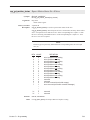
Commands ........................................................................................... 5-2
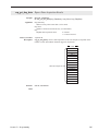
5.3.1 Command Summary ............................................................... 5-2
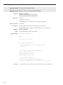
5.3.2 Command List ......................................................................... 5-6
Initialization␣ ............................................................................ 5-7
Configuration␣ ........................................................................ 5-11
Motion␣ ................................................................................... 5-31
Trajectory .............................................................................. 5-43
Motion-Related ...................................................................... 5-57
Servo ....................................................................................... 5-77
Data Acquisition .................................................................... 5-85
Digital I/O ............................................................................... 5-99
System .................................................................................. 5-105
User Programming ......................................................................... 5-109
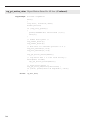
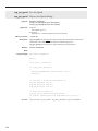
5.4.1 Visual C ................................................................................. 5-109
5.4.1.1 Overview ................................................................ 5-109
5.4.1.2 Examples ................................................................ 5-109
5.4.2 Visual Basic .......................................................................... 5-109
5.4.2.1 Overview ................................................................ 5-109
5.4.2.2 Examples ................................................................ 5-109
5.4.3 LabVIEW ............................................................................... 5-109
5.4.3.1 Overview ................................................................ 5-109
5.4.3.2 Example(s) ............................................................. 5-110
5.4.4 Error Handling ..................................................................... 5-111
v
Section 6 — Motion Control Tutorial␣ .............................................. 6-1
6.1
6.2
6.3
6.4
6.5
6.6
6.7
Motion Systems .................................................................................. 6-1
Specification Definitions .................................................................... 6-2
6.2.1 Following Error ........................................................................ 6-2
6.2.2 Error .......................................................................................... 6-3
6.2.3 Accuracy .................................................................................. 6-3
6.2.4 Local Accuracy ........................................................................ 6-4
6.2.5 Resolution ................................................................................ 6-4
6.2.6 Minimum␣ Incremental Motion ............................................... 6-5
6.2.7 Repeatability ............................................................................ 6-6
6.2.8 Backlash (Hysteresis) ............................................................ 6-6
6.2.9 Pitch, Roll, and Yaw ................................................................ 6-7
6.2.10 Wobble ..................................................................................... 6-8
6.2.11 Load Capacity .......................................................................... 6-9
6.2.12 Maximum Velocity .................................................................. 6-9
6.2.13 Minimum Velocity ................................................................... 6-9
6.2.14 Velocity Regulation ............................................................... 6-10
6.2.15 Maximum Acceleration ........................................................ 6-10
6.2.16 Combined Parameters .......................................................... 6-11
Control Loops ................................................................................... 6-11
6.3.1 PID Servo Loops .................................................................... 6-12
6.3.2 Feed-Forward Loops ............................................................. 6-14
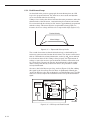
Motion Profiles .................................................................................. 6-15
6.4.1 Move ....................................................................................... 6-15
6.4.2 Jog ........................................................................................... 6-16
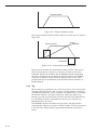
6.4.3 Home Search .......................................................................... 6-17
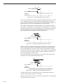
Encoders ............................................................................................ 6-19
Motors ................................................................................................ 6-22
6.6.1 Stepper Motors ...................................................................... 6-22
6.6.2 DC Motors .............................................................................. 6-27
Drivers ................................................................................................ 6-28
6.7.1 Stepper Motor Drivers ......................................................... 6-28
6.7.2 DC Motor Drivers .................................................................. 6-30
Section 7 — Servo Tuning␣ ..................................................................... 7-1
7.1
7.2
Tuning Principles ............................................................................... 7-1
Tuning Procedures ............................................................................. 7-1
7.2.1 Hardware And Software Requirements ............................... 7-2
7.2.2 Correcting Axis Oscillation .................................................... 7-2
7.2.3 Correcting Following Error .................................................... 7-2
7.2.4 Points To Remember .............................................................. 7-4
Section 8 — Optional Equipment␣ ...................................................... 8-1
8.1
8.2
vi
ESP6000 Controller Card ................................................................... 8-1
8.1.1 Terminal Block Board ............................................................ 8-1
8.1.2 Analog I/O Cable ...................................................................... 8-3
8.1.3 Digital I/O Cable ...................................................................... 8-4
8.1.4 Auxiliary I/O Cable .................................................................. 8-5
8.1.5 Driver Interface (100-100 pin) Cable .................................... 8-6
8.1.6 Motor/Driver (100-68 pin) Cable ........................................... 8-6
UniDrive6000 ....................................................................................... 8-7
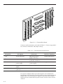
8.2.1 Motor Driver Card ................................................................... 8-7
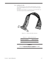
8.2.2 Rack-Mount Ears ..................................................................... 8-9
Section 9 — Advanced Capabilities␣ ................................................. 9-1
9.1
9.2
9.3
Motion Control Software Overview ................................................. 9-1
9.1.1 Introduction ............................................................................. 9-1
9.1.2 Control API ............................................................................... 9-1
9.1.2.1 System Initialization .................................................. 9-1
9.1.2.2 Configuration ............................................................. 9-1
9.1.2.3 Axis Control ................................................................ 9-2
9.1.3 Trajectory Control Process ................................................... 9-2
Data Acquisition Overview ............................................................... 9-2
PCI Bus Overview ............................................................................... 9-4
Appendix A — Error Messages␣ ........................................................... A-1
Appendix B — Trouble-Shooting and Maintenance␣ ................ B-1
B.1
B.2
B.3
Trouble-Shooting Guide ..................................................................... B-1
Fuse Replacement .............................................................................. B-3
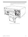
B.2.1 Replacing Fuses On The UniDrive Rear
Power Line Panel ..................................................................... B-3
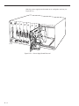
B.2.2 Replacing Fuses On The UniDrive Motor
Power Supply Board ............................................................... B-4
Cleaning ............................................................................................... B-7
Appendix C — Connector Pin Assignments␣ ................................ C-1
C.1
C.2
C.3
Table of Contents
ESP6000 Controller Card ................................................................... C-1
C.1.1 Main I/O (100-Pin) Connector ............................................... C-2
C.1.2 Motor/Driver Interface (100-to-68 Pin) Cable ..................... C-6
C.1.3 Digital I/O (50-Pin) JP4 Connector ........................................ C-9
C.1.4 Auxiliary I/O (40-Pin) JP5 Connector ................................. C-11
C.1.5 Analog I/O (26-Pin) JP2 Connector ..................................... C-15
UniDrive6000 Universal Motor Driver ........................................... C-17
C.2.1 Controller Input Connector ................................................. C-17
C.2.2 Motor Driver Card 25-Pin I/O Connector ........................... C-17
Terminal Block Board ...................................................................... C-21
C.3.1 MD4 15-Pin Connector .......................................................... C-22
C.3.2 Eighteen-Lead Connector..................................................... C-24
C.3.3 Optional Power Supply Connector ..................................... C-26
C.3.4 Nine-Lead Connector ............................................................ C-27
C.3.5 Jumpers .................................................................................. C-28
vii
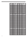
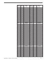
Appendix D — Binary Conversion Table␣ ...................................... D-1
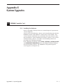
Appendix E — System Upgrades␣ ....................................................... E-1
E.1
ESP6000 Controller Card ................................................................... E-1
E.1.1 Installing New Software .......................................................... E-1
E.1.2 Installing New Firmware ........................................................ E-4
Appendix F — ESP Configuration Logic␣ ........................................ F-1
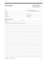
Appendix G — Factory Service␣ .......................................................... G-1
Service Form ...................................................................................................... G-3
viii
List of Figures
Figure 1.4-1 — ESP6000 Controller Card ...........................................................................................................................1-6
Figure 1.4-2 — ESP Configuration ......................................................................................................................................1-7
Figure 2.3-1 — ESP6000 Controller Card ...........................................................................................................................2-2
Figure 2.3-2 — UniDrive6000 Front and Rear View .......................................................................................................... 2-4
Figure 2.4-1 — Enclosure Removal ....................................................................................................................................2-6
Figure 2.4-2 — ESP6000 Controller Card Insertion Orientation ....................................................................................... 2-7
Figure 2.4-3 — Controller Card Device Driver Prompt (Representative Screen Only) ................................................. 2-7
Figure 2.4-4 — Install From Disk Message (Representative Screen Only)...................................................................... 2-8
Figure 2.4-5 — System Settings Change Message (Representative Screen Only) ........................................................... 2-8
Figure 2.4-6 — Windows 95 Start-Up Screen .....................................................................................................................2-9
Figure 2.4-7 — Control Panel Menu ...................................................................................................................................2-9
Figure 2.4-8 — Add/Remove Programs Properties Menu ............................................................................................... 2-10
Figure 2.4-9 — Install Program From Floppy Disk Or CD-ROM Screen ......................................................................... 2-11
Figure 2.4-10 — Run Installation Program ....................................................................................................................... 2-11
Figure 2.4-11 — ESP Welcome Screen ............................................................................................................................. 2-12
Figure 2.4-12 — ESP Select Destination Directory Screen .............................................................................................. 2-12
Figure 2.4-13 — ESP Ready To Install Screen .................................................................................................................. 2-13
Figure 2.4-14 — Installing Message Screen ...................................................................................................................... 2-14
Figure 2.4-15 — Insert New Disk Message Screen .......................................................................................................... 2-14
Figure 2.4-16 — ESP Installation Completed Screen ....................................................................................................... 2-15
Figure 2.4-17 — ESP Initialization Screen ....................................................................................................................... 2-15
Figure 2.4-18 — ESP6000 Error Message Screen ............................................................................................................. 2-16
Figure 2.4-19 — Line Voltage Select Switch .....................................................................................................................2-17
Figure 2.4-20 — Stage To UniDrive Connection .............................................................................................................. 2-18
Figure 2.4-21 — UniDrive To Controller Card Connection ............................................................................................. 2-19
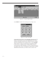
Figure 3.2-1 — Motion Drop-Down Menu ..........................................................................................................................3-2
Figure 3.2-2 — Motor Power Menu ..................................................................................................................................... 3-2
Figure 3.3-1 — Home Stages Menu..................................................................................................................................... 3-3
Figure 3.4-1 — Jog Menu .....................................................................................................................................................3-4
Figure 3.4-2 — Speed Menu ................................................................................................................................................3-5
Figure 3.4-3 — Set X(Y) Speed Menu .................................................................................................................................3-5
Figure 4.1-1 — Main Menu ..................................................................................................................................................4-2
Figure 4.1-2 — File Menu ....................................................................................................................................................4-3
Figure 4.1-3 — Setup Menu .................................................................................................................................................4-4
Figure 4.1-4 — Setup Resolution Sub-Menu .......................................................................................................................4-5
Figure 4.1-5 — Motion Setup PID Tab ................................................................................................................................4-6
Figure 4.1-6 — Motion Setup Trajectory Tab .....................................................................................................................4-6
Figure 4.1-7 — Setup Faults Sub-Menu ............................................................................................................................... 4-7
Figure 4.1-8 — Setup Hardware Amplifier I/O Tab ........................................................................................................... 4-8
Figure 4.1-9 — Setup Hardware Analog I/O Tab .............................................................................................................. 4-9
Figure 4.1-10 — Setup Hardware Digital I/O Tab ............................................................................................................. 4-9
Figure 4.1-11 — Setup Hardware Servo DAC Offset Tab ................................................................................................ 4-10
Figure 4.1-12 — Setup Hardware Travel Limit Tab ......................................................................................................... 4-10
Figure 4.1-13 — Setup UniDrive Sub-Menu ...................................................................................................................... 4-11
Figure 4.1-14 — Motion Menu ........................................................................................................................................... 4-12
Figure 4.1-15 — Stop Button .............................................................................................................................................4-12
Figure 4.1-16 — Cycle Motors Sub-Menu .......................................................................................................................... 4-13
Figure 4.1-17 — Status Menu ............................................................................................................................................4-13
Table of Contents
ix
Figure 4.1-18 — Position Status Menu ..............................................................................................................................4-14
Figure 4.1-19 — Help Menu ..............................................................................................................................................4-14
Figure 4.1-20 — About Screen ..........................................................................................................................................4-15
Figure 4.2-1 — Servo Tuning Main Screen ...................................................................................................................... 4-16
Figure 5.4-1 — VI Front Panel .........................................................................................................................................5-105
Figure 6.1-1 —Typical Motion Control System ..................................................................................................................6-1
Figure 6.2-1 — Position Error Test .....................................................................................................................................6-3
Figure 6.2-2 — High Accuracy for Small Motions .............................................................................................................. 6-4
Figure 6.2-3 — Low Accuracy for Small Motions ...............................................................................................................6-4
Figure 6.2-4 — Effect of Stiction and Elasticity on Small Motions ................................................................................... 6-5
Figure 6.2-5 — Error Plot ....................................................................................................................................................6-5
Figure 6.2-6 — Error vs. Motion Step Size ......................................................................................................................... 6-6
Figure 6.2-7 — Hysteresis Plot ............................................................................................................................................6-7
Figure 6.2-8 — Real vs. Ideal Position ...............................................................................................................................6-7
Figure 6.2-9 — Pitch, Yaw, and Roll Motion Axes ............................................................................................................. 6-8
Figure 6.2-10 — Pitch, Yaw and Roll ..................................................................................................................................6-8
Figure 6.2-11 — Wobble ......................................................................................................................................................6-8
Figure 6.2-12 — Position, Velocity, and Average Velocity ................................................................................................6-9
Figure 6.3-1 — Servo Loop ................................................................................................................................................6-11
Figure 6.3-2 — P Loop .......................................................................................................................................................6-12
Figure 6.3-3 — PI Loop ......................................................................................................................................................6-13
Figure 6.3-4— PID Loop ....................................................................................................................................................6-13
Figure 6.3-5 — Trapezoidal Velocity Profile .................................................................................................................... 6-14
Figure 6.3-6 — PID Loop with Feed-Forward ................................................................................................................... 6-14
Figure 6.3-7 — Tachometer-Driven PIDF Loop ................................................................................................................ 6-15
Figure 6.4-1— Trapezoidal Motion Profile ...................................................................................................................... 6-16
Figure 6.4-2 — Position and Acceleration Profiles .......................................................................................................... 6-16
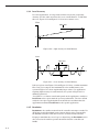
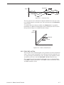
Figure 6.4-3 — Origin Switch and Encoder Index Pulse ................................................................................................. 6-17
Figure 6.4-4 — Slow-Speed Origin Switch Search ........................................................................................................... 6-18
Figure 6.4-5 — High/Low-Speed Origin Switch Search ................................................................................................... 6-18
Figure 6.4-6 — Origin Search From Opposite Direction ................................................................................................. 6-18
Figure 6.5-1 — Encoder Quadrature Output .................................................................................................................... 6-19
Figure 6.5-2 — Optical Encoder Scale ..............................................................................................................................6-20
Figure 6.5-3 — Optical Encoder Read Head .................................................................................................................... 6-20
Figure 6.5-4 — Single-Channel Optical Encoder Scale and Read Head Assembly ....................................................... 6-20
Figure 6.5-5 — Two-Channel Optical Encoder Scale and Read Head Assembly .......................................................... 6-21
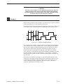
Figure 6.6-1 — Stepper Motor Operation ......................................................................................................................... 6-22
Figure 6.6-2 — Four-Phase Stepper Motor ....................................................................................................................... 6-22
Figure 6.6-3 — Phase Timing Diagram ............................................................................................................................ 6-23
Figure 6.6-4 — Energizing Two Phases Simultaneously ................................................................................................. 6-23
Figure 6.6-5 — Timing Diagram, Half-Stepping Motor .................................................................................................... 6-24
Figure 6.6-6 — Energizing Two Phases with Different Intensities ................................................................................. 6-24
Figure 6.6-7 — Timing Diagram, Continuous Motion (Ideal) ........................................................................................ 6-24
Figure 6.6-8 — Timing Diagram, Mini-Stepping .............................................................................................................. 6-24
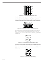
Figure 6.6-9 — Single Phase Energization ....................................................................................................................... 6-25
Figure 6.6-10 — External Force Applied .......................................................................................................................... 6-25
Figure 6.6-11 — Unstable Point ........................................................................................................................................6-25
Figure 6.6-12 — Torque and Tooth Alignment................................................................................................................. 6-26
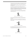
Figure 6.6-13 — DC Motor .................................................................................................................................................6-27
Figure 6.7-1 — Simple Stepper Motor Driver ................................................................................................................... 6-29
Figure 6.7-2 — Current Build-up in Phase ........................................................................................................................6-29
Figure 6.7-3 — Effect of a Short ON Time on Current ..................................................................................................... 6-29
Figure 6.7-4 — Motor Pulse with High Voltage Chopper ................................................................................................. 6-30
Figure 6.7-5 — DC Motor Voltage Amplifier .................................................................................................................... 6-30
Figure 6.7-6 — DC Motor Current Driver ......................................................................................................................... 6-31
Figure 6.7-7 — DC Motor Velocity Feedback Driver ........................................................................................................ 6-31
Figure 6.7-8 — DC Motor Tachometer Gain and Compensation .................................................................................... 6-32
x
Figure 8.1-1 — Terminal Block Board ............................................................................................................................... 8-2
Figure 8.1-2 — Analog I/O Cable .......................................................................................................................................8-3
Figure 8.1-3 — Digital I/O Cable ........................................................................................................................................ 8-4
Figure 8.1-4 — Auxiliary I/O Cable Connections .............................................................................................................. 8-5
Figure 8.1-5 — Driver Interface (100-100 pin) Cable ........................................................................................................ 8-6
Figure 8.1-6 — Motor/Driver (100-68 pin) Cable .............................................................................................................. 8-6
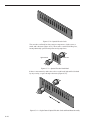
Figure 8.2-1 — Driver Card .................................................................................................................................................8-7
Figure 8.2-2 — Driver Card Installation .............................................................................................................................8-8
Figure 8.2-3— Rack-Mount Ear Installation .......................................................................................................................8-9
Figure 9.2-1 — Analog-To-Digital Flow Diagram ...............................................................................................................9-2
Figure B.2-1 — Rear Power Line Panel Fuse Replacement ............................................................................................. B-3
Figure B.2-2 — Rear Power Line Board Removal ............................................................................................................ B-5
Figure B.2-3 — Power Supply Board Removal ................................................................................................................. B-6
Figure B.2-4 — Power Supply Board Fuse Replacement ................................................................................................. B-7
Figure C.1-1 — Main I/O (100-Pin) Connector Orientation ............................................................................................. C-1
Figure C.1-2 — One-Hundred to Sixty-Eight Pin Cable Connector Orientation............................................................... C-2
Figure C.1-3 — JP2/JP4/JP5 Connector Orientation ........................................................................................................ C-2
Figure C.2-1 — UniDrive Controller Input Connector Orientation ................................................................................ C-17
Figure C.2-2 — Driver Card Connector Orientation ....................................................................................................... C-17
Figure C.3-1 — Terminal Block Board Connector Orientation ...................................................................................... C-21
Figure E.1-1 — Add/Remove Programs Properties Screen ............................................................................................. E-2
Figure E.1-2 — Select Uninstall Method Screen ............................................................................................................... E-3
Figure E.1-3 -— Perform Uninstall Screen ......................................................................................................................... E-3
Figure E.1-4 — ESP6000 Setup Menu ............................................................................................................................... E-4
Figure E.1-5 — Update Firmware Message Screen .......................................................................................................... E-4
Figure E.1-6 — Open Screen .............................................................................................................................................. E-5
Figure E.1-7 — Firmware Update Screen .......................................................................................................................... E-5
Figure E.1-8 — ESP6000 Initialization Screen .................................................................................................................. E-6
Figure F-1 — Configuration Logic .......................................................................................................................................F-1
Table of Contents
xi
List of Tables
Table 2.3-1 — ESP6000 Controls And Indicators ...............................................................................................................2-3
Table 2.3-2 — UniDrive6000 Controls And Indicators ......................................................................................................2-4
Table 4.1-1 — Stage (Motor) Type Settings .......................................................................................................................4-2
Table 4.1-2 — Stage (Motor) Trajectory Settings .............................................................................................................. 4-2
Table 5.2-1 — Software Version Requirements ................................................................................................................. 5-1
Table 5.2-2 — API Function Categories ..............................................................................................................................5-2
Table 5.3-1 — Commands ...................................................................................................................................................5-2
Table 7.2-1 — Servo Parameter Functions ........................................................................................................................7-5
Table 8-1 — Optional Equipment .......................................................................................................................................8-1
Table 8.1-1 — Terminal Block Board Functions ...............................................................................................................8-2
Table 8.1-2 — Analog I/O Cable Connections................................................................................................................... 8-3
Table 8.1-3 — Digital I/O Cable Connections ................................................................................................................... 8-4
Table 8.1-4 — Auxiliary I/O Connections ......................................................................................................................... 8-5
Table 9.2-1 — Acquisition Array ........................................................................................................................................9-3
Table 9.2-2 — Data Acquisition Commands ...................................................................................................................... 9-4
Table 9.3-1 — PCI Design Goals .........................................................................................................................................9-5
Table A-1 — Error Messages ............................................................................................................................................. A-2
Table B.1-1 — Trouble-Shooting Guide ............................................................................................................................. B-2
Table C.1-1 — Main I/O Connector Pin-Outs .................................................................................................................... C-3
Table C.1-2. — Motor/Driver Interface (100-to-68 pin) Cable Connector Pin-Outs ....................................................... C-7
Table C.1-3 — Digital Connector Pin-Outs ...................................................................................................................... C-10
Table C.1-4 — Auxiliary Connector Pin-Outs .................................................................................................................. C-12
Table C.1-5 — Analog Connector Pin-Outs ..................................................................................................................... C-15
Table C.2-1 — Driver Card Connector Pin-Outs .............................................................................................................. C-18
Table C.3-1 — MD4 Connector Pin-Outs ......................................................................................................................... C-22
Table C.3-2 — Eighteen-Lead Upper Connector Pin-Outs .............................................................................................. C-24
Table C.3-3 — Eighteen-Lead Lower Connector Pin-Outs .............................................................................................. C-25
Table C.3-4 — Optional Power Supply Connector Pin-Outs .......................................................................................... C-26
Table C.3-5 — Nine-Pin Connector Pin-Outs ................................................................................................................... C-27
Table C.3-6 — Jumpers .................................................................................................................................................... C-28
Table G-1 — Technical Customer Support Contacts ........................................................................................................ G-1
xii
Section 1
Introduction
1.1
Scope
This manual provides descriptions and operating procedures for the
Enhanced System Performance (ESP) motion system, consisting of the
ESP6000 controller card, UniDrive6000 universal motor driver, and
various stages.
Safety considerations, conventions and definitions, and a system overview
are provided in Section 1, Introduction.
Procedures for unpacking the equipment, hardware and software requirements, descriptions of controls and indicators, and setup procedures are
provided in Section 2, System Setup.
Instructions for configuring and powering up the UniDrive and stage motors,
for home and jog motions, and for system shut-down are provided in
Section 3, Quick Start.
Features and operation of the Windows motion and tuning utilities are
described in Section 4.
Newport-provided commands, language-specific information, and errorhandling procedures are provided in Section 5, Programming.
An overview of motion parameters and equipment is provided in Section 6,
Motion Control Tutorial.
Servo tuning principles and procedures are given in Section 7.
Procedures for ordering, installing, and using optional equipment are
provided in Section 8.
The motion control software, data acquisition, and Peripheral Component
Interconnect (PCI) bus structure, are described in Section 9, Advanced
Capabilities.
The following information is provided in the Appendices:
Section 1 — Introduction
–
Error messages
–
Trouble-shooting and maintenance
–
Connector pin assignments
–
Decimal/ASCII/binary conversion table
–
System upgrades for software and firmware
–
ESP configuration logic
–
Factory service
1-1
1.2
Safety Considerations
The following general safety precautions must be observed during all phases
of operation of this equipment. Failure to comply with these precautions
or with specific warnings elsewhere in this manual violates safety standards
of design, manufacture, and intended use of the equipment.
Disconnect or do not plug in the power cord in the following circumstances:
–
If the power cord or any other attached cables are frayed or damaged.
–
If the power plug or receptacle is damaged.
–
If the unit is exposed to rain or excessive moisture, or liquids are
spilled on it.
–
If the unit has been dropped or the case is damaged.
–
If you suspect service or repair is required.
–
When you clean the case.
To protect the equipment from damage and avoid hazardous situations,
follow these recommendations:
–
Do not open the UniDrive6000 except to replace the rear power line
panel fuses and power supply board fuse (see Appendix B, Trouble
Shooting). There are no user-serviceable parts inside the UniDrive.
–
Do not make modifications or parts substitutions.
–
Return equipment to Newport Corporation for service and repair.
–
Do not touch, directly or with other objects, live circuits inside the unit.
–
Do not operate the unit in an explosive atmosphere.
–
Keep air vents free of dirt and dust.
–
Do not block air vents.
–
Keep liquids away from unit.
–
Do not expose equipment to excessive moisture (>90% humidity).
WARNING
All attachment plug receptacles in the vicinity of this unit are to be of
the grounding type and properly polarized. Contact an electrician to
check faulty or questionable receptacles.
WARNING
This product is equipped with a 3-wire grounding type plug. Any
interruption of the grounding connection can create an electric shock
hazard. If you are unable to insert the plug into your wall plug
receptacle, contact an electrician to perform the necessary alterations to
assure that the green (green-yellow) wire is attached to earth ground.
1-2
WARNING
This product operates with voltages that can be lethal. Pushing objects
of any kind into cabinet slots or holes, or spilling any liquid on the
product, may touch hazardous voltage points or short out parts.
WARNING
Opening or removing covers will expose you to hazardous voltages.
observe the following precautions:
• Turn power OFF and unplug the unit from its power source;
• Disconnect all cables;
• Remove jewelry from hands and wrists;
• Use insulated hand tools only;
• Maintain grounding by wearing a wrist strap attached to instrument chassis.
1.3
Conventions And Definitions
This section provides a list of symbols and their definitions, and commonly-used terms found in this manual.
1.3.1 Definitions and Symbols
The following are definitions of safety and general symbols used on
equipment or in this manual.
Warning. Calls attention to a procedure, practice or condition which, if
not correctly performed or adhered to, could result in injury or death.
WARNING
Caution. Calls attention to a procedure, practice, or condition which, if not
correctly performed or adhered to, could result in damage to equipment.
CAUTION
Note. Calls attention to a procedure, practice, or condition which is
considered important to remember in the context.
NOTE
Section 1 — Introduction
1-3
This symbol indicates the principal on/off switch is in the on position.
This symbol indicates the principal on/off switch is in the off position.
A terminal which is used to connect instrument to earth ground.
This symbol informs operator to read instructions in the operator manual
before proceeding.
1-4
1.3.2 Terminology
The following is a brief description of the terms specific to motion control
and the ESP6000 controller card and UniDrive6000 universal motor driver
equipment.
API— Application Programmer Interface
Axis — a logical name for a stage/positioner/motion device
DLL — Dynamic Link Library
Encoder — a displacement measuring device, term usually used for both
linear and rotary models
ESP — Enhanced System Performance motion system comprised of
ESP6000 controller card, UniDrive universal motor driver, and compatible
stage(s). ESP is synonymous with a plug-and-play motion system.
ESP6000 — the ESP6000 controller card
ESP-compatible — refers to Newport Corporation stage with its own
firmware-based configuration parameters. Newport stages or other stages
without this feature are referred to as being not ESP-compatible and must
be uniquely configured by the user.
Home (position) — the unique point in space that can be accurately found
by an axis, also called origin
Home search — a specific motion routine used to determine the home
position
Jog — a motion of undetermined-length, initiated manually
Motion device — electro-mechanical equipment. Used interchangeably
with stage and positioner
Move — a motion to a destination, initiated manually
Origin — used interchangeably with home
PCI — Peripheral Component Interconnect (type of personal computer bus)
PID — a closed loop algorithm using proportional, integral, and derivative
gain factors.
Positioner — used interchangeably with stage and motion device
Stage — used interchangeably with motion device and positioner
UniDrive6000 — the universal motor driver used with the ESP6000 controller card
Section 1 — Introduction
1-5
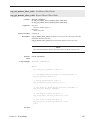
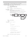
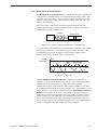
1.4
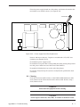
System Overview
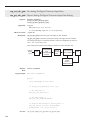
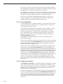
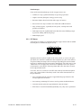
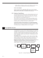
The Enhanced System Performance (ESP) architecture consists of the
ESP6000 controller card, UniDrive6000 universal motor driver, and ESPcompatible stages. The ESP6000 controller card (see Figure 1.4-1) is
designed for convenient installation in the user’s own PC.
The ESP 6000’s Windows-based setup utility provides a full range of
functions for configuring and operating from one to six axes.
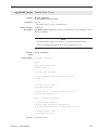
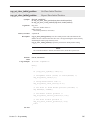
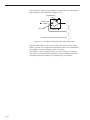
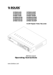
The system is designed to operate with Newport Corporation’s ESPcompatible stages, but can be configured to function with other stages. A
typical PC-based ESP 6000 system configuration with the UniDrive6000 and
one stage is shown in Figure 1.4-2.
N97005A
Figure 1.4-1 — ESP6000 Controller Card
1-6
r Driver
Universal Moto
UniDrive6000
AXIS 4
AXIS 5
AXIS 6
AXIS 3
AXIS 2
STOP ALL
P0WE R
AXIS 1
STATUS
ER
NO DRIV
ON
MOTOR
R OFF
MOTO
FAULT
STATUS
P0WE R ON
P0WE R FAULT
—
N97111C
Figure 1.4-2 — ESP Configuration
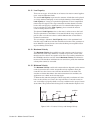
1.4.1 Features
Many advanced features make the ESP 6000 the preferred system for
precision motion applications:
Section 1 — Introduction
–
Combined data acquisition and motion control
–
‘Plug-and-play’ controller, driver, and stage setup
–
Bench-top or rack-mount configuration for the UniDrive6000
–
Configured for any combination of motor type (DC/stepper) or size
–
Feed-forward servo algorithm for smooth and precise motion
–
Multi-axis synchronization
–
Powerful motion programming capabilities in Visual Basic/C, and
LabVIEW languages. Extensive set of Newport Corporation-provided
commands.
–
User-selectable displacement units
1-7
1.4.2 Specifications
1.4.2.1 ESP6000 Controller Card
Trajectory Type:
–
Non-synchronized motion
–
Multi-axis synchronized motion
–
S-curve velocity profile
–
Trapezoidal velocity profile
DC Motor Control:
–
16-bit servo DAC resolution
–
16 MHz maximum encoder input frequency
–
PID with velocity and acceleration feed-forward servo loop
–
0.4 ms digital servo cycle
Stepper Motor Control:
–
2.5 MHz maximum pulse rate
–
Open or closed-loop operation
–
PID with velocity feed-forward closed-loop mode
Computer Interfaces:
–
PCI bus interface
Utility Interfaces (Connectors):
–
Analog I/O: 16-bit, 8 channel muxed analog inputs
–
Digital I/O: 24-bit, Opto22-compatible digital I/O
–
Auxiliary I/O: 2 channel auxiliary encoder counters
Programming:
–
Visual BASIC
–
Visual C/C++
–
LabVIEW
Memory:
–
512KB firmware flash EPROM
–
128KB system configuration flash EPROM
Power:
+ 5 Volts, 1.8 Amps (maximum)
+ 12 Volts, 0.2 Amps (maximum)
–12 Volts, 0.2 Amps (maximum)
1-8
Physical:
–
Width: 0.75”
–
Height: 4.0” including face plate
–
Depth: 14.0” including bracket
–
Weight: 0.6 lb.
1.4.2.2 UniDrive6000 Universal Motor Driver
Number Of Motion Axes:
–
1 to 6, in any combination or order of DC and stepper motors
Stage Compatibility:
–
ESP-compatible (Smart-Stage) devices, non-ESP compatible Newport
stages, other stages
DC Motor Control:
–
4 Amps, 60 Volts
Stepper Motor Control:
–
4 Amps, 60 Volts
–
10x micro-stepping resolution factor
–
Full, half, and mini-step capability
Power:
–
Input voltage: 110/220V ±10%
–
Frequency: 50/60Hz
–
Current: 4 Amps (maximum input current)
Physical:
–
Height: 7.00” including feet
–
Width: 17.0”
–
Depth: 17.0”
–
Weight: 19.0 lb. (with 6 driver cards)
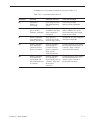
Fuses:
Location
Type
Rear Power Line Panel
4A, 250V (SLO-BLO)
Power Supply Board
3.15 A, 250V
1.4.2.3 Environmental Limits
Section 1 — Introduction
–
Operating Temperature: 0° Centigrade to 40° Centigrade
–
Operating Humidity: 90% non-condensing
–
Storage Temperature: -20° Centigrade to 60° Centigrade
1-9
1-10
Section 2
System Setup
This Section defines the hardware and software requirements for operation,
the equipment controls and indicators, and the step-by-step procedures
needed to prepare the system for use.
2.1
Unpacking
Before unpacking any components, inspect the shipping container(s) for
evidence of damage. Notify the shipping carrier of damage.
CAUTION
All equipment is packaged in electrostatic material. Unpack carefully
to avoid damage to equipment and packing materials.
Remove the packing list from the shipping container(s). Verify that the
items listed on the packing slip are in the container(s). Refer to Appendix G,
Factory Service, for reporting discrepancies.
CAUTION
The ESP6000 controller card and stages are sensitive to static
electricity. Wear a properly grounded anti-static strap when
handling equipment.
Further inspection of equipment should be made with the following
precautions:
–
Do not remove the ESP6000 controller card from the anti-static shipping bag until you are ready to begin installation.
–
Avoid touching components on the ESP6000 controller card.
–
Hold the ESP6000 controller card by its edges or mounting brackets.
All equipment is tested and inspected prior to shipment. Inspect the
equipment, and refer to Appendix G, Factory Service, for reporting
discrepancies.
Section 2 — System Set-Up
2-1
2.2
PC Hardware and Software Requirements
PC hardware and software requirements include:
1. Personal computer with a 486DX or higher processor
2. PCI-compatible (full-length) card slot for ESP6000 board
3. Microsoft Windows 95 operating system or Microsoft Windows NT
Workstation operating system 4.0 or later
4. 4 MB of memory for Windows 95 (8 MB recommended)
5. 12 MB of memory for Windows NT Workstation
6. 20 MB of hard disk space
7. VGA or higher-resolution video adapter
8. Microsoft Mouse or compatible pointing device
9. One interrupt line
10. 3 1/2″ floppy disk drive (for installation only)
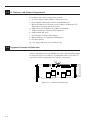
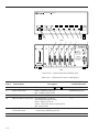
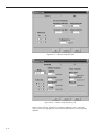
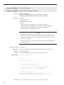
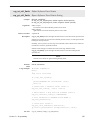
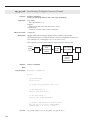
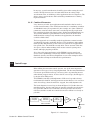
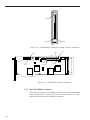
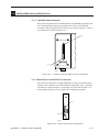
2.3
Equipment Controls and Indicators
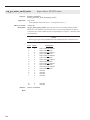
Controls and indicators for the ESP6000 controller card and UniDrive6000
are shown in Figures 2.3-1 and 2.3-2, and defined in Tables 2.3-1 and 2.3-2,
respectively. Refer to Appendix C for connector orientations.
4
3
2
1
N97121
Figure 2.3-1 — ESP6000 Controller Card
2-2
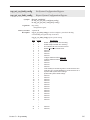
Table 2.3-1 — ESP6000 Controls And Indicators
Reference
Designation
Nomenclature
Description
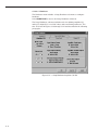
1
Reset
LED state controlled by ‘watchdog’ timer and PCI interface. LED OFF
indicates board is in reset state. Possible causes for reset state include:
1. Normal power-on reset
2. Application Programmer Interface (API) initialization command
3. +5V below operating range
4. Digital Signal Processor (DSP) not communicating with ‘watchdog’
timer.
2
Error
LED 2 will flash ON/OFF at approximately 0.5 second intervals as
long as there is an unread error message on-board.
3
Motion
LED 3 will remain illuminated (ON) while any axis is in motion.
4
Communication
LED 4 will illuminate continuously when API commands are received.
Section 2 — System Set-Up
2-3
Universal Motor Driver
POWER
STATUS
UniDrive6000
STOP ALL
AXIS 1
AXIS 2
AXIS 3
AXIS 4
AXIS 5
AXIS 6
STATUS
NO DRIVER
MOTOR ON
MOTOR OFF
FAULT
POWER ON
POWER FAULT
1 2
3
4
6
5
7
9
8
FRONT
15
14
13
12
11
10
AXIS
CONTROLLER
6
5
4
3
2
1
POWER
SUPPLY
CONTROLLER INPUT
!
CAUTION:
NO USER SERVICEABLE
PARTS INSIDE. REFER
SERVICING TO QUALIFIED
SERVICE PERSONNEL.
LINE
VOLTAGE
SELECT
90-120V OR
115V 200-240V
50/60 Hz
MAX 4 AMP
WARNING:
FOR CONTINUED PROTECTION
AGAINST FIRE RISK,
REPLACE ONLY WITH FUSE
OF SPECIFIED RATING.
FUSE
4A, SLO–BLO, 250V
GROUND
POST
MODEL No. UNIDRIVE6000
SERIAL No.
IRVINE, CA USA
XXXXXX
XXXX
N97100F
REAR
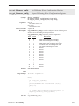
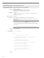
Figure 2.3-2 — UniDrive6000 Front and Rear View
Table 2.3-2 — UniDrive6000 Controls And Indicators
Item #
Nomenclature
Description
1
Power on/off switch
Turns system power ON
2
Power status LED
Green = UniDrive power on
Red = UniDrive power fault
Illuminated (green)
3
STOP ALL switch
Turns off motor power
Out (not depressed)
4-9
LED, axis driver card status
Not illuminated = No driver
(card not physically present)
Green = Motor power on
Yellow = Motor off, driver card installed
Red = Driver fault
——
10
LINE SELECT
VOLTAGE switch
Sets UniDrive to operate at 115 (range 90-120) ——
or 230 (range 200-240) input VAC
11-15
LED, axis driver card status
Same as item numbers 4-9
2-4
/OFF
Normal Operating
Condition/Position
In (depressed)
——
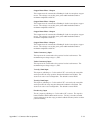
2.4
Installation and Connection
2.4.1
Installing the ESP6000 Controller Card and Software Driver
Power down the computer. Refer to the computer user manual for
procedures.
WARNING
This product operates with voltages that can be lethal. Pushing objects
of any kind into cabinet slots or holes, or spilling any liquid on the
product, may touch hazardous voltage points or short out parts.
WARNING
Opening or removing covers will expose you to hazardous voltages.
Observe the following precautions before proceeding:
• Turn power OFF and unplug the unit from its power source;
• Disconnect all cables;
• Remove jewelry from hands and wrists;
• Use insulated hand tools only;
• Maintain grounding by wearing a wrist strap attached to
instrument chassis.
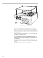
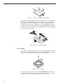
Remove the enclosure/housing from the computer. Removal of an enclosure from a representative PC is shown in Figure 2.4-1. Refer to computer
user documentation or contact the computer dealer factory service
department for disassembly/assembly procedures.
Section 2 — System Set-Up
2-5
N97115
Figure 2.4-1 — Enclosure Removal
Locate an open PCI card slot in the chassis which is not obscured by
adjacent cards. If other cards are protruding into the PCI slot space, it
may be necessary to re-locate them in order to install the ESP6000 card.
PCI spaces are identifiable by a double-row female edge connector on the
PC motherboard.
Remove the retaining screw(s) on the inside of the cut-out panel for the
PCI card slot, and remove the panel.
Due to varying card guide configurations of computers, it may be necessary to remove the bracket at the end of the ESP6000 card in order to
install the card. Make a visual determination before attempting to continue installation.
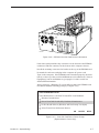
Insert the 100-pin connector edge of the ESP6000 card through the open
panel, and the rear of the card into the card guide at the back of the PCI
card slot.
Orientation for card insertion is shown in Figure 2.4-2.
2-6
N97114A
Figure 2.4-2 — ESP6000 Controller Card Insertion Orientation
Push down gently until the edge connector on the bottom of the ESP6000
card mates with the connector at the bottom of the computer chassis.
Install the retaining screw into the bracket at the top of the ESP6000 card.
Re-attach the enclosure and plug in the computer AC power cord.
Turn on the computer. If the ESP6000 card is installed properly, the front
LED (1) at the top of the card should illuminate red continuously. Refer to
Equipment Controls and Indicators, paragraph 2.3 of this section for
detailed LED information.
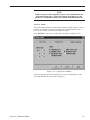
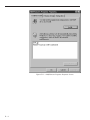
After booting-up, a Windows 95 system will respond to the ESP6000 card
installation with the following prompt (see Figure 2.4-3)
NEW HARDWARE FOUND
Select Which Driver You Want To Install For Your Hardware:
■ Windows Default Driver
■ Driver From Disk Provided By Hardware Manufacturer
■ Do Not Install A Driver (Windows will Not Prompt You Again)
■ Select From A List Of Alternate Drivers
OK
CANCEL
HELP
Figure 2.4-3 — Controller Card Device Driver Prompt
(Representative Screen Only)
Section 2 — System Set-Up
2-7
Select DRIVER FROM DISK PROVIDED BY HARDWARE MANUFACTURER
and press OK. Another Windows 95 prompt appears (see Figure 2.4-4).
INSTALL FROM DISK
Insert The Manufacturer’s Installation Disk Into The Drive Selected,
And Then Press OK
OK ■
CANCEL ■
BROWSE ■
Copy Manufacturer’s Files From:
[A:\
]
Figure 2.4-4 — Install From Disk Message (Representative Screen Only)
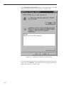
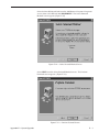
Insert the disk labeled ESP6000 Windows 95 Device Driver into the computer floppy disk drive and select OK. Another Windows 95 prompt
appears (see Figure 2.4-5).
SYSTEM SETTINGS CHANGE
To Finish Setting Up Your New Hardware, You Must Re-Start Your
Computer. Do You Want To Re-Start Your Computer Now?
YES ■
NO ■
Figure 2.4-5 — System Settings Change Message (Representative Screen Only)
Remove the device driver floppy disk.
Select YES to re-boot the system and actuate the driver.
2-8
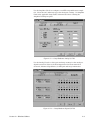
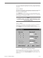
2.4.2 Installing Windows Software
The Windows Interface Software disk set (which includes software utilities, DLL, and language libraries) can be installed any time after the
ESP6000 controller card and driver software have been installed.
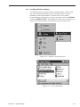
From the Windows 95 desk-top, press the start button and select SETTINGS
and then CONTROL PANEL. The Windows 95 start-up screen appears (see
Figure 2.4-6), followed by the Control Panel menu (see Figure 2.4-7).
Figure 2.4-6 — Windows 95 Start-Up Screen
Figure 2.4-7 — Control Panel Menu
Section 2 — System Set-Up
2-9
Select ADD/REMOVE PROGRAMS from the Control Panel menu. The Add/
Remove Programs Properties menu appears (see Figure 2.4-8).
Figure 2.4-8 — Add/Remove Programs Properties Menu
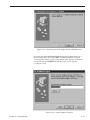
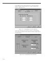
Select the Install/Uninstall tab from the Add/Remove Programs Properties
menu, then select INSTALL. The Install Program From Floppy Disk Or CDROM screen appears (see Figure 2.4-9).
2-10
Figure 2.4-9 — Install Program From Floppy Disk Or CD-ROM Screen
Insert the disk labeled ESP6000 Windows Interface Software Disk 1 of 4
into the floppy drive and select NEXT. The Run Installation Program
screen appears (Figure 2.4-10). Verify that the path appears as shown in
the screen and select FINISH. The ESP Welcome screen appears
(see Figure 2.4-11).
Figure 2.4-10 — Run Installation Program
Section 2 — System Set-Up
2-11
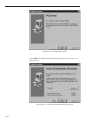
Figure 2.4-11 — ESP Welcome Screen
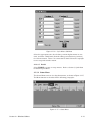
Select NEXT. The ESP Select Destination Directory screen appears (see
Figure 2.4-12).
Figure 2.4-12 — ESP Select Destination Directory Screen
2-12
Select NEXT. The ESP Ready To Install screen appears (see Figure 2.4-13).
Figure 2.4-13 — ESP Ready To Install Screen
Section 2 — System Set-Up
2-13
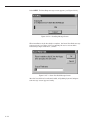
Select NEXT. The Installing message screen appears (see Figure 2.4-14).
Figure 2.4-14 — Installing Message Screen
When installation of the first disk is complete, the Insert New Disk message
screen appears (see Figure 2.4-15) prompting the user to insert disk 2.
Follow the prompts for disks 2, 3, and 4.
Figure 2.4-15 — Insert New Disk Message Screen
After the last disk has been down-loaded, an Updating System Configuration message screen appears briefly.
2-14
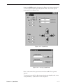
When installation is complete, the ESP installation Completed screen
appears (see Figure 2.4-16), and the interface software is then available for
use. Select FINISH to return to the Control panel menu.
Figure 2.4-16 — ESP Installation Completed Screen
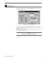
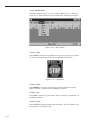
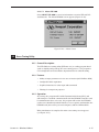
2.4.3 Verifying Communication Between the ESP6000 Card and the PC
The ESP 6000 software performs a verification each time the system is
booted-up. An ESP Initialization message screen appears that indicates
the ESP6000 controller card status, the UniDrive axes configured, and
ESP-compatible stages found during initialization (see Figure 2.4-17).
Figure 2.4-17 — ESP Initialization Screen
Section 2 — System Set-Up
2-15
If the ESP6000 controller card is not present or communicating then an
error message appears (see Figure 2.4-18).
Figure 2.4-18 — ESP6000 Error Message Screen
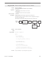
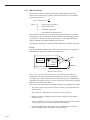
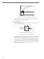
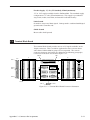
2.4.4 Selecting The UniDrive6000 Line Voltage
Unplug the UniDrive6000 AC power cord from the power source, and
disconnect it from any equipment.
Locate the line voltage selection switch at the right rear of the UniDrive
(see Figure 2.4-19).
Use a flat-bladed screwdriver to move the switch to the upper position
(115V), or to the lower position (230V), depending on the local line voltage.
Input voltage ranges and frequencies are shown adjacent to the switch.
2-16
AXIS
CONTROLLER
!
6
5
4
3
2
1
POWER
SUPPLY
LINE
VOLTAGE
SELECT
CAUTION:
NO USER SERVICEABLE
PARTS INSIDE. REFER
SERVICING TO QUALIFIED
SERVICE PERSONNEL.
90-120V OR
200-240V
115V 50/60 Hz
230V
MAX 4 AMP
WARNING:
FOR CONTINUED PROTECTION
AGAINST FIRE RISK,
REPLACE ONLY WITH FUSE
OF SPECIFIED RATING.
FUSE
4A, SLO–BLO, 250V
115V
GROUND
POST
N97101D
Figure 2.4-19 — Line Voltage Select Switch
CAUTION
Verify that the UniDrive6000 power switch at the front of the unit is
OFF before connecting the AC power cord.
CAUTION
Before applying AC power to the UniDrive6000, set the line voltage
selection switch to the local AC line voltage.
Section 2 — System Set-Up
2-17
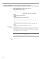
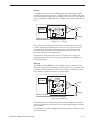
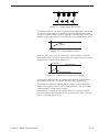
2.4.5 Connecting Stages
All ESP-compatible stages are electrically and physically compatible with
the UniDrive6000. ESP-compatible stages are recognizable by an ESP logo.
Stages which are not ESP-compatible do not have an ESP logo. If an ESPcompatible motion system was purchased, all necessary hardware to
connect the stage with the UniDrive6000 is included. The stage connects
to the UniDrive6000 via a shielded custom cable that carries all power and
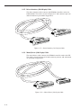
control signals (encoder, limits, and home signals). The cable is terminated with a standard 25-pin D-Sub connector.
CAUTION
Make sure the UniDrive6000 and ESP6000 are powered off.
CAUTION
Position stage(s) on a flat, stable surface before connection to
a rack-mounted UniDrive
Carefully connect one end of the cable to the stage and the other end to a
driver axis on the UniDrive6000 (see Figure 2.4-20). Secure both connectors
by tightening the thumbscrews. Refer to Appendix G, Factory Service to
order replacement cables (part number 52911).
CON TRO
LLER INPU
T
CON TRO
AXIS
LLER
6
5
4
! CAUT
ION:
NO USE
R SER
PARTS INS VICEABLE
IDE. REF
SERVIC
ER
ING TO
QUALIFI
SERVIC
ED
E PERSON
NEL.
WARN
MODEL
No. UNIDR
IVE6000
SERIAL
No.
IRVINE,
CA USA
ING:
FOR CON
TINUED
PROTEC
AGAINST
FIRE RISK TION
REP LAC
,
E ONLY
WITH
OF SPE
CIFIED RAT FUSE
ING.
FUSE
4A, SLO
-BLO, 250V
3
2
POW ER
1 SUP PLY
LINE
VOLTAG
E
SEL ECT
90-120V
OR
200-240V
50/60 HZ
MAX 4 AMP
GROUND
POS T
N97112B
Figure 2.4-20 — Stage To UniDrive Connection
2-18
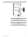
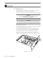
2.4.6 Connecting the UniDrive6000 to the ESP6000 Controller Card
WARNING
All attachment plug receptacles in the vicinity of this unit are to be of
the grounding type and properly polarized. Contact an electrician to
check faulty or questionable receptacles.
WARNING
This product is equipped with a 3-wire grounding type plug. Any
interruption of the grounding connection can create an electric shock
hazard. If you are unable to insert the plug into your wall plug receptacle, contact an electrician to perform the necessary alterations to
assure that the green (green-yellow) wire is attached to earth ground.
CAUTION
Verify proper alignment before inserting cables into connectors.
Do not force.
With the UniDrive6000 and personal computer powered off, attach the
supplied 100-pin cable to the connector labeled CONTROLLER INPUT at
the rear of the UniDrive6000. Next attach the cable to the ESP6000 card
connector at the rear of the personal computer (see Figure 2.4-21). Connector orientation is shown in Appendix C. Secure both connectors with
the locking thumbscrews.
CONT ROLLE
R INPUT
CONTROLLE
R
AXIS
6
!
5
4
3
CAUTIO
N:
NO USER
SERVICEAB
PARTS
LE
INSIDE.
REFER
SERVICING
TO QUAL
SERVICE
IFIED
PERSONNE
L.
2
POWER
1 SUPPLY
LINE
VOLTAGE
SELECT
90-120V
OR
200-240V
50/60 HZ
MAX 4 AMP
WARNI
NG:
MODEL No.
UNIDRIVE
6000
SERIAL No.
IRVINE, CA
USA
FOR CONT
INUED
PROTECTIO
AGAINST
N
FIRE RISK,
REPLACE
ONLY WITH
OF SPEC
FUSE
IFIED RATIN
G.
FUSE
4A, SLO-B
LO, 250V
GROUND
POST
N97113C
Figure 2.4-21 — UniDrive To Controller Card Connection
NOTE
To ensure proper ventilation for the UniDrive, maintain a distance of
at least 1” between a free-standing UniDrive and other equipment.
Section 2 — System Set-Up
2-19
2-20
Section 3
Quick Start
3.1
General Description
The following paragraphs cover procedures for operation after all equipment has been connected, and both the ESP6000 controller card driver and
setup utility have been installed (see the System Setup section). Information includes how to power up the UniDrive and stage motor(s), activate
home and jog motions, and to shut down the system. These procedures
enable a user to verify that stages are functioning properly and to provide a
limited overview of the Windows Motion Utility. Refer to the Windows
Utilities and Programming sections for detailed operating procedures. Refer
to the Setup UniDrive menu in the Windows Utilities section to configure the
UniDrive for non-compatible (non-SmartStage) equipment operation.
3.2
Motor On
CAUTION
Place stages on a flat surface and move objects which could restrict
their travel before turning on stage motors. Be prepared to turn
motors off quickly if you observe abnormal operation by pressing
the red STOP ALL button on the UniDrive.
With the PC powered on and software installed, turn on the UniDrive by
pressing the power switch at the front of the unit. The UniDrive is automatically configured for the appropriate motor at power-up. Select PROGRAMS,
ESP6000, and then ESP-UTIL to boot-up the ESP-util.exe program.
For ESP6000-compatible stages, select MOTION from the ESP 6000 Main
Menu. The Motion drop-down menu appears (see Figure 3.2-1).
Section 3 — Quick Start
3 - 1
Figure 3.2-1 — Motion Drop-Down Menu
Select ENABLE. The Motor Power menu appears (see Figure 3.2-2).
Figure 3.2-2 — Motor Power Menu
Select numbered axes buttons one-by-one to turn on the motors you have
connected to the specific axes, or select ALL ON to enable all motors.
Buttons for enabled and connected motors will illuminate green, and the
axis LED on the UniDrive will turn green to indicate a motor-on condition.
Click on an enabled button once to disable a motor, or select ALL OFF to
disable all motors. Buttons for disabled motors will illuminate yellow.
If a motor type is not defined (because no ESP-compatible stages are
detected) the button will not illuminate. If an axis is configured and motor
type defined, but the stage is not installed for a numbered axis, the button
will illuminate black. However, you will not be able to select the axis.
3 - 2
3.3
Homing a Stage
From the Motion drop-down menu, select HOME. The Home Stages screen
appears (see Figure 3.3-1)
Figure 3.3-1 — Home Stages Menu
Select an axis and search mode (Home Switch Only or Home Switch &
Index), enter the number of units in the Home Speed input box, and Select
START to home the stage(s).
Home each axis one by one. Verify that each stage carriage moves to its
home (typically center) position.
NOTE
Enable stage(s) motor power before homing.
Section 3 — Quick Start
3 - 3
3.4
Jog
From the Motion drop-down menu, select JOG (See Figure 3.2-1) or select
the JOG button from the tool bar. The Jog menu appears (see Figure 3.4-1).
Figure 3.4-1 — Jog Menu
NOTE
Enable stage(s) motor power before jogging.
3 - 4
Next select SPEED from the Jog menu (see Figure 3.4-2), then select the X
or Y axis option from the Speed drop-down menu. The Set X/Y Speed
menu appears (see Figure 3.4-3).
Figure 3.4-2 — Speed Menu
Figure 3.4-3 — Set X(Y) Speed Menu
Enter a value in the New Speed text box and select OK. The Jog menu
appears.
To execute a jog in the Free Run (unspecified motion length) mode, select
a stage number (1 - 6) in the X or Y-axis sub-panels.
Section 3 — Quick Start
3 - 5
NOTE
You cannot designate both the X and Y axes for the same stage axis number.
Press an X or Y arrow key to move a stage. Press and quickly release the
arrow key for one-count (single) motions. Press and hold down an arrow
key for continuous movement, and release the arrow key to stop movement.
To execute a jog in the Index (specified motion length) mode, first select
MODE from the Jog menu, then INDEX from the Mode drop-down menu.
Input values for the X or Y axis in the Index Distance sub-panel, and press
an arrow key to start a movement. Each depression of the arrow key will
produce a movement specified by the entry in the Index Distance sub-panel.
NOTE
Stage hardware travel limits are determined by the stage itself
and cannot be overridden.
3.5
System Shut-Down
To shut down the system entirely, perform the following:
Wait for the stage(s) to complete their movement and come to a halt.
Select ENABLE from the ESP-util Windows utility Motion menu and press
ALL OFF to disable power.
Depress and release the UniDrive6000 power switch at the front of the unit.
Power off the personal computer.
3 - 6
Section 4
Windows Utilities
4.1
Motion Utility
4.1.1 General Description
The ESP 6000 Windows utility, ESP-util.exe, is a 32-bit Windows program
designed to allow users to easily configure and test motion systems.
The program is menu-driven and user-configurable to provide maximum
flexibility for set-up and operation. A feature overview and detailed menu
descriptions are provided in the following paragraphs.
4.1.2 Features
The ESP 6000 Windows motion utility, ESP-util.exe, provides users with
helpful features and capabilities, including:
–
Ability to exercise all six axes of motion
–
Graphical interface for servo tuning
–
Separate screens for jog and cycle motion, and for position status
–
Set-up and monitor capability for analog-to-digital converter
–
Set-up and monitor capability for digital I/O channels
–
Software-driven upgrades of the ESP6000 firmware to flash EPROM
(no component replacement required)
–
User-defined parameters for motion set-up.
4.1.3 Operation
At start up the program will load the Dynamic Link Library (DLL) and
initialize the ESP6000 controller card. When the system is ready to operate a message window will identify ESP-compatible stages and motor
drivers, and indicate that initialization status.
Commands to operate the motion utility are located on the Main Menu as
drop-down menus or provided via tool bar buttons.
Default settings are provided for ESP-compatible stages, but settings for
non-Newport stages must be individually configured from the Setup menu.
The minimum setting requirement categories are listed in Tables 4.1-1
and 4.1-2.
Section 4 — Windows Utilities
4-1
Table 4.1-1 — Stage (Motor) Type Settings
Motor
Current
PID
Micro-Step
Factor
Full-Step
Resolution
DC
X
X
—-
—-
Stepper
X
—-
X
X
Motor Type
Table 4.1-2 — Stage (Motor) Trajectory Settings
Characteristic
Nominal
Maximum
Resolution/Units
X
—-
Speed
X
X
Acceleration
X
X
Deceleration
X
X
Jerk
X
X
NOTE
Save configuration input on a systematic basis to ensure operating
parameters are not lost.
CAUTION
Do not connect or disconnect stages while the personal computer
and UniDrive are powered up.
The Main Menu is shown in Figure 4.1-1, and menu descriptions are
provided in the following paragraphs.
Figure 4.1-1 — Main Menu
4-2
4.1.3.1 File Menu
The File Menu consists of a series of drop-down menus, as shown in Figure
4.1-2. Menu functions are described in the following paragraphs.
Figure 4.1-2 — File Menu
4.1.3.1.1 Reset System
Select RESET SYSTEM to perform a hardware reset of the ESP6000 controller card and UniDrive (if attached). The user will be prompted to verify
the selection. After a hardware reset the ESP6000 will search for ESPcompatible stages and configure the UniDrive accordingly.
4.1.3.1.2 Save
Select SAVE in order to save existing ESP6000 parameters to non-volatile
flash EPROM memory. The ESP6000 will automatically reload saved
parameters from flash memory to working registers after a hardware reset.
The Save command updates controller card flash memory only. Stage
memory parameters are not affected by the Save command.
4.1.3.1.3 Advanced
Select ADVANCED in order to be able to input parameters to the SetUp
sub-menus. De-selection causes the SetUp menu to become unavailable
for use. No additional menu or screen will appear.
4.1.3.1.4 Demo Mode
Select DEMO MODE to view and exercise the utility software with no
ESP6000 controller card installed.
Section 4 — Windows Utilities
4-3
4.1.3.1.5 Exit
Select EXIT to leave the ESP6000 utility and return to the Windows desktop.
4.1.3.2 Setup Menu
The Setup Menu consists of a series of drop-down menus, as shown in
Figure 4.1-3. Menu functions are described in the following paragraphs.
NOTE
The user must first check ‘Advanced’ in the File menu to access the
Setup menu.
Figure 4.1-3 — Setup Menu
4-4
4.1.3.2.1 Motion
The Motion drop-down menu includes a Setup Resolution sub-menu and a
Motion Setup sub-menu. The Setup Resolution sub-menu enables a user to
set resolution and user units by specifying unit of measure and input
value. The Motion Setup sub-menu defines trajectory and PID parameters.
Select MOTION and then RESOLUTION to access the Setup Resolution
sub-menu (see Figure 4.1-4).
Figure 4.1-4 — Setup Resolution Sub-Menu
Select the appropriate axis, resolution, and unit of measure. If the axis is
a stepper motor type then also enter a value for micro-step factor and fullstep resolution. Refer to the esp_set/get_microstep_factor and esp_set/
get_fullstep_resolution motion-related commands in the Programming
section for input value examples.
Axes 7 and 8 should be considered “virtual axes” only, because they are
auxiliary encoder feedback channels with no direct stepper or DC servo
motor control output association. However, they can be used in master/
slave applications to indirectly control motor/slave position.
Select MOTION and then GENERAL to access the Motion Setup sub-menu.
The Motion Setup sub-menu includes tabs for defining PID and trajectory.
The tabs are shown in Figures 4.1-5 and 4.1-6, respectively, and described
in the following paragraph.
Section 4 — Windows Utilities
4-5
Figure 4.1-5 — Motion Setup PID Tab
Figure 4.1-6 — Motion Setup Trajectory Tab
Refer to Servo Tuning, Section 7, for tuning guidelines before entering
values. Select the appropriate axis and enter parameters to set trajectory
and PID.
4-6
NOTE
Default settings for ESP-compatible devices can be modified from the
PID and trajectory tabs. Select Save from the Tool Bar to save the
parameters to ESP6000 controller non-volatile flash EPROM memory.
4.1.3.2.2 Faults
The Faults menu includes a Setup Faults sub-menu which enables a user to
indicate a selection of events to be triggered if specified faults occur. A
user can also enable and disable checking for faults.
Select FAULTS to access the Setup Faults sub-menu (see Figure 4.1-7)
Figure 4.1-7 — Setup Faults Sub-Menu
Select the appropriate axis and fault(s) for a tab or combination of tabs
(each tab includes the same fault categories).
Section 4 — Windows Utilities
4-7
4.1.3.2.3 Hardware
The Hardware menu includes a Setup Hardware sub-menu to configure
hardware.
Select HARDWARE to access the Setup Hardware sub-menu.
The Setup Hardware sub-menu includes tabs for defining amplifier I/O,
analog I/O, digital I/O, servo DAC offset, and travel limit parameters. The
tabs are shown in Figures 4.1-8 through 4.1-12 and described in the following
paragraphs.
Figure 4.1-8 — Setup Hardware Amplifier I/O Tab
4-8
Use the Amplifier I/O tab to configure a non-ESP compatible motor amplifier. Select the axis and motor type, then designate settings. Set Amplifier
Fault in the applicable Setup Faults sub-menu tab before selecting the
Amplifier Fault Input option.
Figure 4.1-9 — Setup Hardware Analog I/O Tab
Use the Analog I/O tab to select gain and range settings for the analog-todigital conversion. Refer to the Data Acquisition Overview material in
Section 9, Advanced Capabilities, for ADC gain and range information.
Figure 4.1-10 — Setup Hardware Digital I/O Tab
Section 4 — Windows Utilities
4-9
Use the Digital I/O tab to define port direction. Select bits in the Bit
Settings sub-panel to designate the bits for output (red illumination
indicates a HIGH logic level).
Figure 4.1-11 — Setup Hardware Servo DAC Offset Tab
Use the Servo DAC Offset tab to designate voltage (±1 volt maximum)
offset on the servo digital-to-analog outputs for each axis. Input a value to
set compensation.
Figure 4.1-12 — Setup Hardware Travel Limit Tab
4-10
Use the Travel Limit tab to designate limit checks. Select the appropriate
axis, enable or disable the limit checks, and set the hardware and software
parameters.
4.1.3.2.4 Firmware
The Hardware menu includes a Setup Firmware sub-menu for downloading
firmware to the ESP6000 controller card in the event that it becomes
necessary (e.g., future upgrades).
Select FIRMWARE to begin the process of erasing existing firmware and
downloading new firmware on the ESP6000 controller card. See Appendix E,
System Upgrades, for detailed procedures.
NOTE
The ESP6000 controller card is factory equipped with firmware which
is stored in non-volatile flash EPROM. Firmware downloading should
be used for upgrades only.
4.1.3.2.5 UniDrive
The UniDrive menu includes a Setup UniDrive sub-menu for configuring a
UniDrive6000 for operation with a non-ESP compatible stage(s).
Select UNIDRIVE to access the Setup UniDrive sub-menu (see Figure 4.1-13).
Figure 4.1-13 — Setup UniDrive Sub-Menu
Select the appropriate axis and motor parameters. Verify stage current
before entering a motor current value and activating a stage to prevent
damage to the stage. Select UPDATE UNIDRIVE to transmit settings to all
UniDrive axes.
Section 4 — Windows Utilities
4-11
4.1.3.3 Motion Menu
The Motion Menu consists of a series of drop-down menus, as shown in
Figure 4.1-14. Menu functions are described in the following paragraphs.
Figure 4.1-14 — Motion Menu
4.1.3.3.1 Stop
Select STOP to make the Stop Motion message screen appear (see Figure
4.1-15). Pressing this button halts motion movements in all axes.
Figure 4.1-15 — Stop Button
4.1.3.3.2 Home
Select HOME to move the selected stage to Home reference position.
Refer to Section 3, Quick Start, for detailed procedures.
4.1.3.3.3 Jog
Select JOG to initiate a jog movement. Refer to Section 3, Quick Start, for
detailed procedures.
4.1.3.3.4 Cycle
Select CYCLE to initiate point-to-point movement. The Cycle Motors submenu appears (see Figure 4.1-16).
4-12
Figure 4.1-16 — Cycle Motors Sub-Menu
Select the appropriate axis, the absolute position displacements in user
units, and enter a dwell time (desired waiting period between positions)
for each movement. There is no constraint for dwell. Select the stop-light
icon to stop and start the motion.
4.1.3.3.5 Enable
Select ENABLE to power on stage motors. Refer to Section 3, Quick Start
for detailed procedures.
4.1.3.4 Status Menu
The Status Menu consists of a drop-down menu, as shown in Figure 4.1-17.
The Menu function is described in the following paragraphs.
Figure 4.1-17 — Status Menu
Section 4 — Windows Utilities
4-13
4.1.3.4.1 Position
Select POSITION to determine axis-by-axis position expressed in terms of
user units. The Position Status sub-menu appears (see Figure 4.1-18).
Figure 4.1-18 — Position Status Menu
Select a single axis or multiple axis to display information. Axes 7 and 8
should be considered “virtual axes” only, because they are auxiliary
encoder feedback channels with no direct stepper or DC servo motor
control output association. However, they can be used in master/slave
applications to indirectly control motor/slave position.
4.1.3.5 Help Menu
The Help Menu consists of one drop-down menu, as shown in Figure 4.1-19.
The menu function is described in the following paragraphs.
Figure 4.1-19 — Help Menu
4-14
4.1.3.5.1 About ESP 6000
Select ABOUT ESP 6000 for revision information on active ESP-util, DLL
and firmware. The About ESP6000 screen appears (Figure 4.1-20).
Figure 4.1-20 — About Screen
4.2
Servo Tuning Utility
4.2.1 General Description
The ESP 6000 servo tuning utility (ESP-tune.exe) is a utility program developed to simplify and speed-up the servo tuning process. The program is
user-configurable and consolidates input functions for efficient tuning.
4.2.2 Features
• Ability to input parameters for six axes of motion (with UniDrive 6000)
• Configurable data acquisition
• Graphical interface for value input and commands
• Plotting for comparison purposes
4.2.3 Operation
At boot-up, the program will load the Dynamic Link Library (DLL) and
will attempt to establish communication with the ESP6000 controller card.
If communication does not occur, the program will assume the ESP6000
card was not initialized, and will initiate a reset sequence and initialize the
ESP6000 card (but not the personal computer) and the UniDrive6000.
When initialization is complete the main servo tuning screen appears
(see Figure 4.2-1).
Section 4 — Windows Utilities
4-15
Figure 4.2-1 — Servo Tuning Main Screen
Default settings are provided for ESP-compatible stages, but settings for
non-ESP-compatible stages must be individually configured by the user.
To get detailed information about the functionality and usage of the tuning
software utility, click the right mouse button on the desired object and
select DESCRIPTION. A window with a description of the object will
appear. Refer to Section 7, Servo Tuning, for further guidance.
NOTE
Save configuration input on a systematic basis to ensure operating
parameters are not lost.
CAUTION
Do not disconnect stages while the personal computer and UniDrive
are powered up.
4-16
Section 5
Programming
5.1
General Description
The ESP6000 controller card and device driver must be installed correctly
before programming can begin. The Dynamic Link Library (DLL) provides
communication to the ESP6000 controller card via the PCI bus. When the
system is initialized the DLL will make a call to the device driver to open
communications. The device driver will respond with the address of the
memory location the DLL can use for shared memory. It is important to
check the return value from the function esp_init_system (see the Commands paragraphs in this section) to insure that the shared memory was
locked down.
5.1.1 Windows Programming
The libraries provided are intended to be used with the Windows 95 and
Windows NT operating systems. If you are not an experienced Windows
programmer consult a good book on the subject, Programming Windows 95
by Charles Petzold, for example. Review the examples on the utility disk
for familiarization with library usage.
5.1.2 How To Use The Dynamic Link Library
Make calls to the dynamic link library the same way you would call any
other function. The library must be linked to your program either by
using the LoadLibrary() function provided with the Windows 95 API or
by using the import library included with the DLL.
5.2
Description of Commands
The ESP6000 provides various Application Programming Interface (API)
commands for the user as an alternative to using the Windows setup utility
(ESP-util.exe). Commands are provided for Visual C/C++, Visual BASIC, and
LabVIEW programming environments via a DLL. Minimum software
version level requirements for commands are listed in Table 5.2-1.
Table 5.2-1 — Software Version Requirements
Language
Visual C/C++
Visual Basic
LabVIEW
Version
Any 32-bit compiler for Windows
4.0
4.0.1
General command categories are listed in Table 5.2-2. Command lists and
information (C language representation only) are provided in the following
paragraph.
Section 5 — Programming
5 - 1
Table 5.2-2 — API Function Categories
Category
Initialization
Configuration
Motion
Trajectory
Motion-Related
Servo
Data Acquisition
Digital I/O
System
5.3
Commands
5.3.1 Command Summary
Commands are categorized by function in Table 5.3-1.
Table 5.3-1 — Commands
Function
Command
Page
Initialization
esp_init_system(void) ....................................................................... 5-8
esp_open_system(void) .................................................................... 5-9
esp_update_unidrive(long axis) ...................................................... 5-10
Configuration
esp_set_motor_type(long axis, long mtype) .................................. 5-12
esp_get_motor_type(long axis, long *mtype) ................................ 5-12
esp_get_sys_config(long *config) .................................................... 5-13
esp_set_sys_fault_config(long config) ............................................ 5-15
esp_get_sys_fault_config(long config) ............................................ 5-15
esp_set_followerr_config(long axis, long config) .......................... 5-17
esp_get_followerr_config(long axis, long *config) ........................ 5-17
esp_set_hardlimit_config(long axis, long config) .......................... 5-18
esp_get_hardlimit_config(long axis, long *config) ........................ 5-18
esp_set_softlimit_config(long axis, long config) ........................... 5-19
esp_get_softlimit_config(long axis, long *config) ......................... 5-19
esp_set_ampio_config(long axis, long config) ............................... 5-20
5 - 2
Function
Command
Page
Configuration (Cont.)
esp_get_ampio_config(long axis, long *config) ............................ 5-20
esp_set_feedback_config(long axis, long config) ......................... 5-22
esp_get_feedback_config(long axis, long *config) ....................... 5-22
esp_set_e_stop_config(long axis, long config) ............................. 5-24
esp_get_e_stop_config(long axis, long *config) ........................... 5-24
esp_set_dac_offset(long axis, float offset) .................................... 5-25
esp_get_dac_offset(long axis, float *offset) .................................. 5-25
esp_save_parameters(void) ............................................................ 5-26
esp_get_hardware_status(long *hardstat1,
long *hardstat2) ................................................................................ 5-27
Motion
esp_move_absolute(long axis, double position) .......................... 5-32
esp_delay(float time) ........................................................................ 5-33
esp_delay_after_stop(long axis, float time) .................................. 5-34
esp_move_relative(long axis, double position) ............................ 5-35
esp_find_home(long axis, long mode) ........................................... 5-36
esp_move_done(long axis) .............................................................. 5-37
esp_home_done(long axis) .............................................................. 5-38
esp_get_motion_status(long *mstat) ............................................. 5-39
esp_stop(long axis) ........................................................................... 5-41
esp_stop_all(void) ............................................................................ 5-42
Trajectory
esp_set_traj_mode(long axis, long mode) ..................................... 5-44
esp_get_traj_mode(long axis, long *mode) .................................. 5-44
esp_set_speed(long axis, float speed) ........................................... 5-46
esp_get_speed(long axis, float *speed) ......................................... 5-46
esp_set_max_speed(long axis, float speed) .................................. 5-47
esp_get_max_speed(long axis, float *speed) ................................ 5-47
esp_set_accel(long axis, float accel) .............................................. 5-48
esp_get_accel(long axis, float *accel) ............................................ 5-48
esp_set_decel(long axis, float decel) ............................................. 5-49
esp_get_decel(long axis, float *decel) ........................................... 5-49
esp_set_max_accel(long axis, float accel) ..................................... 5-50
Section 5 — Programming
5 - 3
Function
Command
Page
Trajectory (Cont.)
esp_get_max_accel(long axis, float *accel) ................................... 5-50
esp_set_jerk(long axis, float jerk) .................................................... 5-51
esp_get_jerk(long axis, float *jerk) .................................................. 5-51
esp_set_max_jerk(long axis, float jerk) .......................................... 5-52
esp_get_max_jerk(long axis, float *jerk) ........................................ 5-52
esp_set_home_speed(long axis, float speed) ................................ 5-53
esp_get_home_speed(long axis, float *speed) .............................. 5-53
esp_set_startstop_speed(long axis, float speed) .......................... 5-54
esp_get_startstop_speed(long axis, float *speed) ........................ 5-54
esp_set_jog_speed(long axis, float speed) ..................................... 5-55
esp_get_jog_speed(long axis, float *speed) ................................... 5-55
Motion-Related
esp_enable_motor(long axis) ........................................................... 5-58
esp_disable_motor(long axis) .......................................................... 5-59
esp_get_motor_onoff_status(long *onoff) ..................................... 5-60
esp_set_master_slave(long master, long slave) ............................ 5-62
esp_get_master_slave(long *master, long slave) .......................... 5-62
esp_set_master_slave_ratio(long slave, float ratio) ..................... 5-63
esp_get_master_slave_ratio(long slave, float *ratio) ................... 5-63
esp_set_master_initial_position(long master, double position) ...... 5-64
esp_get_master_initial_position(long master, double *position).... 5-64
esp_set_slave_initial_position(long slave, double position) ......... 5-65
esp_get_slave_initial_position(long slave, double *position) ....... 5-65
esp_set_resolution(long axis, float resolution, long units) ............ 5-66
esp_get_resolution(long axis, float *resolution, long *units) ........ 5-66
esp_set_soft_limits(long axis, double neg, double pos) .............. 5-67
esp_get_soft_limits(long axis, double *neg, double *pos) .......... 5-67
esp_set_following_error(long axis, double error) ........................ 5-68
esp_get_following_error(long axis, double *error) ...................... 5-68
esp_set_position(long axis, double position) ................................ 5-69
esp_get_position(long axis, double *position) .............................. 5-69
esp_set_microstep_factor(long axis, long resolution) ................. 5-70
esp_get_microstep_factor(long axis, long *resolution) ............... 5-70
esp_set_fullstep_resolution(float, fullstep) ................................... 5-71
esp_get_fullstep_resolution(float, *fullstep) ................................. 5-71
esp_set_motor_current(long axis, float current) .......................... 5-72
5 - 4
Function
Command
Page
Motion-Related (Cont.)
esp_get_motor_current(long axis, float *current) ....................... 5-72
esp_set_tach_constant(long axis, float tach) ............................... 5-73
esp_get_tach_constant(long axis, float *tach) ............................. 5-73
esp_set_gear_constant(long axis, float gear) ............................... 5-74
esp_get_gear_constant(long axis, float *gear) ............................. 5-74
Servo
esp_set_kp(long axis, float kp) ........................................................ 5-78
esp_get_kp(long axis, float *kp) ..................................................... 5-78
esp_set_kd(long axis, float kd) ........................................................ 5-79
esp_get_kd(long axis, float *kd) ..................................................... 5-79
esp_set_ki(long axis, float ki) .......................................................... 5-80
esp_get_ki(long axis, float *ki) ........................................................ 5-80
esp_set_il(long axis, float il) ............................................................ 5-81
esp_get_il(long axis, float *il) .......................................................... 5-81
esp_set_vel_feedforward(long axis, float vff) ............................... 5-82
esp_get_vel_feedforward(long axis, float *vff) ............................. 5-82
esp_set_acc_feedforward(long axis, float aff) .............................. 5-83
esp_get_acc_feedforward(long axis, float *aff) ............................ 5-83
esp_update_filter(void) .................................................................... 5-84
Data Acquisition
esp_set_adc_gain(long gain) ........................................................... 5-86
esp_get_adc_gain(long *gain) ......................................................... 5-86
esp_set_adc_range(long range) ...................................................... 5-87
esp_get_adc_range(long *range) .................................................... 5-87
esp_get_adc(long channel, float *conversion, long *TickCnt) ... 5-88
esp_get_all_adc(float *channel, long *TickCnt) ........................... 5-89
esp_set_daq_mode(long mode, long axis, long Adcs,
long feedback, long rate, long Num) ............................................... 5-90
esp_enable_daq(void) ...................................................................... 5-92
esp_get_daq_status(long *count)................................................... 5-93
esp_daq_done() ................................................................................. 5-94
esp_get_daq_data(long *DataArray, long
*Num, long *DaqStat) ....................................................................... 5-95
esp_disable_daq ................................................................................ 5-97
Digital I/O
Section 5 — Programming
esp_set_portabc_dir
(long PortA, long PortB, long PortC) ........................................... 5-100
5 - 5
Function
Command
Page
Digital I/O (Cont.)
esp_get_portabc_dir(long *PortA, long
*PortB, long *PortC) ....................................................................... 5-100
esp_set_dio_porta(long data) ....................................................... 5-101
esp_get_dio_porta(long *data) ..................................................... 5-101
esp_set_dio_portb(long data) ....................................................... 5-102
esp_get_dio_portb(long *data) ..................................................... 5-102
esp_set_dio_portc(long data) ....................................................... 5-103
esp_get_dio_portc(long *data) ..................................................... 5-103
System
esp_get_error_num(int *error, int *ServoTick) ......................... 5-106
esp_get_error_string(char *ErrorString, int *error, int
*ServoTick) ...................................................................................... 5-107
esp_get_version(char *FirmVer, char *DllVer) .......................... 5-108
5.3.2 Command List
Commands are provided in the following pages.
5 - 6
Initialization
Section 5 — Programming
5-7
esp_init_system Initialize ESP6000 and PCI Communications
Synopsis:
Arguments:
Library Location:
Description:
#include “esp6000.h”
int esp_init_system(void)
none
\esp6000.dll
esp_init_system() initializes the ESP6000 controller internals and PCI bus
communication.
NOTE
The first time new stages are connected, the esp_init_system() API function call
may take as long as 20 seconds to completely upload and parse all ESP-compatible stage data and configure UniDrive axes.
The esp_init_system() API function must be the first ESP function called in any
application.
All motors are turned OFF and ESP6000 hardware is reset after an esp_init_system()
function call.
Returns:
Hint:
Usage Example:
ESPOK, ESPERROR
Always evaluate returned value from esp_init_system()
# include <stdio.h>
# include <stdlib.h>
# include “esp6000.h”
void tell_error(int esp_error)
{
char buffer[MAX_ERROR_LEN];
switch (esp_error)
{
case ESP_OK: /* ESP6000 and communications OK */
break;
default:
error_msg(error_code, buffer) ;
fprintf(stderr, “ERROR: %s
(%d).\n”, buffer,
esp_error);
exit(1);
break;
}
}
int main()
{
int esp_error;
esp_error = esp_init_system();
tell_error(esp_error);
any) */
return (0);
}
See Also:
5-8
/* initialize ESP6000 */
/* report errors (if
esp_open_system Initialize PCI Communications
Synopsis:
Arguments:
Library Location:
Description:
Returns:
Hint:
Usage Example:
#include “esp6000.h”
int esp_open_system(void)
None
\esp6000.dll
esp_open_system() initializes the ESP6000 PCI bus communication, but does not
invoke a board hardware reset.
ESPOK, ESPERROR
Always evaluate returned value from esp_open_system()
# include <stdio.h>
# include <stdlib.h>
# include “esp6000.h”
void tell_error(int esp_error)
{
char buffer[MAX_ERROR_LEN];
switch (esp_error)
{
case ESP_OK: /* ESP6000 and communications OK */
break;
default:
error_msg(error_code, buffer) ;
fprintf(stderr, “ERROR: %s
(%d).\n”, buffer,
esp_error);
exit(1);
break;
}
}
int main()
{
int esp_error;
esp_error = esp_open_system();
/* initialize
ESP6000 */
tell_error(esp_error);
/* report errors (if any) */
return (0);
}
See Also:
Section 5 — Programming
esp_init_system()
5-9
esp_update_unidrive Update UniDrive Settings
Synopsis:
Arguments:
Library Location:
Description:
Returns:
#include “esp6000.h”
int esp_update_unidrive(long axis)
long axis
axis number from 1-6
\esp6000.dll
esp_update_unidrive() API function call resends all UniDrive6000 settings using the
most recent motor configuration for the specified axis.
ESPOK, ESPERROR
Hint:
Usage Example:
#include “esp6000.h”
main()
{
long error, servotick;
if (!esp_init_system())
{
printf(“ESP6000 Not Initialized! \r\n”);
exit(-1);
}
/* Change Axis-1 Motor Current */
esp_motor_current(1, 1.9);
/* Update Unidrive6000 Axis-1 */
esp_update_unidrive(1);
/* Save new settings to non-volatile memory */
esp_save_parameters();
/* check error status */
esp_get_error_num(&error,&ServoTick) ;
if (error) printf(“Error %d Reported!\r\n”, error);
}
See Also:
5-10
esp_motor_current(), esp_save_parameters()
Configuration
Section 5 — Programming
5-11
esp_set_motor_type Set Axis Motor Type
esp_get_motor_type Report Axis Motor Type Setting
Synopsis:
Arguments:
Library Location:
Description:
#include “esp6000.h”
int esp_set_motor_type(long axis, long mtype)
int esp_get_motor_type(long axis, long *mtype)
long axis
axis number from 1-6
long mtype
possible motor types are (0)UNDEFINED, (1)DCSERVO,
(2)STEPPER
\esp6000.dll
esp_set_motor_type() defines the motor type or technology used to control the specified axis.
esp_get_motor_type() reports the motor type or technology used to control the specified axis.
This is necessary because the ESP6000 needs to apply different control algorithms for
different motor types. For example, DC servos are controlled via digital-to-analog
converter (DAC) whereas stepper motors are positioned via digital rate multiplier.
NOTE
It will not be possible to control an axis if its motor type is undefined or equal to
zero (0).
Motor type is automatically set for ESP-compatible stages.
Returns:
Hint:
Usage Example:
ESPOK, ESPERROR
Verify motor/stage is a defined motor type.
#include “esp6000.h”
main()
{
if (!esp_init_system()) exit(-1);
/* define axis 1 as DC servo */
esp_set_motor_type(1, DCSERVO);
/* Save new settings to non-volatile memory */
esp_save_parameters();
}
See Also:
5-12
esp_save_parameters()
esp_get_sys_config Report ESP System Configuration
Synopsis:
Arguments:
Library Location:
Description:
#include “esp6000.h”
int esp_get_sys_config(long *config)
long config
configuration register
\esp6000.dll
esp_get_sys_config() reports the present ESP system stage/driver configuration. After
each system reset or initialization the ESP6000 detects the presence of UniDrive6000
driver channels and ESP-compatible stages connected.
BIT#
VALUE
0
0
1
1
2
2
3
3
4
4
5
5
6
6
7
7
8
8
9
9
10
10
11
11
12
12
13
13
14
14
15
15
0
1
0
1
0
1
0
1
0
1
0
1
0
1
0
1
0
1
0
1
0
1
0
1
0
1
0
1
0
1
0
1
•
•
•
0
1
31
31
Returns:
DEFINITION
axis-1 UniDrive6000 not detected
axis-1 UniDrive6000 detected
axis-2 UniDrive6000 not detected
axis-2 UniDrive6000 detected
axis-3 UniDrive6000 not detected
axis-3 UniDrive6000 detected
axis-4 UniDrive6000 not detected
axis-4 UniDrive6000 detected
axis-5 UniDrive6000 not detected
axis-5 UniDrive6000 detected
axis-6 UniDrive6000 not detected
axis-6 UniDrive6000 detected
reserved
reserved
reserved
reserved
axis-1 ESP-compatible motorized positioner not detected
axis-1 ESP-compatible motorized positioner detected
axis-2 ESP-compatible motorized positioner not detected
axis-2 ESP-compatible motorized positioner detected
axis-3 ESP-compatible motorized positioner not detected
axis-3 ESP-compatible motorized positioner detected
axis-4 ESP-compatible motorized positioner not detected
axis-4 ESP-compatible motorized positioner detected
axis-5 ESP-compatible motorized positioner not detected
axis-5 ESP-compatible motorized positioner detected
axis-6 ESP-compatible motorized positioner not detected
axis-6 ESP-compatible motorized positioner detected
reserved
reserved
reserved
reserved
reserved
reserved
ESPOK, ESPERROR
Hint:
Section 5 — Programming
5-13
esp_get_sys_config Report ESP System Configuration (Continued)
Usage Example:
#include “esp6000.h”
main()
{
long error, servotick, systconfig;
if (!esp_init_system())
{
printf(“ESP6000 Not Initialized! \r\n”);
exit(-1);
}
/* Get ESP System Configuration */
esp_get_sys_config(&sysconfig);
/* print present system configuration */
printf(“Configuration = %x \r\n”, sysconfig);
}
See Also:
5-14
esp_set_sys_fault_config
esp_get_sys_fault_config
Synopsis:
Arguments:
Library Location:
Description:
Set System Configuration Register
Report System Configuration Register
#include “esp6000.h”
int esp_set_sys_fault_config(long config)
int esp_get_sys_fault_config(long *config)
long config
configuration register
\esp6000.dll
esp_set_sys_fault_config() is used to configure system fault checking,
event handling, and general setup for all axes.
esp_get_sys_fault_config() reports present setting.
BIT#
VALUE
0
0
1
1
2
2
3
3
4
4
5
5
6
6
7
7
8
8
9
9
10
10
11
11
12
12
13
13
14
14
15
15
0
1
0
1
0
1
0
1
0
1
0
1
0
1
0
1
0
1
0
1
0
1
0
1
0
1
0
1
0
1
0
1
•
•
•
0
1
31
31
Section 5 — Programming
DEFINITION
disable 100-pin interlock error checking
enable 100-pin interlock error checking
do not disable all axes on interlock event
disable all axes on interlock event
reserved
reserved
reserved
reserved
configure interlock fault as active low
configure interlock fault as active high
reserved
reserved
reserved
reserved
route auxiliary I/O encoder signals to counter channel 7 & 8
route axis 1 & 2 encoder feedback to counter channel 7 & 8
unprotect ESP system-critical settings
protect ESP system-critical settings
reserved
reserved
reserved
reserved
reserved
reserved
reserved
reserved
reserved
reserved
reserved
reserved
reserved
reserved
reserved
reserved
5-15
esp_set_sys_fault_config
esp_get_sys_fault_config
Returns:
Set System Configuration Register (Continued)
Report System Configuration Register
ESPOK, ESPERROR
Hint:
Usage Example:
#include “esp6000.h”
main()
{
if (!esp_init_system())
{
printf(“ESP6000 Not Initialized! \r\n”);
exit(-1);
}
/* Disable Motor Power & Flag Interlock Error */
status = esp_set_sys_fault_config(0x0b);
}
See Also:
5-16
esp_set_followerr_config
esp_get_followerr_config
Synopsis:
Arguments:
Library Location:
Description:
Set Following Error Configuration Register
Report Following Error Configuration Register
#include “esp6000.h”
int esp_set_followerr_config(long axis, long config)
int esp_get_followerr_config(long axis, long *config)
long axis
axis number from 1 to 6
long config
configuration register
\esp6000.dll
esp_set_followerr_config() is used to configure the motor following error
checking and event handling for the specified axis.
esp_get_followerr_config() reports the present configuration.
BIT#
VALUE
0
0
1
1
2
2
3
3
4
4
5
5
6
6
7
7
0
1
0
1
0
1
0
1
0
1
0
1
0
1
0
1
•
•
•
0
1
31
31
Returns:
DEFINITION
disable motor following error checking
enable motor following error checking
do not disable motor power on following error event
disable motor power on following error event
do not abort motion on following error event
abort motion on following error event
reserved
reserved
reserved
reserved
reserved
reserved
reserved
reserved
reserved
reserved
reserved
reserved
ESPOK, ESPERROR
Hint:
Usage Example:
#include “esp6000.h”
main()
{
if (!esp_init_system())
{
printf(“ESP6000 Not Initialized! \r\n”);
exit(-1);
}
/* Disable Motor Power On Following Error */
esp_set_followerr_config(1,0x03);
}
See Also:
Section 5 — Programming
esp_set_following_error()
5-17
esp_set_hardlimit_config
esp_get_hardlimit_config
Synopsis:
Arguments:
Library Location:
Description:
Set Hardware Limit Configuration Register
Report Hardware Limit Configuration Register
#include “esp6000.h”
int esp_set_hardlimit_config(long axis, long config)
int esp_get_hardlimit_config(long axis, long *config)
long axis
axis number from 1 to 6
long config
configuration register
\esp6000.dll
esp_set_hardlimit_config() is used to configure the hardware travel limit checking and
event handling for the specified axis.
esp_get_hardlimit_config() reports present register setting.
BIT#
VALUE
0
0
1
1
2
2
3
3
4
4
5
5
6
6
7
7
0
1
0
1
0
1
0
1
0
1
0
1
0
1
0
1
•
•
•
0
1
31
31
Returns:
Hint:
Usage Example:
DEFINITION
disable hardware travel limit error checking
enable hardware travel limit error checking
do not disable motor on hardware travel limit event
disable motor on hardware travel limit event
do not abort motion on hardware travel limit event
abort motion on hardware travel limit event
reserved
reserved
reserved
reserved
hardware travel limit input active low
hardware travel limit input active high
reserved
reserved
reserved
reserved
reserved
reserved
ESPOK, ESPERROR
Newport stages use “active high” travel limit input setting.
#include “esp6000.h”
main()
{
if (!esp_init_system())
{
printf(“ESP6000 Not Initialized! \r\n”);
exit(-1);
}
/* Abort Motion & Flag Error On Hardware Limit */
esp_set_hardlimit_config(1,0x0d);
}
See Also:
5-18
esp_set_softlimit_config
esp_get_softlimit_config
Synopsis:
Arguments:
Library Location:
Description:
Set Software Limit Configuration Register
Report Software Limit Configuration Register
#include “esp6000.h”
int esp_set_softlimit_config(long axis, long config)
int esp_get_softlimit_config(long axis, long *config)
long axis
axis number from 1 to 6
long config
configuration register
\esp6000.dll
esp_set_softlimit_config() is used to configure the software travel limit checking and
event handling for the specified axis.
esp_get_softlimit_config() reports present register setting.
BIT#
VALUE
0
0
1
1
2
2
3
3
4
4
5
5
6
6
7
7
0
1
0
1
0
1
0
1
0
1
0
1
0
1
0
1
•
•
•
0
1
31
31
Returns:
DEFINITION
disable software travel limit error checking
enable software travel limit error checking
do not disable motor on software travel limit event
disable motor on software travel limit event
do not abort motion on software travel limit event
abort motion on software travel limit event
reserved
reserved
reserved
reserved
reserved
reserved
reserved
reserved
reserved
reserved
reserved
reserved
ESPOK, ESPERROR
Hint:
Usage Example:
#include “esp6000.h”
main()
{
if (!esp_init_system())
{ printf(“ESP6000 Not Initialized! \r\n”);
exit(-1);
}
/* Abort Motion & Flag Error On Software Limit */
esp_set_softlimit_config(1,0x0d);
}
See Also:
Section 5 — Programming
5-19
esp_set_ampio_config Set Amplifier I/O Configuration Register
esp_get_ampio_config Report Amplifier I/O Configuration Register
Synopsis:
Arguments:
Library Location:
Description:
#include “esp6000.h”
int esp_set_ampio_config(long axis, long config)
int esp_get_ampio_config(long axis, long *config)
long axis
axis number from 1 to 6
long config
configuration register
\esp6000.dll
esp_set_ampio_config() is used to configure the amplifier I/O polarity, fault checking,
and event handling for the specified axis.
esp_get_ampio_config() reports the present setting.
5-20
BIT#
VALUE
0
0
1
1
2
2
3
3
4
4
5
5
6
6
7
7
8
8
9
9
10
10
11
11
12
12
13
13
14
14
15
15
16
16
17
17
18
0
1
0
1
0
1
0
1
0
1
0
1
0
1
0
1
0
1
0
1
0
1
0
1
0
1
0
1
0
1
0
1
0
1
0
1
0
DEFINITION
disable amplifier fault input checking
enable amplifier fault input checking
do not disable motor on amplifier fault event
disable motor on amplifier fault event
do not abort motion on amplifier fault event
abort motion on amplifier fault event
reserved
reserved
reserved
reserved
amplifier fault input active low
amplifier fault input active high
configure step motor control outputs for STEP / DIRECTION
configure step motor control outputs for +STEP/-STEP
configure STEP output as active low
configure STEP output as active high
configure DIRECTION output as active low for negative move
configure DIRECTION output as active high for negative move
do not invert servo DAC output polarity
invert servo DAC output polarity
amplifier enable output active low
amplifier enable output active high
reserved
reserved
reserved
reserved
reserved
reserved
reserved
reserved
reserved
reserved
reserved
reserved
reserved
reserved
reserved
esp_set_ampio_config Set Amplifier I/O Configuration Register
esp_get_ampio_config Report Amplifier I/O Configuration Register (Continued)
18
31
31
Returns:
1
•
•
•
0
1
reserved
reserved
reserved
ESPOK, ESPERROR
Hint:
Usage Example:
#include “esp6000.h”
main()
{
if (!esp_init_system())
{
printf(“ESP6000 Not Initialized! \r\n”);
exit(-1);
}
/* Disable Motor & Flag Error On Amp Fault */
esp_set_ampio_config(1,0x0b);
}
See Also:
Section 5 — Programming
5-21
esp_set_feedback_config
esp_get_feedback_config
Synopsis:
Arguments:
Library Location:
Description:
Set Amplifier Input Configuration Register
Report Amplifier Input Configuration Register
#include “esp6000.h”
int esp_set_feedback_config(long axis, long config)
int esp_get_feedback_config(long axis, long *config)
long axis
axis number from 1 to 6
long config
configuration register
\esp6000.dll
esp_set_feedback_config() is used to configure the feedback checking and event
handling for the specified axis.
esp_get_feedback_config() reports present register setting.
BIT#
VALUE
0
0
1
1
2
2
3
3
4
4
5
5
6
6
7
7
8
8
9
9
10
10
11
11
12
12
13
13
14
14
15
15
0
1
0
1
0
1
0
1
0
1
0
1
0
1
0
1
0
1
0
1
0
1
0
1
0
1
0
1
0
1
0
1
•
•
•
0
1
31
31
5-22
DEFINITION
disable feedback error checking
enable feedback error checking
do not disable motor on feedback error event
disable motor on feedback error event
do not abort motion on feedback error event
abort motion on feedback error event
reserved
reserved
reserved
reserved
do not invert encoder feedback polarity
invert encoder feedback polarity
reserved
reserved
reserved
reserved
do not use encoder feedback for stepper positioning
use encoder feedback for stepper positioning
reserved
reserved
reserved
reserved
reserved
reserved
reserved
reserved
reserved
reserved
reserved
reserved
reserved
reserved
reserved
reserved
esp_set_feedback_config Set Amplifier Input Configuration Register
esp_get_feedback_config Report Amplifier Input Configuration Register (Continued)
Returns:
ESPOK, ESPERROR
Hint:
Usage Example:
#include “esp6000.h”
main()
{
if (!esp_init_system())
{
printf(“ESP6000 Not Initialized! \r\n”);
exit(-1);
}
/* Set Flag On Feedback Error */
esp_set_feedback_config(1,0x09);
}
See Also:
Section 5 — Programming
5-23
esp_set_e_stop_config Set Emergency Stop Configuration Register
esp_get_e_stop_config Report Emergency Stop Configuration Register
Synopsis:
Arguments:
Library Location:
Description:
#include “esp6000.h”
int esp_set_e_stop_config(long axis, long config)
int esp_get_e_stop_config(long axis, long *config)
long axis
axis number from 1 to 6
long config
configuration register
\esp6000.dll
esp_set_e_stop_config() is used to configure the emergency stop checking and event
handling for the specified axis.
esp_get_e_stop_config() reports present setting.
BIT#
VALUE
0
0
1
1
2
2
3
3
4
4
5
5
6
6
7
7
0
1
0
1
0
1
0
1
0
1
0
1
0
1
0
1
•
•
•
0
1
31
31
Returns:
DEFINITION
disable E-Stop checking
enable E-Stop checking
do not disable power motor on E-stop event
disable motor power on E-stop event
do not abort motion on E-stop event
abort motion on E-stop event
reserved
reserved
reserved
reserved
reserved
reserved
reserved
reserved
reserved
reserved
reserved
reserved
ESPOK, ESPERROR
Hint:
Usage Example:
#include “esp6000.h”
main()
{
if (!esp_init_system())
{
printf(“ESP6000 Not Initialized! \r\n”);
exit(-1);
}
/* Abort Motion On E-STOP Event */
esp_set_e_stop_config(1,0x05);
}
See Also:
5-24
esp_set_dac_offset Set Axis DAC Offset Compensation
esp_get_dac_offset Report Axis DAC Offset Compensation Setting
Synopsis:
Arguments:
Library Location:
Description:
#include “esp6000.h”
int esp_set_dac_offset(long axis, float offset)
int esp_get_dac_offset(long axis, float *offset)
long axis
axis number from 1-6
float offset
DAC offset from +1.0 volt to -1.0 volt
\esp6000.dll
esp_set_dac_offset() defines DAC offset compensation for the specified axis. DAC
offset takes affect immediately after the command is processed by the DSP.
Save DAC offset to non-volatile flash memory with the save_parameters() command.
This will cause the DSP to automatically use this value after system reset or reboot.
esp_get_dac_offset() reports the present DAC offset compensation used for the specified axis.
DAC offset compensation is necessary on servo axes to prevent motor drift during motor
off conditions.
Returns:
ESPOK, ESPERROR
Hint:
Usage Example:
#include “esp6000.h”
main()
{
if (!esp_init_system())
{
printf(“ESP6000 Not Initialized! \r\n”);
exit(-1);
}
/* Set Axis 1 DAC Offset */
esp_set_dac_offset(1, -0.075);
/* Save Offset To Non-volatile Memory */
esp_save_parameters();
}
See Also:
Section 5 — Programming
esp_save_parameters()
5-25
esp_save_parameters Save Parameters To Flash EPROM Memory
Synopsis:
Arguments:
Library Location:
Description:
#include “esp6000.h”
int esp_save_parameters()
none
\esp6000.dll
esp_save_parameters() API function call causes the ESP6000 to save present parameters to non-volatile flash EPROM memory. Parameters saved to flash EPROM are
automatically restored to working registers after system initialization or reset.
NOTE
Saved axis settings are automatically overwritten when a different ESP-compatible
stage is detected in the same axis channel.
All saved settings are automatically erased when new ESP6000 firmware is
downloaded.
Returns:
ESPOK, ESPERROR
Hint:
Usage Example:
#include “esp6000.h”
main ()
{
long error, servotick;
if (!esp_init_system() )
{
printf(“ESP6000 Not Initialized! \r\n”) ;
exit (-1)
}
/* set PID gain */
esp_set_kp(1,100.0);
esp_set_kd(1,200.0);
esp_set_ki(1,50.0);
esp_set_il(1,50.0);
/* transfer PID to working registers */
esp_update_filter();
/* save parameters to ESP6000 Flash EPROM */
esp_save_parameters();
/* check error status */
esp_get_error_num(&error, &ServoTick) ;
if (error) printF(“Error %d Reported!”, error);
}
See Also:
5-26
esp_get_hardware_status
Synopsis:
Arguments:
Library Location:
Description: (Register #1)
Report Hardware Status For All Axes
#include “esp6000.h”
int esp_get_hardware_status(long *hardstat1, long *hardstat2)
long hardstat1
general hardware status register 1
long hardstat2
general hardware status register 2
\esp6000.dll
esp_get_hardware_status() is used to get general hardware status for all axes. This
routine allows you to observe the various digital input signals as they appear to the
controller.
HARDWARE STATUS REGISTER #1
BIT#
0
0
1
1
2
2
3
3
4
4
5
5
6
6
7
7
8
8
9
9
10
10
11
11
12
12
13
13
14
14
15
15
16
16
17
17
18
18
Section 5 — Programming
VALUE
DEFINITION
0
1
0
1
0
1
0
1
0
1
0
1
0
1
0
1
0
1
0
1
0
1
0
1
0
1
0
1
0
1
0
1
0
1
0
1
0
1
axis 1 +hardware travel limit low
axis 1 +hardware travel limit high
axis 2 +hardware travel limit low
axis 2 +hardware travel limit high
axis 3 +hardware travel limit low
axis 3 +hardware travel limit high
axis 4 +hardware travel limit low
axis 4 +hardware travel limit high
axis 5 +hardware travel limit low
axis 5 +hardware travel limit high
axis 6 +hardware travel limit low
axis 6 +hardware travel limit high
reserved
reserved
reserved
reserved
axis 1 -hardware travel limit low
axis 1 -hardware travel limit high
axis 2 -hardware travel limit low
axis 2 -hardware travel limit high
axis 3 -hardware travel limit low
axis 3 -hardware travel limit high
axis 4 -hardware travel limit low
axis 4 -hardware travel limit high
axis 5 -hardware travel limit low
axis 5 -hardware travel limit high
axis 6 -hardware travel limit low
axis 6 -hardware travel limit high
reserved
reserved
reserved
reserved
axis 1 amplifier fault input low
axis 1 amplifier fault input high
axis 2 amplifier fault input low
axis 2 amplifier fault input high
axis 3 amplifier fault input low
axis 3 amplifier fault input high
5-27
esp_get_hardware_status
19
19
20
20
21
21
22
22
23
23
24
24
25
25
26
26
27
27
28
28
29
29
30
30
31
31
Report Hardware Status For All Axes (Continued)
0
1
0
1
0
1
0
1
0
1
0
1
0
1
0
1
0
1
0
1
0
1
0
1
0
1
axis 4 amplifier fault input low
axis 4 amplifier fault input high
axis 5 amplifier fault input low
axis 5 amplifier fault input high
axis 6 amplifier fault input low
axis 6 amplifier fault input high
reserved
reserved
reserved
reserved
reserved
reserved
reserved
reserved
reserved
reserved
100-pin emergency stop (unlatched) low
100-pin emergency stop (unlatched) high
auxiliary I/O emergency stop (unlatched) low
auxiliary I/O emergency stop (unlatched) high
100-pin connector emergency stop (latched) low
100-pin connector emergency stop (latched) high
auxiliary I/O connector emergency stop (latched) low
auxiliary I/O connector emergency stop (latched) high
100-pin cable interlock low
100-pin cable interlock high
HARDWARE STATUS REGISTER #2
BIT#
0
0
1
1
2
2
3
3
4
4
5
5
6
6
7
7
8
8
9
9
10
10
11
5-28
VALUE
0
1
0
1
0
1
0
1
0
1
0
1
0
1
0
1
0
1
0
1
0
1
0
DEFINITION
axis 1 home signal low
axis 1 home signal high
axis 2 home signal low
axis 2 home signal high
axis 3 home signal low
axis 3 home signal high
axis 4 home signal low
axis 4 home signal high
axis 5 home signal low
axis 5 home signal high
axis 6 home signal low
axis 6 home signal high
reserved
reserved
reserved
reserved
axis 1 index signal low
axis 1 index signal high
axis 2 index signal low
axis 2 index signal high
axis 3 index signal low
axis 3 index signal high
axis 4 index signal low
esp_get_hardware_status
Report Hardware Status For All Axes (Continued)
11
12
12
13
13
14
14
15
15
16
16
17
17
18
18
•
31
31
Returns:
1
0
1
0
1
0
1
0
1
0
1
0
1
0
1
•
0
1
axis 4 index signal high
axis 5 index signal low
axis 5 index signal high
axis 6 index signal low
axis 6 index signal high
reserved
reserved
reserved
reserved
digital input A low
digital input A high
digital input B low
digital input B high
digital input C low
digital input C high
•
reserved
reserved
ESPOK, ESPERROR
Hint:
Usage Example:
#include “esp6000.h”
main()
{ long stat1, stat2;
if (!esp_init_system()) exit(-1);
/* Get Board Hardware Status */
esp_get_hardware_status(&stat1, &stat2);
printf(“Hardware Status = %x,%x /n/r”, stat1, stat2)
}
See Also:
Section 5 — Programming
5-29
5-30
Motion
Section 5 — Programming
5-31
esp_move_absolute Move To Absolute Position
Synopsis:
Arguments:
Library Location:
Description:
Returns:
Hint:
Usage Example:
#include “esp6000.h”
int esp_move_absolute(long axis, double position)
long axis
axis number from 1-6
double position
target absolute position in user units
\esp6000.dll
esp_move_absolute() will move the specified axis to the absolute motor position
as referenced to position count zero (0).
ESPOK, ESPERROR
Remember to specify position parameter in user units (e.g., millimeters)
#include “esp6000.h”
main()
{
long error, servotick; double position;
if (!esp_init_system())
{
printf(“ESP6000 Not Initialized! \r\n”);
exit(-1);
}
/* enable motor power */
esp_enable_motor(2);
/* move axis 2 to absolute position -3.0 */
esp_move_absolute(2,-3.0);
while (!esp_move_done(2));
/* check error status */
esp_get_error_num(&error,&ServoTick) ;
if (error) printf(“Error %d Reported!”, error);
}
See Also:
5-32
esp_get_all_position(), esp_set_speed(), esp_set_accel(), esp_set_decel(),
esp_move_relative(), esp_set_resolution(), esp_move_done()
esp_delay Set Delay Time
Synopsis:
Arguments:
Library Location:
Description:
Returns:
#include “esp6000.h”
int esp_ delay(float time)
float time
time in seconds (where maximum = 1000 seconds)
\esp6000.dll
esp_ delay() API call is used to delay continued command processing for the specified
time. This API call uses the PC system timer which has a 55 milli-second resolution.
ESPOK, ESPERROR
Hint:
Usage Example:
#include “esp6000.h”
main()
{
long error, servotick;
double position;
if (!esp_init_system())
{
printf(“ESP6000 Not Initialized! \r\n”);
exit(-1);
}
/* enable motor power */
esp_enable_motor(2);
/* move axis 2 to absolute position -3.0 */
esp_move_absolute(2,-3.0);
while (!esp_move_done(2));
/* Wait 2.5 seconds */
esp_delay(2.5);
/* move axis 2 to absolute position 0.0 */
esp_move_absolute(2,0.0);
while (!esp_move_done(2));
/* check error status */
esp_get_error_num(&error,&ServoTick) ;
if (error) printf(“Error %d Reported!”, error);
}
See Also:
Section 5 — Programming
esp_delay_after_stop()
5-33
esp_delay_after_stop Set Delay Time After Motion Stops
Synopsis:
Arguments:
Library Location:
Description:
#include “esp6000.h”
int esp_delay_after_stop(long axis, float time)
float axis
axis number from 1-6, axis = 0 tests all axes
float time
time in seconds (where maximum = 1000 seconds)
\esp6000.dll
esp_delay_after_stop() API call is used to delay continued command processing for the
specified time after the specified axis has stopped. If the axis parameter is set to zero
then the API will start the delay process after all axes have stopped.
This API call uses the PC system timer which has a 55 milli-second resolution.
Returns:
ESPOK, ESPERROR
Hint:
Usage Example:
#include “esp6000.h”
main()
{
long error, servotick;
double position;
if (!esp_init_system())
{
printf(“ESP6000 Not Initialized! \r\n”);
exit(-1);
}
/* enable motor power */
esp_enable_motor(2);
/* move axis 2 to absolute position -3.0 */
esp_move_absolute(2,-3.0);
/* Wait 2.5 seconds */
esp_delay_after_stop(2,2.5);
/* check error status */
esp_get_error_num(&error,&ServoTick) ;
if (error) printf(“Error %d Reported!”, error);
`
}
See Also:
5-34
esp_delay()
esp_move_relative Move Relative Displacement
Synopsis:
Arguments:
Library Location:
Description:
#include “esp6000.h”
int esp_move_relative(long axis, double displacement)
long axis
axis number from 1-6
double displacement
target displacement in user units
\esp6000.dll
esp_move_relative() will displace the selected axis relative to the present position.
For servo motor axes, “relative” displacements are with respect to present target
absolute position. This helps avoid cumulative errors due to over- and/or under-shooting
positioners.
Returns:
ESPOK, ESPERROR
Hint:
Usage Example:
#include “esp6000.h”
main()
{
long error, servotick;
if (!esp_init_system())
{
printf(“ESP6000 Not Initialized! \r\n”);
exit(-1);
}
/* enable motor power */
esp_enable_motor(2);
/* move axis-2 relative -3 units */
esp_move_relative(2,-3);
/* check error status */
esp_get_error_num(&error,&ServoTick) ;
if (error) printf(“Error %d Reported!”, error);
}
See Also:
Section 5 — Programming
esp_get_position_count(), esp_move_absolute(), esp_set_speed(), esp_set_accel(),
esp_set_decel(), esp_set_resolution()
5-35
esp_find_home Invoke Axis Home Search
Synopsis:
Arguments:
Library Location:
Description:
#include “esp6000.h”
int esp_find_home(long axis, mode)
long axis
axis number from 1-6
long mode
define homing mode as HOMEONLY(0), HOMEINDEX (1)
\esp6000.dll
esp_find_home() invokes specified homing algorithm on the designated axis.
In all homing modes the controller attempts to reduce, or eliminate, mechanical backlash
by always approaching the final position from the same direction.
HOMEONLY - During this mode the axis finds the home signal transition.
HOMEINDEX - During this mode the axis finds the index signal immediately following
the home signal.
NOTE
Only one axis can be in homing mode at any one time.
At the end of a successful homing sequence the axis position counter is automatically set to position count zero (0). All absolute motion commands will then be
referenced to this position.
Returns:
Hint:
Usage Example:
ESPOK, ESPERROR
#include “esp6000.h”
main()
{
long error, servotick;
if (!esp_init_system())
{
printf(“ESP6000 Not Initialized! \r\n”);
exit(-1);
}
/* Enable Axis 2 Motor Power */
esp_enable_motor(2);
/* Set Axis Home Speed */
esp_set_home_speed(2,20.0);
/* Begin Home Search On Axis 2 */
esp_find_home(2,1);
/* Wait For Home Search Completion */
while (!esp_home_done(2));
See Also:
5-36
/* check error status */
esp_get_error_num(&error,&ServoTick);
if (error) printf(“Error %d Reported!\r\n”, error);
}
esp_set_home_speed(), esp_home_done()
esp_move_done Return Move Completion Status
Synopsis:
Arguments:
Library Location:
Description:
#include “esp6000.h”
int esp_move_done(long axis)
long axis
axis number from 1-6, axis=0 tests for all axes
\esp6000.dll
esp_move_done() returns the moving/not moving status of the specified axis 1 - 6.
If axis parameter = 0 then the returned value is the combined logical OR of all axes.
This function returns 0 (ESPNOTDONE) while the axis has not completed the move
and a 1 (ESPDONE) when finished.
Returns:
ESPDONE, ESPNOTDONE
Hint:
Usage Example:
#include “esp6000.h”
main()
{
long error, servotick;
double position;
if (!esp_init_system())
{
printf(“ESP6000 Not Initialized! \r\n”);
exit(-1);
}
/* enable motor power */
esp_enable_motor(2);
/* move axis 2 to absolute position -3.0 */
esp_move_absolute(2,-3.0);
while (!esp_move_done(2));
/* check error status */
esp_get_error_num(&error,&ServoTick) ;
if (error) printf(“Error %d Reported!\r\n”, error);
}
See Also:
Section 5 — Programming
esp_home_done()
5-37
esp_home_done Return Home Search Completion Status
Synopsis:
Arguments:
Library Location:
Description:
#include “esp6000.h”
bool esp_home_done(long axis)
long axis
axis number from 1-6, axis = 0 tests for all axes
\esp6000.dll
esp_home_done() returns the home search status of the specified axis 1-6. If axis
parameter = 0 then the returned value is the combined logical OR of all axes.
This function returns ESPNOTDONE (0) while the axis is homing. ESPDONE (1)
is returned when the axis is no longer in homing mode.
Returns:
Hint:
Usage Example:
ESPDONE, ESPNOTDONE
Query for possible motion/system errors after homing.
#include “esp6000.h”
main()
{
long error, servotick;
if (!esp_init_system())
{
printf(“ESP6000 Not Initialized! \r\n”);
exit(-1);
}
/* Enable Axis 2 Motor Power */
esp_enable_motor(2);
/* Set Axis Home Speed */
esp_set_home_speed(2,20.0);
/* Begin Home Search On Axis 2 */
esp_find_home(2,1);
/* Wait For Home Search Completion */
while (!esp_home_done(2));
/* check error status */
esp_get_error_num(&error,&ServoTick);
if (error) printf(“Error %d Reported!\r\n”, error);
}
See Also:
5-38
esp_set_home_speed(), esp_find_home()
esp_get_motion_status Report Motion Status For All Axes
Synopsis:
Arguments:
Library Location:
Description:
#include “esp6000.h”
int esp_get_motion_status(long *mstat)
long mstat
motion status register
\esp6000.dll
esp_get_motion_status() is used to report motion status for all axes.
esp_get_motion_status() API call reports all axes’ motion status in binary format where
axis-1 corresponds to bit-0 and axis-6 bit-5. If the corresponding bit is equal to ‘0’ then
the axis is not being commanded to move. If the corresponding bit is equal to ‘1’ then
the axis is in a move sequence.
NOTE
If motor type not previously defined then the corresponding status bit will equal
zero (0).
BIT#
VALUE
0
0
1
1
2
2
3
3
4
4
5
5
6
6
7
7
0
1
0
1
0
1
0
1
0
1
0
1
0
0
0
1
•
•
•
0
1
31
31
Returns:
Hint:
Section 5 — Programming
DEFINITION
axis 1 positioner not moving
axis 1 positioner moving
axis 2 positioner not moving
axis 2 positioner moving
axis 3 positioner not moving
axis 3 positioner moving
axis 4 positioner not moving
axis 4 positioner moving
axis 5 positioner not moving
axis 5 positioner moving
axis 6 positioner not moving
axis 6 positioner moving
reserved
reserved
no error occurred (error buffer empty)
error occurred (error buffer contains message)
reserved
reserved
ESPOK, ESPERROR
Use esp_move_done() for simple “Motion Complete” testing.
5-39
esp_get_motion_status Report Motion Status For All Axes (Continued)
Usage Example:
#include “esp6000.h”
main()
{
long error, servotick, mstat;
double position;
if (!esp_init_system())
{
printf(“ESP6000 Not Initialized! \r\n”);
exit(-1);
}
/* enable motor power */
esp_enable_motor(1);
esp_enable_motor(2);
/* move axis 2 to absolute position -3.0 */
esp_move_absolute(1,+5.0);
esp_move_absolute(2,-3.0);
esp_get_motion_status(&mstat);
/* loop while axis 1 & 2 are still moving */
while(mstat && 0x03)
esp_get_motion_status(&mstat);
/* check error status */
esp_get_error_num(&error,&ServoTick) ;
if (error) printf(“Error %d Reported!”, error);
}
See Also:
5-40
esp_move_done()
esp_stop Stop Specified Axes
Synopsis:
Arguments:
Library Location:
Description:
#include “esp6000.h”
int esp_stop(long axis)
long axis
axis number from 1-6, axis = 0 stops all axes
\esp6000.dll
esp_stop() causes all axes in motion to immediately decelerate using deceleration rate
previously set by esp_set_decel() function call.
NOTE
All moving axes will be stopped when axis parameter is equal to zero (0).
Returns:
ESPOK, ESPERROR
Hint:
Usage Example:
#include “esp6000.h”
main()
{
long error, servotick;
if (!esp_init_system()) exit(-1);
/* set axis 1 trajectory parameters */
esp_set_speed(1, 30.0);
esp_set_accel(1, 200.0);
esp_set_decel(1, 150.0);
esp_enable_motor(1);
/* set axis 1 to jog trajectory mode */
esp_set_traj_mode(1,JOG);
/* set axis 1 speed and direction */
esp_set_jog_speed(1, -20.0);
• • •
/* stop motion */
esp_stop(1);
}
See Also:
Section 5 — Programming
esp_stop_all()
5-41
esp_stop_all Stop All Axes
Synopsis:
Arguments:
Library Location:
Description:
Returns:
#include “esp6000.h”
int esp_stop_all(void)
none
\esp6000.dll
esp_ stop() causes all axes in motion to immediately decelerate using deceleration rate
previously set by esp_set_decel() function call.
ESPOK, ESPERROR
Hint:
Usage Example:
#include “esp6000.h”
main()
{
long error, servotick;
if (!esp_init_system()) exit(-1);
esp_enable_motor(1);
/* set axis 1-3 to jog trajectory mode */
esp_set_traj_mode(1,JOG);
esp_set_traj_mode(2,JOG);
esp_set_traj_mode(3,JOG);
/* set axis 1 speed and direction */
esp_set_jog_speed(1, -20.0);
esp_set_jog_speed(1, +30.0);
esp_set_jog_speed(1, -25.0);
• • •
/* stop all axes motion */
esp_stop_all();
}
See Also:
5-42
esp_stop()
Trajectory
Section 5 — Programming
5-43
esp_set_traj_mode Set Axis Trajectory Mode
esp_get_traj_mode Report Axis Trajectory Mode Setting
Synopsis:
Arguments:
Library Location:
Description:
#include “esp6000.h”
int esp_set_traj_mode(long axis, long mode)
int esp_get_traj_mode(long axis, long *mode)
long axis
axis number from 1-6
long mode
possible trajectory modes are: TRAPEZOID, TRAPSTEP, SCURVE, SLAVEP,
SLAVET, JOG
\esp6000.dll
esp_set_traj_mode() defines the trajectory mode for the specified axis.
esp_get_traj_mode() reports the present trajectory mode setting for the specified axis.
TRAPEZOID - sets the axis into classical trapezoidal motion profile mode.
TRAPSTEP - sets stepper motor axis into trapezoidal motion profile mode with start/
stop speed implementation to avoid inherent stepper motor resonant frequencies.
SCURVE - sets the axis into S-curve motion profile mode. This helps provide smoother,
jerk-free motion when properly tuned. This mode is not available for stepper motor
axes.
JOG - sets the axis into jog mode. When an axis has been placed in jog mode and
the axis is enabled, motion is started by setting the jog velocity with the
esp_set_jog_speed() function. The axis will then accelerate to this specified velocity
and continue until a stop command is issued, or a new velocity is specified.
SLAVEP - sets an axis into slave mode with respect to the master’s position feedback.
SLAVET - sets an axis into slave mode with respect to the master’s ideal trajectory
output.
Returns:
Hint:
5-44
ESPOK, ESPERROR
esp_set_traj_mode Set Axis Trajectory Mode
esp_get_traj_mode Report Axis Trajectory Mode Setting (Continued)
Usage Example:
#include “esp6000.h”
main()
{
long error, servotick;
if (!esp_init_system())
{
printf(“ESP6000 Not Initialized! \r\n”);
exit(-1);
}
/* set S-Curve trajectory mode */
esp_set_traj_mode(1, SCURVE);
/* set axis 1 trajectory parameters */
esp_set_speed(1, 30.0);
esp_set_accel(1, 200.0);
esp_set_decel(1, 150.0);
esp_set_jerk(1, 10.0);
/* check error status */
esp_get_error_num(&error,&ServoTick) ;
if (error) printf(“Error %d Reported!\r\n”, error);
}
See Also:
Section 5 — Programming
5-45
esp_set_speed Set Axis Speed
esp_get_speed Report Axis Speed Setting
Synopsis:
Arguments:
Library Location:
Description:
#include “esp6000.h”
int esp_set_speed(long axis, float speed)
int esp_get_speed(long axis, float *speed)
long axis
axis number from 1-6
float speed
target speed <= maximum speed (in user units/second)
\esp6000.dll
esp_set_speed() sets the target slew (top) speed for the specified axis. Note that if
acceleration is too shallow the axis may not reach the target speed.
esp_get_speed() reports target slew speed setting for the specified axis.
Returns:
ESPOK, ESPERROR
Hint:
Usage Example:
#include “esp6000.h”
main()
{
long error, servotick;
if (!esp_init_system())
{
printf(“ESP6000 Not Initialized! \r\n”);
exit(-1);
}
/* set axis 1 trajectory parameters */
esp_set_speed(1, 30.0);
esp_set_accel(1, 200.0);
esp_set_decel(1, 150.0);
/* check error status */
esp_get_error_num(&error,&ServoTick) ;
if (error) printf(“Error %d Reported!\r\n”, error);
}
See Also:
5-46
esp_set_accel(), esp_set_decel(), esp_move_absolute(), esp_set_resolution()
esp_set_max_speed Set Axis Maximum Speed
esp_get_max_speed Get Axis Maximum Speed Setting
Synopsis:
Arguments:
Library Location:
Description:
#include “esp6000.h”
int esp_set_max_speed(long axis, float speed)
int esp_get_max_speed(long axis, float *speed)
long axis
axis number from 1-6
long speed
maximum speed in user units/second
\esp6000.dll
esp_set_max_speed() sets the maximum permissible speed for the specified axis.
The controller will not accept speed parameters set by other functions (e.g.,
esp_set_speed() ) which exceed maximum permissible speed.
esp_get_max_speed() reports the maximum permissible speed for the specified axis.
Returns:
ESPOK, ESPERROR
Hint:
Usage Example:
#include “esp6000.h”
main()
{
long error, servotick;
if (!esp_init_system())
{
printf(“ESP6000 Not Initialized! \r\n”);
exit(-1);
}
/* set axis 1 trajectory parameters */
esp_set_max_speed(1, 100.0);
esp_set_max_accel(1, 500.0);
esp_set_max_jerk(1,100.0);
/* check error status */
esp_get_error_num(&error,&ServoTick) ;
if (error) printf(“Error %d Reported!\r\n”, error);
}
See Also:
Section 5 — Programming
esp_set_speed(), esp_set_home_speed(), esp_set_jog_speed()
5-47
esp_set_accel Set Axis Acceleration Rate
esp_get_accel Report Axis Acceleration Rate Setting
Synopsis:
Arguments:
Library Location:
Description:
#include “esp6000.h”
int esp_set_accel(long axis, float accel)
int esp_get_accel(long axis, float *accel)
long axis
axis number from 1-6
float accel
target acceleration <= maximum accel (in user units/seconds2)
\esp6000.dll
esp_set_accel() sets the target acceleration for the specified axis.
esp_get_accel() reports the target acceleration setting for the specified axis.
Returns:
Hint:
Usage Example:
ESPOK, ESPERROR
Acceleration typically equal to deceleration.
#include “esp6000.h”
main()
{
long error, servotick;
if (!esp_init_system())
{
printf(“ESP6000 Not Initialized! \r\n”);
exit(-1);
}
/* set axis 1 trajectory parameters */
esp_set_speed(1, 30.0);
esp_set_accel(1, 200.0);
esp_set_decel(1, 150.0);
/* check error status */
esp_get_error_num(&error,&ServoTick) ;
if (error) printf(“Error %d Reported!\r\n”, error);
}
See Also:
5-48
esp_set_speed(), esp_set_decel(), esp_move_absolute(), esp_set_resolution()
esp_set_decel Set Axis Deceleration Rate
esp_get_decel Get Axis Deceleration Rate
Synopsis:
Arguments:
Library Location:
Description:
#include “esp6000.h”
int esp_set_decel(long axis, float decel)
int esp_get_decel(long axis, float *decel)
long axis
axis number from 1-6
float accel
target deceleration <= maximum accel (in user units/seconds2)
\esp6000.dll
esp_set_decel() sets the target deceleration rate for the specified axis.
esp_get_decel() reports the target deceleration rate for the specified axis.
Returns:
Hint:
Usage Example:
ESPOK, ESPERROR
Deceleration typically is set equal to acceleration.
#include “esp6000.h”
main()
{
long error, servotick;
if (!esp_init_system())
{
printf(“ESP6000 Not Initialized! \r\n”);
exit(-1);
}
/* set axis 1 trajectory parameters */
esp_set_speed(1, 30.0);
esp_set_accel(1, 200.0);
esp_set_decel(1, 150.0);
/* check error status */
esp_get_error_num(&error,&ServoTick) ;
if (error) printf(“Error %d Reported!\r\n”, error);
}
See Also:
Section 5 — Programming
esp_set_speed(), esp_set_accel(), esp_move_absolute(), esp_set_resolution()
5-49
esp_set_max_accel Set Axis Maximum Acceleration Rate
esp_get_max_accel Report Axis Maximum Acceleration Rate Setting
Synopsis:
Arguments:
Library Location:
Description:
#include “esp6000.h”
int esp_set_max_accel(long axis, float accel)
int esp_get_max_accel(long axis, float *accel)
long axis
axis number from 1-6
long accel
maximum acceleration in user units/seconds2
\esp6000.dll
esp_set_max_accel() sets the maximum permissible acceleration for the specified axis.
The controller will not accept acceleration or deceleration parameters set by other
functions (e.g., esp_set_accel() ) which exceed maximum permissible acceleration.
esp_get_max_accel() reports the maximum permissible acceleration setting for the
specified axis.
Returns:
ESPOK, ESPERROR
Hint:
Usage Example:
#include “esp6000.h”
main()
{
long error, servotick;
if (!esp_init_system())
{
printf(“ESP6000 Not Initialized! \r\n”);
exit(-1);
}
/* set axis 1 trajectory parameters */
esp_set_max_speed(1, 100.0);
esp_set_max_accel(1, 500.0);
esp_set_max_jerk(1,100.0);
/* check error status */
esp_get_error_num(&error,&ServoTick) ;
if (error) printf(“Error %d Reported!\r\n”, error);
}
See Also:
5-50
esp_set_accel(), esp_set_decel()
esp_set_jerk Set Axis Jerk Rate
esp_get_jerk Report Axis Jerk Rate Setting
Synopsis:
Arguments:
Library Location:
Description:
#include “esp6000.h”
int esp_set_jerk(long axis, float jerk)
int esp_get_jerk(long axis, float *jerk)
long axis
axis number from 1-6
float jerk
set desired jerk rate in user units/seconds3
\esp6000.dll
esp_set_jerk() sets the target jerk rate for the specified axis. This parameter should only
be set while the axis is stopped. Jerk is the derivative of acceleration.
esp_get_jerk() reports the target jerk rate for the specified axis.
NOTE
The jerk parameter is only effective when the specified axis’ trajectory mode is set
to SCURVE.
Returns:
ESPOK, ESPERROR
Hint:
Usage Example:
#include “esp6000.h”
main()
{
long error, servotick;
if (!esp_init_system())
{
printf(“ESP6000 Not Initialized! \r\n”);
exit(-1);
}
/* set S-Curve trajectory mode */
esp_set_traj_mode(1, SCURVE);
/* set axis 1 trajectory parameters */
esp_set_speed(1, 30.0);
esp_set_accel(1, 200.0);
esp_set_decel(1, 150.0);
esp_set_jerk(1, 10.0);
/* check error status */
esp_get_error_num(&error,&ServoTick) ;
if (error) printf(“Error %d Reported!\r\n”, error);
}
See Also:
Section 5 — Programming
esp_get_jerk(), esp_set_speed(), esp_set_accel(), esp_set_decel(), esp_traj_mode(),
esp_set_resolution()
5-51
esp_set_max_jerk Set Axis Maximum Jerk Rate
esp_get_max_jerk Report Axis Maximum Jerk Rate Setting
Synopsis:
Arguments:
Library Location:
Description:
#include “esp6000.h”
int esp_set_max_jerk(long axis, float jerk)
int esp_get_max_jerk(long axis, float *jerk)
long axis
axis number from 1-6
long jerk
maximum jerk in user units/seconds2
\esp6000.dll
esp_set_max_jer() sets the maximum permissible jerk (acceleration derivative) for the
specified axis.
The controller will not accept jerk parameters set by other API function calls which
exceed maximum permissible jerk.
esp_get_max_jerk() reports the maximum permissible jerk setting for the specified
axis.
NOTE
The jerk parameter is only effective when the specified axis’ trajectory mode is set
to SCURVE.
Returns:
ESPOK, ESPERROR
Hint:
Usage Example:
#include “esp6000.h”
main()
{
long error, servotick;
if (!esp_init_system())
{
printf(“ESP6000 Not Initialized! \r\n”);
exit(-1);
}
/* set axis 1 trajectory parameters */
esp_set_max_speed(1, 100.0);
esp_set_max_accel(1, 500.0);
esp_set_max_jerk(1,100.0);
/* check error status */
esp_get_error_num(&error,&ServoTick) ;
if (error) printf(“Error %d Reported!\r\n”, error);
}
See Also:
5-52
esp_set_jerk()
esp_set_home_speed Set Axis Home Speed
esp_get_home_speed Report Axis Home Speed Setting
Synopsis:
Arguments:
Library Location:
Description:
#include “esp6000.h”
int esp_set_home_speed(long axis, float speed)
int esp_get_home_speed(long axis, float *speed)
long axis
axis number from 1-6
long speed
target home speed <= maximum speed (in user units/second)
\esp6000.dll
esp_set_home_speed() sets the target slew speed, or velocity, for the specified axis. The
Homing algorithm uses the previously set acceleration, deceleration, and jerk settings.
esp_get_home_speed() reports the present target slew speed setting for the specified
axis.
NOTE
If acceleration is too shallow the axis may not reach the target speed.
Returns:
Hint:
Usage Example:
ESPOK, ESPERROR
During first time system testing set home speed to 1/10 of maximum speed.
#include “esp6000.h”
main()
{
long error, servotick;
if (!esp_init_system())
{
printf(“ESP6000 Not Initialized! \r\n”);
exit(-1);
}
/* Enable Axis 2 Motor Power */
esp_enable_motor(2);
/* Set Axis Home Speed */
esp_set_home_speed(2,20.0);
/* Begin Home Search On Axis 2 */
esp_find_home(2,1);
/* Wait For Home Search Completion */
while (!esp_home_done(2));
See Also:
Section 5 — Programming
/* check error status */
esp_get_error_num(&error,&ServoTick);
if (error) printf(“Error %d Reported!\r\n”, error);
}
esp_find_home(), esp_home_done()
5-53
esp_set_startstop_speed
esp_get_startstop_speed
Synopsis:
Arguments:
Library Location:
Description:
Set Axis Start Speed (for Stepper Motors only)
Report Axis Start Speed (for Stepper Motors only)
#include “esp6000.h”
int esp_set_startstop_speed(long axis, float speed)
int esp_get_startstop_speed(long axis, float *speed)
long axis
axis number from 1-6
float speed
target start/stop speed in user units/seconds2
\esp6000.dll
esp_set_startstop_speed() sets the desired instantaneous start and stop speed for the
specified stepper motor axis. This command is used to “skip over” the resonance
frequency (typically around 1 motor rps) of stepper motors.
The axis has to be in TRAPSTEP trajectory mode (see esp_set_traj_mode function) for
esp_set_startstop_speed() to take affect.
esp_get_startstop_speed() reports the present start speed setting for the specified axis.
Returns:
Hint:
Usage Example:
ESPOK, ESPERROR
Most applications never need to change ESP-compatible default values.
#include “esp6000.h”
main()
{
long error, servotick;
if (!esp_init_system())
{
printf(“ESP6000 Not Initialized! \r\n”);
exit(-1);
}
/* set axis 1 speed parameters */
esp_set_speed(1, 30.0);
esp_set_startstop_speed(1, 0.02);
/* check error status */
esp_get_error_num(&error,&ServoTick) ;
if (error) printf(“Error %d Reported!\r\n”, error);
}
See Also:
5-54
esp_set_speed()
esp_set_jog_speed Set Axis Jog Mode Speed
esp_get_jog_speed Report Axis Jog Mode Speed Setting
Synopsis:
Arguments:
Library Location:
Description:
#include “esp6000.h”
int esp_set_jog_speed(long axis, float speed)
int esp_get_jog_speed(long axis, float *speed)
long axis
axis number from 1-6
float speed
target jog speed and direction <= maximum speed (in user units/second)
\esp6000.dll
esp_set_jog_speed() sets the target slew speed (velocity) for the specified axis. The
sign of the jog speed determines the direction of the axis motion. For example, if the jog
speed is defined as -2.0, then after the trajectory mode is set to jog (e.g.,
esp_set_traj_mode(1, JOG)) the specified axis will move in the negative direction at set
speed.
esp_get_jog_speed() reports target slew speed setting for the specified axis.
In order for the axis to begin jog motion it first has to be placed in jog trajectory mode
with the esp_set_traj_mode() command.
While in jog trajectory mode the axis will move indefinitely or until an esp_stop(),
esp_stop_all() command is received.
Note that if acceleration is too shallow the axis may not reach the target speed.
Returns:
Hint:
Usage Example:
ESPOK, ESPERROR
Use esp_stop() function to stop jog motion.
#include “esp6000.h”
main()
{
long error, servotick;
if (!esp_init_system()) exit(-1);
esp_enable_motor(1);
/* set axis 1 to jog trajectory mode */
esp_set_traj_mode(1,JOG);
/* set axis 1 speed and direction */
esp_set_jog_speed(1, -20.0);
• • •
/* stop motion */
esp_stop(1);
}
See Also:
Section 5 — Programming
esp_set_traj_mode(), esp_stop(), esp_enable_motor()
5-55
5-56
Motion-Related
Section 5 — Programming
5-57
esp_enable_motor Enable Motor Power
Synopsis:
Arguments:
Library Location:
Description:
#include “esp6000.h”
int esp_enable_motor(long axis)
long axis
axis number from 1-6
\esp6000.dll
esp_enable_motor() enables motor power to specified axes. After this API call DC
motors will servo on target position and stepper motors will have torque applied.
NOTE
The AMP ENABLE signal is set TRUE on the 100-pin motor I/O connector.
All axes are automatically disabled after system initialization or reset.
Returns:
ESPOK, ESPERROR
Hint:
Usage Example:
#include “esp6000.h”
main()
{
long error, servotick;
double position;
if (!esp_init_system())
{
printf(“ESP6000 Not Initialized! \r\n”);
exit(-1);
}
/* enable motor power */
esp_enable_motor(2);
/* move axis 2 to absolute position -3.0 */
esp_move_absolute(2,-3.0);
while (!esp_move_done(2));
/* check error status */
esp_get_error_num(&error,&ServoTick) ;
if (error) printf(“Error %d Reported!”, error);
See Also:
5-58
/* disable motor power */
esp_disable_motor(2);
}
esp_disable_motor(), esp_get_motor_onoff_status()
esp_disable_motor Disable Motor Power
Synopsis:
Arguments:
Library Location:
Description:
#include “esp6000.h”
int esp_disable_motor(long axis)
long axis
axis number from 1-6, axis = 0 disables all axes
\esp6000.dll
esp_disable_motor() disables motor power to specified axis. If axis parameter = 0 then
all axes are disabled.
NOTE
The AMP ENABLE signal is set FALSE on the 100-pin motor I/O connector.
All axes are automatically disabled after system initialization or reset.
Returns:
ESPOK, ESPERROR
Hint:
Usage Example:
#include “esp6000.h”
main()
{
long error, servotick;
double position;
if (!esp_init_system())
{
printf(“ESP6000 Not Initialized! \r\n”);
exit(-1);
}
/* enable motor power */
esp_enable_motor(2);
/* move axis 2 to absolute position -3.0 */
esp_move_absolute(2,-3.0);
while (!esp_move_done(2));
/* check error status */
esp_get_error_num(&error,&ServoTick) ;
if (error) printf(“Error %d Reported!”, error);
/* disable motor power */
esp_disable_motor(2);
}
See Also:
Section 5 — Programming
esp_enable_motor()
5-59
esp_get_motor_onoff_status
Synopsis:
Arguments:
Library Location:
Description:
Report Motor ON/OFF status
#include “esp6000.h”
int esp_get_motor_onoff_status(long *onoff)
long *onoff
motor ON/OFF status where bits 0 - 5 correspond to axes 1-6
\esp6000.dll
esp_get_motor_onoff_status() reports all axes motor on/off status in binary format
where axis-1 corresponds to bit-0 and axis-6 bit-5. If the corresponding bit is equal to
‘0’ then the axis is OFF (disabled). If the corresponding bit is equal to ‘1’ then the motor
is ON (enabled).
NOTE
If motor type not previously defined then the corresponding status bit will equal zero (0).
BIT#
VALUE
0
0
1
1
2
2
3
3
4
4
5
5
6
6
7
7
0
1
0
1
0
1
0
1
0
1
0
1
0
1
0
1
•
•
•
0
1
31
31
Returns:
Hint:
5-60
DEFINITION
axis-1 motor not enabled
axis-1 motor enabled
axis-2 motor not enabled
axis-2 motor enabled
axis-3 motor not enabled
axis-3 motor enabled
axis-4 motor not enabled
axis-4 motor enabled
axis-5 motor not enabled
axis-5 motor enabled
axis-6 motor not enabled
axis-6 motor enabled
reserved
reserved
reserved
reserved
reserved
reserved
ESPOK, ESPERROR
esp_get_motor_onoff_status
Usage Example:
Report Motor ON/OFF status (Continued)
#include “esp6000.h”
main()
{
long error, servotick, onoff;
if(!esp_init_system())
{
printf(“ESP6000 Not Initialized! \r\n”);
exit(-1);
}
/* enable motor power */
esp_enable_motor(2);
esp_get_motor_onoff_status(&onoff);
/* test for exis 2 enabled */
if(onoff& 0x02)
{
printf(“Axis 2 Motor Enabled! \r\n”);
}
}
See Also:
Section 5 — Programming
esp_disable_motor(), esp_enable_motor()
5-61
esp_set_master_slave Assign Master/Slave Axes
esp_get_master_slave Report Master/Slave Axes Assignment
Synopsis:
Arguments:
Library Location:
Description:
#include “esp6000.h”
int esp_set_master_slave(long master, long slave)
int esp_get_master_slave(long *master, long slave)
long master
master axis number from 1-8 (Note: axes 7 and 8 refer to auxiliary counters)
long slave
slave axis number from 1-6
\esp6000.dll
esp_set_master_slave() assigns master/slave relationship between axes.
esp_get_master_slave() reports the present master assignment to the specified (possible) slave axis.
NOTE
The slave’s trajectory mode must be set to SLAVEP (slave to master encoder
position) or SLAVET (slave to master trajectory) in order for master/slave mode
to take effect.
The controller defaults to normal (non-master/slave) mode after system reset.
Returns:
Hint:
Usage Example:
ESPOK, ESPERROR
#include “esp6000.h”
main()
{
if (!esp_init_system()) exit(-1);
/* assignment axis-2 (slave) to axis-1(master) */
esp_set_master_slave(1,2);
/* assign master/slave ratio */
esp_set_master_slave_ratio(2,-0.5);
/* set slave to track master position (encoder) */
esp_set_traj_mode(2, SLAVEP);
/* set master initial position */
esp_set_master_initial_position(1, 0.0);
/* set slave initial position */
esp_set_slave_initial_position(2, 0.0);
• • •
}
See Also:
5-62
esp_set_master_slave_ratio Set Master/Slave Ratio
esp_get_master_slave_ratio Report Master/Slave Ratio
Synopsis:
Arguments:
Library Location:
Description:
#include “esp6000.h”
int esp_set_master_slave_ratio(long slave, float ratio)
int esp_get_master_slave_ratio(long slave, float ratio)
long slave
slave axis number from 1-6
float ratio
master/slave ratio
\esp6000.dll
esp_set_master_slave_ratio() sets master-to-slave gear ratio. The sign of the ratio
determines direction of gearing.
esp_get_master_slave_ratio() reports the present master-to-slave gear ratio.
NOTE
The controller defaults to normal (non-master/slave) mode after system reset.
Returns:
ESPOK, ESPERROR
Hint:
Usage Example:
#include “esp6000.h”
main()
{
if (!esp_init_system()) exit(-1);
/* assignment axis-2 (slave) to axis-1(master) */
esp_set_master_slave(1,2);
/* assign master/slave ratio */
esp_set_master_slave_ratio(2,-0.5);
/* set slave to track master position (encoder) */
esp_set_traj_mode(2, SLAVEP);
/* set master initial position */
esp_set_master_initial_position(1, 0.0);
/* set slave initial position */
esp_set_slave_initial_position(2, 0.0);
• • •
}
See Also:
Section 5 — Programming
5-63
esp_set_master_initial_position
esp_get_master_initial_position
Synopsis:
Arguments:
Library Location:
Description:
Set Master Initial Position
Report Master Initial Position
#include “esp6000.h”
int esp_set_master_initial_position(long master, double position)
int esp_get_master_ initial_position(long master, double position)
long slave
master axis number from 1-8
double position
master initial position (in user units)
\esp6000.dll
esp_set_master_initial_position() sets master initial position. This API function call
enables the user to define the master axis’ initial position thereby eliminating the initial
‘jump’ that may occur in the slave axis as it begins slaving.
esp_get_master_initial_position() reports the present master initial position setting.
NOTE:
The controller defaults to normal (non-master/slave) mode after system reset.
Returns:
ESPOK, ESPERROR
Hint:
Usage Example:
#include “esp6000.h”
main()
{
if (!esp_init_system()) exit(-1);
/* assignment axis-2 (slave) to axis-1(master) */
esp_set_master_slave(1,2);
/* assign master/slave ratio */
esp_set_master_slave_ratio(2,-0.5);
/* set slave to track master position (encoder) */
esp_set_traj_mode(2, SLAVEP);
/* set master initial position */
esp_set_master_initial_position(1, 0.0);
/* set slave initial position */
esp_set_slave_initial_position(2, 0.0);
• • •
}
See Also:
5-64
esp_set_slave_initial_position
esp_get_slave_initial_position
Synopsis:
Arguments:
Library Location:
Description:
Set Slave Initial Position
Report Slave Initial Position
#include “esp6000.h”
int esp_set_slave_initial_position(long slave, double position)
int esp_get_slave_ initial_position(long slave, double position)
long slave
slave axis number from 1-6
double position
slave initial position (in user units)
\esp6000.dll
esp_set_slave_initial_position() sets slave initial position. This API function call
enables the user to define where the slave axis is to begin tracking the master, thereby
eliminating the initial ‘jump’ that may occur.
esp_get_slave_initial_position() reports the present slave initial position setting.
NOTE
The controller defaults to normal (non-master/slave) mode after system reset.
Returns:
Hint:
Usage Example:
ESPOK, ESPERROR
#include “esp6000.h”
main()
{
if (!esp_init_system()) exit(-1);
/* assignment axis-2 (slave) to axis-1(master) */
esp_set_master_slave(1,2);
/* assign master/slave ratio */
esp_set_master_slave_ratio(2,-0.5);
/* set slave to track master position (encoder) */
esp d1mode(2, SLAVEP);
/* set master initial position */
esp_set_master_initial_position(1, 0.0);
/* set slave initial position */
esp_set_slave_initial_position(2, 0.0);
• • •
}
See Also:
Section 5 — Programming
5-65
esp_set_resolution Set Axis Resolution
esp_get_resolution Report Axis Resolution Setting
Synopsis:
Arguments:
#include “esp6000.h”
int esp_set_resolution(long axis, float resolution, long units)
int esp_get_resolution(long axis, float *resolution, long *units)
long axis
axis number from 1-6
float resolution
define mechanical resolution
long units
define user units as ENCODER_COUNT (0), MOTOR_STEP (1),
MILLIMETER (2), MICROMETER (3), INCHES (4), MILLI_INCHES (5),
MICRO_INCHES (6), DEGREE (7), GRADIAN (8), RADIAN (9),
MILLIRADIAN (10), MICRORADIAN (11)
NOTE
ESP6000 motion UNITS are treated as labels only for user convenience. No
conversion is performed when units of measurement are changed from one unit to
another. Users will have to re-enter all affected motion parameters (e.g., speed)
when units are changed.
Resolution and units are automatically set the first time an ESP-compatible stage
is detected on that axis.
Library Location:
Description:
Returns:
Hint:
Usage Example:
\esp6000.dll
esp_set_resolution() defines the mechanical resolution for the specified axis.
ESPOK, ESPERROR
No need to change resolution with ESP-compatible stages present
#include “esp6000.h”
main()
{
long error, servotick;
if (!esp_init_system()) exit(-1);
/* define axis 1 resolution equal to 0.001 mm
esp_set_resolution(1, 0.001, MILLIMETER);
*/
/* check error status */
esp_get_error_num(&error,&ServoTick) ;
if (error) printf(“Error %d Reported!\r\n”, error);
}
See Also:
5-66
esp_set_speed(), esp_set_decel(), esp_set_accel(), esp_set_jerk()
esp_set_soft_limits Define Software Travel Limits
esp_get_soft_limits Report Software Travel Limits Setting
Synopsis:
Arguments:
Library Location:
Description:
#include “esp6000.h”
int esp_set_soft_limit(long axis, double negative, double positive)
int esp_get_soft_limit(long axis, double *negative, double *positive)
double leftpos
left software travel limit absolute position in user units
double rightpos
right software travel limit absolute position in user units
\esp6000.dll
esp_set_soft_limit() defines the right and left software travel limit for the specified axis.
Software travel limits are referenced to absolute position zero(0), or home position after
homing has been performed.
Normally, after a system reset, the stage is first homed so that software travel limits are
referenced to a known, repeatable location.
Software limits help prevent inadvertent travel into stage hardware limits.
esp_get_soft_limit() reports the right and left software travel limit setting for the
specified axis.
NOTE
Software travel limits are ignored during homing mode.
Returns:
Hint:
Usage Example:
ESPOK, ESPERROR
#include “esp6000.h”
main()
{
long error, servotick;
if (!esp_init_system())
{
printf(“ESP6000 Not Initialized! \r\n”);
exit(-1);
}
/* Define Axis 1 Software Travel Limits */
esp_set_soft_limit(1, -100.0, +100.0);
/* Abort Motion & Flag Error On Software Limit */
esp_set_softlimit_config(1, 0x0000000d);
/* Save Parameters To ESP6000 Flash EPROM */
esp_save_parameters();
See Also:
Section 5 — Programming
/* check error status */
esp_get_error_num(&error,&ServoTick) ;
if (error) printf(“Error %d Reported!\r\n”, error);
}
esp_set_softlimit_config(), esp_find_home()
5-67
esp_set_following_error
esp_get_following_error
Synopsis:
Arguments:
Library Location:
Description:
Set Motor Following Error Threshold
Report Motor Following Error Threshold Setting
#include “esp6000.h”
int esp_set_following_error(long axis, double ferr)
int esp_get_following_error(long axis, double *ferr)
long axis
axis number from 1-6
double ferr
maximum motor following error threshold in user units
\esp6000.dll
esp_set_following_error() sets the maximum motor following error threshold for the
specified axis. A maximum moving error of ‘0’ disables this feature.
esp_get_following_error() reports the maximum motor following error threshold
setting for the specified axis.
The esp_set_followerr_config() command determines what happens when the following error threshold is exceeded.
Returns:
Hint:
Usage Example:
ESPOK, ESPERROR
If following error threshold is set too large then its purpose is defeated.
#include “esp6000.h”
int status;
if (esp_init_system() )
{
/* Set Axis 1 Following Error Threshold */
status = esp_set_following_error(1,0.2);
}
See Also:
5-68
esp_set_followerr_config()
esp_set_position Set Position Count To Specified Value
esp_get_position Report Position Count
Synopsis:
Arguments:
Library Location:
Description:
#include “esp6000.h”
int esp_set_position (long axis, double count)
int esp_get_position (long axis, double *count)
long axis
Axis number from 1-8. Channels 7 & 8 are auxiliary counters.
double count
position count or steps in user units
\esp6000.dll
esp_get_position() reports the current position count or steps for the specified axis.
If bit-8 of esp_set_feedback_config() command is set then esp_get_position() reports
encoder feedback in user units. If bit-8 is 0 and the axis motor type is stepper then
esp_get_position() reports step count in user units.
esp_set_position() sets the current position count to the value specified for the selected
axis.
Returns:
Hint:
Usage Example:
ESPOK, ESPERROR
Position count is normally set to zero (0) after a home search.
#include “esp6000.h”
main()
{
long error, servotick; double position;
if (!esp_init_system())
{
printf(“ESP6000 Not Initialized! \r\n”);
exit(-1);
}
/* report axis 1 position count */
esp_get_position(1,&position);
• • •
/* zero axis 1 position count */
esp_set_position(1, 0.0);
}
See Also:
Section 5 — Programming
esp_find_home()
5-69
esp_set_microstep_factor
esp_get_microstep_factor
Synopsis:
Arguments:
Library Location:
Description:
Set Microstep Factor
Report Microstep Factor Setting
#include “esp6000.h”
int esp_set_microstep_factor(long axis, long factor)
int esp_get_microstep_factor(long axis, long *factor)
long axis
axis number from 1-6
long factor
microstepping factor 1 - 255
\esp6000.dll
esp_set_microstep_factor() provides the controller with the step motor microstepping
factor used on the motor driver. This API function call enables the ESP6000 to properly
calculate the number of step pulses to output in order to achieve desired encoder-based
position.
esp_get_microstep_factor() reports present microstepping factor setting in ESP6000
memory.
Returns:
Hint:
Usage Example:
ESPOK, ESPERROR
Microstep factor is automatically set with ESP-compatible stepper stages.
#include “esp6000.h”
main()
{
long error, servotick;
if (!esp_init_system() )
{
printf(“ESP6000 Not Initialized! \r\n”);
exit(-1);
}
/* Define Axis-1 Microstep Resolution */
esp_set_microstep_factor(1, 10);
/* Full-step resolution */
esp_set_fullstep_resolution(1, 0.001);
/* Save new settings to non-volatile memory */
esp_save_parameters();
/* check error status */
esp_get_error_num(&error,&ServoTick) ;
if (error) printf(“Error %d Reported!\r\n”, error);
}
See Also:
5-70
esp_set_fullstep_resolution()
esp_set_fullstep_resolution Set Full-Step Resolution
esp_get_fullstep_resolution Report Full-Step Resolution Setting
Synopsis:
Arguments:
Library Location:
Description:
#include “esp6000.h”
int esp_set_fullstep_resolution(float, fullstep)
int esp_get_fullstep_resolution(float, *fullstep)
long axis
axis number from 1-6
float fullstep
full-step resolution in user units
\esp6000.dll
esp_set_fullstep_resolution() provides the controller with the step motor fullstep
resolution in user units. This API function call enables the ESP6000 to properly calculate the number of step pulses to output in order to achieve desired encoder-based
position.
esp_get_fullstep_resolution() reports present microstepping factor setting in ESP6000
memory.
Returns:
Hint:
Usage Example:
ESPOK, ESPERROR
Fullstep resolution is automatically set with ESP-compatible stepper stages.
#include “esp6000.h”
main()
{
long error, servotick;
if (!esp_init_system() )
{
printf(“ESP6000 Not Initialized! \r\n”);
exit(-1);
}
/* Define Axis-1 Microstep Resolution */
esp_set_microstep_factor(1, 10);
/* Full-step resolution */
esp_set_fullstep_resolution(1, 0.001);
/* Save new settings to non-volatile memory */
esp_save_parameters();
/* check error status */
esp_get_error_num(&error,&ServoTick) ;
if (error) printf(“Error %d Reported!\r\n”, error);
}
See Also:
Section 5 — Programming
esp_set_fullstep_resolution()
5-71
esp_set_motor_current
esp_get_motor_current
Synopsis:
Arguments:
Library Location:
Description:
Set UniDrive Axis Motor Current
Get UniDrive Axis Motor Current
#include “esp6000.h”
int esp_set_motor_current(long axis, float current)
int esp_get_motor_current(long axis, float current)
long axis
axis number from 1-6
float current
motor current from 0 through 8.0 amps
\esp6000.dll
esp_set_motor_current() API function call is used to set the Unidrive6000 motor
amplifier current for the specified axis. To take immediate effect this command should
be followed with the esp_update_unidrive() command.
CAUTION
Motor damage can occur if current is set too high. Please refer to motor specifications before setting value.
Returns:
Hint:
Usage Example:
ESPOK, ESPERROR
#include “esp6000.h”
main()
{
long error, servotick;
if (!esp_init_system())
{
printf(“ESP6000 Not Initialized! \r\n”);
exit(-1);
}
/* Change Axis-1 Motor Current */
esp_motor_current(1, 1.9);
/* Update Unidrive6000 Axis-1 */
esp_update_unidrive(1);
/* Save new settings to non-volatile memory */
esp_save_parameters();
/* check error status */
esp_get_error_num(&error,&ServoTick) ;
if (error) printf(“Error %d Reported!\r\n”, error);
See Also:
5-72
}
esp_update_unidrive(), esp_save_parameters()
esp_set_tachometer_constant Set UniDrive Axis Motor Tachometer Constant
esp_get_tachometer_constant Get UniDrive Axis Motor Tachometer Constant
Synopsis:
Arguments:
Library Location:
Description:
#include “esp6000.h”
int esp_set_tachometer_constant(long axis, float tach)
int esp_get_tachometer_constant(long axis, float tach)
long axis
axis number from 1-6
float tach
motor tachometer constant (in volts/Krpm)
\esp6000.dll
esp_set_tachometer_constant() API call is used to set the UniDrive6000 motor amplifier
tachometer constant for the specified servo axis and should be used in conjunction with
esp_set_gear_constant(). To take immediate effect this command should be followed
with the esp_update_unidrive() command.
Tachometer feedback provides improved servo stability.
CAUTION
Poor servo performance can occur if tachometer constant is inappropriately set.
Please refer to tachometer specifications before setting value.
Returns:
Hint:
Usage Example:
ESPOK, ESPERROR
#include “esp6000.h”
main()
{
long error, servotick;
if (!esp_init_system())
{
printf(“ESP6000 Not Initialized! \r\n”);
exit(-1);
}
/* Set Axis-1 Motor Current */
esp_set_motor_current(1, 1.9);
/* Set Axis-1 Stage Gear Constant */
esp_set_gear_constant(1, 0.3);
/* Set Axis-1 Tachometer Constant */
esp_set_tachometer_constant(1, 3.1);
/* Update Unidrive6000 Axis-1 */
esp_update_unidrive(1);
/* Save new settings to non-volatile memory */
esp_save_parameters();
/* check error status */
esp_get_error_num(&error,&ServoTick) ;
if (error) printf(“Error %d Reported!\r\n”, error);
See Also:
Section 5 — Programming
}
esp_set_gear_constant(), esp_update_unidrive(), esp_save_parameters()
5-73
esp_set_gear_constant Set UniDrive Axis Motor Gear Constant
esp_get_gear_constant Report UniDrive Axis Motor Gear Constant
Synopsis:
Arguments:
Library Location:
Description:
#include “esp6000.h”
int esp_set_gear_constant(long axis, float gear)
int esp_get_gear_constant(long axis, float gear)
long axis
axis number from 1-6
float tach
motor/stage gear constant (in revolution / unit of measure)
\esp6000.dll
esp_set_gear_constant() API call is used to set the UniDrive6000 motor amplifier
gear constant for the specified servo axis and should be used in conjunction with
esp_set_tach_constant(). The gear constant is defined as the number of revolutions the
motor has to make for the motion device to move one displacement unit. To take immediate effect this command should be followed with the esp_update_unidrive() command.
CAUTION
Poor servo performance can occur if gear constant is inappropriately set.
Please refer to stage specifications before setting value.
Returns:
ESPOK, ESPERROR
Hint:
Usage Example:
#include “esp6000.h”
main()
{ long error, servotick;
if (!esp_init_system())
{
printf(“ESP6000 Not Initialized! \r\n”);
exit(-1);
}
/* Set Axis-1 Motor Current */
esp_set_motor_current(1, 1.9);
/* Set Axis-1 Stage Gear Constant */
esp_set_gear_constant(1, 0.3);
/* Set Axis-1 Tachometer Constant */
esp_set_tach_constant(1, 3.1);
/* Update Unidrive6000 Axis-1 */
esp_update_unidrive(1);
/* Save new settings to non-volatile memory */
esp_save_parameters();
5-74
esp_set_gear_constant Set UniDrive Axis Motor Gear Constant
esp_get_gear_constant Report UniDrive Axis Motor Gear Constant (Continued)
/* check error status */
esp_get_error_num(&error,&ServoTick) ;
if (error) printf(“Error %d Reported!\r\n”, error);
}
See Also:
Section 5 — Programming
esp_set_tach_constant(), esp_update_unidrive(),
esp_save_parameters()
5-75
5-76
Servo
Section 5 — Programming
5-77
esp_set_kp Set PID Proportional Gain (Kp)
esp_get_kp Report PID Proportional Gain (KP) Setting
Synopsis:
Arguments:
Library Location:
Description:
#include “esp6000.h”
int esp_set_kp(long axis, float kp)
int esp_get_kp(long axis, float *kp)
long axis
axis number from 1-6
float kp
proportional gain
\esp6000.dll
esp_set_kp() sets the proportional gain (kp) of the PID servo filter.
esp_get_kp() reports the proportional gain (kp) setting.
NOTE
If necessary, use the ESP-tune utility to optimize servo PID and feedforward
parameters.
Returns:
Hint:
Usage Example:
ESPOK, ESPERROR
#include “esp6000.h”
main()
{
long error, servotick;
if (!esp_init_system() )
{
printf(“ESP6000 Not Initialized! \r\n”);
exit(-1);
}
/* set PID gain */
esp_set_kp(1,100.0);
esp_set_kd(1,200.0);
esp_set_ki(1,50.0);
esp_set_il(1,50.0);
/* transfer PID to working registers */
esp_update_filter();
/* save parameters to ESP6000 Flash EPROM */
esp_save_parameters();
/* check error status */
esp_get_error_num(&error,&ServoTick) ;
if (error) printf(“Error %d Reported!”, error);
See Also:
5-78
}
esp_set_kd(), esp_set_ki(), esp_set_il(), esp_update_filter()
esp_set_kd Set PID Derivative Gain (Kd)
esp_get_kd Report PID Derivative Gain (Kd) Setting
Synopsis:
Arguments:
Library Location:
Description:
#include “esp6000.h”
int esp_set_kd (long axis, float kd)
int esp_get_kd (long axis, float *kd)
long axis
axis number from 1-6
float kp
derivative gain
\esp6000.dll
esp_set_kd() sets the derivative gain (kd) of the PID servo filter. esp_get_kd() reports
the derivative gain (kd) setting.
NOTE
If necessary, use the ESP-tune utility to optimize servo PID and feedforward
parameters.
Returns:
Hint:
Usage Example:
ESPOK, ESPERROR
#include “esp6000.h”
main()
{
long error, servotick;
if (!esp_init_system() )
{
printf(“ESP6000 Not Initialized! \r\n”);
exit(-1);
}
/* set PID gain */
esp_set_kp(1,100.0);
esp_set_kd(1,200.0);
esp_set_ki(1,50.0);
esp_set_il(1,50.0);
/* transfer PID to working registers */
esp_update_filter();
/* save parameters to ESP6000 Flash EPROM */
esp_save_parameters();
See Also:
Section 5 — Programming
/* check error status */
esp_get_error_num(&error,&ServoTick) ;
if (error) printf(“Error %d Reported!”, error);
}
esp_set_kp(), esp_set_ki(), esp_set_il(), esp_update_filter()
5-79
esp_set_ki Set PID Integral Gain (Ki)
esp_get_ki Report PID Integral Gain (Ki) Setting
Synopsis:
Arguments:
Library Location:
Description:
#include “esp6000.h”
int esp_set_ki(long axis, float ki)
int esp_get_ki(long axis, float *ki)
long axis
axis number from 1-6
float kp
integral gain
\esp6000.dll
esp_set_ki() sets the integral gain (ki) of the PID servo filter.
esp_get_ki() reports the integral gain (ki) setting.
NOTE
If necessary, use the ESP-tune utility to optimize servo PID and feedforward
parameters.
Returns:
Hint:
Usage Example:
ESPOK, ESPERROR
#include “esp6000.h”
main()
{
long error, servotick;
if (!esp_init_system() )
{
printf(“ESP6000 Not Initialized! \r\n”);
exit(-1);
}
/* set PID gain */
esp_set_kp(1,100.0);
esp_set_kd(1,200.0);
esp_set_ki(1,50.0);
esp_set_il(1,50.0);
/* transfer PID to working registers */
esp_update_filter();
/* save parameters to ESP6000 Flash EPROM */
esp_save_parameters();
See Also:
5-80
/* check error status */
esp_get_error_num(&error,&ServoTick) ;
if (error) printf(“Error %d Reported!”, error);
}
esp_set_kd(), esp_set_moving_kp(), esp_set_il(), esp_update_filter()
esp_set_il Set PID Integral Limit (il)
esp_get_il Report PID Integral Limit (il) Setting
Synopsis:
Arguments:
Library Location:
Description:
#include “esp6000.h”
int esp_set_il(long axis, float il)
int esp_get_il(long axis, float *il)
long axis
axis number from 1-6
float il
integral limit
\esp6000.dll
esp_set_il() sets the integral limit (il) of the PID servo filter.
esp_get_il() reports the integral limit (il) setting.
NOTE
If necessary, use the ESP-tune utility to optimize servo PID and feedforward
parameters.
Returns:
Hint:
Usage Example:
ESPOK, ESPERROR
#include “esp6000.h”
main()
{
long error, servotick;
if (!esp_init_system() )
{
printf(“ESP6000 Not Initialized! \r\n”);
exit(-1);
}
/* set PID gain */
esp_set_kp(1,100.0);
esp_set_kd(1,200.0);
esp_set_ki(1,50.0);
esp_set_il(1,50.0);
/* transfer PID to working registers */
esp_update_filter();
/* save parameters to ESP6000 Flash EPROM */
esp_save_parameters();
See Also:
Section 5 — Programming
/* check error status */
esp_get_error_num(&error,&ServoTick) ;
if (error) printf(“Error %d Reported!”, error);
}
esp_set_kd(), esp_set_kp(), esp_set_ki(), esp_update_filter()
5-81
esp_set_vel_feedforward
esp_get_vel_feedforward
Synopsis:
Arguments:
Library Location:
Description:
Set Velocity Feedforward Gain
Report Velocity Feedforward Gain Setting
#include “esp6000.h”
int esp_set_vel_feedforward(long axis, float vff)
int esp_get_vel_feedforward(long axis, float *vff)
long axis
axis number from 1-6
float vff
velocity feedforward gain
\esp6000.dll
esp_set_vel_feedforward() sets the velocity feedforward gain for the specified servo axis.
esp_get_vel_feedforward() reports the present velocity feedforward gain setting for the
specified servo axis.
NOTE
If necessary, use the ESP-tune utility to optimize servo PID and feedforward
parameters.
Returns:
ESPOK, ESPERROR
Hint:
Usage Example:
#include “esp6000.h”
main()
{
long error, servotick;
if (!esp_init_system() )
{
printf(“ESP6000 Not Initialized! \r\n”);
exit(-1);
}
/* set PID gain */
esp_set_kp(1,100.0);
esp_set_kd(1,200.0);
esp_set_ki(1,50.0);
esp_set_il(1,50.0);
/* set velocity feedforward */
esp_set_vel_feedforward(1,75);
/* set acceleration feedforward */
esp_set_acc_feedforward(1,100);
/* transfer PID to working registers */
esp_update_filter();
/* save parameters to ESP6000 Flash EPROM */
esp_save_parameters();
See Also:
5-82
/* check error status */
esp_get_error_num(&error,&ServoTick) ;
if (error) printf(“Error %d Reported!”, error);
}
esp_set_acc_feedforward(), esp_update_filter()
esp_set_acc_feedforward
esp_get_acc_feedforward
Synopsis:
Arguments:
Library Location:
Description:
Set Acceleration / Deceleration Feedforward Gain
Report Accel & Decel Feedforward Gain Settings
#include “esp6000.h”
int esp_set_acc_feedforward(long axis, float aff)
int esp_get_acc_feedforward(long axis, float *aff)
long axis
axis number from 1-6
float off
acceleration & deceleration feedforward gain
\esp6000.dll
esp_set_acc_feedforward() sets the acceleration and deceleration feedforward gain for
the specified servo axis.
esp_get_acc_feedforward() reports the acceleration and deceleration feedforward gain
setting for the specified servo axis.
NOTE
If necessary, use the ESP-tune utility to optimize servo PID and feedforward
parameters.
Returns:
Hint:
Usage Example:
ESPOK, ESPERROR
#include “esp6000.h”
main()
{
long error, servotick;
if (!esp_init_system() )
{
printf(“ESP6000 Not Initialized! \r\n”);
exit(-1);
}
/* set PID gain */
esp_set_kp(1,100.0);
esp_set_kd(1,200.0);
esp_set_ki(1,50.0);
esp_set_il(1,50.0);
/* set velocity feedforward */
esp_set_vel_feedforward(1,75);
/* set acceleration feedforward */
esp_set_acc_feedforward(1,100);
/* transfer PID to working registers */
esp_update_filter();
/* save parameters to ESP6000 Flash EPROM */
esp_save_parameters();
/* check error status */
esp_get_error_num(&error,&ServoTick) ;
if (error) printf(“Error %d Reported!”, error);
}
See Also:
Section 5 — Programming
esp_set_vel_feedforward, esp_update_filter()
5-83
esp_update_filter Update Servo PID and Feedforward Coefficients
Synopsis:
#include “esp6000.h”
int esp_update_filter(void)
Arguments:
Library Location:
Description:
\esp6000.dll
esp_update_filter() transfers all changed PID and feedforward parameters (i.e., acceleration and velocity) to working servo registers.
NOTE
If necessary, use the ESP-tune utility to optimize servo PID and feedforward
parameters.
Returns:
ESPOK, ESPERROR
Hint:
Usage Example:
#include “esp6000.h”
main()
{ long error, servotick;
if (!esp_init_system() )
{
printf(“ESP6000 Not Initialized! \r\n”);
exit(-1);
}
/* set PID gain */
esp_set_kp(1,100.0);
esp_set_kd(1,200.0);
esp_set_ki(1,50.0);
esp_set_il(1,50.0);
/* transfer PID to working registers */
esp_update_filter();
/* save parameters to ESP6000 Flash EPROM */
esp_save_parameters();
/* check error status */
esp_get_error_num(&error,&ServoTick) ;
if (error) printf(“Error %d Reported!”, error);
}
See Also:
5-84
esp_set_kd(), esp_set_kp(), esp_set_ki(), esp_set_il(), esp_update_filter()
Data Acquisition
Section 5 — Programming
5-85
esp_set_adc_gain Set Analog-To-Digital Converter Input Gain
esp_get_adc_gain Report Analog-To-Digital Converter Input Gain Setting
Synopsis:
Arguments:
#include “esp6000.h”
int esp_set_adc_gain(long gain)
int esp_get_adc_gain(long *gain)
long gain
ADC gain (V1_25, V2_5, V5, V10)
0 - 3 (corresponding to gain of 1, 2, 4, or 8 respectively)
Library Location:
Description:
\esp6000.dll
esp_set_adc_gain() will set the gain of all eight (8) ADC channels.
esp_get_adc_gain() reports the present gain setting of all eight (8) ADC channels.
The analog input range of each ADC channel is software-configurable for ranges of
±10V, ±5V, ±2.5V, and ±1.25V.
ADC channels are located on the analog I/O connector on the controller card.
8 SingleEnded
Input
MUX
Programmable
Gain
Instrumentation
Amplifier
Six-Pole
Anti-alias
Filter
16-bit, 100 kHz
A/D Converter
Sample Trigger
Control
(Timer or
Software Driven)
Returns:
ESPOK, ESPERROR
Hint:
Usage Example:
#include “esp6000.h”
main()
{
long timestamp; float volts;
if (!esp_init_system()) exit (-1);
/* Set ADC Gain */
esp_set_adc_gain(V10);
/* Set ADC Range */
esp_set_adc_range(BIPOLAR);
/* Acquire ADC Channel 1 Analog Data */
esp_get_adc(1, &volts, ×tamp);
printf(“ADC = %f \n\r”, volts);
}
See Also:
5-86
esp_set_adc_range(), esp_get_adc(), esp_get_all_adc()
DSP
esp_set_adc_range Set Analog-To-Digital Converter Input Range
esp_get_adc_range Report Analog-To-Digital Range Setting
Synopsis:
Arguments:
Library Location:
Description:
#include “esp6000.h”
int esp_set_adc_range(long range)
int esp_get_adc_range(long *range)
long range
ADC range 0 or 1 (UNIPOLAR or BIPOLAR respectively)
\esp6000.dll
esp_set_adc_range() will set the range of all eight (8) ADC channels whereas
esp_get_adc_range() will retrieve the current setting.
The analog input range of each ADC channel is software-configurable for ranges of ±/
10V, ±/5V, ±/2.5V, and ±/1.25V.
ADC channels are located on the analog I/O connector on the controller card.
8 SingleEnded
Input
MUX
Programmable
Gain
Instrumentation
Amplifier
Six-Pole
Anti-alias
Filter
16-bit, 100 kHz
A/D Converter
DSP
Sample Trigger
Control
(Timer or
Software Driven)
Returns:
ESPOK, ESPERROR
Hint:
Usage Example:
#include “esp6000.h”
main()
{
long timestamp;
float volts;
if (!esp_init_system()) exit (-1);
/* Set ADC Gain */
esp_set_adc_gain(V10);
/* Set ADC Range */
esp_set_adc_range(BIPOLAR);
/* Acquire ADC Channel 1 Analog Data*/
esp_get_adc(1, &volts, ×tamp);
printf(“ADC = %f \n\r”, volts);
}
See Also:
Section 5 — Programming
esp_set_adc_gain(), esp_get_adc(), esp_get_all_adc()
5-87
esp_get_adc Read Analog-To-Digital Converter Channel
Synopsis:
Arguments:
Library Location:
Description:
#include “esp6000.h”
int esp_get_adc(long channel, float *volts, long *timestamp)
long channel
ADC input channel 1 - 8
long data
address of variable where ADC data is to be stored
long timestamp
current servo counter value at time of acquisition
\esp6000.dll
esp_get_adc() reads the analog-to-digital converter channel (1-8) specified.
The analog input range of each ADC channel is software-configurable for ranges of ±/
10V, 0 through +10, -10 through 0, ±/5V, ±/2.5V, and ±/1.25V.
ADC channels are located on the analog I/O connector on the controller card.
8 SingleEnded
Input
MUX
Programmable
Gain
Instrumentation
Amplifier
Six-Pole
Anti-alias
Filter
16-bit, 100 kHz
A/D Converter
Sample Trigger
Control
(Timer or
Software Driven)
Returns:
ESPOK, ESPERROR
Hint:
Usage Example:
#include “esp6000.h”
main()
{
long timestamp;
float volts;
if (!esp_init_system()) exit (-1);
/* Set ADC Gain */
esp_set_adc_gain(V10);
/* Set ADC Range */
esp_set_adc_range(BIPOLAR);
/* Acquire ADC Channel 1 Analog Data*/
esp_get_adc(1, &volts, ×tamp);
printf(“ADC = %f \n\r”, volts);
}
See Also:
5-88
esp_set_adc_range(), esp_set_adc_gain(), esp_get_all_adc ()
DSP
esp_get_all_adc Read All Analog-To-Digital Converter Channels
Synopsis:
Arguments:
Library Location:
Description:
#include “esp6000.h”
int esp_get_all_adc(float *DataArray, long *timestamp)
float DataArray
address of array where ADC data is to be stored
long timestamp
current servo counter value at time of acquisition
\esp6000.dll
esp_get_all_adc() reads all analog-to-digital converter channels 1-8.
The analog input range of each ADC channel is software-configurable for ranges of
±10V, ±5V, ±2.5V, and ±1.25V.
ADC channels are located on the analog I/O connector on the controller card.
8 SingleEnded
Input
MUX
Programmable
Gain
Instrumentation
Amplifier
Six-Pole
Anti-alias
Filter
16-bit, 100 kHz
A/D Converter
DSP
Sample Trigger
Control
(Timer or
Software Driven)
Returns:
ESPOK, ESPERROR
Hint:
Usage Example:
#include “esp6000.h”
main()
{
long timestamp;
float DataArray[8];
if (!esp_init_system()) exit(-1);
/* Set ADC Gain */
esp_set_adc_gain(V10);
/* Set ADC Range */
esp_set_adc_range(UNIPOLAR);
/* Acquire All ADC Channels Data */
esp_get_all_adc(DataArray, ×tamp);
}
See Also:
Section 5 — Programming
esp_set_adc_range(), esp_set_adc_gain(), esp_get_adc ()
5-89
esp_set_daq_mode Set Data Acquisition Mode and Parameters
Synopsis:
Arguments:
Library Location:
Description:
#include “esp6000.h”
int esp_set_daq_mode(long mode, long axis, long Adcs,
long feedback, long rate, long Num)
long mode
mode of acquisition where,0=unconditional data collection
1=collect data whenever axis starts motion
2=collect data only while axis is in slow speed
long axis
motion axis used to trigger acquisition
long Adcs
analog-to-digital channels involved in acquisition
where bit-0 = channel 1, bit-1 = channel 2, bit-2 = channel 3… bit-7 = channel 8
long feedback
position feedback (encoder) channels involved in acquisition
where bit-0 = channel 1, bit-1 = channel 2, bit-2 = channel 3… bit-7 = channel 8
long rate
acquisition rate which is a multiple of the servo cycle rate
where 0=every servo cycle, 1=every other, 2=every 3rd, 3=every 4th, max 1000
long Num
number of acquisition samples (where maximum = 1000)
\esp6000.dll
esp_set_daq_mode() API function call is used to set Data Acquisition (DAQ) mode.
ESP6000 DAQ modes facilitate the capture of any combination of 16-bit, 8-channel
analog-to-digital input and 8-quadrature encoded position data. Other commands like
esp_get_daq_data() retrieve stored information.
NOTE
During DAQ mode data is collected at servo cycle (409msec.) intervals.
Returns:
Hint:
5-90
ESPOK, ESPERROR
esp_set_daq_mode Set Data Acquisition Mode and Parameters (Continued)
Usage Example:
#include “esp6000.h”
main()
{
long error, servotick;
long Num, DaqStat, Mode, count;
float DataArray[512];
if (!esp_init_system())
{
printf(“ESP6000 Not Initialized! \r\n”);
exit(-1);
}
/* Set ADC Gain and Range*/
esp_set_adc_gain(V10);
esp_set_adc_range(BIPOLAR);
/* Set Acquisition Mode */
esp_set_daq_mode(1, 1, 1, 1, 2, 512);
esp_enable_daq();
esp_enable_motor(1);
esp_move_absolute(1,50.0);
while(!esp_daq_done())
/* Wait for DAQ End */
{
esp_get_daq_status(&count);
printf(“%d acquisitions collected.\r”,count);
}
esp_disable_daq();
/* Retrieve Data */
esp_get_daq_data(DataArray, &Num, &DaqStat);
/* check error status *
esp_get_error_num(&error,&ServoTick) ;
if (error) printf(“Error %d Reported!\r\n”, error);
}
See Also:
Section 5 — Programming
esp_get_daq_status(), esp_enable_daq(), esp_disable_daq(), esp_get_daq_data(),
esp_daq_done()
5-91
esp_enable_daq Enable Data Acquisition Mode
Synopsis:
Arguments:
Library Location:
Description:
Returns:
#include “esp6000.h”
int esp_enable_daq(void)
none
\esp6000.dll
esp_enable_daq() enables data acquisition mode.
ESPOK, ESPERROR
Hint:
Usage Example:
#include “esp6000.h”
main()
{
long error, servotick;
long Num, DaqStat, Mode, count;
float DataArray[512];
if (!esp_init_system())
{
printf(“ESP6000 Not Initialized! \r\n”);
exit(-1);
}
/* Set ADC Gain and Range*/
esp_set_adc_gain(V10);
esp_set_adc_range(BIPOLAR);
/* Set Acquisition Mode */
esp_set_daq_mode(1, 1, 1, 1, 2, 512);
esp_enable_daq();
esp_enable_motor(1);
esp_move_absolute(1,50.0);
while(!esp_daq_done())
/* Wait for DAQ End */
{
esp_get_daq_status(&count);
printf(“%d acquisitions collected.\r”,count);
}
esp_disable_daq();
/* Retrieve Data */
esp_get_daq_data(DataArray, &Num, &DaqStat);
/* check error status */
esp_get_error_num(&error,&ServoTick) ;
if (error) printf(“Error %d Reported!\r\n”, error);
}
See Also:
5-92
esp_get_daq_status(), esp_disable_daq(), esp_get_daq_data(), esp_daq_done(),
esp_set_daq_mode()
esp_get_daq_status Retrieve Data Acquisition Status
Synopsis:
Arguments:
Library Location:
Description:
#include “esp6000.h”
int esp_get_daq_status(*count)
long count
number of samples collected
\esp6000.dll
esp_get_daq_status() returns the number of acquisitions collected.
This function can be used to monitor the status of data acquisitions.
Returns:
ESPOK, ESPERROR
Hint:
Usage Example:
#include “esp6000.h”
main()
{
long error, servotick;
long Num, DaqStat, Mode, count;
float DataArray[512];
if (!esp_init_system())
{
printf(“ESP6000 Not Initialized! \r\n”);
exit(-1);
}
/* Set ADC Gain and Range*/
esp_set_adc_gain(V10);
esp_set_adc_range(BIPOLAR);
/* Set Acquisition Mode */
esp_set_daq_mode(1, 1, 1, 1, 2, 512);
esp_enable_daq();
esp_enable_motor(1);
esp_move_absolute(1,50.0);
while(!esp_daq_done())
/* Wait for DAQ End */
{
esp_get_daq_status(&count);
printf(“%d acquisitions collected.\r”,count);
}
esp_disable_daq();
/* Retrieve Data */
esp_get_daq_data(DataArray, &Num, &DaqStat);
/* check error status */
esp_get_error_num(&error,&ServoTick) ;
if (error) printf(“Error %d Reported!\r\n”, error);
}
See Also:
Section 5 — Programming
esp_get_daq_done(), esp_set_daq_mode(), esp_enable_daq(), esp_disable_daq(),
esp_get_daq_data()
5-93
esp_daq_done Return Data Acquisition Completion Status
Synopsis:
#include “esp6000.h”
int esp_daq_done(void)
Arguments:
Library Location:
Description:
Returns:
Hint:
Usage Example:
\esp6000.dll
esp_daq_done() API function call returns the present data acquisition completion
status. During data acquisition modes esp_daq_done() is used to indicate the completion
of data collection.
This function returns a value indicating:
DAQREADY(-1) meaning DAQ armed, but not yet triggered
DAQSTARTED(0) meaning DAQ acquiring
DAQDONE(1) meaning DAQ finished.
DAQREADY, DAQSTARTED, or DAQDONE
#include “esp6000.h”
main()
{
long error, servotick;
long Num, DaqStat, Mode, count;
float DataArray[512];
if (!esp_init_system())
{
printf(“ESP6000 Not Initialized! \r\n”);
exit(-1);
}
/* Set ADC Gain and Range*/
esp_set_adc_gain(V10);
esp_set_adc_range(BIPOLAR);
/* Set Acquisition Mode */
esp_set_daq_mode(1, 1, 1, 1, 2, 512);
esp_enable_daq();
esp_enable_motor(1);
esp_move_absolute(1,50.0);
while(!esp_daq_done())
/* Wait for DAQ End */
{
esp_get_daq_status(&count);
printf(“%d acquisitions collected.\r”,count);
}
esp_disable_daq();
/* Retrieve Data */
esp_get_daq_data(DataArray, &Num, &DaqStat);
/* check error status */
esp_get_error_num(&error,&ServoTick) ;
if (error) printf(“Error %d Reported!\r\n”, error);
}
See Also:
5-94
esp_get_daq_status(), esp_set_daq_mode(), esp_enable_daq(), esp_disable_daq(),
esp_get_daq_data()
esp_get_daq_data Report Data Acquisition Results
Synopsis:
Arguments:
Library Location:
Description:
#include “esp6000.h”
int esp_get_daq_data(long *DataArray, long *Num, long *DaqStat)
long DataArray
address of array where ADC data is to be stored
long Num
number of elements returned in array (512 maximum)
long
DaqStat data acquisition status.
0= normal
1= overrun occurred
\esp6000.dll
esp_get_daq_data() retrieves data acquisition results. The sample size depends on the
number of ADC and feedback channels tagged for acquisition.
32-BIT
Maximum Sample Size
Returns:
ADC 1
ADC 2
ADC 3
ADC 4
ADC 5
ADC 6
ADC 7
ADC 8
FEEDBACK 1
FEEDBACK 2
FEEDBACK 3
FEEDBACK 4
FEEDBACK 5
FEEDBACK 6
FEEDBACK 7
FEEDBACK 8
TIMESTAMP
ESPOK, ESPERROR
Hint:
Section 5 — Programming
5-95
esp_get_daq_data Report Data Acquisition Results (Continued)
Usage Example:
#include “esp6000.h”
main()
{
long error, servotick;
long Num, DaqStat, Mode, count;
float DataArray[512];
if (!esp_init_system())
{
printf(“ESP6000 Not Initialized! \r\n”);
exit(-1);
}
/* Set ADC Gain and Range*/
esp_set_adc_gain(V10);
esp_set_adc_range(BIPOLAR);
/* Set Acquisition Mode */
esp_set_daq_mode(1, 1, 1, 1, 2, 512);
esp_enable_daq();
esp_enable_motor(1);
esp_move_absolute(1,50.0);
while(!esp_daq_done())
/* Wait for DAQ End */
{
esp_get_daq_status(&count);
printf(“%d acquisitions collected.\r”,count);
}
esp_disable_daq();
/* Retrieve Data */
esp_get_daq_data(DataArray, &Num, &DaqStat);
/* check error status */
esp_get_error_num(&error,&ServoTick) ;
if (error) printf(“Error %d Reported!\r\n”, error);
}
See Also:
5-96
esp_get_daq_status(), esp_set_daq_mode(), esp_enable_daq(), esp_disable_daq()
esp_disable_daq Disable Data Acquisition Mode
Synopsis:
Arguments:
Library Location:
Description:
Returns:
#include “esp6000.h”
int esp_disable_daq(void)
none
\esp6000.dll
esp_disable_daq() disables data acquisition mode.
ESPOK, ESPERROR
Hint:
Usage Example:
#include “esp6000.h”
main()
{
long error, servotick;
long Num, DaqStat, Mode, count;
float DataArray[512];
if (!esp_init_system())
{
printf(“ESP6000 Not Initialized! \r\n”);
exit(-1);
}
/* Set ADC Gain and Range*/
esp_set_adc_gain(V10);
esp_set_adc_range(BIPOLAR);
/* Set Acquisition Mode */
esp_set_daq_mode(1, 1, 1, 1, 2, 512);
esp_enable_daq();
esp_enable_motor(1);
esp_move_absolute(1,50.0);
while(!esp_daq_done()) /* Wait for DAQ End */
{
esp_get_daq_status(&count);
printf(“%d acquisitions collected.\r”,count);
}
esp_disable_daq();
/* Retrieve Data */
esp_get_daq_data(DataArray, &Num, &DaqStat);
/* check error status */
esp_get_error_num(&error,&ServoTick) ;
if (error) printf(“Error %d Reported!\r\n”, error);
}
See Also:
Section 5 — Programming
esp_get_daq_status(), esp_disable_daq(), esp_get_daq_data(),
esp_daq_done(), esp_set_daq_mode()
5-97
5-98
Digital I/O
Section 5 — Programming
5-99
esp_set_portabc_dir Set Digital I/O Port A,B, & C Direction
esp_get_portabc_dir Report Digital I/O Port A,B, & C Direction Setting
Synopsis:
Arguments:
Library Location:
Description:
#include “esp6000.h”
int esp_set_portabc_dir(long a, long b, long c)
int esp_get_portabc_dir(long *a, long *b, long *c)
long a, b, c
port direction (1)PORT_OUTPUT or (0)PORT_INPUT
\esp6000.dll
esp_set_portabc_dir() defines digital I/O port direction. Digital I/O ports are located on
both auxiliary I/O and digital I/O connectors on the controller card.
esp_get_portabc_dir() reports present port configuration.
Port A DIO signals are externally pulled-up via a 4.7KΩ resister to +5 volts.
NOTE
After system reset Ports A, B, and C are automatically configured as inputs.
Returns:
Hint:
Usage Example:
ESPOK, ESPERROR
Define port direction with esp_set_portabc_dir() before using this function.
#include “esp6000.h”
main()
{
if (!esp_init_system()) exit(-1);
/* Configure Ports A, B, C Directions */
esp_set_portabc_dir(PORT_OUTPUT, PORT_INPUT, PORT_INPUT);
/* Set DIO_A Port */
esp_set_dio_porta(long 0x0FF);
}
See Also:
5-100
esp_get_dio_porta(), esp_get_dio_portb(), esp_get_dio_portc(),
esp_set_dio_porta Set Digital I/O Port A
esp_get_dio_porta Report Digital I/O Port A Status
Synopsis:
Arguments:
Library Location:
Description:
#include “esp6000.h”
int esp_set_dio_porta(long data)
int esp_get_dio_porta(long *data)
long data
digital I/O Port A
\esp6000.dll
esp_set_dio_porta() writes specified value to digital I/O port A located on both
auxiliary I/O and digital I/O connectors on the controller card. Port A is an 8-bit port
starting from location bit-0 through bit-7.
esp_get_dio_porta() reports DIO port A status. Use function esp_set_portabc_dir()
to define Port A as either an input or output.
Port A DIO signals are externally pulled-up via a 4.7KΩ resister to +5 volts.
Bit-7
PA7
Bit-6
PA6
Bit-5
PA5
PORT A
Bit-4 Bit-3
PA4
PA3
Bit-2
PA2
Bit-1
PA1
Bit-0
PA0
NOTE
After system reset Ports A, B, and C are automatically configured as inputs.
Returns:
Hint:
Usage Example:
ESPOK, ESPERROR
Define port direction with esp_set_portabc_dir() before using this function.
#include “esp6000.h”
main()
{
if (!esp_init_system()) exit(-1);
/* Configure Ports A, B, C Directions */
esp_set_portabc_dir(PORT_OUTPUT, PORT_INPUT, PORT_INPUT);
/* Set DIO_A Port */
esp_set_dio_porta(long 0x0FF);
}
See Also:
Section 5 — Programming
esp_get_dio_porta(), esp_set_portabc_dir()
5-101
esp_set_dio_portb Write To Digital I/O Port B
esp_get_dio_portb Report Digital I/O Port B Status
Synopsis:
Arguments:
Library Location:
Description:
#include “esp6000.h”
int esp_set_dio_portb(long data)
int esp_get_dio_portb(long *data)
long data
digital I/O Port B
\esp6000.dll
esp_set_dio_portb() writes specified value to digital I/O Port B located on both
auxiliary I/O and digital I/O connectors on the controller card.
Port B is an 8-bit port starting from location bit-0 through bit-7.
Use function esp_set_portabc_dir() to define Port B as either an input or output.
esp_get_dio_portb() reports DIO port B status.
Port B DIO signals are externally pulled-up via a 4.7KΩ resister to +5 volts.
Bit-7
PB7
Bit-6
PB6
Bit-5
PB5
PORT B
Bit-4 Bit-3
PB4 PB3
Bit-2
PB2
Bit-1
PB1
Bit-0
PB0
NOTE
After system reset Ports A, B, and C are automatically configured as inputs.
Returns:
Hint:
Usage Example:
ESPOK, ESPERROR
Define port direction with esp_set_portabc_dir() before using this function. .
#include “esp6000.h”
main()
{
if (!esp_init_system()) exit(-1);
/* Configure Ports A, B, C Directions */
esp_set_portabc_dir(PORT_OUTPUT, PORT_INPUT, PORT_INPUT);
/* Set DIO_B Port */
esp_set_dio_portb(long 0x0FF);
}
See Also:
5-102
esp_get_dio_porta(), esp_get_dio_portc(), esp_set_portabc_dir()
esp_set_dio_portc Write To Digital I/O Port C
esp_get_dio_portc Report Digital I/O Port C Status
Synopsis:
Arguments:
Library Location:
Description:
#include “esp6000.h”
int esp_set_dio_portc(long data)
int esp_get_dio_portc(long *data)
long data
digital I/O Port C
\esp6000.dll
esp_set_dio_portc() writes specified value to digital I/O Port C located on both
auxiliary I/O and digital I/O connectors on the controller card.
Port A is an 8-bit port starting from location bit-0 through bit-7.
Use function esp_set_portabc_dir() to define Port C as either an input or output.
esp_get_dio_portc() reports DIO port C status.
Port C DIO signals are externally pulled-up via a 4.7KΩ resister to +5 volts.
Bit-7
PC7
Bit-6
PC6
Bit-5
PC5
PORT C
Bit-4 Bit-3
PC4 PC3
Bit-2
PC2
Bit-1
PC1
Bit-0
PC0
NOTE
After system reset Ports A, B, and C are automatically configured as inputs.
Returns:
Hint:
Usage Example:
ESPOK, ESPERROR
Define port direction with esp_set_portabc_dir() before using this function. .
#include “esp6000.h”
main()
{
if (!esp_init_system()) exit(-1);
/* Configure Ports A, B, C Directions */
esp_set_portabc_dir(PORT_OUTPUT, PORT_INPUT, PORT_INPUT);
/* Set DIO_C Port */
esp_set_dio_portc(long 0x0FF);
}
See Also:
Section 5 — Programming
esp_get_dio_porta(), esp_get_dio_portb(), esp_set_portabc_dir()
5-103
5-104
System
Section 5 — Programming
5-105
esp_get_error_num Report Error Number
Synopsis:
Arguments:
Library Location:
Description:
#include “esp6000.h”
int esp_get_error_num(long *error, long *ServoTick)
long error
error number
long ServoTick
servo cycle timestamp (409µsec)
\esp6000.dll
esp_get_error_num() API function call reports ESP6000 error messages complete with
error number and timestamp. The ESP6000 queues error messages in a 10-word FIFO
buffer. The timestamp enables users to know the exact time of error posting.
NOTE
ESP6000 uses a 10-word FIFO buffer to queue error messages.
Returns:
Hint:
Usage Example:
ESPOK, ESPERROR
Check for errors after critical command sequences.
#include “esp6000.h”
main()
{
long error, servotick;
double position;
if (!esp_init_system())
{
printf(“ESP6000 Not Initialized! \r\n”);
exit(-1);
}
/* enable motor power */
esp_enable_motor(2);
/* move axis 2 to absolute position -3.0 */
esp_move_absolute(2,-3.0);
while (!esp_move_done(2));
/* check error status */
esp_get_error_num(&error,&ServoTick) ;
if (error) printf(“Error %d Reported!”, error);
}
See Also:
5-106
esp_get_error_string()
esp_get_error_string Report Error String
Synopsis:
Arguments:
Library Location:
Description:
#include “esp6000.h”
int esp_get_error_string(char *ErrorStr, long *ErrorNum, long *ServoTick)
char ErrorStrg
string containing error message
long ErrorNum
error number
long ServoTick
servo cycle timestamp with 409µsec. resolution
\esp6000.dll
esp_get_error_string() API function call reports ESP6000 error messages complete
with error string, error number, and timestamp. The ESP6000 queues error messages in
a 10-word FIFO buffer. The timestamp enables users to know the exact time of error
posting.
NOTE
ESP6000 uses a 10-word FIFO buffer to queue error messages.
Returns:
Hint:
Usage Example:
ESPOK, ESPERROR
Check for errors after critical command sequences.
#include “esp6000.h”
main()
{
long error, ServoTick;
double position;
char String[100];
if (!esp_init_system()) exit(-1);
esp_enable_motor(2);
esp_move_absolute(2,-3.0);
/* enable motor */
/* move stage */
while (!esp_move_done(2));
/* wait for move done */
/* prime the loop */
esp_get_error_string(String, &error, &ServoTick);
if(error == 0) return(0);
else printf(“Error: %s \r\n”, String);
See Also:
Section 5 — Programming
while(error > 0)
{
esp_get_error_string(String, &error, &TickCount);
printf(“Error: %s \r\n”, String);
}
}
esp_get_error_num()
5-107
esp_get_version Report ESP6000 Firmware and DLL Version
Synopsis:
Arguments:
Library Location:
Description:
Returns:
Hint:
Usage Example:
#include “esp6000.h”
int esp_get_version(char *FirmwareVer, char *DllVer)
char *FirmwareVer
pointer to start of character string containing firmware version number
char *DllVer
pointer to start of character string containing DLL version number
\esp6000.dll
esp_get_version() reports the ESP60000 firmware and dynamic link library (DLL)
version.
ESPOK, ESPERROR
#include “esp6000.h”
int status;
char FirmwareVer[20];
char DllVer[20];
if (esp_init_system() )
{
/* Read Axis-1 SmartStage Data */
status = esp_get_version(FirmwareVer, DllVer);
}
See Also:
5-108
5.4
User Programming
5.4.1 Visual C
5.4.1.1 Overview
You must include the ESP6000 Dynamic Link Library, esp6000.dll, in your
application program. Probably the easiest way is to statically link the
import library to your project. The import library contains information
that Windows uses to locate the code in the DLL. You can also use the
LoadLibrary() function in your project. If you choose to use this method
make sure that you check the return value from the LoadLibrary() function
to verify that the library was found and is loaded into memory. Once the
library is loaded you are ready to start programming. The function
esp_init_system() must be the first function called. This function establishes shared memory and opens the initial communications to the
ESP6000 controller card. A complete list of “C” function prototypes are
available in the esp6000.h header file. This file should be included in all
your “C” source code.
5.4.1.2 Examples
There are several examples included in the install disk in the
“\newport\esp6000\vc” directory. If you are using Microsoft Foundation
Classes (MFC) you will want to look at the term485.cpp example.
5.4.2 Visual Basic
5.4.2.1 Overview
Visual Basic is probably the easiest Windows Programming language to
use. We have included a file called esp6000.bas in the ...\ESP6000\apps
\VB directory. Add this file to your project and you are ready to start
programming. As with any programming language, make sure you call the
esp_init_system() function first.
5.4.2.2 Examples
Refer to the utilities disk in the “VB” directory for examples you can use to
get your project up and running.
5.4.3 LabVIEW
5.4.3.1 Overview
LabVIEW is a graphically-oriented programming tool designed for scientific and control applications. Each ESP 6000 LabVIEW API call is developed and saved as a virtual instrument (.vi) file. VI’s are available through
the ESP6000 LabVIEW library, ESP6000.LLB.
Section 5 — Programming
5-109
5.4.3.2 Example(s)
All VI’s have two modes of operation, simulated (default) and real execution. VI’s automatically return to simulated mode after execution. If
applicable, a single VI may include both read (default) and set parameter
functionality . VI’s automatically return to read mode after execution.
Input parameters are displayed on the left side of the panel and output
parameters on the right side. A representative front panel is shown in
Figure 5.4-1.
Figure 5.4-1 — VI Front Panel
For all VI’s, parameter boxes are located in the same relative position on
both the wiring diagram(s) and the front-panel. Each VI is configured to
handle up to 3 variables (input/output). If an axis number is a variable, it
is always the first variable. If more than three variables are needed, they
are grouped in arrays or bundles. Axis/channel parameters (when present)
have inputs and outputs for easy flow control. In addition to parameters,
each VI returns a command prototype and an actual command as
presented to the DLL. The returned command strings can be used for
monitoring, troubleshooting, or tutorial purposes.
5-110
5.4.4 Error Handling
The ESP6000 maintains a 10-word, First-In, First-Out (FIFO) buffer error
message. Errors encountered are stored in the order received along with
a ‘servo tick’ time-stamp. The default servo tick resolution is 409msec.
Most ESP6000 API function calls return a value, -1 (error exists) or 0 (no
error exists), which indicate whether an error has been detected or not.
However, because the ESP6000 board queues commands, the returned
value is not a direct indicator of function correctness. The returned value
only indicates that an unread error now exists in the error buffer. The
error may be the result of a previous function call.
NOTE
A returned -1 value only indicates that an unread error now exists in the
error buffer. The error may be the result of a previous API function call.
There are two (2) dedicated functions for checking errors. The first is
esp_get_error_string(char *Error, long *ErrorNum, long *ServoTick).
ErrorNum (if non-zero) will contain the error number that has occurred.
The ErrorString will contain a text message corresponding to the ErrorNum.
The tick count is the value of the Servo Clock counter at the time of the
error. The second function, esp_get_error_num(long *error, long
*ServoTick) works like the previous function without the text message.
Error checking should be done after critical API function calls within the
application program. Error checking is most commonly performed after
‘block’ API calls to verify that all commands were transmitted and
properly executed.
When an error is detected (i.e., ErrorNum equals non-zero) the application
should flush the error queue by calling the error-checking API functions
calls until ErrorNum equals 0.
Section 5 — Programming
5-111
5-112
Section 6
Motion Control Tutorial
6.1
Motion Systems
A typical motion control system is shown in Figure 6.1-1.
Controller
X-Y Stage
Driver
Figure 6.1-1—Typical Motion Control System
Its major components are:
Controller
an electronic device that receives motion commands from
a user directly or via a computer, verifies the real stage
position and generates the necessary control signals.
Driver
an electronic device that converts the control signals to the
correct format and power needed to drive the motors.
Stage
an electro-mechanical device that can move a load with the
necessary specifications.
Cables
needed to interconnect the other motion control components.
If you are like most motion control users, you started by selecting a stage
that matches certain specifications needed for an application. Next, you
chose a controller that can satisfy the motion characteristics required.
Section 6 — Motion Control Tutorial
6-1
The chances are that you are less interested in how the components look
or what their individual specifications are, but want to be sure that they
perform reliably together according to your needs.
We mentioned this to make a point: A component is only as good as the
system lets (or helps) it to be.
For this reason, when discussing a particular system performance specification, we will also mention which components affect performance the
most and, if appropriate, which components improve it.
6.2
Specification Definitions
People mean different things when referring to the same parameter name.
To establish some common ground for motion control terminology, here
are some general guidelines for the interpretation of motion control terms
and specifications.
• As mentioned earlier, most motion control performance specifications
should be considered system specifications.
• When not otherwise specified, all error-related specifications refer to
the position error.
• The servo loop feedback is position-based. All other velocity, acceleration, error, etc., parameters are derived from the position feedback and
the internal clock.
• To measure the absolute position, we need a reference, a measuring
device, that is significantly more accurate than the device tested. In our
case, dealing with fractions of microns (0.1µm and less), even a standard
laser interferometer becomes unsatisfactory. For this reason, all factory
measurements are made using a number of high precision interferometers, most of them connected to a computerized test station.
• To avoid unnecessary confusion and to more easily understand and
troubleshoot a problem, special attention must be paid to avoid bundling discrete errors in one general term. Depending on the application,
some discrete errors are not significant. Grouping them in one general
parameter will only complicate the understanding of the system performance in certain applications.
6.2.1 Following Error
The Following Error is not a specifications parameter but, because it is at
the heart of the servo algorithm calculations and of other parameter
definitions, it deserves our attention.
As will be described later in the Control Loops paragraph, a major part of the
servo controller’s task is to make sure that the actual stage follows as close
as possible an ideal trajectory in time. You can imagine having an imaginary (ideal) stage that executes exactly the motion profile you are requesting. In reality, the real stage will find itself deviating from this ideal trajectory. Since most of the time the real stage is trailing the ideal trajectory, the
instantaneous error is called Following Error.
6-2
To summarize, the Following Error is the instantaneous difference between
the actual position as reported by the position feedback device and the
ideal position, as seen by the controller. A negative following error means
that the load is trailing the ideal stage.
6.2.2 Error
Error has the same definition as the Following Error with the exception that
the ideal trajectory is not compared to the position feedback device
(encoder) but to an external precision measuring device.
In other words, the Following Error is the instantaneous error perceived by
the controller while the Error is the one perceived by the user.
6.2.3 Accuracy
The Accuracy of a system is probably the most common parameter users
want to know. Unfortunately, due to its perceived simplicity, it is also the
easiest to misinterpret.
The Accuracy is a static measure of a point-to-point positioning error.
Starting from a reference point, we command the controller to move a certain
distance. When the motion is completed, we measure the actual distance
traveled with an external precision measuring device. The difference (the
Error) represents the positioning Accuracy for that particular motion.
Because every application is different, we need to know the errors for all
possible motions. Since this is practically impossible, an acceptable compromise is to perform the following test.
Starting from one end of the travel, we make small incremental moves and
at every stop we record the position Error. We perform this operation for
the entire nominal travel. When finished, the error data is plotted on a
graph similar to Figure 6.2-1.
Error
max. error
0
A
B
Position
Figure 6.2-1 — Position Error Test
The difference between the highest and the lowest points on the graph is the
maximum possible Error that the motion device can have. This worst-case
number is reported as the positioning Accuracy. It guarantees the user that
for any application, the positioning error will not be greater than this value.
Section 6 — Motion Control Tutorial
6-3
6.2.4 Local Accuracy
For some applications, it is important to know not just the positioning
Accuracy over the entire travel but also over a small distance. To illustrate
this case, Figure 6.2-2 and Figure 6.2-3 show two extreme cases.
Error
max. error
0
A
B
Position
Figure 6.2-2 — High Accuracy for Small Motions
Error
max. error
0
B
A
Position
Figure 6.2-3 — Low Accuracy for Small Motions
Both error plots from Figure 6.2-2 and Figure 6.2-3 have a similar maximum
Error. But, if you compare the maximum Error for small distances, the
system in Figure 6.2-3 shows significantly larger values. For applications
requiring high accuracy for small motions, the system in Figure 6.2-2 is
definitely preferred.
“Local Error” is a relative term that depends on the application; usually no
Local Error value is given with the system specifications. The user should
study the error plot supplied with the motion device and determine the
approximate maximum Local Error for the specific application.
6.2.5 Resolution
Resolution is the smallest motion that the controller attempts to make. For
all DC motor and all standard stepper motor driven stages supported by
the ESP6000 controller card, this is also the resolution of the encoder.
Keeping in mind that the servo loop is a digital loop, the Resolution can be
also viewed as the smallest position increment that the controller can
handle.
6-4
␣
6.2.6 Minimum␣ Incremental Motion
The Minimum Incremental Motion is the smallest motion that a device can
reliably make, measured with an external precision measuring device. The
controller can, for instance, execute a motion equal to the Resolution (one
encoder count) but in reality, the load may not move at all. The cause for
this is in the mechanics.
Figure 6.2-4 shows how excessive stiction and elasticity between the
encoder and the load can cause the motion device to deviate from ideal
motion when executing small motions.
Elasticity
Motor/Encoder
Load
Stiction
Figure 6.2-4 — Effect of Stiction and Elasticity on Small Motions
The effect of these two factors has a random nature. Sometimes, for a small
motion step of the motor, the load may not move at all. Other times, the
accumulated energy in the spring will cause the load to jump a larger
distance. The error plot will be similar to Figure 6.2-5.
(motion
increments) 1
Error
Motion steps
Position
–1
Figure 6.2-5 — Error Plot
Once the Minimum Incremental␣ Motion is defined, the next task is to
quantify it. This is more difficult for two reasons: one is its random nature
and the other is in defining what a completed motion represents.
Assume that we have a motion device with a 1µm resolution. If every time
we command a 1µm motion the measured error is never greater than 2%, we
will probably be very satisfied and declare that the Minimum Incremental
Motion is better than 1µm. If, on the other hand, the measured motion is
sometimes as small as 0.1µm (a 90% error), we could not say that 1µm is a
reliable motion step. The difficulty is in drawing the line between acceptable and unacceptable errors when performing a small motion step. The
most common value for the maximum acceptable error for small motions is
20%, but each application ultimately has its own standards.
Section 6 — Motion Control Tutorial
6-5
One way to solve the problem is to take a large number of measurements
(a few hundred at minimum) for each motion step size and present them in
a format that an operator can use to determine the Minimum Incremental
Motion by its own standards. Figure 6.2-6 shows an example of such a plot.
Relative error
100%
80%
60%
40%
20%
1
2
3
4
5
6
7
8
9 10
Motion step size (in resolution increments)
11
Figure 6.2-6 — Error vs. Motion Step Size
The graph represents the maximum relative error for different motion step
sizes. In this example, the Minimum Incremental Motion that can be
reliably performed with a maximum of 20% error is one equivalent to 6
resolution (encoder) increments.
6.2.7 Repeatability
Repeatability is the positioning variation when executing the same motion
profile. Assuming that we have a motion sequence that stops at a number
of different locations, the Repeatability is the maximum variation in
positioning all targets when the same motion sequence is repeated a large
number of times. It is a relative, not absolute, error between identical
motions.
6.2.8 Backlash (Hysteresis)
For all practical purposes, Hysteresis and Backlash have the same meaning
for typical motion control systems. The term Hysteresis has an electromagnetic origin while Backlash comes from mechanical engineering. Both
describe the same phenomenon: the error caused by approaching a point
from a different direction.
All parameters discussed up to now that involve the positioning Error
assumed that all motions were performed in the same direction. If we try to
measure the positioning error of a certain target (destination), approaching
the destination from different directions could make a significant difference.
In generating the plot in Figure 6.2-1 we said that the motion device will
make a large number of incremental moves, from one end of travel to the
other. If we command the motion device to move back and stop at the
same locations to take a position error measurement, we would expect to
get an identical plot, superimposed on the first one. In reality, the result
could be similar to Figure 6.2-7.
6-6
+
Error
Hysteresis
0
Position
–
Figure 6.2-7 — Hysteresis Plot
The error plot in reverse direction is identical with the first one but seems
to be shifted down by a constant error. This constant error is the Hysteresis
of the system.
To justify a little more why we call this error Hysteresis, let’s graph the
information in a different format (Figure 6.2-8). Plotting the real versus the
ideal position will give us a familiar hysteresis shape.
Real
position
ideal plot
real plot
Trajectory (ideal position)
Figure 6.2-8 — Real vs. Ideal Position
6.2.9 Pitch, Roll, and Yaw
These are the most common angular error parameters for linear translation
stages. They are pure mechanical errors and represent the rotational error
of a stage carriage around the three axes. A perfect stage should not rotate
around any of the axes, thus the Pitch, Roll, and Yaw should be zero.
The commonly used representation of the three errors is shown in Figure
6.2-9. Pitch is rotation around the Y axis, Roll is rotation around the X axis
and Yaw around the Z axis.
Section 6 — Motion Control Tutorial
6-7
Yaw
Roll
X
Z
Pitch
Y
Figure 6.2-9 — Pitch, Yaw, and Roll Motion Axes
The problem with this definition is that, though correct, it is difficult to
remember. An expanded graphical representation is presented in Figure
6.2-10. Imagine a tiny carriage driven by a giant leadscrew. When the
carriage rolls sideways on the lead screw, we call it a Roll. When it rides
up and down on the lead screw pitch, we call that Pitch. And, when the
carriage deviates left or right from the straight direction (on an imaginary
Y trajectory), we call it Yaw.
Yaw
Pitch
Roll
Screw
Pitch
Figure 6.2-10 — Pitch, Yaw and Roll
6.2.10 Wobble
This parameter applies only to rotary stages. It represents the deviation of
the axis of rotation during motion. A simple form of Wobble is a constant
one, where the rotating axis generates a circle (Figure 6.2-11).
Figure 6.2-11 — Wobble
A real rotary stage may have a more complex Wobble, where the axis of
rotation follows a complicated trajectory. This type of error is caused by
the imperfections of the stage machining and/or ball bearings.
6-8
6.2.11 Load Capacity
There are two types of loads that are of interest for motion control applications: static and dynamic loads.
The static Load Capacity represents the amount of load that can be placed
on a stage without damaging or excessively deforming it. Determining the
Load Capacity of a stage for a particular application is more complicated
than it may first appear. The stage orientation and the distance from the
load to the carriage play a significant role. For a detailed description on
how to calculate the static Load Capacity, please consult the motion
control catalog tutorial section.
The dynamic Load Capacity refers to the motor’s effort to move the load.
The first parameter to determine is how much load the stage can push or
pull. In some cases the two values could be different due to internal mechanical construction.
The second type of dynamic Load Capacity refers to the maximum load
that the stage could move with the nominal acceleration. This parameter is
more difficult to specify because it involves defining an acceptable following error during acceleration.
6.2.12 Maximum Velocity
The Maximum Velocity that could be used in a motion control system is
determined by both stage and driver. Usually it represents a lower value
than the motor or driver are capable of. In most cases and in particular for
the ESP6000 controller card, the default Maximum Velocity should not be
increased. The hardware and firmware are tuned for a particular maximum
velocity that cannot be exceeded.
6.2.13 Minimum Velocity
The Minimum Velocity usable with a motion device depends on the motion
control system but also on the acceptable velocity regulation. First, the
controller sets the slowest rate of motion increments it can make. The
encoder resolution determines the motion increment size and then, the
application sets a limit on the velocity ripple.
To illustrate this, take the example of a linear stage with a resolution of 0.1µm.
If we set the velocity to 0.5µm/s, the stage will move 5 encoder counts in
one second. But a properly tuned servo loop could move the stage 0.1µm in
about 20ms. The position and velocity plots are illustrated in Figure 6.2-12.
average
velocity
position
velocity
1s
Figure 6.2-12 — Position, Velocity, and Average Velocity
Section 6 — Motion Control Tutorial
6-9
The average velocity is low but the velocity ripple is very high. Depending
on the application, this may be acceptable or not. With increasing velocity,
the ripple decreases and the velocity becomes smoother.
This example is even more true in the case of a stepper motor driven stage.
The typical noise comes from a very fast transition from one step position
to another. The velocity ripple in that case is significantly higher.
In the case of a DC motor, adjusting the PID parameters to get a softer
response will reduce the velocity ripple but care must be taken not to
negatively affect other desirable motion characteristics.
6.2.14 Velocity Regulation
In some applications, for example scanning, it is important for the velocity
to be very constant. In reality, there are a number of factors besides the
controller that affect the velocity.
As described in the Minimum Velocity definition, the speed plays a significant role in the amount of ripple generated, especially at low values.
Even if the controller does a perfect job by running with zero following
error, imperfections in the mechanics (friction variation, transmission
ripple, etc.) will generate some velocity ripple that can be translated to
Velocity Regulation problems.
Depending on the specific application, one motor technology can be
preferrable to another.
As far as the controller is concerned, the stepper motor version is the ideal
case for a good average Velocity Regulation because the motor inherently
follows the desired trajectory precisely. The only problem is the ripple
caused by the actual stepping process.
The best a DC motor controller can do is to approach the stepper motor’s
performance in average Velocity Regulation, but it has the advantage of
significantly reduced velocity ripple, inherently and through PID tuning. If
the DC motor driver implements a velocity-closed loop through the use of a
tachometer, the overall servo performance increases and one of the biggest
beneficiaries is the Velocity Regulation. Usually only higher-end motion
control systems use this technology and the ESP6000 controller card is one
of them. Since having a real tachometer is very expensive and in some
cases close to impossible to implement, the ESP6000 controller card can
both use or simulate a tachometer through special circuitry and obtain the
same result.
6.2.15 Maximum Acceleration
The Maximum Acceleration is a complex parameter that depends as much
on the motion control system as it does on application requirements. For
stepper motors, the main concern is not to loose steps (or synchronization)
during the acceleration. Besides the motor and driver performance, the
load inertia plays a significant role.
For DC motor systems the situation is different. If the size of the following error
is of no concern during the acceleration, high Maximum Acceleration values
can be entered. The motion device will move with the highest natural acceleration it can (determined by the motor, driver, load inertia, etc.) and the
errors will consist of just a temporary larger following error and a velocity
overshoot.
6-10
In any case, special consideration should be given when setting the acceleration. Though in most cases no harm will be done in setting a high
acceleration value, avoid doing so if the application does not require it. The
driver, motor, motion device and load undergo maximum stress during
high acceleration.
6.2.16 Combined Parameters
Very often a user looks at an application and concludes that he needs a
certain overall accuracy. This usually means that he is combining a number
of individual terms (error parameters) into a single one. Some combined
parameters even have their own name, even though not all people mean
the same thing by them: Absolute Accuracy, Bi-directional Repeatability, etc.
The problem with these generalizations is that, unless the term is well
defined and the testing closely simulates the application, the numbers
could be of little value.
The best approach is to carefully study the application, extract from the
specification sheet the applicable discrete error parameters and combine
them (usually add them) to get the worst-case general error applicable to
the specific case. This method not only offers a more accurate value but
also gives a better understanding of the motion control system performance and helps pinpoint problems.
Also, due to the integrated nature of the ESP6000 system, many basic
errors can be significantly corrected by another component of the loop.
Backlash, Accuracy and Velocity Regulation are just a few examples where
the controller can improve motion device performance.
6.3
Control Loops
When talking about motion control systems, one of the most important
questions is the type of servo loop implemented. The first major distinction
is between open and closed loops. Of course, this is of particular interest
when driving stepper motors. As far as the DC servo loops, the PID type is
by far the most widely used.
The ESP6000 controller card implements a PID servo loop with velocity
feed-forward for both DC and stepper-motor motion devices. It is not just a
static closed loop, when the motion is stopped, but a fully dynamic one.
The basic diagram of a servo loop is shown in Figure 6.3-1. Besides the command interpreter, the two main parts of a motion controller are the trajectory generator and the servo controller. The first generates the desired
trajectory and the second one controls the motor to follow it as closely as
possible.
Command
Interpreter
Trajectory
Generator
Servo
Controller
Driver
Motor
Motion Controller
Encoder
Figure 6.3-1— Servo Loop
Section 6 — Motion Control Tutorial
6-11
6.3.1 PID Servo Loops
The PID term comes from the proportional, integral and derivative gain
factors that are at the basis of the control loop calculation. The common
equation given for it is:
K p • e + K i ∫ e dt + K d •
de
dt
where Kp = proportional gain factor
Ki
= integral gain factor
Kd = derivative gain factor
e
= instantaneous following error
The problem for most users is to get a feeling for this formula, especially
when trying to tune the PID loop. Tuning the PID means changing its three
gain factors to obtain a certain system response, a task quite difficult to
achieve without some understanding of its behavior.
The following paragraphs explain the PID components and their operation.
P Loop
Lets start with the simplest type of closed loop, the P (proportional) loop.
The diagram in Figure 6.3-2 shows its configuration.
Trajectory
Generator
e
Motor
Kp
Driver
Servo
Controller
Motion Controller
Encoder
Figure 6.3-2— P Loop
Every servo cycle, the actual position, as reported by the encoder, is
compared to the desired position generated by the trajectory generator.
The difference e is the positioning error (the following error). Amplifying it
(multiplying it by Kp) generates a control signal that, converted to an analog
signal, is sent to the motor driver.
There are a few conclusions that could be drawn from studying this circuit:
• The motor control signal, thus the motor voltage, is proportional to the
following error.
• There must be a following error in order to drive the motor.
• Higher velocities need higher motor voltages and thus create higher
following errors.
• At stop, small errors cannot be corrected if they don’t generate enough
voltage for the motor to overcome friction and stiction.
• Increasing the Kp gain reduces the necessary following error but too
much of it will generate instabilities and oscillations.
6-12
PI Loop
To eliminate the error at stop and during long constant velocity motions
(usually called steady-state error), an integral term can be added to the loop.
This term integrates (adds) the error during each every servo cycle and the
value, multiplied by the Ki gain factor, is added to the control signal (Figure
6.3-3).
Trajectory
Generator
Servo Controller
e
Kp
∫e
Motor
Driver
Ki
Encoder
Motion Controller
Figure 6.3-3 — PI Loop
The result is that the integral term will increase until it drives the motor
by itself, reducing the following error to zero. At stop, this has the very
desirable effect of driving the positioning error to zero. During a long
constant-velocity motion it also brings the following error to zero, an
important feature for some applications.
Unfortunately, the integral term also has a negative side, a severe destabilizing effect on the servo loop. In the real world, a simple PI loop is
usually undesirable.
PID Loop
The third term of the PID loop is the derivative term. It is defined as the
difference between the following error of the current servo cycle and of the
previous one. If the following error does not change, the derivative term is
zero. Figure 6.3-4 shows the PID servo loop diagram.
Trajectory
Generator
Servo Controller
e
Kp
∫e
de
dt
Motor
Ki
Driver
Kd
Encoder
Motion Controller
Figure 6.3-4— PID Loop
The derivative term is added to the proportional and integral one. All three
process the following error in their own way and, added together, form the
control signal.
The derivative term adds a damping effect which prevents oscillations and
position overshoot.
Section 6 — Motion Control Tutorial
6-13
6.3.2 Feed-Forward Loops
As described in the previous paragraph, the main driving force in a PID
loop is the proportional term. The other two correct static and dynamic
errors associated with the closed loop.
Taking a closer look at the desired and actual motion parameters and at the
characteristics of the DC motors, some interesting observations can be made.
For a constant load, the velocity of a DC motor is approximately proportional
with the voltage. This means that for a trapezoidal velocity profile, for
instance, the motor voltage will have also a trapezoidal shape (Figure 6.3-5).
Desired Velocity
Motor Voltage
Time
Figure 6.3-5 — Trapezoidal Velocity Profile
The second observation is that the desired velocity is calculated by the
trajectory generator and is known ahead of time. The obvious conclusion is
that we could take this velocity information, scale it by a Kvff factor and feed
it to the motor driver. If the scaling is done properly, the right amount of
voltage is sent to the motor to get the desired velocities, without the need
for a closed loop. Because the signal is derived from the velocity profile
and it is being sent directly to the motor driver, the procedure is called
velocity feed-forward.
Of course, this looks like an open loop, and it is (Figure 6.3-6). But, adding
this signal to the closed loop has the effect of significantly reducing the
“work” the PID has to do, thus reducing the overall following error. The PID
now has to correct only for the residual error left over by the feed-forward
signal.
Trajectory
Generator
Servo Controller
e
Kp
Motor
∫e
Kvff
de
dt
Ki
Driver
Kd
Motion Controller
Figure 6.3-6 — PID Loop with Feed-Forward
6-14
Encoder
There is another special note that has to be made about the feed-forward
method. The velocity is approximately proportional to the voltage and only
for constant loads, but this is true only if the driver is a simple voltage
amplifier or current (torque) driver. A special case is when the driver has
its own velocity feedback loop from a tachometer (Figure 6.3-7).
Trajectory
Generator
Servo Controller
e
Kp
Motor
∫e
Kvff
de
dt
Ki
Driver
Kd
Tachometer
Motion Controller
Encoder
Figure 6.3-7— Tachometer-Driven PIDF Loop
The tachometer is a device that outputs a voltage proportional with the
velocity. Using its signal, the driver can maintain a velocity proportional to
the control signal. If such a driver is used with a velocity feed-forward
algorithm, by properly tuning the Kvff parameter, the feed-forward signal
could perform an excellent job, leaving very little for the PID loop to do.
6.4
Motion Profiles
When talking about motion commands we refer to certain strings sent to a
motion controller that will initiate a certain action, usually a motion. There
are a number of common motion commands which are identified by name.
The following paragraphs describe a few of them.
6.4.1 Move
A move is a point-to-point motion. On execution of a move motion command, the stage moves from the current position to a desired destination.
The destination can be specified either as an absolute position or as a
relative distance from the current position.
When executing a move command, the stage will accelerate until the
velocity reaches a pre-defined value. Then, at the proper time, it will start
decelerating so that when the motor stops, the stage is at the correct
position. The velocity plot of this type of motion will have a trapezoidal
shape (Figure 6.4-1). For this reason, this type of motion is called a trapezoidal motion.
Section 6 — Motion Control Tutorial
6-15
Desired Velocity
Time
Figure 6.4-1— Trapezoidal Motion Profile
The position and acceleration profiles relative to the velocity are shown in
Figure 6.4-2.
Position
Desired Velocity
Time
Acceleration
Figure 6.4-2 — Position and Acceleration Profiles
Besides the destination, the acceleration and the velocity of the motion
(the constant portion of it) can be set by the user before every move
command. Advanced controllers like the ESP6000 controller card allow
the user to change them even during the motion. However, the ESP6000
controller card always verifies that a parameter change can be safely
performed. If not, the command is ignored and the motion continues as
initially defined.
6.4.2 Jog
When setting up an application, it is often necessary to move stages manually while observing motion. The easy way to do this without resorting to
specialized input devices such as joysticks or track-wheels is to use simple
push-button switches. This type of motion is called a jog. When a jog
button is pressed the selected axis starts moving with a pre-defined velocity. The motion continues only while the button is pressed and stops
immediately after its release.
The ESP6000 controller card offers two jog speeds. The high speed is
programmable and the low speed is ten times smaller. The jog acceleration
is also ten times smaller than the programmed maximum acceleration
values.
6-16
6.4.3 Home Search
Home search is a specific motion routine that is useful for most types of
applications. Its goal is to find a specific point in travel relative to the
mounting base of the stage very accurately and repeatably. The need for
this absolute reference point is twofold. First, in many applications it is
important to know the exact position in space, even after a power-off cycle.
Secondly, to protect the stage from hitting a travel obstruction set by the
application (or its own travel limits), the controller uses programmable
software limits. To be efficient though, the software limits must be defined
accurately in space before running the application.
To achieve this precise position referencing, the ESP6000 motion control
system executes a unique sequence of moves.
First, let’s look at the hardware required to determine the position of a
motion device. The most common (and the one supported by the ESP6000
controller card) are incremental encoders. By definition, these are encoders that can track only relative movements, not absolute position. The
controller keeps track of position by incrementing or decrementing a
dedicated counter according to the information received from the encoder.
Since there is no absolute position information, position “zero” is where
the controller was powered on (and the position counter reset).
To determine an absolute position, the controller must find a “switch” that
is unique to the entire travel, called a home switch or origin switch. An
important prerequisite is that this switch must be located with the same
accuracy as the encoder pulses. If the motion device is using a linear scale
as a position encoder, the home switch is usually placed on the same scale
and read with the same accuracy.
If, on the other hand, a rotary encoder is used, the problem becomes more
complicated. To have the same accuracy, a mark on the encoder disk could
be used (called index pulse) but because it repeats itself every revolution,
it does not define a unique point over the entire travel. An origin switch, on
the other hand, placed in the travel of the stage is unique but not accurate
(repeatable) enough. The solution is to use both, following a search algorithm. An origin switch (Figure 6.4-3) separates the entire travel in two
areas: one for which it has a high level and one for which it is low.
origin switch
encoder
index pulse
Figure 6.4-3 — Origin Switch and Encoder Index Pulse
The most important part of it is the transition between the two areas. Also,
looking at the origin switch level, the controller knows on which side of the
transition it currently is and which way to move to find it.
The task of the home search routine is to identify one unique index pulse as
the absolute position reference. This is done by first finding the origin
switch transition and then the very first index pulse (Figure 6.4-4).
Section 6 — Motion Control Tutorial
6-17
motion
D
E
origin switch
encoder
index pulse
Figure 6.4-4 — Slow-Speed Origin Switch Search
So far, we can label the two motion segments D and E. During D the controller is looking for the origin switch transition and during E for the index
pulse. To guarantee the best accuracy possible, both D and E segments are
performed at a very low speed and without a stop in-between.
The routine described above could work but has one problem. Using the
low speeds, it could take a very long time if the stage happens to start from
the opposite end of travel. To speed things up, we can have the stage move
fast in the vicinity of the origin switch and then perform the two slow motions, D and E. The new sequence is shown in Figure 6.4-5.
B
C
motion
D
E
origin switch
encoder
index pulse
Figure 6.4-5 — High/Low-Speed Origin Switch Search
Motion segment B is performed at high speed, with the pre-programmed
home search speed. When the origin switch transition is encountered, the
stage stops (with an overshoot), reverses direction and looks for it again,
this time with half the velocity (segment C). Once found, it stops again with
an overshoot, reverses direction and executes D and E with one tenth of
the programmed home search speed.
In the case when the stage starts from the other side of the origin switch
transition, the routine will look like Figure 6.4-6.
A
B
C
motion
D
E
origin switch
encoder
index pulse
Figure 6.4-6 — Origin Search From Opposite Direction
The ESP system moves at high speed up to the origin switch transition
(segment A) and then executes B, C, D and E.
All home search routines are run so that the last segment, E, is performed in
the positive direction of travel.
6-18
CAUTION
The home search routine is a very important procedure for the positioning accuracy of the entire system and it requires full attention
from the controller. Do not interrupt or send other commands during
execution, unless it is for emergency purposes.
6.5
Encoders
PID closed-loop motion control requires a position sensor. The most widely
used technology by far is the incremental encoder.
The main characteristic of an incremental encoder is that it has a 2-bit gray
code output, more commonly known as quadrature output (Figure 6.5-1).
1
2
3
4
A
B
Figure 6.5-1 — Encoder Quadrature Output
The output has two signals, commonly known as channel A and channel B.
Some encoders have analog outputs (sine - cosine signals) but the digital
type are more widely used. Both channels have a 50% duty cycle and are
out of phase by 90°. Using both phases and an appropriate decoder, a
motion controller can identify four different areas within one encoder
cycle. This type of decoding is called ×4 (or quadrature decoding), meaning
that the encoder resolution is multiplied by 4. For example, an encoder
with 10µm phase period can offer a 2.5µm resolution when used with a ×4
type decoder.
Physically, an encoder has two parts: a scale and a read head. The scale
is an array of precision placed marks that are read by the head. The most
commonly used encoders, optical encoders, have a scale made out of a
series of transparent and opaque lines placed on a glass substrate or
etched in a thin metal sheet (Figure 6.5-2).
Section 6 — Motion Control Tutorial
6-19
Figure 6.5-2— Optical Encoder Scale
The encoder read head has three major components: a light source, a
mask, and a detector (Figure 6.5-3). The mask is a small scale-like piece,
having identically spaced transparent and opaque lines.
light source
detector
mask
Figure 6.5-3 — Optical Encoder Read Head
If there is movement by either the scale or read head, light will be blocked
by any overlay, or pass through otherwise (Figure 6.5-4).
Figure 6.5-4 — Single-Channel Optical Encoder Scale and Read Head Assembly
6-20
The detector signal is similar to a sine wave. Converting it to a digital
waveform, we get the desired encoder signal. But this is only one phase,
only half of the signal needed to get position information. The second
channel is obtained the same way but from a mask that is placed 90% out of
phase relative to the first one (Figure 6.5-5).
Figure 6.5-5 — Two-Channel Optical Encoder Scale and Read Head Assembly
There are two basic types of encoders, linear and rotary. The linear encoders, also called linear scales, are used to measure linear motion directly.
This means that the physical resolution of the scale will be the actual
positioning resolution. This is their main drawback since technological
limitations prevent them from having better resolutions than a few microns. To get higher resolutions in linear scales, a special circuitry must be
added, called a scale interpolator. Other technologies like interferometry or
holography can be used but they are significantly more expensive and need
more space.
The most popular encoders are rotary. Using gear reduction between the
encoder and the load, significant resolution increases can be obtained at
low cost. But the price paid for this added resolution is higher backlash.
In some cases, rotary encoders offer high resolution without the backlash
penalty. For instance, a linear translation stage with a rotary encoder on
the lead screw can easily achieve 1µm resolution with negligible backlash.
NOTE
For rotary stages, a rotary encoder measures the output angle directly.
In this case, the encoder placed on the rotating platform has the same
advantages and disadvantages of the linear scales.
Section 6 — Motion Control Tutorial
6-21
6.6
Motors
There are many different types of electrical motors, each one being best
suitable for certain kind of applications. The ESP6000 controller card
supports two of the most popular types: stepper motors and DC motors.
Another way to characterize motors is by the type of motion they provide.
The most common ones are rotary but in some applications, linear motors
are preferred. Though the ESP6000 controller card can drive both stepper
and DC linear motors, the standard stage family supports only rotary
motors.
6.6.1 Stepper Motors
The main characteristic of a stepper motor is that each motion cycle has a
number of stable positions. This means that, if current is applied to one of
its windings (called phases), the rotor will try to find one of these stable
points and stay there. In order to make a motion, another phase must be
energized which, in turn, will find a new stable point, thus making a small
incremental move - a step. Figure 6.6-1 shows the basics of a stepper motor.
Figure 6.6-1 — Stepper Motor Operation
When the winding is energized, the magnetic flux will turn the rotor until
the rotor and stator teeth line up. This is true if the rotor core is made of
soft iron. Regardless of the current polarity, the stator will try to pull-in the
closest rotor tooth.
But, if the rotor is a permanent magnet, depending on the current polarity,
the stator will pull or push the rotor tooth. This is a major distinction
between two different stepper motor technologies: variable reluctance and
permanent magnet motors. The variable reluctance motors are usually
small, low-cost, large-step angle stepper motors. The permanent magnet
technology is used for larger, high-precision motors.
The stepper motor advances to a new stable position by means of several
stator phases that have the teeth slightly offset from each other. To illustrate this, Figure 6.6-2 shows a stepper motor with four phases and, to make
it easier to follow, it is drawn in a linear fashion (as a linear stepper motor).
A
B
C
D
A
Figure 6.6-2 — Four-Phase Stepper Motor
6-22
The four phases, from A to D, are energized one at a time (phase A is shown
twice). The rotor teeth line up with the first energized phase, A. If the
current to phase A is turned off and B is energized next, the closest rotor
tooth to phase B will be pulled in and the motor moves one step forward.
If, on the other hand, the next energized phase is D, the closest rotor tooth
is in the opposite direction, thus causing the motor to move in reverse.
Phase C cannot be energized immediately after A because it is exactly
between two teeth, so the direction of movement is indeterminate.
To move in one direction, the current in the four phases must have the
following timing (see Figure 6.6-3):
A
B
C
D
Figure 6.6-3 — Phase Timing Diagram
One phase is energized after another, in a sequence. To advance one full
rotor tooth we need to make a complete cycle of four steps. To make a full
rotor revolution, we need a number of steps four times the number of rotor
teeth. These steps are called full steps. They are the largest motion increment the stepper motor can make. Running the motor in this mode is called
full-stepping.
Figure 6.6-4 demonstrates the effect if we energize two neighboring phases
simultaneously.
A
B
C
D
A
Figure 6.6-4 — Energizing Two Phases Simultaneously
Both phases will pull equally on the motor but will move the rotor only half
of a full step. If the phases are always energized two at a time, the motor
still makes full steps. But, if we alternate one and two phases being activated simultaneously, the result is that the motor will move only half a step
at a time. This method of driving a stepper motor is called half-stepping.
The advantage is that we can get double the resolution from the same
motor with very little effort on the driver’s side. The timing diagram for
half-stepping is shown in Figure 6.6-5.
Section 6 — Motion Control Tutorial
6-23
1 2 3 4 5 6 7 8
A
B
C
D
Figure 6.6-5 — Timing Diagram, Half-Stepping Motor
Now, what happens if we energize the same two phases simultaneously but
with different currents? For example, let’s say that phase A has the full
current and phase B only half. This means that phase A will pull the rotor
tooth twice as strongly as B does. The rotor tooth will stop closer to A,
somewhere between the full step and the half step positions (Figure 6.6-6).
A
B
C
D
A
Figure 6.6-6 — Energizing Two Phases with Different Intensities
The conclusion is that, varying the ratio between the currents of the two
phases, we can position the rotor anywhere between the two full step
locations. To do so, we need to drive the motor with analog signals, similar
to Figure 6.6-7.
A
B
C
D
Figure 6.6-7 — Timing Diagram, Continuous Motion (Ideal)
But a stepper motor should be stepping. The controller needs to move it in
certain known increments. The solution is to take the half-sine waves and
digitize them so that for every step command, the currents change to some
new pre-defined levels, causing the motor to advance one small step
(Figure 6.6-8).
A
B
C
D
Figure 6.6-8 — Timing Diagram, Mini-Stepping
6-24
This driving method is called mini-stepping or micro-stepping. For each step
command, the motor will move only a fraction of the full step. Motion steps
are smaller so the motion resolution is increased and the motion ripple
(noise) is decreased.
The ESP6000 drivers use the mini-stepping technique to divide the full step
in ten mini-steps, increasing the motor’s resolution by a factor of 10.
However, mini-stepping comes at a price. First, the driver electronics are
significantly more complicated. Secondly, the holding torque for one step is
reduced by the mini-stepping factor. In other words, for a ×10 mini-stepping,
it takes only 1/10 of the full-step holding torque to cause the motor to have a
positioning error equivalent to one step (a mini-step).
To clarify what this means, let’s take a look at the torque produced by a
stepper motor. For simplicity, consider the case of a single phase being
energized (Figure 6.6-9).
Figure 6.6-9 — Single Phase Energization
Once the closest rotor tooth has been pulled in, assuming that we don’t
have any external load, the motor does not develop any torque. This is a
stable point.
If external forces try to move the rotor (Figure 6.6-10), the magnetic flux
will oppose the forces. The more teeth misalignment exists, the larger the
generated torque.
Figure 6.6-10 — External Force Applied
If the misalignment keeps increasing, at some point, the torque peaks and
then starts diminishing. When the stator is exactly between the rotor teeth,
the torque becomes zero again (Figure 6.6-11).
Figure 6.6-11 — Unstable Point
Section 6 — Motion Control Tutorial
6-25
This is an unstable point and any misalignment or external force will cause
the motor to move one way or another. Jumping from one stable point to
another is called missing steps, one of the most critiqued characteristics of
stepper motors.
A diagram of torque phasing versus teeth misalignment is shown in Figure
6.6-12. The maximum torque is obtained at one quarter of the tooth spacing, which is equivalent to one full step.
Torque
Figure 6.6-12 — Torque and Tooth Alignment
This torque diagram is accurate even when the motor is driven with half-,
mini-, or micro-steps. The maximum torque is still one full step away from
the stable (desired) position. When mini- and micro-stepping motors are
used in open-loop applications there is inherent error, but advanced
controllers like the ESP6000 can control the stepper motors with closed
loop operation to eliminate this problem.
Advantages
Stepper motors are primarily intended to be used for low-cost, microprocessor controlled positioning applications. Due to some of their inherent
characteristics, they are preferred in many industrial and laboratory
applications. Some of their main advantages are:
• low cost full-step, open-loop implementation
• no servo tuning required
• good position lock-in
• no encoder necessary
• easy velocity control
• retains some holding torque even with power off
• no wearing or arcing commutators
• preferred for vacuum and explosive environments
6-26
Disadvantages
Some of the main disadvantages of the stepper motors are:
• could loose steps (synchronization) in open loop operation
• requires current (dissipates energy) even at stop
• Generates higher heat levels than other types of motors
• moves from one step to another are made with sudden motions
• large velocity ripples, especially at low speeds, causing noise and
possible resonances
• load torque must be significantly lower than the motor holding torque
to prevent stalling and missing steps
• limited high speed
6.6.2 DC Motors
A DC motor is similar to a permanent magnet stepper motor with an added
internal phase commutator (Figure 6.6-13).
A
B
C
D
E
N
S
Figure 6.6-13 — DC Motor
Applying current to phase B pulls in the rotor pole. If, as soon as the pole
gets there, the current is switched to the next phase (C), the rotor will not
stop but continue moving to the next target. Repeating the current switching process will keep the motor moving continuously. The only way to stop
a DC motor is not to apply any current to its windings. Due to the permanent magnets, reversing the current polarity will cause the motor to move
in the opposite direction.
Of course, there is a lot more to the DC motor theory but this description
gives you a general idea of how they work. A few other characteristics to
keep in mind are:
• for a constant load, the velocity is approximately proportional to the
voltage applied to the motor
• for accurate positioning, DC motors need a position feed-back device
• constant current generates approximately constant torque
• if DC motors are turned externally (manually, etc.) they act as generators
Section 6 — Motion Control Tutorial
6-27
Advantages
DC motors are preferred in many applications for the following reasons:
• smooth, ripple-free motion at any speed
• high torque per volume
• no risk of loosing position (in a closed loop)
• higher power efficiency than stepper motors
• no current requirement at stop
• higher speeds can be obtained than with other types of motors
Disadvantages
Some of the DC motor’s disadvantages are:
• requires a position feedback encoder and servo loop controller
• requires servo loop tuning
• commutator may wear out in time
• not suitable for high-vacuum application due to the commutator arcing
• hardware and setup are more costly than for an open loop stepper
motor (full stepping)
6.7
Drivers
Motor drivers must not be overlooked when judging a motion control
system. They represent an important part of the loop that in many cases
could increase or reduce the overall performance.
The ESP system is an integrated controller and driver. There are important
advantages to having an integrated controller/driver. Besides reducing
space and cost, integration also offers tighter coordination between the two
units so that the controller can more easily monitor and control the
driver’s operation.
Driver types and techniques varying widely, in the following paragraphs we
will discuss only those implemented in the ESP system.
6.7.1 Stepper Motor Drivers
Driving a stepper motor may look simple at first glance. For a motor with
four phases, the most widely used type, we need only four switches (transistors) controlled directly by a CPU (Figure 6.7-1).
6-28
Figure 6.7-1 — Simple Stepper Motor Driver
This driver works fine for simple, low-performance applications. But if high
speeds are required, having to switch the current fast in inductive loads
becomes a problem. When voltage is applied to a winding, the current (and
thus the torque) approaches its nominal value exponentially (Figure 6.7-2).
Current
Figure 6.7-2 — Current Build-up in Phase
When the pulse rate is fast, the current does not have time to reach the
desired value before it is turned off and the total torque generated is only a
fraction of the nominal torque (Figure 6.7-3).
Phase ON
nominal current
Figure 6.7-3 — Effect of a Short ON Time on Current
How fast the current reaches its nominal value depends on three factors:
the winding’s inductance, resistance, and the voltage applied to it.
The inductance cannot be reduced. But the voltage can be temporarily
increased to bring the current to its desired level faster. The most widely
used technique is a high voltage chopper.
If, for instance, a stepper motor requiring only 3V to reach the nominal
current is connected momentarily to 30V, it will reach the same current in
only 1/10 of the time (Figure 6.7-4).
Section 6 — Motion Control Tutorial
6-29
nominal current
Phase ON
Figure 6.7-4 — Motor Pulse with High Voltage Chopper
Once the desired current value is reached, a chopper circuit activates to
keep the current close to the nominal value.
6.7.2 DC Motor Drivers
There are three major categories of DC motor drivers. The simplest one is a
voltage amplifier (Figure 6.7-5).
control signal
±10V
Vn
M
E
Figure 6.7-5 — DC Motor Voltage Amplifier
The driver amplifies the standard ±10V control signal to cover the motor’s
nominal voltage range while also supplying the motor’s nominal current.
This type of driver is used mostly in low-cost applications where following
error is not a great concern. The controller does all the work in trying to
minimize the following error but load variations make this task very difficult.
The second type of DC motor driver is the current driver, also called a
torque driver (Figure 6.7-6).
6-30
In
control signal
±10V
M
E
Figure 6.7-6 — DC Motor Current Driver
In this case, the control signal voltage defines the motor current. The
driver constantly measures the motor current and always keeps it proportional to the input voltage. This type of driver is usually preferred over the
stepper motor driver in digital control loops, offering a stiffer response and
thus reducing the dynamic following error.
But, when the highest possible performance is required, the best choice is
always the velocity feedback driver. This type of driver requires a tachometer, an expensive and sometimes difficult-to-add device (Figure 6.7-7).
control signal
±10V
M
V = velocity
T
E
Figure 6.7-7 — DC Motor Velocity Feedback Driver
The tachometer, connected to the motor’s rotor, outputs a voltage directly
proportional with the motor velocity. The circuit compares this voltage
with the control signal and drives the motor so that the two are always
equal. This creates a second closed loop, a velocity loop. Motions performed with such a driver are very smooth at high and low speeds and
have a smaller dynamic following error.
Section 6 — Motion Control Tutorial
6-31
General purpose velocity feedback drivers usually have two adjustments:
tachometer gain and compensation (Figure 6.7-8).
compensation
control signal
±10V
M
tach. gain
V = velocity
T
E
Figure 6.7-8 — DC Motor Tachometer Gain and Compensation
The tachometer gain is used to set the ratio between the control voltage
and the velocity. The compensation adjustment reduces the bandwidth of
the amplifier to avoid oscillations of the closed loop.
The UniDrive can be configured either as a current driver or a velocity
driver. When used with an ESP-compatible stage, the ESP6000 controller
card will configure the UniDrive for optimum stage performance.
6-32
Section 7
Servo Tuning
7.1
Tuning Principles
The ESP6000 controller uses a PID servo loop with feed-forward. Servo
tuning sets the Kp, Ki, and Kd, and feed-forward parameters of the digital
PID algorithm, also called the PID filter.
Tuning PID parameters requires a reasonable amount of closed-loop
system understanding. First review the Control Loops paragraph in the
Motion Control Tutorial Section. If needed, consult additional servo
control theory books.
Start the tuning process using the default values supplied with the stage.
These values are usually very conservative, favoring safe, oscillation-free
operation. To achieve the best dynamic performance possible, the system
must be tuned for the specific application. Load, acceleration, stage
orientation, and performance requirements all affect how the servo loop
should be tuned.
7.2
Tuning Procedures
Servo tuning is usually performed to achieve better motion performance
(such as reducing the following error statically and/or dynamically) or
because the system is malfunctioning (oscillating and/or shutting off due
to excessive following error.)
Acceleration plays a significant role in the magnitudes of the following
error and overshoot, especially at start and stop. Rapid velocity changes
represent very high acceleration, causing large following errors and
overshoot. Use the smallest acceleration the application can tolerate to
reduce overshoot and make tuning the PID filter easier.
NOTE
In the following descriptions, it is assumed that a software utility is
being used to capture the response of the servo loop during a motion
step command, and to visualize the results.
Section 7 — Servo Tuning
7 - 1
7.2.1 Hardware And Software Requirements
Hardware Requirements
Tuning is best accomplished when the system response can be measured.
This can be done with external monitoring devices but can introduce
errors.
The ESP6000 controller avoids this problem by providing an internal trace
capability. When trace mode is activated, the controller records a number
of different parameters. The parameters can include real instantaneous
position, desired position, desired velocity, desired acceleration, DAC
output value, etc.
The sample interval can be set to one servo cycle or any multiple of it and
the total number of samples can be up to 1000.
This is a powerful feature that the user can take advantage of to get
maximum performance out of the motion system.
Software Requirements
Users can write their own application(s) or use the ESP-tune.exe Windows
utility. Refer to Section 4 for a detailed description of the utility and its
operation.
7.2.2 Correcting Axis Oscillation
There are three parameters that can cause oscillation. The most likely to
induce oscillation is Ki, followed by Kp and Kd. Start by setting Ki to zero
and reducing Kp and Kd by 50%.
If oscillation does not stop, reduce Kp again.
When the axis stops oscillating, system response is probably very soft. The
following error may be quite large during motion and non-zero at stop.
Continue tuning the PID with the procedures described in the next paragraph.
7.2.3 Correcting Following Error
If the system is stable and you want to improve performance, start with
the current PID parameters. The goal is to reduce following error during
motion and to eliminate it at stop.
Guidelines for further tuning (based on performance starting point and
desired outcome) are provided in the following paragraphs.
7 - 2
Following Error Too Large
This is the case of a soft PID loop caused by low values for Kp and Kd. It is
especially common after performing the procedures described in paragraph 7.2.2.
First increase Kp by a factor of 1.5 to 2. Repeat this operation while
monitoring the following error until it starts to exhibit excessive ringing
characteristics (more than 3 cycles after stop.) To reduce ringing, add
some damping by increasing the Kd parameter.
Increase it by a factor of 2 while monitoring the following error. As Kd is
increased, overshoot and ringing will decrease almost to zero.
NOTE
Remember that if acceleration is set too high, overshoot cannot be
completely eliminated with Kd.
If Kd is further increased, at some point oscillation will reappear, usually
at a higher frequency. Avoid this by keeping Kd at a high enough value,
but not so high as to re-introduce oscillation.
Increase Kp successively by approximately 20% until signs of excessive
ringing appear again.
Alternatively increase Kd and Kp until Kd cannot eliminate overshoot and
ringing at stop. This indicates Kp is larger than its optimal value and
should be reduced. At this point, the PID loop is very tight.
Ultimately, optimal values for Kp and Kd depend on the stiffness of the
loop and how much ringing the application can tolerate.
NOTE
The tighter the loop, the greater the risk of instability and oscillation
when load conditions change.
Errors At Stop (Not In Position)
If you are satisfied with the dynamic response of the PID loop but the stage
does not always stop accurately, modify the integral gain factor Ki. As
described in the Motion Control Tutorial section, the Ki factor of the PID
works to reduce following error to near zero. Unfortunately it can also
contribute to oscillation and overshoot. Change this parameter carefully,
and if possible, in conjunction with Kd.
Start with the integral limit (Il) set to a high value and Ki value at least two
orders of magnitude smaller than Kp. Increase its value by 50% at a time
and monitor overshoot and final position at stop.
If intolerable overshoot develops, increase the Kd factor. Continue
increasing Ki and Kd alternatively until an acceptable loop response is
obtained. If oscillation develops, immediately reduce Ki.
Section 7 — Servo Tuning
7 - 3
Remember that any finite value for Ki will eventually reduce the error at
stop. It is simply a matter of how much time is acceptable for the application. In most cases it is preferable to wait a few extra milliseconds to get
to the stop in position rather than have overshoot or run the risk of
oscillations.
Following Error During Motion
This is caused by a Ki value that is too low. Follow the procedures in the
previous paragraph, keeping in mind that it is desirable to increase the
integral gain factor as little as possible.
7.2.4 Points To Remember
7 - 4
–
Use the Windows-based “ESP_tune.exe” utility to change PID parameters and to visualize the effect. Compare the results and parameters
used with the previous iteration.
–
The ESP6000 controller uses a servo loop based on the PID with velocity
and acceleration feed-forward algorithm.
–
Use the lowest acceleration the application can tolerate. Lower acceleration generates less overshoot.
–
Use the default values provided with the system for all standard motion
devices as a starting point.
–
Use the minimum value for Ki that gives acceptable performance. The
integral gain factor can cause overshoot and oscillations.
A summary of servo parameter functions is listed in Table 7.2-1.
Table 7.2-1 — Servo Parameter Functions
Parameter
Function
Value Set Too Low
Value Set Too High
Kp
Determines
stiffness of
servo loop
Servo loop too soft
with high following
errors
Servo loop too tight
and/or causing oscillation
Kd
Main damping
factor, used to
eliminate oscillation
Uncompensated
oscillation caused by
other parameters
being high
Higher-frequency oscillation
and/or audible noise in the
motor caused by large ripple
in the motor voltage
Ki
Reduces following
error during long
motions and at stop
Stage does not
reach or stay at the
desired stop position
Oscillations at lower frequency
and higher amplitude
Vff
Reduces following
error during the
constant velocity
phase of a motion
Negative following
error during the
constant velocity
phase of a motion.
Stage lags the
desired trajectory
Positive following error during
the constant velocity phase of
a motion. Stage is ahead
of the desired trajectory.
Aff
Reduces following
error during the
acceleration and
deceleration phases
of a motion
Negative following
error during the
acceleration phase of
a motion. Stage lags
the desired
trajectory
Positive following error during
the acceleration phase of a
motion. Stage is ahead of
the desired trajectory.
Section 7 — Servo Tuning
7 - 5
7 - 6
Section 8
Optional Equipment
Options for the ESP6000 controller card consist of a terminal block board,
three utility interface cables, and the 100-to-100 and 100-to-68 pin interface
cables which connect to the UniDrive and Universal Interface Box (UIB),
respectively. Each utility interface cable plugs into a connector on the
controller card and has an integral faceplate for attaching to an individual
PC slot. Optional equipment for the UniDrive6000 universal motor driver
consists of motor driver card(s) and rack-mount ears.
Refer to paragraph 8.2 for motor driver card and rack-mount ear installation.
Optional equipment is listed in Table 8-1, and described in the following
paragraphs. Refer to Appendix G, Factory Service for ordering information.
Table 8-1 — Optional Equipment
Description
8.1
Part/Order Number
Terminal Block Board
ESP6000-INTF-BD
Analog I/O Cable
22895-01
Digital I/O Cable
22897-01
Auxiliary Cable
22896-01
Driver Interface (100-100 pin) Cable
22947-01
Motor/Driver Interface (100-68 pin) Cable
23657-01
Motor Driver Card
UNIDRIV-BD
Rack-Mount Option
UNIDRIVER-RACK
ESP6000 Controller Card
CAUTION
Verify proper alignment before inserting cables into connectors.
Do not force.
8.1.1 Terminal Block Board
The main (100-pin) connector of the ESP6000 controller card is intended to
directly attach to the UniDrive6000. If a UniDrive is not used in a particular application, the signals from the 100-pin connector must be accessed
individually and routed to appropriate amplifiers, motors, stages, etc. The
terminal block board provides a means of accessing the signals from the
ESP6000 controller card. The terminal block board is shown in Figure 8.1-1.
Section 8 — Optional Equipment
8-1
N97105
Figure 8.1-1 — Terminal Block Board
Connector and lead functions are listed in Table 8.1-1. Refer to Appendix C
for connector orientations and jumper settings.
Table 8.1-1 — Terminal Block Board Functions
Reference
Designation
Description
To Device
(Connector)
Cable Part Number(s)
J1-J6
15-pin connectors
MD4 motion device
(input connector)
Supplied with device
J7
100-pin connector
ESP6000 controller card
(controller connector)
22947-01
J8
Leads for optional
power supply
Customer-specified
power supply
Supplied with device
J9
Leads for non-motion
signals
Customer-specified
Customer-provided
J11A/B-J16A/B
Leads for stages
(axis 1-6)
Customer-specified
Customer-provided
For systems configured with a personal computer, the terminal block
board draws power from the personal computer power supply through the
100-pin cable. If an external power supply is connected to the terminal
block board, the board will draw power from the external source instead
of the PC.
8-2
CAUTION
The ESP6000 controller card, terminal block board, and stages are
sensitive to static electricity. Wear a properly grounded anti-static
strap when handling equipment.
WARNING
Power-down personal computer or external power supply
before connecting any equipment.
For PC-based configurations, the terminal block board can be connected
any time after installation of the ESP6000 controller card, controller card
driver software, and Windows motion utility software is complete. First
power off the PC, then connect the terminal block board and cables/leads
and device(s).
8.1.2 Analog I/O Cable
The analog I/O cable is a 26-25 ribbon cable designed for use with the
ESP6000 controller card. The cable has an 8-channel analog signal capacity
for interfacing devices. Refer to the Windows Motion Utility Setup Hardware sub-menu, Analog I/O tab to configure devices for use. The cable is
shown in Figure 8.1-2, connections are listed in Table 8.1-2., and connector
pin-outs and descriptions are provided in Appendix C.
N97117
Figure 8.1-2 — Analog I/O Cable
Table 8.1-2 — Analog I/O Cable Connections
Section 8 — Optional Equipment
ESP6000 Controller Card
Reference Designation
To Device
(D-Sub Connector)
JP2
Customer-specified
8-3
WARNING
Power-down personal computer or external power supply
before connecting any equipment.
8.1.3 Digital I/O Cable
The digital I/O cable is a 50-50 ribbon cable designed for use with the
ESP6000 controller card. The cable has a 24-channel digital signal capacity
for interfacing devices. Refer to the Windows Motion Utility Setup Hardware sub-menu, Digital I/O tab to configure devices for use. The cable is
shown in Figure 8.1-3, connections are listed in Table 8.1-3, and connector
pin-outs are provided in Appendix C.
N97108A
Figure 8.1-3 — Digital I/O Cable
Table 8.1-3 — Digital I/O Cable Connections
ESP6000 Controller Card
Reference Designation
To Device
(D-Sub Connector)
JP4
Customer-specified
WARNING
Power-down personal computer or external power supply
before connecting any equipment.
8-4
8.1.4 Auxiliary I/O Cable
The auxiliary I/O cable is a 40-37 ribbon cable designed for accessing
signals from the ESP6000 controller card for customer-defined applications/usage.
The cable is shown in Figure 8.1-4, connections are listed in Table 8.1-4,
and connector pin-outs are provided in Appendix C.
N97116
Figure 8.1-4 — Auxiliary I/O Cable Connections
Table 8.1-4 — Auxiliary I/O Connections
ESP6000 Controller Card
Reference Designation
To Device
(D-Sub Connector)
JP5
Customer-specified
WARNING
Power-down personal computer or external power supply
before connecting any equipment.
Section 8 — Optional Equipment
8-5
8.1.5 Driver Interface (100-100 pin) Cable
The driver interface cable connects the ESP6000 controller card to the
UniDrive6000. The cable is shown in Figure 8.1-5 and connector pin-outs
and orientation are provided in Appendix C.
PN:236
PN:236
57-01
57-01
N97131
Figure 8.1-5 — Driver Interface (100-100 pin) Cable
8.1.6 Motor/Driver (100-68 pin) Cable
The motor/driver cable connects the ESP6000 controller card to the UIB.
The cable is shown in Figure 8.1-6 and connector pin-outs and orientation
are provided in Appendix C.
10368
3M
PN:236
57-01
N97130
Figure 8.1-6 — Motor/Driver (100-68 pin) Cable
8-6
8.2
UniDrive6000
8.2.1 Motor Driver Card
The UniDrive6000 can be upgraded to operate with up to six stages by
installing a separate driver card for each additional stage.
Procedures for adding a driver card are provided in the following paragraphs.
WARNING
Power off all equipment and unplug AC power cord(s)
before installing any equipment.
CAUTION
The UniDrive6000 and driver cards are sensitive to static electricity.
Wear a properly grounded anti-static strap when handling equipment.
Shut-down all stage operations.
Power down all equipment (refer to the Controls and Indicators paragraph
in System Setup) and unplug AC power cord(s).
Loosen the upper and lower thumbscrews on one of the blank cut-out
panels at the rear of the UniDrive, and remove the panel from the slot.
Carefully remove the driver card to be installed from its packaging.
Inspect the driver card for loose components or other problems (see
Figure 8.2-1). Refer to Appendix G, Factory Service, to report discrepancies.
N97007
Figure 8.2-1 — Driver Card
Section 8 — Optional Equipment
8-7
Insert the driver card into the black guides (top and bottom) in the slot
(see Figure 8.2-2).
CON TRO
LLER INPU
T
CON TRO
AXIS
LLER
6
5
4
! CAUTIO
N:
NO USER
SERV
PARTS INSID ICEABLE
SERVICING E. REFER
TO QUALIFIE
SERVICE
D
PERSON
NEL.
WARNI
FOR CON
NG
:
TINUED
PROTEC
AGAINS
TION
T FIRE
REPLAC
RISK,
E ONLY
WITH FUS
OF SPE
CIFIED
E
RATING
.
FUSE
4A, SLO
-BLO, 250
V
MODEL
No. UNID
RIVE6000
SERIAL
No.
IRVINE,
CA USA
N97001E
3
2
POW ER
1 SUP PLY
LINE
VOLTAG
E
SEL ECT
90-120V
OR
200-240V
50/60 HZ
MAX 4 AMP
GROUND
POS T
Figure 8.2-2 — Driver Card Installation
Push gently until the edge connector at the back of the card mates with
the motherboard chassis connector.
Tighten the thumbscrews on the driver card.
Connect the stage to the newly installed axis. Plug in the UniDrive AC
power cord and power up the UniDrive.
8-8
8.2.2 Rack-Mount Ears
This option provides a means of mounting the UniDrive6000 in a 19-inch
rack. There is no disassembly required for installation. The ears are
attached by putting supplied screws through exterior screw-holes and into
permanent nuts inside the enclosure. Installation is shown in Figure 8.2-3.
O
P0
WE
R
P0W
P0W
ER
ER
LT
FAU
ON
U
AT
ST
S
OP
ST
AL
L
AXIS
1
AX
IS 2
AXIS
iD
Un
3
AXIS
riv
e6
0
00
4
AX
IS
LT
FAU
5
AX
IS
6
D N
N O OR O
T FF
MO R O
TO
MO
U
AT
ST
S
E
RIV
N97109
Figure 8.2-3— Rack-Mount Ear Installation
Section 8 — Optional Equipment
8-9
8-10
Section 9
Advanced Capabilities
9.1
Motion Control Software Overview
9.1.1 Introduction
The ESP system motion control software provides the core functionality
required for motion control applications. The motion control kernel
consists of the servo system and the trajectory generator. A set of functions provide an Application Programming Interface (API) for configuring
and controlling the software modules. Functional descriptions are provided in the following paragraphs.
9.1.2 Control API
The ESP system API functions are used to customize the motion control
performance for a specific application. These functions can be divided
into three fundamental categories; (1) initialization, (2) configuration, and
(3) control. Initialization functions are used at start-up to set the initial
values for all the ESP system data structures. The ESP system behavior is
then customized using the configuration functions. After initialization and
configuration, the axes are sent to specific locations by setting the axis
control parameters. API functions are briefly described in the following
paragraphs.
9.1.2.1 System Initialization
Initialization is the first required step in using the ESP system. Initialization API calls typically invoke a board-level hardware reset, initialize data
structures with previously stored parameters from non-volatile flash
memory (or ESP-compatible stage if new) and establish communication.
9.1.2.2 Configuration
Axis-specific parameters must be configured after initialization. These
parameters consist of:
Section 9 — Advanced Capabilities
–
General axis configuration; for servo or stepper motor designation
–
Servo parameters; for configuring control algorithm gains. Parameters
include digital-to-analog converter offset, proportional gain, derivative
gain, integral gain, integrator limit, velocity feed-forward, and acceleration feed-forward.
–
Trajectory parameters; trapezoidal velocity profile, S-curve velocity
profile, and master-slave profile.
9 - 1
–
Limit parameters; maximum software travel, maximum velocity, maximum acceleration, maximum jerk, and motor following error.
9.1.2.3 Axis Control
Once the axes have been configured the ESP system can move motion
devices. Devices must first be enabled, then targets can be specified from
trapezoidal or S-curve profiles, or jog mode can be activated.
9.1.3 Trajectory Control Process
The trajectory generation module operates independently from the servo
generation module and data is passed from one to the other only in the
servo interrupt service routine. Trajectory control processes are therefore not affected by servo generation processes.
Since trajectories are generated in real time, parameter changes can be
processed in real time as they are received from the API. The following
parameters may be changed while the axis is moving: target point, slew
velocity (speed), jog velocity, acceleration, and deceleration
For all other trajectory control parameters, it is recommended that the
application programmer not submit parameter changes to the API unless
the affected axes are stopped. In general, the software holds these parameter change requests as pending until the axes are stopped.
9.2
Data Acquisition Overview
The ESP 6000 motion system combines high-performance data acquisition
capability with control functions on one card, the ESP6000 controller. The
controller card provides physical integration of the two functions, eliminating the problems normally associated with integrating different circuit
boards, enhancing acquisition synchronization, and reducing power and
space requirements.
The ESP6000 controller card provides a muxed, eight (8) channel, 16-bit
Analog-To-Digital converter (ADC) function for processing analog signals
from its analog I/O connector. Access to the analog I/O connector is
provided via Newport’s optional analog cable (see Section 8, Optional
Equipment). The cable attaches to an open slot at the front of the personal
computer for convenient hook-up to customer-provided devices. A
simplified block diagram of the converter and associated circuitry is
shown in Figure 9.2-1 and described in the following paragraphs.
8 SingleEnded
Input
MUX
Programmable
Gain
Instrumentation
Amplifier
Six-Pole
Anti-alias
Filter
16-bit, 100 kHz
A/D Converter
Sample Trigger
Control
(Timer or
Software Driven)
Figure 9.2-1 — Analog-To-Digital Flow Diagram
9 - 2
DSP
ADC gain and polarity parameters are software-selectable from either API
function calls or through the ESP-util.exe Windows setup utility. Gain
settings are 1.25, 2.5, 5.0. or 10.0 volts. Users can select either uni-polar
(0 to +) or bi-polar (- to +) polarity (range).
First the Input-Multiplexer (MUX) automatically selects one of the eight (8)
analog voltage inputs based on the API function call channel parameter.
The signal then passes to the Programmable Gain Instrumentation Amplifier (PGIA), which must be pre-set to accept a designated voltage range.
The amplified signal is routed through the anti-alias filter, which filters out
frequency input over 50 KHz (default). The (16-bit resolution) signal is
then converted into digital form for processing by the Digital Signal
Processor (DSP).
The converter can read from one to eight samples/channels, one-at-a-time,
during a servo cycle (about 400 milliseconds). Sampling is not instantaneous, but occurs with a slight delay between each sample. Sampling for
any one channel can be in one of two modes: (1) instantaneous (when an
application is executing), or (2) at a designated interval. N samples can be
obtained at an interval of m number of clock cycles. A typical acquisition
sampling array is shown in Table 9.2-1.
Table 9.2-1 — Acquisition Array
first
element
Ch1
last
element
Ch3
Ch8
Axis 2
Axis 4
Axis 7
CLK
Ch xx = value read at analog channel number xx
Axis xx = position value for axis xx
CLK
Section 9 — Advanced Capabilities
= servo clock counter
9 - 3
Data acquisition commands are listed in Table 9.2-2 (refer to Section 5,
Commands, for additional details):
Table 9.2-2 — Data Acquisition Commands
Command
Description
esp_set_adc_gain*
Sets gain
esp_get_adc_gain
esp_set_adc_range*
Sets polarity (uni-polar or bi-polar)
esp_get_adc_range
esp_get_adc*
Selects channels, samples (one or more channels, one or more samples
for each channel)
esp_get_all_adc*
Selects all eight channels at once
esp_set_daq_mode
Sets the following:
(1) channel: select x channels of eight
(2) mode: immediate execution, when an axis begins movement, or
when an axis reaches a specific velocity
(3) number: number of samples, expressed as integer value
(4) position on axis: designates axis to be reported on
(5) timing: sets frequency/how often sampling is to occur
(6) trigger on axis: sets axis to be triggered on
esp_enable_daq
Enables data acquisition
esp_get_daq_status
Returns the number of samples collected (but not the samples themselves) at the point in time the information is requested
esp_daq_done
Provides completion status for the number of samples requested
(0 = DAC armed/ready but not triggered, 1 = finished, -1 = acquiring)
esp_get_daq_data
Returns an array as specified
esp_disable_daq
Disables data acquisition
* = Immediate execution-type
command, does not require
setup before execution
9.3
PCI Bus Overview
Newport Corporation’s ESP system employs the Compact Peripheral
Interconnect Component (PCI) bus for its high-performance motion
control and data acquisition applications. The ESP PCI bus structure is
described in the following paragraphs.
The PCI bus was designed for population with adapters requiring fast
accesses to each other and/or system memory and that can be accessed
by the host processor at speeds approaching that of the processor’s full
native bus speed. All read and write transfers over the PCI bus are burst
transfers. The length of the burst is negotiated between the initiator and
target devices and may be of any length. Table 9.3-1 lists some of the
major PCI design goals.
9 - 4
Table 9.3-1 — PCI Design Goals
Feature
Description
Address spaces
Full definition of three address spaces: memory, I/O, and configuration.
Auto configuration
Full bit-level specification of the configuration registers necessary to
support automatic peripheral detection and configuration.
Burst read and write transfers
Burst mode for all read and write transfers. Supports 132 Mbytes-persecond peak transfer rate for both read and write transfers.
Bus master support
Full support of PCI bus initiators allows peer-to-peer PCI bus access, as
well as access to main memory and expansion bus devices through PCI
and expansion bus bridges. In addition, a PCI master can access a
target that resides on another PCI bus lower in the bus hierarchy.
Bus speed
Revision 2.0 specification supports PCI bus speeds up to 33 MHz.
Bus width
Full definition of a 64-bit extension.
Concurrent bus operation
High-end bridges support full bus concurrency with host bus, PCI bus,
and the expansion bus simultaneously in use.
Expansion card definition
The specification includes a definition of PCI connectors and add-in
cards.
Expansion card size
The specification defines three card sizes: long, short, and variableheight cards.
Fast access
As fast as 60ns (at a bus speed of 33 MHz when an initiator parked on
the PCI bus is writing to a PCI target.
Hidden bus arbitration
Arbitration for the PCI bus can take place while another bus master is in
possession of the PCI bus. This eliminates latency encountered during
bus arbitration on buses other than PCI.
Low pin-count
Economical use of bus signals allows implementation of a functional PCI
target with 47 pins and a functional PCI bus initiator with 49 pins.
Low power consumption
A major design goal of the PCI specification is the creation of a system
design that draws as little current a possible.
Number of PCI buses supported The specification provides support for up to 256 PCI buses.
PCI functional devices
Although a typical PCI bus implementation supports approximately ten
supported electrical loads, each PCI device package may contain up to
eight separate PCI functions. The PCI bus logically supports up to 32
physical PCI device packages, for a total of 256 possible PCI functions
per PCI bus.
Processor independence
Components designed for the PCI bus are PCI-specific, not processorspecific, thereby isolating device design from processor-upgrade
treadmill.
Software transparency
Software drivers utilize same command set and status definition when
communicating with PCI device or its expansion bus-oriented cousin.
Transaction integrity check
Parity checking on the address, command, and data.
Section 9 — Advanced Capabilities
9 - 5
9 - 6
Appendix A
Error Messages
The ESP 6000 system utilizes messages available via API calls to notify the
user when an error has occurred. System response is the same for the
user whether operating the ESP-util Windows setup software, or for Visual
C, Visual Basic, or LabVIEW. The ESP 6000 error message FIFO buffer can
store as many as 10 error messages including servo cycle time-stamp
information. Error messages are listed in Table A-1.
Appendix A — Error Messages
A - 1
A - 2
PCI Communications Timeout
Reserved
Reserved
Emergency Stop Activated
Insufficient Memory
Command Does Not Exist
Parameter Out Of Range
100-Pin Cable Interlock Error
Axis Number Not Available
ADC Gain Is Out Of Range
ADC Range Is Out Of Range
1
2
3
4
5
6
7
8
9
10
11
Error Numbering Legend:
1-xx
= Non-axis specific
yxx-yxx
= Axis-specific, y = axis number
1000-xxxx = Originated by DLL
Message Text
Error
Number
Specified analog-to-digital converter
‘range’ setting is not within
allowable range.
Specified analog-to-digital converter
‘gain’ setting is not within
allowable range.
Axis number specified in command
is out of range or not available.
100-pin cable interlock error
detected.
Command parameter(s) not within
allowable range.
ESP6000 Windows DLL attempted to
call a command which does not
exist in ESP6000 firmware.
ESP6000 did not have enough
available memory to process/
execute command.
E-Stop input signal was detected
true and event was processed.
—
—
Windows DLL was not able to
successfully communicate with
the ESP6000 controller card.
Message Text Description
Table A-1 — Error Messages
Valid ADC range values are 0 (UNIPOLAR) and 1 (BIPOLAR).
Valid ADC gain values are 0, 1, 2, and 4.
Axis number greater than 6 will cause this error.
100-pin cable not properly connected at ESP6000 and/or
UniDrive6000 end.
Refer to the Command arguments (Section 5) for appropriate
parameter range.
DLL and firmware not compatible.
Too many commands in queue, or command(s) being processed
are presently using all available memory.
Stop All button on UniDrive6000 pressed or E-Stop input on
auxiliary I/O pulled low.
—
—
ESP6000 may not be installed at all or properly seated.
Possible Cause/Solution
Appendix A — Error Messages
A - 3
ESP Critical Settings
Are Protected
Data Acquisition Is Busy
DAQ Setup Error
DAQ Not Enabled
Servo Cycle Tick Failure
Axis-y Motor Type Not Defined
Axis-y Parameter Out Of Range
Axis-y Amplifier Fault Detected
Axis-y Following Error
Threshold Exceeded
12
20
21
22
23
y00
y01
y02
y03
Error Numbering Legend:
1-xx
= Non-axis specific
yxx-yxx
= Axis-specific, y = axis number
1000-xxxx = Originated by DLL
Message Text
Error
Number
Servo axis is not accurately
following desired position or
trajectory and has exceeded
maximum threshold setting.
Amplifier fault input signal is
asserted.
Command parameter(s) not within
allowable range.
Axis motor type (i.e., stepper or DC
servo) not presently defined.
Servo cycle interrupt
failure was detected.
Data acquisition not setup and
enabled.
Data acquisition setup failed.
1. New acquisition was attempted
before current acquisition
complete.
2. Current acquisition still in
progress.
ESP compatible stage and UniDrive
critical settings are protected.
Message Text Description
Possible causes for this problem are:
1. PID servo parameters not optimally tuned
2. Following error threshold parameter itself is too small and
not realistic.
Trajectory parameters (e.g., velocity) too high for motor/load
setup.
This may be caused by a true failure in the UniDrive itself.
Most often this error is generated because the UniDrive was
turned OFF while the controller was in a motor ON state.
Refer to the Command arguments (Section 5)
for appropriate parameter range.
Axis ‘motor type’ must be defined before any motion commands
can be executed. The default motor type is UNDEFINED for
unconfigured axes. To achieve motion, axes must be defined as
either DCSERVO or STEPPER. Axes with ESP-compatible stages
are automatically configured.
This error message appears if a servo cycle interrupt fails to occur
within the required time period. Motor control is not possible
without the servo cycle interrupt. Possible causes include:
1. Jumper JP “SRVO” not installed. 2. Jumper JP14 not installed.
3. Hardware failure.
The application must setup for and enable
acquisition before attempting to acquire data.
Possible causes: A data acquisition setup command was issued
while in the process of data acquisition. Or, an invalid parameter
was specified in the setup command.
2. An attempt was made to execute a DAQ-related command
while a DAQ-related command was in progress.
1. An attempt was made to execute an ADC-related command
while a DAQ-related command was in progress.
Modification to critical ESP system settings
(e.g., motor type) was not allowed.
Possible Cause/Solution
Table A-1 — Error Messages (Continued)
A - 4
Axis-y Positive Hardware Limit
Detected
Axis-y Negative Hardware Limit
Detected
Axis-y Positive Software Limit
Detected
Axis-y Negative Software Limit
Detected
Axis-y Motor / Stage Not
Connected
Axis-y Feedback Signal Fault
Detected
Axis-y Maximum Velocity
Exceeded
Axis-y Maximum Acceleration
Exceeded
y04
y05
y06
y07
y08
y09
y10
y11
Error Numbering Legend:
1-xx
= Non-axis specific
yxx-yxx
= Axis-specific, y = axis number
1000-xxxx = Originated by DLL
Message Text
Error
Number
Acceleration or deceleration setting
exceeds maximum allowed for that
axis.
Velocity (speed) setting exceeds
maximum allowed for that axis.
Encoder feedback signal error
detected.
Motor/stage are not connected to
controller.
Negative travel stage software limit
encountered.
Positive travel stage software limit
encountered.
Negative travel stage hardware
limit encountered.
Positive travel stage hardware
limit encountered.
Message Text Description
Each axis has a maximum allowed acceleration/deceleration
setting. If new acceleration or deceleration commands
received exceed this value then an error will appear.
Each axis has a maximum allowed velocity (speed) setting.
If new velocity commands received exceed this value then an
error will appear.
Possible causes for this error are:
1. Disconnecting and reconnecting motor/stages.
2. Glitches on encoder signals.
If both travel negative and positive direction limits become active
simultaneously then it is assumed that the motor/stage is not
connected to the controller. This is most typically caused by a
disconnected motor cable.
This error is caused by traversing further than is allowed
(via software setting) in the positive direction.
This error is caused by traversing further than is allowed
(via software setting) in the positive direction.
This error is caused by traversing further than is mechanically
possible (or allowed) in the negative direction.
This error is caused by traversing further than is mechanically
possible (or allowed) in the positive direction.
Possible Cause/Solution
Table A-1 — Error Messages (Continued)
Appendix A — Error Messages
A - 5
Axis-y Motor Not Enabled
Axis - y Parameter Modification
Denied
Axis-y Maximum Jerk
Exceeded
Axis-y Maximum DAC Offset
Exceeded
Axis-y Critical Settings Are
Protected.
Axis-y ESP Stage Device Error
Axis-y ESP Stage Data Invalid
Axis-y ESP Homing Aborted
ESP Communication Not Allowed
Device Driver Failed To Lock
Shared Memory
y13
y14
y15
y16
y17
y18
y19
y20
1000
1001
Error Numbering Legend:
1-xx
= Non-axis specific
yxx-yxx
= Axis-specific, y = axis number
1000-xxxx = Originated by DLL
Message Text
Error
Number
ESP Windows device driver could not
secure PC RAM memory needed for
communication.
ESP initialization API must be called
prior to communicating with board.
Failed to complete the homing
function.
Some key parameter data in the
SmartStage is invalid.
Communication with the serial
EPROM failed.
ESP-compatible stage and UniDrive
critical settings are protected.
Commanded servo control DAC
output offset adjustment setting
exceeds maximum allowable setting.
Jerk setting exceeds maximum
allowed for that axis.
Change to desired parameter or
mode was not permitted.
Axis motor control and power are
not enabled.
Message Text Description
Not enough Windows memory was available for the ESP
initialization. Possible causes include: 1. Device driver not
installed. 2. Insufficient PC memory.
ESP controller card was not initialized. Possible cause includes
initialization API functions not called.
All axes must be stopped before homing can begin.
Or, some error condition exists that is inhibiting motion.
Clear error condition and try again.
Possible invalid parameters: motor-type, stepper-related
data, units of measure or encoder type.
Possible causes: cable connection, motor enabled or component
enabled or component failure. Check cable connection and
ensure motor not enabled. Call technical support.
Modification to critical ESP system settings (e.g., motor type)
were not allowed.
The ESP6000 can software compensate for DAC output offsets.
Offsets are typically tens of milli-volts. The maximum offset
adjustment permitted is ±1.0 volt. If offset command exceeds
±1.0 volt then this error will occur.
Each axis has a maximum allowed jerk (derivative of acceleration)
setting. If new jerk commands received exceed this value
then an error will appear.
Specified axis must be stopped before changing desired
parameter (e.g., trajectory mode).
NOTE: Motors are disabled by a system reset.
If motion commands are received prior to the motor being
enabled then this error will persist and no motion will occur.
When the controller receives a ‘motor enable’ command it then
sets the AMPLIFIER ENABLE output signal to the active true
state thereby enabling UniDrive power to the motor/stage.
Possible Cause/Solution
Table A-1 — Error Messages (Continued)
A - 6
Appendix B
Trouble-Shooting and Maintenance
There are no user-serviceable parts or user adjustments to be made to the
ESP6000 controller card or UniDrive6000. Fuse replacement procedures
for the UniDrive are provided in this section.
WARNING
Procedures are to be performed only by qualified service personnel.
Qualified service personnel should be aware of the shock hazards
involved when instrument covers are removed and should observe
the following precautions before proceeding.
–
–
–
–
Turn off power switch and unplug the unit from its power source;
Disconnect cables if their function is not understood;
Remove jewelry from hands and wrist;
Expect hazardous voltages to be present in any unknown circuits.
WARNING
Fuse replacement involves removing an enclosure panel which
can expose you to terminals having hazardous voltages in excess of
250 VAC at various locations.
CAUTION
Verify proper alignment before inserting cables into connectors.
Do not force.
Refer to Appendix G, Factory Service, for information about repair or other
hardware corrective action.
B.1 Trouble-Shooting Guide
Most of the time, a blown fuse or an error reported by the ESP6000 controller card is the result of a more serious problem. Fixing the problem
should include not only correcting the effect (blown fuse, limit switch,
etc.) but also the cause of the failure. Analyze the problem carefully to
avoid repetition. A list of the most common problems and their corrective
actions is provided in Table B.1-1. Use it as a reference but remember that
a perceived error is usually an operator error or has some other simple
solution.
Appendix B — Troubleshooting
B - 1
Table B.1-1 — Trouble-Shooting Guide
Problem
Cause
Corrective Action
UniDrive Power LED does
not illuminate green when
power on button is pressed
No electrical power
Use a tester or other device (lamp, etc.) to
verify that power is present in the outlet.
Contact an electrician if not.
UniDrive Power LED does
not illuminate green when
power on button is pressed
Power cord not
plugged in
Connect UniDrive power cord to the
appropriate outlet. Refer to the System Setup
section for procedures.
UniDrive Power LED does
not illuminate green when
power on button is pressed
Rear power line panel
fuse(s) blown
Replace fuse(s) as described in this section.
Refer to Appendix G, Factory Service if fuse
blows again.
Error message or physically
present stage is declared
unconnected
Bad connection
Power down the UniDrive and PC and verify the
stage cable connection.
Error message or other
indication: physically
present stage is declared
unconnected
Bad component
Power down the UniDrive and PC and replace
cable. Refer to Appendix G, Factory Service, for
cable replacement or stage service.
UniDrive Power LED green
does not illuminate
Excessive following error
Verify that all setup parameters correspond to
the installed stage.
Stage does not move
Incorrect connection
Verify that the stage is connected to the correct
driver card.
Stage does not move
Incorrect parameters
Verify that relevant parameters are set properly.
System performance below
expectations
Incorrect parameters
Verify that relevant parameters are set properly.
System will not respond to
move command
Software travel limit
The software limit in the specified direction was
reached. Verify that limits are set correctly and
do not try to exceed them.
System will not respond to
move command
Incorrect parameters
Verify that all relevant parameters are set
properly.
Home search not completed
Faulty origin or index
signals
Carefully observe and record the motion
sequence by watching manual knob rotation, if
available. Refer to Appendix G, Factory Service
for assistance.
NOTE
Many other types of problems are detected by the ESP6000 controller
card and reported via error messages. Refer to Appendix A for a
complete list and descriptions.
B - 2
B.2 Fuse Replacement
B.2.1 Replacing Fuses On The UniDrive Rear Power Line Panel
WARNING
Power-down equipment and unplug AC power cord
before replacing fuses.
At the rear of the UniDrive6000, depress the fuseholder tabs with a small,
thin-bladed screwdriver (see Figure B.2-1) and ease the fuseholder out of
the AC plug receptacle.
Remove and inspect the fuses. Replace as needed with 4A, SLO-BLO, 250V
fuse (Schurter part number 21406-24)
Re-insert into the AC plug receptacle by pushing in the fuseholder until the
tabs snap in place.
POWER ENTRY MODULE PANEL
AXIS
CONTROLLER
6
5
4
3
2
1
POWER
SUPPLY
TABS
FUSES
!
CAUTION:
NO USER SERVICEABLE
PARTS INSIDE. REFER
SERVICING TO QUALIFIED
SERVICE PERSONNEL.
LINE
VOLTAGE
SELECT
115V
FUSEHOLDER
(SIDEVIEW)
90-120V OR
200-240V
50/60 Hz
MAX 4 AMP
TABS
WARNING:
FOR CONTINUED PROTECTION
AGAINST FIRE RISK,
REPLACE ONLY WITH FUSE
OF SPECIFIED RATING.
FUSE
4A, SLO–BLO, 250V
GROUND
POST
FUSEHOLDER
N97107C
Figure B.2-1 — Rear Power Line Panel Fuse Replacement
Re-connect and power-up the system to verify that the problem has been
corrected.
Appendix B — Troubleshooting
B - 3
B.2.2 Replacing Fuses On The UniDrive Motor Power Supply
Board
A defective motor power supply fuse is indicated by the UniDrive Power
LED illuminating red.
WARNING
Power-down equipment and unplug AC power cord
before replacing fuses.
CAUTION
The UniDrive6000 rear power line panel and motor power supply
board are sensitive to static electricity. Wear a properly grounded
anti-static strap when handling equipment.
At the front of the UniDrive, remove the black plastic cap from the power
switch.
B - 4
At the rear of the UniDrive, loosen the thumbscrews on the power line
panel, and slide the assembly forward on its card guides and out (see
Figure B.2-2).
CONT
ROLLE
INPUT R
INTER
FACE 6
MODE
L
SERIA No. UNIDR
L No
IVE600
.
0
4
3
2
! CAU
TIO
NO U
IRVINE
, CA
5
USA
N:
SER S
ERVIC
PART
E
SERV S INSIDE. R ABLE
ICING
E
TO QU FER
SERV
AL
ICE P
ERSO IFIED
NNEL
.
FOR
WAR
NI
NG:
CON
TINU
ED P
AG
REPL AINST FIR ROTECTIO
ACE
ER
N
OF S ONLY W ISK,
PECIF
IT
IED R H FUSE
A
TING
.
4A, S FUSE
LO-B
LO, 2
50V
1
POWE
R
ENTRY
LINE
VOLT
A
SELE GE
CT
90-1
2
200 0V OR
-2
50/6 40V
0H
Z
MAX
4 AM
P
GRO
UN
POS D
T
N97118D
Figure B.2-2 — Rear Power Line Board Removal
Appendix B — Troubleshooting
B - 5
Slide the power supply board forward on its card guides and out (see
Figure B.2–3)
CONTRO
LLER
INPUT
MODEL
No. UNIDR
SERIAL
IVE6000
No.
IRVINE,
CA USA
N97119B
Figure B.2-3 — Power Supply Board Removal
B - 6
Place the power supply board on a flat surface, and rotate the notch in the
fuseholder cover until it releases (see Figure B.2-4).
FUSEHOLDER
F1
N97120A
Figure B.2-4 — Power Supply Board Fuse Replacement
Remove and inspect the fuse. Replace as needed with 3.15A, 250V fuse
(Schurter part number 70353).
Re-install the power supply board.
Re-install the rear power line board, guiding the white plastic plunger back
into the power switch cut-out at the front of the UniDrive.
Re-attach the black plastic cap to the end of the plunger.
Re-connect and power-up the system to verify that the problem has been
corrected.
B.3 Cleaning
Clean the exterior metallic surfaces of the UniDrive6000 with water and a
clean, lint-free cloth. Clean external cable surfaces with alcohol, using a
clean, lint-free cloth.
WARNING
Power-down all equipment before cleaning.
CAUTION
Do not expose connectors, fans, LEDs, or switches to alcohol or water.
Appendix B — Troubleshooting
B - 7
B - 8
Appendix C
Connector Pin Assignments
C.1 ESP6000 Controller Card
The controller card utilizes four primary connectors. The card interfaces
with the UniDrive6000 via a 100-to-100 pin cable or with the Universal
Interface Box via a 100-to-68 pin cable. The connector functions are
defined in the following paragraphs. Cabling for the connectors is described in Section 8, Optional Equipment, and connector orientations are
shown in Figures C.1-1, C.1-2, and C.1-3.
PIN 100
51
PIN 1
N97110
Figure C.1-1 — Main I/O (100-Pin) Connector Orientation
Appendix C — Connector Pin Assignments
C-1
PIN 1
PIN 34
PIN 68
N97132
Figure C.1-2 — One-Hundred to Sixty-Eight Pin Cable Connector Orientation
PIN 1
PIN 1
PIN 1
JP4
JP11
JP2
JP3
PIN 26
JP14
PIN 2
JP5
PIN 2
PIN 50
PIN 2
PIN 40
JP9
N97104
Figure C.1-3 — JP2/JP4/JP5 Connector Orientation
C.1.1 Main I/O (100-Pin) Connector
This connector interfaces the ESP6000 controller card to the UniDrive6000
universal motor driver. Connector pin-outs are listed in Table C.1-1, and
functionally described in the following paragraphs.
C-2
Table C.1-1 — Main I/O Connector Pin-Outs
Pin Function
Pin Function
1
Cable Interlock Input
51
E-Stop Input
2
+5V, 250 mA (maximum)
52
Reserved
3
+5V, 250 mA (maximum)
53
Reserved
4
Amplifier Fault Input, Axis-6
54
Home input, Axis-6
5
Travel Limit(–) Input, Axis-6
55
Travel Limit(+) Input, Axis-6
6
Step/Direction Output, Axis-6
56
Step Output, Axis-6
7
Index(–) Input, Axis-6
57
Index(+) Input, Axis-6
8
Encoder B(–) Input, Axis-6
58
Encoder B(+) Input, Axis-6
9
Encoder A(–) Input, Axis-6
59
Encoder A(+) Input, Axis-6
10
Amplifier Enable Output, Axis-6
60
Amplifier Enable Output,
Axis-5
11
Amplifier Fault Input, Axis-5
61
Home Input, Axis-5
12
Travel Limit(–) Input, Axis-5
62
Travel Limit(+) Input, Axis-5
13
Step/Direction Output, Axis-5
63
Step Output, Axis-5
14
Index(–) Input, Axis-5
64
Index(+) Input, Axis-5
15
Encoder B(–) Input, Axis-5
65
Encoder B(+) Input, Axis-5
16
Encoder A(–) Input, Axis-5
66
Encoder A(+) Input, Axis-5
17
Amplifier Fault Input, Axis-4
67
Home Input, Axis-4
18
Travel Limit (–) Input, Axis-4
68
Travel Limit(+) Input, Axis-4
19
Step/Direction Output, Axis-4
69
Step Output, Axis-4
20
Index(–) Input, Axis-4
70
Index(+) Input, Axis-4
21
Encoder B(–) Input, Axis-4
71
Encoder B(+) Input, Axis-4
22
Encoder A(–) Input, Axis-4
72
Encoder A(+) Input, Axis-4
23
Amplifier Enable Output, Axis-4
73
Amplifier Enable Output,
Axis-3
24
Amplifier Fault Input, Axis-3
74
Home Input, Axis-3
25
Travel Limit (–) Input, Axis-3
75
Travel Limit(+) Input, Axis-3
26
Step/Direction Output, Axis-3
76
Step Output, Axis-3
27
Index(–) Input, Axis-3
77
Index(+) Input, Axis-3
28
Encoder B(–) Input, Axis-3
78
Encoder B(+) Input, Axis-3
29
Encoder A(–) Input, Axis-3
79
Encoder A(+) Input, Axis-3
30
Amplifier Fault Input, Axis-2
80
Home Input, Axis-2
31
Travel Limit (–) Input, Axis-2
81
Travel Limit(+) Input, Axis-2
32
Step/Direction Output, Axis-2
82
Step Output, Axis-2
33
Index(–) Input, Axis-2
83
Index(+) Input, Axis-2
34
Encoder B(–) Input, Axis-2
84
Encoder B(+) Input, Axis-2
35
Encoder A(–) Input, Axis-2
85
Encoder A(+) Input, Axis-2
36
Amplifier Enable Output, Axis-2
86
Amplifier Enable Output 1
Appendix C — Connector Pin Assignments
C-3
Table C.1-1 — Main I/O Connector Pin-Outs (Continued)
Pin Function
Pin Function
37
Amplifier Fault Input, Axis-1
87
Home Input, Axis-1
38
Travel Limit (–) Input, Axis-1
88
Travel Limit(+) Input, Axis-1
39
Step/Direction Output, Axis-1
89
Step Output, Axis-1
40
Index(–) Input, Axis-1
90
Index(+) Input, Axis-1
41
Encoder B(–) Input, Axis-1
91
Encoder B(+) Input, Axis-1
42
Encoder A(–) Input, Axis-1
92
Encoder A(+) Input, Axis-1
43
Digital Ground
93
Reset Output From Controller
44
Digital Ground
94
Servo DAC Output, Axis-6
45
Digital Ground
95
Servo DAC Output, Axis-5
46
Digital Ground
96
Servo DAC Output, Axis-4
47
Analog Ground
97
Servo DAC Output, Axis-3
48
Analog Ground
98
Servo DAC Output, Axis-2
49
–12V, 250mA (maximum)
99
Servo DAC Output, Axis-1
50
+12V, 250mA (maximum)
100 Cable Interlock Return
+5V, 250 mA (maximum)
+5V supply available from the PC.
+12V, 250 mA (maximum)
+12V supply available from the PC.
–12V, 250 mA (maximum)
–12V supply available from PC.
Amplifier Enable Output
Open-drain output with 1KΩ pull-up resistor to +5 volts. This output is
asserted active True when the axis is in the motor ON state and False for
the motor OFF. The actual TTL level is user-configurable.
Amplifier Fault Input
The Amplifier Fault input is pulled-up to +5 volts with a 1KΩ resistor. The
active true state is user-configurable.
Analog Ground
Servo digital-to-analog (DAC) ground.
Cable Interlock Input
The Cable Interlock input is pulled-up to +5 volts with a 1KΩ resistor. If
this input is a logical HIGH then is assumed that the 100-pin cable is not
properly fastened and a Cable Interlock error will be generated.
C-4
Cable Interlock Return
This is the return for the Cable Interlock input. This signal should be
coupled to the Cable Interlock Input at the motor driver (amplifier) side to
indicate that the 100-pin connector is properly fastened.
Digital Ground
Ground reference used for all digital signals.
E-Stop Input
The Emergency Stop input is pulled-up to +5 volts with a 1KΩ resistor.
When this signal is asserted the controller will perform an Emergency Stop
procedure as configured by the user. When used with the Unidriver6000
motor driver, this signal is coupled to the Stop All front panel pushbutton.
Home Input
This input is pulled-up to +5 volts with a 1KΩ resistor. The Home signal
originates from the stage and is used for homing the stage to a repeatable
location.
Index(+) Input
The (+)Index input is pulled-up to +5 volts with a 1KΩ resistor and is
buffered with a 26LS32 differential receiver. The (+)Index signal originates
from the stage and is used for homing the stage to a repeatable location.
Index(–) Input
The (–)Index input is pulled-up to +5 volts and pulled down to ground with
1KW resistors. This facilitates both single- and double-ended signal
handling into a 26LS32 differential receiver. The (–)Index signal originates
from the stage and is used for homing the stage to a repeatable location.
Encoder A(+) Input
The A(+) input is pulled-up to +5 volts with a 1KΩ resistor. The signal is
buffered with a 26LS32 differential receiver. The A(+) encoder encoded
signal originates from the stage position feedback circuitry and is used for
position tracking.
Encoder A(–) Input
The A(–) input is pulled-up to +5 volts and pulled down to ground with
1KΩ resistors. This facilitates both single- and double-ended signal
handling into a 26LS32 differential receiver. The A(–) encoder encoded
signal originates from the stage position feedback circuitry and is used for
position tracking.
Encoder B(+) Input
The B(+) input is pulled-up to +5 volts with a 1KΩ resistor. The signal is
buffered with a 26LS32 differential receiver. The B(+) encoder encoded
signal originates from the stage position feedback circuitry and is used for
position tracking.
Appendix C — Connector Pin Assignments
C-5
Encoder B(–) Input
The B(–) input is pulled-up to +5 volts and pulled down to ground with
1KΩ resistors. This facilitates both single- and double-ended signal
handling into a 26LS32 differential receiver. The B(–) encoder encoded
signal originates from the stage position feedback circuitry and is used for
position tracking.
Reset Output From Controller
The Reset output is a TTL-buffered output which represents ESP6000
hardware reset status of the controller itself. When the controller is held
in a reset state this output is a logical LOW. When connected to the
UniDrive6000 this output resets all driver channels.
Servo DAC Output
The servo digital-to-analog converter (DAC) output is the ±10 volt control
signal used to control DC servo motors. This signal is the output of the
18-bit servo DAC.
Step Output
The Step Output is an open collector (i.e., 7407) output pulled-up to +5
volts with a 1KΩ resistor. This output is used to control the commutation
sequence of a stepper motor. The motor will increment one step for each
‘pulse’ output.
Step/Direction Output
The Step/Direction Output is an open collector (i.e., 7407) output pulledup to +5 volts with a 1KΩ resistor. This output is used to control the
commutation sequence of a stepper motor. In +Step/-Step mode, the motor
will increment one step for each ‘pulse’ output. In Step/Direction mode,
this signal will control the direction of motor rotation.
Travel (+)Limit Input
This input is pulled-up to +5 volts with a 4.7KΩ resistor and represents the
stage positive direction hardware travel limit. The active true state is
user-configurable, the default is active HIGH.
Travel (–)Limit Input
This input is pulled-up to +5 volts with a 4.7KΩ resistor and represents the
stage negative direction hardware travel limit. The active true state is
user-configurable, the default is active HIGH.
C.1.2 Motor/Driver Interface (100-to-68 Pin) Cable
This cable interfaces the ESP6000 controller card to the Universal Interface Box (UIB). Connector pin-outs are listed in Table C.1-2 and functional
descriptions are provided in the following paragraphs.
C-6
Table C.1-2. Motor/Driver Interface (100-to-68 pin)
Cable Connector Pin-Outs
68-Pin
Connector
100-Pin
Connector
1
99
Servo DAC Output, Axis-1
2
47
Analog Ground
8
91
Encoder B(+) Input, Axis-1
9
92
Encoder A(+) Input, Axis-1
10
90
Index(+) Input, Axis-1
11
87
Home Input, Axis-1
12
88
Travel Limit(+) Input, Axis-1
13
02
+05V, 250 mA (maximum)
14
38
Travel Limit (-) Input, Axis-1
15
43
Digital Ground
16
97
Servo DAC Output, Axis-3
17
48
Analog Ground
23
78
Encoder B(+) Input, Axis-3
24
79
Encoder A(+) Input, Axis-3
25
77
Index(+) Input, Axis-3
26
74
Home Input, Axis-3
27
03
+05V, 250 mA (maximum)
28
75
Travel Limit(+) Input, Axis-3
29
46
Digital Ground
30
25
Travel Limit (-) Input, Axis-3
33
36
Amplifier Enable Output, Axis-2
34
23
Amplifier Enable Output, Axis-4
36
46
Digital Ground
37
98
Servo DAC Output, Axis-2
38
45
Digital Ground
44
84
Encoder B(+) Input, Axis-2
45
85
Encoder A(+) Input, Axis-2
46
83
Index(+) Input, Axis-2
47
80
Home Input, Axis-2
48
81
Travel Limit(+) Input, Axis-2
49
31
Travel Limit (-) Input, Axis-2
50
96
Servo DAC Output, Axis-4
51
44
Digital Ground
57
71
Encoder B(+) Input, Axis-4
58
72
Encoder A(+) Input, Axis-4
Appendix C — Connector Pin Assignments
Function
C-7
Table C.1-2. Motor/Driver Interface (100-to-68 pin)
Cable Connector Pin-Outs (Continued)
68-Pin
Connector
100-Pin
Connector
59
70
Index(+) Input, Axis-4
60
67
Home Input, Axis-4
61
68
Travel Limit(+) Input, Axis-4
62
18
Travel Limit (-) Input, Axis-4
63
50
+12V, 250mA (maximum)
64
49
-12V, 250mA (maximum)
66
86
Amplifier Enable Output, Axis-1
67
73
Amplifier Enable Output, Axis-3
68
93
Reset Output From Controller
Function
+5V, 250 mA (maximum)
+5V supply available from the PC.
+12V, 250mA (maximum)
+12V supply available from the PC.
-12V, 250mA (maximum)
-12V supply available from the PC.
Amplifier Enable Output, Axis 1, 2, 3, 4
Open-drain output with 1KΩ pull-up resistor to +5 volts. This output is
asserted active True when the axis is in the motor ON state and False for
the motor OFF. The actual TTL level is user-configurable.
Analog Ground
Servo digital-to-analog (DAC) ground.
Digital Ground
Ground reference used for all digital signals.
Encoder A(+) Input, Axis 1, 2, 3, 4
The A(+) input is pulled-up to +5 volts with a 1KΩ resistor. The signal is
buffered with a 26LS32 differential receiver. The A(+) encoder encoded
signal originates from the stage position feedback circuitry and is used for
position tracking.
C-8
Encoder B(+) Input, Axis 1, 2, 3, 4
The B(+) input is pulled-up to +5 volts with a 1KΩ resistor. The signal is
buffered with a 26LS32 differential receiver. The B(+) encoder encoded
signal originates from the stage position feedback circuitry and is used for
position tracking.
Home Input, Axis 1, 2, 3, 4
This input is pulled-up to +5 volts with a 1KΩ resistor. The Home signal
originates from the stage and is used for homing the stage to a repeatable
location.
Index(+) Input, Axis 1, 2, 3, 4
The (+)Index input is pulled-up to +5 volts with a 1KΩ resistor and is
buffered with 26LS32 differential receiver. The (+)Index signal originates
from the stage and is used for homing the stage to a repeatable location.
Reset Output From Controller
The Reset output is a TTL buffered output which represents ESP6000
hardware reset status of the controller itself. When the controller is held
in a reset state this output is a logical LOW. When connected to the
UniDrive6000 this output resets all driver channels.
Servo DAC Output, Axis 1, 2, 3, 4
The servo digital-to-analog converter (DAC) output is the (10 volt control
signal used to control DC servo motors. This signal is the output of the 18bit servo DAC.
Travel Limit (-) Input, Axis 1, 2, 3, 4
This input is pulled-up to +5 volts with a 4.7KΩ resistor and represents the
stage negative direction hardware travel limit. The active true state is
user-configurable. The default is active HIGH.
Travel Limit(+) Input, Axis 1, 2 3, 4
This input is pulled-up to +5 volts with a 4.7KΩ resistor and represents the
stage positive direction hardware travel limit. The active true state is
user-configurable. The default is active HIGH.
C.1.3 Digital I/O (50-Pin) JP4 Connector
This connector provides access to the ESP6000 Opto22 compatible 24-bit
digital I/O interfaces. Connector pin-outs are listed in Table C.1-3, and
functionally described in the following paragraphs.
Appendix C — Connector Pin Assignments
C-9
Table C.1-3 — Digital Connector Pin-Outs
C-10
JP4 Pins
Function
DB 50 Pins
1
Port C, Bit-7
1
2
Ground
2
3
Port C, Bit-6
3
4
Ground
4
5
Port C, Bit-5
5
6
Ground
6
7
Port C, Bit-4
7
8
Ground
8
9
Port C, Bit-3
9
10
Ground
10
11
Port C, Bit-2
11
12
Ground
12
13
Port C, Bit-1
13
14
Ground
14
15
Port C, Bit-0
15
16
Ground
16
17
Port B, Bit-7
17
18
Ground
18
19
Port B, Bit-6
19
20
Ground
20
21
Port B, Bit-5
21
22
Ground
22
23
Port B, Bit-4
23
24
Ground
24
25
Port B, Bit-3
25
26
Ground
26
27
Port B, Bit-2
27
28
Ground
28
29
Port B, Bit-1
29
30
Ground
30
31
Port B, Bit-0
31
32
Ground
32
33
Port A, Bit-7
33
34
Ground
34
35
Port A, Bit-6
35
36
Ground
36
37
Port A, Bit-5
37
Table C.1-3 — Digital Connector Pin-Outs (Continued)
JP4 Pins
Function
DB 50 Pins
38
Ground
38
39
Port A, Bit-4
39
40
Ground
40
41
Port A, Bit-3
41
42
Ground
42
43
Port A, Bit-2
43
44
Ground
44
45
Port A, Bit-1
45
46
Ground
46
47
Port A, Bit-0
47
48
Ground
48
49
+5V, 250mA (maximum)
49
50
Ground
50
+5V, 250mA (maximum)
+5V supply available from the PC.
Digital I/O
The digital I/O can be programmed to be either input or output (in 8-bit
blocks) via software and is pulled-up to +5 volts with a 1KΩ resistor.
When configured as output, each bit can source 64mA (maximum). When
configured as input, each bit can sink 32mA (maximum).
Ground
Ground reference used for all digital signals.
C.1.4 Auxiliary I/O (40-Pin) JP5 Connector
This connector provides access to the ESP6000 auxiliary I/O signals.
The auxiliary I/O connector provides access to; (a) additional quadrature
encoder counters, (b) digital I/O, and (c) E-Stop input. Connector pin-outs
are listed in Table C.1-4, and functionally described in the following
paragraphs.
Appendix C — Connector Pin Assignments
C-11
Table C.1-4 — Auxiliary Connector Pin-Outs
JP5 Pins
C-12
Function
DB 37 Pins
1
Auxiliary Ch. 7 Input A(+)
1
2
Auxiliary Ch. 7 Input A(–)
20
3
Auxiliary Ch. 7 Input B(+)
2
4
Auxiliary Ch. 7 Input B(–)
21
5
Reserved
3
6
Reserved
22
7
Auxiliary Ch. 8 Input A(+)
4
8
Auxiliary Ch. 8 Input A(–)
23
9
Auxiliary Ch. 8 Input B(+)
5
10
Auxiliary Ch. 8 Input B(–)
24
11
Reserved
6
12
Reserved
25
13
Axis-6 Encoder Input A
7
14
Axis-6 Encoder Input B
26
15
Reserved
8
16
Reserved
27
17
Reserved
9
18
Reserved
28
19
Digital Ground
10
20
Reserved
29
21
Port A, Bit-0
11
22
Port A, Bit-1
30
23
Port A, Bit-2
12
24
Port A, Bit-3
31
25
Port B, Bit-0
13
26
Port B, Bit-1
32
27
Port B, Bit-2
14
28
Port B, Bit-3
33
29
E-Stop
15
30
Reserved
34
31
+5V, 250mA (maximum)
16
32
DSP Reset Output
35
33
+12V, 250mA (maximum)
17
34
Reserved
36
35
–12V, 250mA (maximum)
18
36
Reserved
37
Table C.1-4 — Auxiliary Connector Pin-Outs (Continued)
JP5 Pins
Function
DB 37 Pins
37
Digital Ground
19
38
Unused
-
39
Unused
-
40
Unused
-
+5V, 250mA (maximum)
+5V supply available from the PC.
+12V, 250mA (maximum)
+12V supply available from the PC.
–12V, 250mA (maximum)
–12V supply available from the PC.
Axis Ch. 6 Input A
This input is hard-wired to the 100-pin Axis-6 encoder channel A(+) input.
Therefore, this input can only be used if five (5) (or fewer) axes of motion
are incorporated. The single-ended A input is pulled-up to +5 volts with a
1KΩ resistor. The signal is buffered with a 26LS32 receiver. The A quadrature encoded signal originates from external feedback circuitry and is used
for position tracking.
Axis Ch. 6 Input B
This input is hard-wired to the 100-pin Axis-6 encoder channel B(+) input.
Therefore, this input can only be used if five (5) (or fewer) axes of motion
are incorporated. The single-ended B input is pulled-up to +5 volts with a
1KΩ resistor. The signal is buffered with a 26LS32 receiver. The B quadrature encoded signal originates from external feedback circuitry and is used
for position tracking.
Auxiliary Ch. 7 Input A(+)
The A(+) input is pulled-up to +5 volts with a 1KΩ resistor. The signal is
buffered with a 26LS32 differential receiver. The A(+) quadrature encoded
signal originates from external feedback circuitry and is used for position
tracking.
Auxiliary Ch. 7 Input A(–)
The A(–) input is pulled-up to +5 volts and pulled down to ground with
1KΩ resistors. This facilitates both single- and double-ended signal handling into a 26LS32 differential receiver. The A(–) quadrature encoded
signal originates from external feedback circuitry and is used for position
tracking.
Appendix C — Connector Pin Assignments
C-13
Auxiliary Ch. 7 Input B(+)
The B(+) input is pulled-up to +5 volts with a 1KΩ resistor. The signal is
buffered with a 26LS32 differential receiver. The B(+) quadrature encoded
signal originates from external feedback circuitry and is used for position
tracking.
Auxiliary Ch. 7 Input B(–)
The B(–) input is pulled-up to +5 volts and pulled down to ground with
1KΩ resistors. This facilitates both single- and double-ended signal
handling into a 26LS32 differential receiver. The B(–) quadrature encoded
signal originates from external feedback circuitry and is used for position
tracking.
Auxiliary Ch. 8 Input A(+)
The A(+) input is pulled-up to +5 volts with a 1KΩ resistor. The signal is
buffered with a 26LS32 differential receiver. The A(+) quadrature encoded
signal originates from external feedback circuitry and is used for position
tracking.
Auxiliary Ch. 8 Input A(–)
The A(–) input is pulled-up to +5 volts and pulled down to ground with
1KΩ resistors. This facilitates both single- and double-ended signal
handling into a 26LS32 differential receiver. The A(–) quadrature encoded
signal originates from external feedback circuitry and is used for position
tracking.
Auxiliary Ch. 8 Input B(+)
The B(+) input is pulled-up to +5 volts with a 1KΩ resistor. The signal is
buffered with a 26LS32 differential receiver. The B(+) quadrature encoded
signal originates from external feedback circuitry and is used for position
tracking.
Auxiliary Ch. 8 Input B(–)
The B(–) input is pulled-up to +5 volts and pulled down to ground with
1KΩ resistors. This facilitates both single- and double-ended signal
handling into a 26LS32 differential receiver. The B(–) quadrature encoded
signal originates from external feedback circuitry and is used for position
tracking.
Digital Ground
Ground reference used for all digital signals.
Digital I/O
The digital I/O can be programmed to be either input or output (in 8-bit
blocks) via software and is pulled-up to +5 volts with a 1KΩ resistor. In
the auxiliary connector only 4-bits of digital I/O from each 8-bit block are
made available so that users can program 4-bits as output and 4-bits of
input. Bits 0-3 are controlled by Port A API calls and bits 8-11 by Port B
API calls. Note that these digital I/O signals are internally hard-wired to
C-14
digital I/O connector (JP4) signals. When configured as output, each bit
can source 64mA (maximum). When configured as input, each bit can sink
32mA (maximum).
DSP Reset Output
The Reset output is a TTL-buffered output which represents ESP6000
hardware reset status of the controller itself. When the controller is held
in a reset state this output is a logical LOW. This output can be used to
reset external devices whenever the ESP6000 DSP is reset.
E-Stop Input
The Emergency Stop (E-Stop) input is pulled-up to +5 volts with a 1KΩ
resistor. The incoming signal to this input must be a low-going, TTLcompatible digital pulse with minimum 10 microsecond duration. This
signal should be debounced so as not to generate multiple E-Stops within a
100 millisecond time period. When this signal is asserted the controller
will perform an Emergency Stop procedure as configured by the user.
When used with the Unidriver6000 motor driver, this signal is coupled to
the Stop All front panel pushbutton.
C.1.5 Analog I/O (26-Pin) JP2 Connector
This connector interfaces the ESP6000 controller card to customer-defined
analog I/O devices. Connector pin-outs are listed in Table C.1-4, and
functionally described in the following paragraphs.
Table C.1-5 — Analog Connector Pin-Outs
JP2 Pins
Appendix C — Connector Pin Assignments
Function
DB 25 Pins
1
Digital Ground
1
2
E-Stop Interrupt to DSP
14
3
–12V, 250mA (maximum)
2
4
Reserved
15
5
+12V, 250mA (maximum)
3
6
Reset Output from DSP
16
7
+5V, 250mA (maximum)
4
8
Reserved
17
9
Reserved
5
10
Reserved
18
11
Analog Ground
6
12
Axis-6 Servo DAC Output
19
13
Analog Ground
7
14
Axis-5 Servo DAC Output
20
15
Analog Ground
8
16
Reserved
21
17
Analog Ground
9
C-15
Table C.1-5 — Analog Connector Pin-Outs (Continued)
JP2 Pins
Function
DB 25 Pins
18
Analog Input 0
22
19
Analog Input 1
10
20
Analog Input 2
23
21
Analog Input 3
11
22
Analog Input 4
24
23
Analog Input 5
12
24
Analog Input 6
25
25
Analog Input 7
13
26
Unused
-
+5V, 250mA (maximum)
+5V supply available from the PC.
+12V, 250mA (maximum)
+12V supply available from the PC.
–12V, 250mA (maximum)
–12V supply available from the PC.
Analog Ground
Analog-to-Digital Converter (ADC) signal ground.
Analog Input 0-7
Refer to Section 9, Data Acquisition for information.
Axis-5, 6 Servo DAC Output
The servo Digital-to-Analog converter (DAC) output is the ±10 volt, 18-bit
resolution control signal used control DC servo motors. These signals are
made available on this connector for special applications where the users
need to observe the actual control signal output to the amplifier for
analysis purposes.
Digital Ground
Ground reference used for all digital signals.
E-Stop Interrupt to DSP
This input is normally high. Pulling it low will interrupt the ESP6000
controller card.
Reset Output from DSP
This signal is a buffered active-low signal connected to the ESP6000
controller card reset signal.
C-16
C.2 UniDrive6000 Universal Motor Driver
C.2.1 Controller Input Connector
This connector interfaces the UniDrive6000 to the ESP6000 controller card
via a one hundred-pin Newport-supplied cable. Refer to the ESP6000
controller card paragraph in this section for pin-out descriptions. Connector orientation is shown in Figure C.2-1.
PIN 1
CONTROLLER INPUT
MODEL No. UNIDRIVE6000
SERIAL No.
IRVINE, CA USA
PIN 100
XXXXXX
XXXX
N97103A
Figure C.2-1 — UniDrive Controller Input Connector Orientation
C.2.2 Motor Driver Card 25-Pin I/O Connector
This connector interfaces a UniDrive6000 driver card to motorized stages.
Cabling to the connector is provided with the applicable stage. Connector
orientation is shown in Figure C.2-2 and pin-outs are listed in Table C.2-1.
Functional descriptions are provided in the following paragraphs.
PIN 1
PIN 25
N97102
Figure C.2-2 — Driver Card Connector Orientation
Appendix C — Connector Pin Assignments
C-17
Table C.2-1 — Driver Card Connector Pin-Outs
Pins
Stepper Motor
DC Motor
1
Stepper Phase 1
Tacho Generator(+)
2
Stepper Phase 1
Tacho Generator(+)
3
Stepper Phase 2
Tacho Generator(–)
4
Stepper Phase 2
Tacho Generator(–)
5
Stepper Phase 3
DC Motor Phase(+)
6
Stepper Phase 3
DC Motor Phase(+)
7
Stepper Phase 4
DC Motor Phase(–)
8
Stepper Phase 4
DC Motor Phase(–)
9
Not Connected
Not Connected
10
Not Connected
Not Connected
11
Not Connected
Not Connected
12
Not Connected
Not Connected
13
Home Signal
Home Signal
14
Shield Ground
Shield Ground
15
Encoder Index (+)
Encoder Index (+)
16
Limit Ground
Limit Ground
17
Travel Limit(+) Input
Travel Limit(+) Input
18
Travel Limit(–) Input
Travel Limit(–) Input
19
Encoder Channel A(+)
Encoder Channel A(+)
20
Encoder Channel B(+)
Encoder Channel B(+)
21
Encoder Supply: +5 /+12
(+5V Standard)
Encoder Supply: +5
/+12 (+5V Standard)
22
Encoder Ground
Encoder Ground
23
Encoder Channel A(–)
Encoder Channel A(–)
24
Encoder Channel B(–)
Encoder Channel B(–)
25
Encoder Index(–)
Encoder Index(–)
DC Motor Phase(+) Output
This output must be connected to the positive lead of the DC motor.
The voltage seen at this pin is pulse-width modulated with a maximum
amplitude of 60V DC.
DC Motor Phase(-) Output
This output must be connected to the negative lead of the DC motor.
The voltage seen at this pin is pulse-width modulated with a maximum
amplitude of 60V DC.
C-18
Stepper Motor Phase 1 Output
This output must be connected to Winding A+ lead of a two-phase stepper
motor. The voltage seen at this pin is pulse-width modulated with a
maximum amplitude of 60V DC.
Stepper Motor Phase 2 Output
This output must be connected to Winding A- lead of a two-phase stepper
motor. The voltage seen at this pin is pulse-width modulated with a
maximum amplitude of 60V DC.
Stepper Motor Phase 3 Output
This output must be connected to Winding B+ lead of a two-phase stepper
motor. The voltage seen at this pin is pulse-width modulated with a
maximum amplitude of 60V DC.
Stepper Motor Phase 4 Output
This output must be connected to Winding B- lead of a two-phase stepper
motor. The voltage seen at this pin is pulse-width modulated with a
maximum amplitude of 60V DC.
Tacho Generator(+) Input
This input can be connected to the positive lead of a tachometer. The
maximum input voltage range is +/-60V.
Tacho Generator(-) Input
This input can be connected to the positive lead of a tachometer. The
maximum input voltage range is +/-60V.
Travel(+) Limit Input
This input is pulled-up to +5 volts with a 4.7KΩ resistor by the controller
and represents the stage positive direction hardware travel limit. The
active true state is user-configurable. The default is active HIGH.
Travel(–) Limit Input
This input is pulled-up to +5 volts with a 4.7KΩ resistor by the controller
and represents the stage negative direction hardware travel limit. The
active true state is user-configurable. The default is active HIGH.
Encoder A(+) Input
The A(+) input is pulled-up to +5 volts with a 1KΩ resistor. The signal is
buffered with a 26LS32 differential receiver. The A(+) encoder encoded
signal originates from the stage position feedback circuitry and is used for
position tracking.
Appendix C — Connector Pin Assignments
C-19
Encoder A(–) Input
The A(–) input is pulled-up to +5 volts and pulled down to ground with
1KΩ resistors. This facilitates both single- and double-ended signal handling into a 26LS32 differential receiver. The A(–) encoder encoded signal
originates from the stage position feedback circuitry and is used for
position tracking.
Encoder B(+) Input
The B(+) input is pulled-up to +5 volts with a 1KΩ resistor. The signal is
buffered with a 26LS32 differential receiver. The B(+) encoder encoded
signal originates from the stage position feedback circuitry and is used for
position tracking.
Encoder B(–) Input
The B(–) input is pulled-up to +5 volts and pulled down to ground with
1KΩ resistors. This facilitates both single- and double-ended signal handling into a 26LS32 differential receiver. The B(–) encoder encoded signal
originates from the stage position feedback circuitry and is used for
position tracking.
Encoder Ground
Ground reference for encoder feedback.
Home Input
This input is pulled-up to +5 volts with a 1KΩ resistor by the controller.
The Home signal originates from the stage and is used for homing the
stage to a repeatable location.
Index(+) Input
The (+)Index input is pulled-up to +5 volts with a 1KΩ resistor by the
controller and is buffered with a 26LS32 differential receiver. The (+)Index
signal originates from the stage and is used for homing the stage to a
repeatable location.
Index(–) Input
The (–)Index input is pulled-up to +5 volts and pulled down to ground with
1KΩ resistors by the controller. This facilitates both single- and doubleended signal handling into a 26LS32 differential receiver. The (–)Index
signal originates from the stage and is used for homing the stage to a
repeatable location.
C-20
Encoder Supply: +5/+12 (+5V Standard), 250mA (maximum)
+5V or +12V supply available from the UniDrive6000. The standard supply
configuration is +5 volts (250mA maximum). This supply is provided for
stage home, index, travel limit, and encoder feedback circuitry.
Limit Ground
Ground for stage travel limit signals. Limit ground is combined with digital
ground at the controller side.
Shield Ground
Motor cable shield ground.
C.3 Terminal Block Board
The terminal block board provides access to I/O signals available on the
100-pin connector. This is useful for applications where a motor driver
other than a UniDrive6000 is going to be incorporated. The various
connector functions and signals are defined in the following paragraphs.
Connector orientations are shown in Figure C.3-1.
PIN 1
PIN 100
A
PIN 1
A, B
B
MODEL#: ESP6000-INTF BD
J13B
J12B
J11B
J14B
J15B
J16B
J7
+5V
+5V_PC +5V_EXT
JMP7 1
J1
J4
AXIS 1
AXIS 4
12
OPTIONAL
PWR_SPLY
PCB ASSY: 23462-01 REV
SERIAL #:
PIN 9
PIN 1
+
J8
JHP4
DC STP
JMP1
DC
1
1
DC
1
1
STP
STP
J2
JMP2
+
+
C3 C6
C2
DC
STP
JHP5
J5
JHP6
JMP3
DC
1
1
STP
15 AXIS 2
J3
15 AXIS 5
DC STP
9
J6
PIN 9
AXIS 1
J11A
AXIS 2
J12A
AXIS 3
J13A
AXIS 3
15 AXIS 6
9
AXIS 4
J14A
AXIS 5
J15A
AXIS 6
J16A
J9
N97106B
PIN 15
PIN 1
Figure C.3-1 — Terminal Block Board Connector Orientation
Appendix C — Connector Pin Assignments
C-21
C.3.1 MD4 15-Pin Connector
This connector is used for interfacing with the MD4 motor driver. Connector pin-outs are listed in Table C.3-1, and functionally described in the
following paragraphs.
Table C.3-1 — MD4 Connector Pin-Outs
J1-J6 Pins
Function
1
Not Connected
2
+5V
3
Enable_1
4
A_1
5
+P_1
6
-P_1
7
Home_1
8
I_1
9
Not Connected
10
Not Connected
11
Not Connected
12
B_1
13
+Limit_1
14
-Limit_1
15
DGND
+5V
+5 volt (250mA maximum) supply. This supply is provided for stage home,
index, travel limit, and encoder feedback circuitry.
+Limit_1
This input is pulled-up to +5 volts with a 4.7KΩ resistor by the controller
and represents the stage positive direction hardware travel limit. The
active true state is user configurable. The default is active HIGH.
–Limit_1
This input is pulled-up to +5 volts with a 4.7KΩ resistor by the controller
and represents the stage positive direction hardware travel limit. The
active true state is user-configurable. The default is active HIGH.
C-22
+P_1
The Step Output is an open collector (i.e., 7407) output pulled-up to +5
volts with a 1KΩ resistor. This output is used to control the commutation
sequence of a step motor. The motor will increment one step for each
‘pulse’ output.
–P_1
The Step/Direction Output is an open collector (i.e., 7407) output pulledup to +5 volts with a 1KΩ resistor. This output is used to control the
commutation sequence of a stepper motor. In +Step/-Step mode, the
motor will increment one step for each ‘pulse’ output. In Step/Direction
mode, this signal will control the direction of motor rotation.
A_1
The A_1 input is pulled-up to +5 volts with a 1KΩ resistor. The signal is
buffered with a 26LS32 differential receiver. The A_1 encoder encoded
signal originates from the stage position feedback circuitry and is used for
position tracking.
B_1
The B_1 input is pulled-up to +5 volts with a 1KΩ resistor. The signal is
buffered with a 26LS32 differential receiver. The B_1 encoder encoded
signal originates from the stage position feedback circuitry and is used for
position tracking.
DGND
Digital ground.
Enable_1
Open-drain output with 1KΩ pull-up resistor to +5 volts. This output is
asserted active True when the axis is in the motor ON state and False for
the motor OFF state. The actual TTL level is user-configurable.
Home_1
This input is pulled-up to +5 volts with a 1KΩ resistor by the controller.
The Home signal originates from the stage and is used for homing the
stage to a repeatable location.
I_1
The (+)Index input is pulled-up to +5 volts with a 1KΩ resistor by the
controller and is buffered with a 26LS32 differential receiver. The (+)Index
signal originates from the stage and is used for homing the stage to a
repeatable location.
Appendix C — Connector Pin Assignments
C-23
C.3.2 Eighteen-Lead Connector
This connector interfaces the ESP6000 controller card to customer-defined
devices. The connector is physically comprised of two banks of leads,
upper and lower. Connector pin-outs are listed in Table C.3-2 and C.3-3,
and functionally described in the following paragraphs.
Table C.3-2 — Eighteen-Lead Upper Connector Pin-Outs
J11B-J16B Leads
Function
1
A_1 - _6
2
A_1 - _6
3
B_1 - _6
4
B_1 - _6
5
I_1 - _6
6
I_1 - _6
7
+5V
8
DGND
9
DGND
+5V
+5 volt (250mA maximum) supply. This supply is provided for stage home,
index, travel limit, and encoder feedback circuitry.
A_1 - _6
The A_1 input is pulled-up to +5 volts with a 1KΩ resistor. The signal is
buffered with a 26LS32 differential receiver. The A_1 encoder encoded
signal originates from the stage position feedback circuitry and is used for
position tracking.
B_1 - _6
The B_1 input is pulled-up to +5 volts with a 1KΩ resistor. The signal is
buffered with a 26LS32 differential receiver. The B_1 encoder encoded
signal originates from the stage position feedback circuitry and is used for
position tracking.
DGND
Digital ground.
I_1 - _6
The I_1 index input is pulled-up to +5 volts and pulled down to ground
with 1KΩ resistors by the controller. This facilitates both single- and
double-ended signal handling into a 26LS32 differential receiver. The
Index signal originates from the stage and is used for homing the stage to a
repeatable location.
C-24
Table C.3-3 — Eighteen-Lead Lower Connector Pin-Outs
J11A-J16A Leads
Function
1
Home_1 - _6
2
-Limit_1 - _6
3
+Limit_1 - _6
4
Fault_1 - _6
5
Enable_1 - _6
6
-P_1 - _6
7
+P_1 - _6
8
AGND
9
ESP_DAC_1 - 6
+Limit_1 - _6
This input is pulled-up to +5 volts with a 4.7KΩ resistor by the controller
and represents the stage positive direction hardware travel limit. The
active true state is user-configurable. The default is active HIGH.
–Limit_1 - _6
This input is pulled-up to +5 volts with a 4.7KΩ resistor and represents the
stage negative direction hardware travel limit. The active true state is
user-configurable. The default is active HIGH.
+P_1 - _6
The Step Output is an open collector (i.e., 7407) output pulled-up to +5
volts with a 1KΩ resistor. This output is used to control the commutation
sequence of a stepper motor. The motor will increment one step for each
‘pulse’ output.
–P_1 - _6
The Step/Direction Output is an open collector (i.e., 7407) output pulledup to +5 volts with a 1KΩ resistor. This output is used to control the
commutation sequence of a step motor. In +Step/-Step mode, the motor
will increment one step for each ‘pulse’ output. In Step/Direction mode,
this signal will control the direction of motor rotation.
Enable_1 - _6
Open-drain output with a 1KΩ pull-up resistor to +5 volts. This output is
asserted active True when the axis is in the motor ON state and False for
the motor OFF state. The actual TTL level is user-configurable.
Home_1 - _6
This input is pulled-up to +5 volts with a 1KΩ resistor by the controller.
The Home signal originates from the stage and is used for homing the
stage to a repeatable location.
Appendix C — Connector Pin Assignments
C-25
Fault_1 - _6
This Amplifier Fault input is pulled-up to +5 volts with a 1KΩ resistor by
the controller. The state of this signal is controlled by the motor driver
and monitored by the controller.
ESP_DAC_1 - 6
ESP_DAC is the controller’s servo control, ±10 volt analog signal output.
AGND
Servo digital-to-analog converter (DAC) ground.
C.3.3 Optional Power Supply Connector
This connector is used for to provide an external supply power for stage
home, limit, and encoder circuits. Connector pin-outs are listed in Table
C.3-4, and functionally described in the following paragraphs.
Table C.3-4 — Optional Power Supply Connector Pin-Outs
J8 Pins
+12V
+12 volt supply.
+5V
+5 volt supply.
–12V
–12 volt supply.
AGND
Analog ground.
DGND
Digital ground.
C-26
Function
1
+5V
2
DGND
3
–12V
4
+12V
5
AGND
C.3.4 Nine-Lead Connector
This connector provides access to non-motion signals from the ESP6000
controller card. Connector pin-outs are listed in Table C.3-5, and functionally described in the following paragraphs.
Table C.3-5 — Nine-Pin Connector Pin-Outs
J9 Leads
Function
1
+12V
2
–12V
3
+5V
4
DGND
5
DGND
6
E_Stop Input
7
Reset Output
8
RS_A
9
RS_B
+12V (250mA maximum)
+12V supply available from the PC.
–12V (250mA maximum)
–12V supply available from the PC.
+5V (250mA)
+5 volt (250mA maximum) supply from the PC. This supply is provided for
stage home, index, travel limit, and encoder feedback circuitry.
DGND
Digital ground.
E_Stop Input
The Emergency Stop (E-Stop) input is pulled-up to +5 volts with a 1KΩ
resistor. The incoming signal to this input must be a low-going, TTLcompatible digital pulse with minimum 10 microsecond duration. This
signal should be debounced so as not to generate multiple E-Stops within
a 100 millisecond time period. When this signal is asserted the controller
will perform an Emergency Stop procedure as configured by the user.
Reset Output
The Reset output is a TTL-buffered output which represents ESP6000
hardware reset status of the controller itself. When the controller is held
in a reset state this output is a logical LOW. When connected to the
UniDrive6000 this output resets all driver channels.
Appendix C — Connector Pin Assignments
C-27
RS_A
The RS_A input is pulled-up to +5 volts with a 1KΩ resistor. The signal is
buffered with a 26LS32 differential receiver. The RS_A encoder encoded
signal originates from the stage position feedback circuitry and is used for
position tracking.
RS_B
The RS_B input is pulled-up to +5 volts with a 1KΩ resistor. The signal is
buffered with a 26LS32 differential receiver. The RS_B encoder encoded
signal originates from the stage position feedback circuitry and is used for
position tracking.
C.3.5 Jumpers
Terminal block board jumper functions are listed in Table C.3-6.
Table C.3-6 — Jumpers
Reference Designation
C-28
Function
JMP1-JMP6
DC/Stepper Motor Selection
JMP7
External Power Supply Selection
Appendix D
Binary Conversion Table
Some of the status reporting commands return an ASCII character that
must be converted to binary. To aid with the conversion process, the
following table converts all character used and some other common ASCII
symbols to decimal and binary. To also help in working with the I/O port
related commands, the table is extended to a full byte, all 256 values.
Number
(decimal)
0
1
2
3
4
5
6
7
8
9
10
11
12
13
14
15
16
17
18
19
20
21
22
23
24
25
26
27
28
29
30
31
Appendix D — Binary Conversion Table
ASCII
code
null
soh
stx
etx
eot
enq
ack
bel
bs
tab
lf
vt
ff
cr
so
si
dle
dc1
dc2
dc3
dc4
nak
syn
etb
can
em
eof
esc
fs
gs
rs
us
Binary
code
00000000
00000001
00000010
00000011
00000100
00000101
00000110
00000111
00001000
00001001
00001010
00001011
00001100
00001101
00001110
00001111
00010000
00010001
00010010
00010011
00010100
00010101
00010110
00010111
00011000
00011001
00011010
00011011
00011100
00011101
00011110
00011111
Number
(decimal)
32
33
34
35
36
37
38
39
40
41
42
43
44
45
46
47
48
49
50
51
52
53
54
55
56
57
58
59
60
61
62
63
ASCII
code
space
!
“
#
$
%
&
‘
(
)
*
+
,
.
/
0
1
2
3
4
5
6
7
8
9
:
;
<
=
>
?
Binary
code
00100000
00100001
00100010
00100011
00100100
00100101
00100110
00100111
00101000
00101001
00101010
00101011
00101100
00101101
00101110
00101111
00110000
00110001
00110010
00110011
00110100
00110101
00110110
00110111
00111000
00111001
00111010
00111011
00111100
00111101
00111110
00111111
D - 1
Number
(decimal)
64
65
66
67
68
69
70
71
72
73
74
75
76
77
78
79
80
81
82
83
84
85
86
87
88
89
90
91
92
93
94
95
96
97
98
99
100
101
102
103
104
105
106
107
108
109
110
111
D - 2
ASCII
code
@
A
B
C
D
E
F
G
H
I
J
K
L
M
N
O
P
Q
R
S
T
U
V
W
X
Y
Z
[
\
]
^
_
‘
a
b
c
d
e
f
g
h
i
j
k
l
m
n
o
Binary
code
01000000
01000001
01000010
01000011
01000100
01000101
01000110
01000111
01001000
01001001
01001010
01001011
01001100
01001101
01001110
01001111
01010000
01010001
01010010
01010011
01010100
01010101
01010110
01010111
01011000
01011001
01011010
01011011
01011100
01011101
01011110
01011111
01100000
01100001
01100010
01100011
01100100
01100101
01100110
01100111
01101000
01101001
01101010
01101011
01101100
01101101
01101110
01101111
Number
(decimal)
112
113
114
115
116
117
118
119
120
121
122
123
124
125
126
127
128
129
130
131
132
133
134
135
136
137
138
139
140
141
142
143
144
145
146
147
148
149
150
151
152
153
154
155
156
157
158
159
ASCII
code
p
q
r
s
t
u
v
w
x
y
z
{
|
}
~
Binary
code
01110000
01110001
01110010
01110011
01110100
01110101
01110110
01110111
01111000
01111001
01111010
01111011
01111100
01111101
01111110
01111111
10000000
10000001
10000010
10000011
10000100
10000101
10000110
10000111
10001000
10001001
10001010
10001011
10001100
10001101
10001110
10001111
10010000
10010001
10010010
10010011
10010100
10010101
10010110
10010111
10011000
10011001
10011010
10011011
10011100
10011101
10011110
10011111
Number
(decimal)
160
161
162
163
164
165
166
167
168
169
170
171
172
173
174
175
176
177
178
179
180
181
182
183
184
185
186
187
188
189
190
191
192
193
194
195
196
197
198
199
200
201
202
203
204
205
206
207
Appendix D — Binary Conversion Table
ASCII
code
Binary
code
10100000
10100001
10100010
10100011
10100100
10100101
10100110
10100111
10101000
10101001
10101010
10101011
10101100
10101101
10101110
10101111
10110000
10110001
10110010
10110011
10110100
10110101
10110110
10110111
10111000
10111001
10111010
10111011
10111100
10111101
10111110
10111111
11000000
11000001
11000010
11000011
11000100
11000101
11000110
11000111
11001000
11001001
11001010
11001011
11001100
11001101
11001110
11001111
Number
(decimal)
208
209
210
211
212
213
214
215
216
217
218
219
220
221
222
223
224
225
226
227
228
229
230
231
232
233
234
235
236
237
238
239
240
241
242
243
244
245
246
247
248
249
250
251
252
253
254
255
ASCII
code
Binary
code
11010000
11010001
11010010
11010011
11010100
11010101
11010110
11010111
11011000
11011001
11011010
11011011
11011100
11011101
11011110
11011111
11100000
11100001
11100010
11100011
11100100
11100101
11100110
11100111
11101000
11101001
11101010
11101011
11101100
11101101
11101110
11101111
11110000
11110001
11110010
11110011
11110100
11110101
11110110
11110111
11111000
11111001
11111010
11111011
11111100
11111101
11111110
11111111
D - 3
D - 4
Appendix E
System Upgrades
E.1 ESP6000 Controller Card
E.1.1 Installing New Software
Refer to Appendix G, Factory Service to contact Newport Corporation for
software upgrades.
A new version of the Windows software can be installed any time after the
ESP6000 controller card and driver software have been installed. Newversion software installations are performed in the same manner as firsttime installations. Before installing new software, however, users need to
uninstall existing software. Procedures for uninstalling software are
provided in the following paragraphs.
From a Windows 95 desk-top, select START, SETTINGS, CONTROL PANEL,
and ADD/REMOVE PROGRAMS (refer to Installing The Motion Utility in
the System Startup section). The Add/Remove Programs Properties
screen appears (see Figure E.1-1)
Appendix E — System Upgrades
E - 1
Figure E.1-1 — Add/Remove Programs Properties Screen
E - 2
Select the Install/Uninstall tab from the Add/Remove Programs Properties
screen, then select ESP-util and ADD/REMOVE. The Select Uninstall
Method screen appears (Figure E.1-2)
Figure E.1-2 — Select Uninstall Method Screen
Select NEXT from the Select Uninstall Method screen. The Perform
Uninstall screen appears ( Figure E.1-3).
Figure E.1-3 -— Perform Uninstall Screen
Appendix E — System Upgrades
E - 3
Select FINISH. A message screen will appear with status information, and
the user will be returned to the Add/Remove Programs Properties screen
when the uninstall is complete. Refer to Installing The Windows Software
in the System Startup section for installing the new-version software.
E.1.2 Installing New Firmware
New firmware installation may be required due to upgrading. Refer to
Appendix G, Factory Service to contact Newport Corporation for ordering
information.
To begin an installation, select FIRMWARE From the ESP6000 Setup Menu
(see Figure E.1-4).
Figure E.1-4 — ESP6000 Setup Menu
The Update Firmware message screen appears (see Figure E.1-5).
Figure E.1-5 — Update Firmware Message Screen
E - 4
Select OK. The Open screen appears (see Figure E.1-6).
Figure E.1-6 — Open Screen
NOTE:
This is your last chance to cancel the download. Make sure that you
want to burn in the new firmware before selecting Open.
Select the .fwr file in the Firmware directory and select OPEN (this file is
supplied with initial delivery/installation). The ESP6000 Firmware Update
screen appears (see Figure E.1-7).
Figure E.1-7 — Firmware Update Screen
The Firmware Update screen will display status until downloading is
complete, then the user will be returned to the ESP6000 Initialization
screen (see Figure E.1-8).
Appendix E — System Upgrades
E - 5
Figure E.1-8 — ESP6000 Initialization Screen
When the screen message indicates that the ESP6000 is initialized, the
system is ready for use again.
E - 6
Appendix F
ESP Configuration Logic
Start
Is An
ESP Stage
Present?
Each time a stage or stages are disconnected/re-connected, or the
system is powered down and then back up, the ESP6000 controller
card verifies the type of stage(s) present and re-configures its own
flash memory if necessary (i.e., new stage). The controller card
does not modify parameters on ESP-compatible stage memory.
If a UniDrive6000 is part of the system configuration, and the stage
motor and current type are defined, the controller card will
configure the specific UniDrive axis. Specific ESP logic is shown
in Figure F-1.
Was An
ESP Stage
Present?
No
Yes
Yes
No
Was
Same ESP Stage
Present?
Yes
No
No
Yes
Copy ESP
Stage Data To
Controller Flash
Memory
No
Is A
Non-ESP Stage
Present?
Erase Controller Flash
Memory And Load
Default Parameters
Is UniDrive Axis
Present?
Yes
Is Motor
Type & Current
Defined?
Yes
Configure
UniDrive Axis
No
End
Appendix F — ESP Configuration Logic
Figure F-1 — Configuration Logic
F - 1
F - 2
Appendix G
Factory Service
This section contains information regarding factory service for the ESP
6000 System. The user should not attempt any maintenance or service of
the system or optional equipment beyond the procedures outlined in the
Trouble-Shooting appendix of this manual. Any problem that cannot be
resolved should be referred to Newport Corporation. Technical Customer
Support contact information is listed in Table G-1.
Table G-1—Technical Customer Support Contacts
Telephone
1-800-222-6440
Fax
1-714-253-1479
Email
[email protected]
Web Page URL
www.newport.com/srvc/service.html
Contact Newport to obtain information about factory service. Telephone
contact number(s) are provided on the Service Form (see next page).
Please have the following information available:
–
Equipment model number (ESP 6000)
–
Equipment serial number (for either ESP6000 controller card or
UniDrive6000 universal motor driver)
–
Distribution revision number from a floppy disk (see Figure 4.1-20 in
the Windows Utilities section)
–
Problem description (document using the Service Form, following
pages)
If the instrument is to be returned for repair, you will be given a Return
Authorization Number which should be referenced in your shipping
documentation. Complete a copy of the Service Form on the next page
and include it with your shipment.
Appendix G — Factory Service
G - 1
G - 2
Newport Corporation
U.S.A. Office: 714/863-3144
FAX: 714/253-1800
Service Form
Name␣
____________________________________________________________________________________
RETURN AUTHORIZATION #␣
__________________________
(Please obtain prior to return of item)
Company␣
______________________________________________________________________________
Address␣
________________________________________________________________________________
Date␣
Country␣
________________________________________________________________________________
Phone Number␣
P.O. Number␣
_________________________________________________________________________
______________________________________________________________
FAX Number␣
______________________________________________
_________________________________________________
Item(s) Being Returned:
Model #␣
________________________________________________________
Description:␣
Serial #␣
______________________________________________________________________________________
_____________________________________________________________________________________________________________________________________________________
Reason for return of goods (please list any specific problems)␣
__________________________________________________________________________
________________________________________________________________________________________________________________________________________________
________________________________________________________________________________________________________________________________________________
________________________________________________________________________________________________________________________________________________
________________________________________________________________________________________________________________________________________________
________________________________________________________________________________________________________________________________________________
________________________________________________________________________________________________________________________________________________
________________________________________________________________________________________________________________________________________________
________________________________________________________________________________________________________________________________________________
________________________________________________________________________________________________________________________________________________
________________________________________________________________________________________________________________________________________________
________________________________________________________________________________________________________________________________________________
________________________________________________________________________________________________________________________________________________
________________________________________________________________________________________________________________________________________________
________________________________________________________________________________________________________________________________________________
________________________________________________________________________________________________________________________________________________
________________________________________________________________________________________________________________________________________________
________________________________________________________________________________________________________________________________________________
________________________________________________________________________________________________________________________________________________
________________________________________________________________________________________________________________________________________________
________________________________________________________________________________________________________________________________________________
________________________________________________________________________________________________________________________________________________
________________________________________________________________________________________________________________________________________________
________________________________________________________________________________________________________________________________________________
Appendix G — Factory Service
G - 3
G - 4