1
User’s
Manual
Flange Mounted Differential
Pressure Transmitters
EJX210A and EJA210E
IM 01C25C01-01E
IM 01C25C01-01E
12th Edition
i
Flange Mounted Differential Pressure Transmitters
EJX210A and EJA210E
IM 01C25C01-01E 12th Edition
Contents
1.
Introduction................................................................................................ 1-1
Regarding This Manual................................................................................................. 1-1
2.
1.1
Safe Use of This Product ................................................................................. 1-2
1.2
Warranty.............................................................................................................. 1-3
1.3
ATEX Documentation........................................................................................ 1-4
Handling Cautions..................................................................................... 2-1
2.1
Model and Specifications Check...................................................................... 2-1
2.2
Unpacking........................................................................................................... 2-1
2.3
Storage................................................................................................................ 2-1
2.4
Selecting the Installation Location ................................................................. 2-2
2.5
Pressure Connection......................................................................................... 2-2
2.6
Waterproofing of Cable Conduit Connections............................................... 2-2
2.7
Restrictions on Use of Radio Transceivers.................................................... 2-2
2.8
Insulation Resistance and Dielectric Strength Test....................................... 2-2
2.9
Installation of an Explosion-Protected Instrument........................................ 2-3
2.9.1
FM Approval........................................................................................ 2-4
2.9.2
CSA Certification................................................................................. 2-6
2.9.3
ATEX Certification............................................................................... 2-8
2.9.4
IECEx Certification............................................................................ 2-12
2.10
EMC Conformity Standards............................................................................ 2-14
2.11
Pressure Equipment Directive (PED)............................................................ 2-14
2.12
Safety Requirement Standards...................................................................... 2-15
3.
Component Names................................................................................... 3-1
4.
Installation.................................................................................................. 4-1
4.1
Precautions ....................................................................................................... 4-1
4.2
Mounting ............................................................................................................ 4-1
4.3
Rotating Transmitter Section............................................................................ 4-1
4.4
Changing Integral Indicator Direction............................................................. 4-2
4.5
Mounting the Flushing Connection Ring........................................................ 4-2
4.6
4.5.1
Mounting to Pressure Detector Section.............................................. 4-2
4.5.2
Mounting to Process Flange............................................................... 4-3
Affixing the Teflon Film..................................................................................... 4-3
12th Edition: Oct. 2014(KP)
All Rights Reserved, Copyright © 2004, Yokogawa Electric Corporation
IM 01C25C01-01E
ii
5.
Installing Impulse Piping.......................................................................... 5-1
5.1
5.2
6.
5.1.1
Connecting Impulse Piping to the Transmitter.................................... 5-1
5.1.2
Routing the Impulse Piping................................................................. 5-1
Impulse Piping Connection Examples............................................................ 5-2
Wiring.......................................................................................................... 6-1
6.1
Wiring Precautions............................................................................................ 6-1
6.2
Selecting the Wiring Materials.......................................................................... 6-1
6.3
Connections of External Wiring to Terminal Box........................................... 6-1
6.4
7.
Impulse Piping Installation Precautions......................................................... 5-1
6.3.1
Power Supply Wiring Connection....................................................... 6-2
6.3.2
External Indicator Connection............................................................ 6-2
6.3.3
Communicator Connection................................................................. 6-2
6.3.4
Check Meter Connection.................................................................... 6-3
6.3.5
Status Output Connection................................................................... 6-3
Wiring.................................................................................................................. 6-3
6.4.1
Loop Configuration............................................................................. 6-3
6.4.2
Wiring Installation................................................................................ 6-4
6.5
Grounding........................................................................................................... 6-5
6.6
Power Supply Voltage and Load Resistance.................................................. 6-5
Operation.................................................................................................... 7-1
7.1
Preparation for Starting Operation.................................................................. 7-1
7.2
Zero Point Adjustment...................................................................................... 7-2
7.3
Starting Operation............................................................................................. 7-3
7.4
Shutting Down Operation................................................................................. 7-3
7.5
Venting or Draining Transmitter Pressure-detector Section........................ 7-3
7.6
7.5.1
Draining Condensate.......................................................................... 7-3
7.5.2
Venting Gas........................................................................................ 7-4
7.5.3
Draining Condensate for Flushing Connection Ring.......................... 7-4
7.5.4
Venting Gas for Flushing Connection Ring......................................... 7-4
Local Parameter Setting.................................................................................... 7-4
7.6.1
Local Parameter Setting (LPS) Overview........................................... 7-5
7.6.2
Activating Local Parameter Setting.................................................... 7-6
7.6.3
Parameter Setting Review.................................................................. 7-6
7.6.4
Tag Number Configuration.................................................................. 7-7
7.6.5
Pressure Unit Configuration............................................................... 7-7
7.6.6
Pressure LRV/URV Configuration...................................................... 7-7
7.6.7
Damping Time Constant Configuration.............................................. 7-8
7.6.8
Output Mode Configuration................................................................ 7-8
7.6.9
Display Out 1 Configuration................................................................ 7-8
7.6.10
Re-range by applying actual pressure (LRV/URV)............................. 7-8
7.6.11
Save or Cancel................................................................................... 7-9
7.6.12
Abort Configuration............................................................................. 7-9
IM 01C25C01-01E
iii
7.6.12.1 Abort Configuration (Menu)............................................... 7-9
7.6.12.2 Abort Configuration (Parameter)....................................... 7-9
8.
Local Parameter Setting Lock........................................................... 7-10
7.6.14
Others............................................................................................... 7-10
Maintenance............................................................................................... 8-1
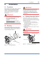
8.1 Overview............................................................................................................. 8-1
8.2
Calibration Instruments Selection................................................................... 8-1
8.3
Calibration.......................................................................................................... 8-1
8.4
Disassembly and Reassembly......................................................................... 8-3
8.5
9.
7.6.13
8.4.1
Replacing the Integral Indicator.......................................................... 8-3
8.4.2
Replacing the CPU Board Assembly.................................................. 8-4
8.4.3
Replacing the Process Connector Gasket....................................8-4
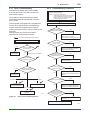
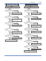
Troubleshooting................................................................................................. 8-4
8.5.1
Basic Troubleshooting........................................................................ 8-5
8.5.2
Troubleshooting Flowcharts................................................................ 8-5
8.5.3
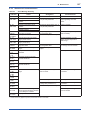
Alarms and Countermeasures............................................................ 8-7
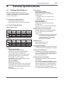
General Specifications............................................................................. 9-1
9.1
Standard Specifications.................................................................................... 9-1
9.2
Model and Suffix Codes.................................................................................... 9-4
9.3
Optional Specifications “◊”............................................................................ 9-11
9.4
Dimensions....................................................................................................... 9-13
Revision Information
When using the Transmitters in a Safety Instrumented Systems(SIS)
application, refer to Appendix A in either IM 01C25T01-06EN for the
HART protocol or IM 01C25T03-01E for the BRAIN protocol.
IM 01C25C01-01E
1.
1-1
<1. Introduction>
Introduction
Thank you for purchasing the DPharp Differential
Pressure transmitter.
Your Transmitter was precisely calibrated at the
factory before shipment. To ensure both safety and
efficiency, please read this manual carefully before
you operate the instrument.
NOTE
This manual describes the hardware
configurations of the transmitters listed in below.
For information on the software configuration
and operation, please refer to either
IM 01C25T03-01E for the BRAIN communication
type, or IM 01C25T01-06EN for the HART
communication type.
For FOUNDATION Fieldbus protocol type, please
refer to IM 01C25T02-01E.
For PROFIBUS PA protocol type, please refer to
IM 01C25T04-01EN.
Model
EJX210A
EJA210E
Style code
S2
S1
To ensure correct use of this instrument, read
both the hardware and software manuals
thoroughly before use.
WARNING
When using the transmitters in a Safety
Instrumented Systems (SIS) application, refer
to Appendix 1 in either IM 01C25T01-06EN for
the HART protocol or IM 01C25T03-01E for the
BRAIN protocol. The instructions and procedures
in this section must be strictly followed in order to
maintain the transmitter for this safety level.
NOTE
When describing the model name like
EJ210, it shows the applicability for both
EJX210A and EJA210E.
Regarding This Manual
• This manual should be provided to the end
user.
• The contents of this manual are subject to
change without prior notice.
• All rights reserved. No part of this manual may
be reproduced in any form without Yokogawa’s
written permission.
• Yokogawa makes no warranty of any kind with
regard to this manual, including, but not limited
to, implied warranty of merchantability and
fitness for a particular purpose.
• If any question arises or errors are found, or if
any information is missing from this manual,
please inform the nearest Yokogawa sales
office.
• The specifications covered by this manual are
limited to those for the standard type under the
specified model number break-down and do not
cover custom-made instruments.
• Please note that changes in the specifications,
construction, or component parts of the
instrument may not immediately be reflected
in this manual at the time of change, provided
that postponement of revisions will not cause
difficulty to the user from a functional or
performance standpoint.
• Yokogawa assumes no responsibility for this
product except as stated in the warranty.
• If the customer or any third party is harmed by
the use of this product, Yokogawa assumes
no responsibility for any such harm owing to
any defects in the product which were not
predictable, or for any indirect damages.
• The following safety symbols are used in this
manual:
WARNING
Indicates a potentially hazardous situation which,
if not avoided, could result in death or serious
injury.
IM 01C25C01-01E
CAUTION
Indicates a potentially hazardous situation which,
if not avoided, may result in minor or moderate
injury. It may also be used to alert against unsafe
practices.
IMPORTANT
Indicates that operating the hardware or software
in this manner may damage it or lead to system
failure.
NOTE
Draws attention to information essential for
understanding the operation and features.
Direct current
Functional grounding terminal
Caution
This symbol indicates that the operator must
refer to an explanation in the user’s manual
in order to avoid the risk of injury or death of
personnel or damage to the instrument.
1-2
<1. Introduction>
1.1 Safe Use of This Product
For the safety of the operator and to protect the
instrument and the system, please be sure to follow
this manual’s safety instructions when handling this
instrument. If these instructions are not heeded,
the protection provided by this instrument may be
impaired. In this case, Yokogawa cannot guarantee
that the instrument can be safely operated. Please
pay special attention to the following points:
(a) Installation
• This instrument may only be installed by an
engineer or technician who has an expert
knowledge of this device. Operators are not
allowed to carry out installation unless they
meet this condition.
• With high process temperatures, care must
be taken not to burn yourself by touching the
instrument or its casing.
• Never loosen the process connector nuts when
the instrument is installed in a process. This can
lead to a sudden, explosive release of process
fluids.
• When draining condensate from the pressure
detector section, take appropriate precautions
to prevent the inhalation of harmful vapors and
the contact of toxic process fluids with the skin
or eyes.
• When removing the instrument from a
hazardous process, avoid contact with the fluid
and the interior of the meter.
• All installation shall comply with local installation
requirements and the local electrical code.
(b) Wiring
• The instrument must be installed by an
engineer or technician who has an expert
knowledge of this instrument. Operators are not
permitted to carry out wiring unless they meet
this condition.
• Before connecting the power cables, please
confirm that there is no current flowing through
the cables and that the power supply to the
instrument is switched off.
IM 01C25C01-01E
(c) Operation
• Wait 10 min. after the power is turned off, before
opening the covers.
(d) Maintenance
• Please carry out only the maintenance
procedures described in this manual. If you
require further assistance, please contact the
nearest Yokogawa office.
• Care should be taken to prevent the build up of
dust or other materials on the display glass and
the name plate. To clean these surfaces, use a
soft, dry cloth.
(e) Explosion Protected Type Instrument
• Users of explosion proof instruments should
refer first to section 2.9 (Installation of an
Explosion Protected Instrument) of this manual.
• The use of this instrument is restricted to those
who have received appropriate training in the
device.
• Take care not to create sparks when accessing
the instrument or peripheral devices in a
hazardous location.
(f) Modification
• Yokogawa will not be liable for malfunctions or
damage resulting from any modification made
to this instrument by the customer.
<1. Introduction>
1-3
1.2 Warranty
• The warranty shall cover the period noted on
the quotation presented to the purchaser at the
time of purchase. Problems occurring during
the warranty period shall basically be repaired
free of charge.
• If any problems are experienced with this
instrument, the customer should contact the
Yokogawa representative from which this
instrument was purchased or the nearest
Yokogawa office.
• If a problem arises with this instrument,
please inform us of the nature of the problem
and the circumstances under which it
developed, including the model specification
and serial number. Any diagrams, data and
other information you can include in your
communication will also be helpful.
• The party responsible for the cost of fixing the
problem shall be determined by Yokogawa
following an investigation conducted by
Yokogawa.
• The purchaser shall bear the responsibility for
repair costs, even during the warranty period, if
the malfunction is due to:
- Improper and/or inadequate maintenance by
the purchaser.
- Malfunction or damage due to a failure
to handle, use, or store the instrument in
accordance with the design specifications.
- Use of the product in question in a location
not conforming to the standards specified by
Yokogawa, or due to improper maintenance
of the installation location.
- Failure or damage due to modification or
repair by any party except Yokogawa or an
approved representative of Yokogawa.
- Malfunction or damage from improper
relocation of the product in question after
delivery.
- Reason of force majeure such as fires,
earthquakes, storms/floods, thunder/
lightening, or other natural disasters, or
disturbances, riots, warfare, or radioactive
contamination.
IM 01C25C01-01E
<1. Introduction>
1-4
1.3 ATEX Documentation
This is only applicable to the countries in European Union.
GB
DK
SK
CZ
I
LT
E
LV
NL
EST
PL
SF
SLO
P
H
F
BG
D
RO
S
M
GR
IM 01C25C01-01E
2.
2-1
<2. Handling Cautions>
Handling Cautions
This chapter provides important information on how
to handle the transmitter. Read this carefully before
using the transmitter.
The transmitters are thoroughly tested at the
factory before shipment. When taking delivery of an
instrument, visually check them to make sure that
no damage occurred during shipment.
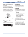
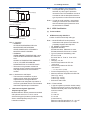
Also check that all transmitter mounting hardware
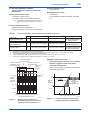
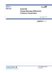
shown in figure 2.1 is included. If the transmitter
is ordered without the process connector, the
transmitter mounting hardware will not be included.
After checking the transmitter, carefully repack it in
its box and keep it there until you are ready to install
it.
2.2 Unpacking
Keep the transmitter in its original packaging to
prevent it from being damaged during shipment.
Do not unpack the transmitter until it reaches the
installation site.
2.3 Storage
The following precautions must be observed when
storing the instrument, especially for a long period.
(a) Select a storage area which meets the following
conditions:
• It is not exposed to rain or subject to water
seepage/leaks.
• Vibration and shock are kept to a minimum.
• It has an ambient temperature and relative
humidity within the following ranges.
Ambient temperature:
–40* to 85°C without integral indicator
–30* to 80°C with integral indicator
Process connector
* –15°C when /HE is specified.
Bolt
Process connector gasket
F0201.ai
Figure 2.1
Transmitter Mounting Hardware
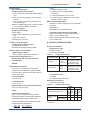
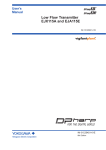
2.1 Model and Specifications
Check
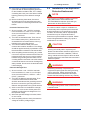
The model name and specifications are written on
the name plate attached to the case.
Relative humidity:
0% to 100% R.H. (at 40°C)
Preferred temperature and humidity:
approx. 25°C and 65% R.H.
(b) When storing the transmitter, repack it carefully
in the packaging that it was originally shipped
with.
(c) If the transmitter has been used, thoroughly
clean the chambers inside the cover flanges
and the diaphragm surface of high pressuredetector section, so that there is no process
fluid remaining inside or on it. Before placing it
in storage, also make sure that the pressuredetector is securely connected to the transmitter
section.
F0202.ai
Figure 2.2
Name Plate
IM 01C25C01-01E
2.4 Selecting the Installation
Location
The transmitter is designed to withstand severe
environmental conditions. However, to ensure
that it will provide years of stable and accurate
performance, take the following precautions when
selecting the installation location.
(a) Ambient Temperature
Avoid locations subject to wide temperature
variations or a significant temperature gradient.
If the location is exposed to radiant heat from
plant equipment, provide adequate thermal
insulation and/or ventilation.
(b) Ambient Atmosphere
Do not install the transmitter in a corrosive
atmosphere. If this cannot be avoided, there
must be adequate ventilation as well as
measures to prevent the leaking of rain water
and the presence of standing water in the
conduits.
(c) Shock and Vibration
Although the transmitter is designed to be
relatively resistant to shock and vibration, an
installation site should be selected where this is
kept to a minimum.
(d) Installation of Explosion-protected Transmitters
An explosion-protected transmitter is
certified for installation in a hazardous area
containing specific gas types. See subsection
2.9 “Installation of an Explosion-Protected
Transmitters.”
2.5 Pressure Connection
WARNING
• Never loosen the process connector and
flange bolts when an instrument is installed
in a process. The device is under pressure,
and a loss of seal can result in a sudden and
uncontrolled release of process fluid.
• When draining toxic process fluids that have
condensed inside the pressure detector,
take appropriate steps to prevent the contact
of such fluids with the skin or eyes and the
inhalation of vapors from these fluids.
2-2
<2. Handling Cautions>
The following precautions must be observed
in order to safely operate the transmitter under
pressure.
(a) Make sure that all the process connector bolts
are tightened firmly.
(b) Make sure that there are no leaks in the impulse
piping.
(c) Never apply a pressure higher than the
specified maximum working pressure.
2.6 Waterproofing of Cable
Conduit Connections
Apply a non-hardening sealant to the threads
to waterproof the transmitter cable conduit
connections. (See figure 6.8, 6.9 and 6.10.)
2.7 Restrictions on Use of Radio
Transceivers
IMPORTANT
Although the transmitter has been designed to
resist high frequency electrical noise, if a radio
transceiver is used near the transmitter or its
external wiring, the transmitter may be affected
by high frequency noise pickup. To test this, start
out from a distance of several meters and slowly
approach the transmitter with the transceiver
while observing the measurement loop for noise
effects. Thereafter use the transceiver outside
the range where the noise effects were first
observed.
2.8 Insulation Resistance and
Dielectric Strength Test
Since the transmitter has undergone insulation
resistance and dielectric strength tests at the factory
before shipment, normally these tests are not
required. If the need arises to conduct these tests,
heed the following:
(a) Do not perform such tests more frequently than
is absolutely necessary. Even test voltages that
do not cause visible damage to the insulation
may degrade the insulation and reduce safety
margins.
IM 01C25C01-01E
2-3
<2. Handling Cautions>
(b) Never apply a voltage exceeding 500 V DC
(100 V DC with an internal lightning protector)
for the insulation resistance test, nor a voltage
exceeding 500 V AC (100 V AC with an internal
lightning protector) for the dielectric strength
test.
(c) Before conducting these tests, disconnect
all signal lines from the transmitter terminals.
The procedure for conducting these tests is as
follows:
2.9 Installation of an ExplosionProtected Instrument
• Insulation Resistance Test
If a customer makes a repair or modification to
an intrinsically safe or explosionproof instrument
and the instrument is not restored to its original
condition, its intrinsically safe or explosionproof
construction may be compromised and the
instrument may be hazardous to operate. Please
contact Yokogawa before making any repair or
modification to an instrument.
1) Short-circuit the + and – SUPPLY terminals
in the terminal box. In case of 1 to 5 V output,
short-circuit the SUPPLY+, SUPPLY – and A
(VOUT +) terminals.
2) Turn OFF the insulation tester. Then connect
the insulation tester plus (+) lead wire to the
shorted SUPPLY terminals and the minus (–)
leadwire to the grounding terminal.
3) Turn ON the insulation tester power and
measure the insulation resistance. The voltage
should be applied as briefly as possible to verify
that the insulation resistance is at least 20 MΩ.
4) After completing the test and being very careful
not to touch exposed conductors disconnect the
insulation tester and connect a 100 kΩ resistor
between the grounding terminal and the shortcircuiting SUPPLY terminals. Leave this resistor
connected at least one second to discharge any
static potential. Do not touch the terminals while
it is discharging.
• Dielectric Strength Test
1) Short-circuit the + and – SUPPLY terminals
in the terminal box. In case of 1 to 5 V output,
short-circuit the SUPPLY+, SUPPLY – and A
(VOUT +) terminals.
2) Turn OFF the dielectric strength tester. Then
connect the tester between the shorted
SUPPLY terminals and the grounding terminal.
Be sure to connect the grounding lead of the
dielectric strength tester to the ground terminal.
3) Set the current limit on the dielectric strength
tester to 10 mA, then turn ON the power and
gradually increase the test voltage from ‘0’ to
the specified voltage.
4) When the specified voltage is reached, hold it
for one minute.
5) After completing this test, slowly decrease the
voltage to avoid any voltage surges.
NOTE
For FOUNDATION Fieldbus explosion protected
type, please refer to IM 01C22T02-01E.
For PROFIBUS PA explosion protected type,
please refer to IM 01C25T04-01EN.
CAUTION
This instrument has been tested and certified
as being intrinsically safe or explosionproof.
Please note that severe restrictions apply to this
instrument’s construction, installation, external
wiring, maintenance and repair. A failure to abide
by these restrictions could make the instrument a
hazard to operate.
WARNING
Maintaining the safety of explosionproof
equipment requires great care during mounting,
wiring, and piping. Safety requirements also
place restrictions on maintenance and repair.
Please read the following sections very carefully.
WARNING
The range setting switch must not be used in a
hazardous area.
IM 01C25C01-01E
IMPORTANT
For combined approval types
Once a device of multiple approval type is
installed, it should not be re-installed using any
other approval types. Apply a permanent mark
in the check box of the selected approval type
on the certification label on the transmitter to
distinguish it from unused approval types.
IMPORTANT
All the blind plugs which accompany the EJX/
EJA-E transmitters upon shipment from the
factory are certified by the applicable agency
in combination with the transmitters. The plugs
which are marked with the symbols “◊ Ex” on
their surfaces are certified only in combination
with the EJX/EJA-E series transmitters.
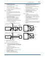
2.9.1 FM Approval
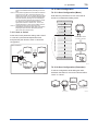
a. FM Intrinsically Safe Type
Caution for FM intrinsically safe type. (Following
contents refer “DOC. No. IFM022-A12”)
Note 1. Model EJX/EJA-E Series Differential,
gauge and absolute pressure transmitters
with optional code /FS1 are applicable for
use in hazardous locations.
• Applicable Standard: FM3600, FM3610,
FM3611, FM3810
• Intrinsically Safe for Class I, Division 1,
Groups A, B, C & D. Class II, Division 1,
Groups E, F & G and Class III, Division 1,
Class I, Zone 0 in Hazardous Locations, AEx
ia IIC
• Nonincendive for Class I, Division 2, Groups
A, B, C & D. Class II, Division 2, Groups F &
G, Class I, Zone 2, Groups IIC, in Hazardous
Locations.
• Outdoor hazardous locations, NEMA TYPE
4X.
• Temperature Class: T4
• Ambient temperature: –60 to 60°C
<2. Handling Cautions>
2-4
Note 2. Entity Parameters
• Intrinsically Safe Apparatus Parameters
[Groups A, B, C, D, E, F and G]
Vmax = 30 V
Ci = 6 nF
Imax = 200 mA
Li = 0 µH
Pmax = 1 W
* Associated Apparatus Parameters
(FM approved barriers)
Voc ≤ 30 V
Ca > 6 nF
Isc ≤ 200 mA
La > 0 µH
Pmax ≤ 1W
• Intrinsically Safe Apparatus Parameters
[Groups C, D, E, F and G]
Vmax = 30 V
Ci = 6 nF
Imax = 225 mA
Li = 0 µH
Pmax = 1 W
* Associated Apparatus Parameters
(FM approved barriers)
Voc ≤ 30 V
Ca > 6 nF
Isc ≤ 225 mA
La > 0 µH
Pmax ≤ 1 W
• Entity Installation Requirements
Vmax ≥ Voc or Uo or Vt, Imax ≥ Isc or Io or It,
Pmax (or Po) ≤ Pi, Ca or Co ≥ Ci + Ccable,
La or Lo ≥ Li + Lcable
Note 3. Installation
• Barrier must be installed in an enclosure that
meets the requirements of ANSI/ISA S82.01.
• Control equipment connected to barrier must
not use or generate more than 250 V rms or
V dc.
• Installation should be in accordance with
ANSI/ISA RP12.6 “Installation of Intrinsically
Safe Systems for Hazardous (Classified)
Locations” and the National Electric Code
(ANSI/NFPA 70).
• The configuration of associated apparatus
must be FMRC Approved.
• Dust-tight conduit seal must be used when
installed in a Class II, III, Group E, F and G
environments.
• Associated apparatus manufacturer’s
installation drawing must be followed when
installing this apparatus.
• The maximum power delivered from the
barrier must not exceed 1 W.
• Note a warning label worded
“SUBSTITUTION OF COMPONENTS MAY
IMPAIR INTRINSIC SAFETY,” and “INSTALL
IN ACCORDANCE WITH DOC. No. IFM022A12”
IM 01C25C01-01E
• Output signal: 4 to 20 mA
15 mA (FOUNDATION Fieldbus and
PROFIBUS PA type)
1 to 5 V (Low Power type)
Note 4. Maintenance and Repair
• The instrument modification or parts
replacement by other than authorized
representative of Yokogawa Electric
Corporation is prohibited and will void
Factory Mutual Intrinsically safe and
Nonincendive Approval.
[Intrinsically Safe]
Hazardous Location
Class I, II, III, Division 1,
Groups A, B, C, D, E, F, G
Class 1, Zone 0 in
Hazardous (Classified)
Locations AEx ia IIC
Pressure Transmitters
+
Supply
–
Nonhazardous Location
Safety Barrier
+
+
–
–
General
Purpose
Equipment
+
–
Note 2. Wiring
• All wiring shall comply with National Electrical
Code ANSI/NFPA70 and Local Electrical
Codes.
• When installed in Division 1, “FACTORY
SEALED, CONDUIT SEAL NOT
REQUIRED.”
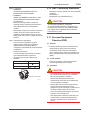
• Wiring connection for output signal code Q
(Low Power type) shall follow the diagram
below.
Pressure Transmitters
SUPPLY +
A
Voltmeter
F0203-1.ai
[Nonincendive]
Hazardous Location
Nonhazardous Location
Class I, II, Division 2,
Groups A, B, C, D, F, G
Class 1, Zone 2, Group IIC,
in Hazardous (Classified)
Locations
–
Power Supply
+
+
–
–
SUPPLY –
Three-Wire Connection
General
Purpose
Equipment
Pressure Transmitters
+
Supply
2-5
<2. Handling Cautions>
Pressure Transmitters
SUPPLY +
A
+
Not Use
Safety Barrier
–
F0203-2.ai
b. FM Explosionproof Type
Caution for FM explosionproof type.
Note 1. Model EJX/EJA-E Series pressure
transmitters with optional code /FF1 or
/V1F are applicable for use in hazardous
locations.
• Applicable Standard: FM3600, FM3615,
FM3810, ANSI/NEMA 250
• Explosionproof for Class I, Division 1,
Groups B, C and D.
• Dust-ignitionproof for Class II/III, Division 1,
Groups E, F and G.
• Enclosure rating: NEMA TYPE 4X.
• Temperature Class: T6
• Ambient Temperature: –40 to 60°C
• Supply Voltage: 42 V dc max.
32 V dc max. (FOUNDATION Fieldbus and
PROFIBUS PA type)
9 to 28 V dc, 27 mW (Low Power type)
Voltmeter
Power Supply
+
+
–
–
SUPPLY –
Four-Wire Connection
F0211.ai
Note 3. Operation
• Keep the “WARNING” nameplate attached to
the transmitter.
WARNING: OPEN CIRCUIT BEFORE
REMOVING COVER. FACTORY SEALED,
CONDUIT SEAL NOT REQUIRED.
INSTALL IN ACCORDANCE WITH THE
USERS MANUAL IM 01C25.
• Take care not to generate mechanical
sparking when accessing to the instrument
and peripheral devices in a hazardous
location.
Note 4. Maintenance and Repair
• The instrument modification or parts
replacement by other than authorized
representative of Yokogawa Electric
Corporation is prohibited and will void
Factory Mutual Explosionproof Approval.
IM 01C25C01-01E
c. FM Intrinsically Safe Type/FM
Explosionproof Type
Model EJX/EJA-E Series pressure transmitters
with optional code /FU1 or /V1U1 can be
selected the type of protection (FM Intrinsically
Safe or FM Explosionproof) for use in
hazardous locations.
Note 1. For the installation of this transmitter,
once a particular type of protection is
selected, any other type of protection
cannot be used. The installation must be in
accordance with the description about the
type of protection in this instruction manual.
Note 2. In order to avoid confusion, unnecessary
marking is crossed out on the label other
than the selected type of protection when
the transmitter is installed.
2.9.2 CSA Certification
a. CSA Intrinsically Safe Type
Caution for CSA Intrinsically safe and
nonincendive type. (Following contents refer to
“DOC No. ICS013-A13”)
Note 1. Model EJX/EJA-E Series differential,
gauge, and absolute pressure transmitters
with optional code /CS1 are applicable for
use in hazardous locations
Certificate: 1606623
[For CSA C22.2]
• Applicable Standard: C22.2 No.0, C22.2
No.0.4, C22.2 No.25, C22.2 No.94, C22.2
No.157, C22.2 No.213, C22.2 No.61010-1,
C22.2 No.60079-0
• Intrinsically Safe for Class I, Division 1,
Groups A, B, C & D, Class II, Division 1,
Groups E, F & G, Class III, Division 1
• Nonincendive for Class I, Division 2, Groups
A, B, C & D, Class II, Division 2, Groups F &
G, Class III, Division 1
• Enclosure: NEMA TYPE 4X
• Temp. Code: T4
• Amb. Temp.: –50* to 60°C
* –15°C when /HE is specified.
• Process Temperature: 120°C max.
[For CSA E60079]
• Applicable Standard: CAN/CSA E60079-11,
CAN/CSA E60079-15, IEC 60529:2001
• Ex ia IIC T4, Ex nL IIC T4
• Ambient Temperature: –50* to 60°C
2-6
<2. Handling Cautions>
Note 2. Entity Parameters
• Intrinsically safe ratings are as follows:
Maximum Input Voltage (Vmax/Ui) = 30 V
Maximum Input Current (Imax/Ii) = 200 mA
Maximum Input Power (Pmax/Pi) = 0.9 W
Maximum Internal Capacitance (Ci) = 10 nF
Maximum Internal Inductance (Li) = 0 µH
• Type "n" or Nonincendive ratings are as
follows:
Maximum Input Voltage (Vmax/Ui) = 30 V
Maximum Internal Capacitance (Ci) = 10 nF
Maximum Internal Inductance (Li) = 0 µH
• Installation Requirements
Uo ≤ Ui, Io ≤ Ii, Po ≤ Pi,
Co ≥ Ci + Ccable, Lo ≥ Li + Lcable
Voc ≤ Vmax, Isc ≤ Imax,
Ca ≥ Ci + Ccable, La ≥ Li + Lcable
Uo, Io, Po, Co, Lo, Voc, Isc, Ca and La are
parameters of barrier.
Note 3. Installation
• In any safety barreir used output current
must be limited by a resistor 'R' such that
Io=Uo/R or Isc=Voc/R.
• The safety barrier must be CSA certified.
• Input voltage of the safety barrier must be
less than 250 Vrms/Vdc.
• Installation should be in accordance with
Canadian Electrical Code Part I and Local
Electrical Code.
• Dust-tight conduit seal must be used when
installed in Class II and III environments.
• The instrument modification or parts
replacement by other than authorized
representative of Yokogawa Electric
Corporation and Yokogawa Corporation
of America is prohibited and will void
Canadian Standards Intrinsically safe and
nonincendive Certification.
[Intrinsically Safe]
Hazardous Location
Nonhazardous Location
Group IIC, Zone 0
Class I, II, III, Division 1,
Groups A, B, C, D, E, F, G
Pressure Transmitters
+
Supply
–
Safety Barrier
+
+
–
–
General
Purpose
Equipment
+
–
F0204-1.ai
* –15°C when /HE is specified.
• Max. Process Temp.: 120°C
• Enclosure: IP66/IP67
IM 01C25C01-01E
[Nonincendive]
Hazardous Location
Nonhazardous Location
Group IIC, Zone 2
Class I, II, Division 2,
Groups A, B, C, D, F, G
Class III, Division 1.
CSA Certified
Equipment
([nL] or
nonincendive)
Pressure Transmitters
+
Supply
2-7
<2. Handling Cautions>
–
+
Not Use
Safety Barrier
–
F0204-2.ai
b. CSA Explosionproof Type
Caution for CSA explosionproof type.
Note 1. Model EJX/EJA-E Series pressure
transmitters with optional code /CF1 or
/V1F are applicable for use in hazardous
locations:
• Certificate: 2014354
• Applicable Standard: C22.2 No.0, C22.2 No.0.4, C22.2 No.0.5,
C22.2 No.25, C22.2 No.30, C22.2 No.94,
C22.2 No.61010-1, C22.2 No.60079-0,
C22.2 No.60079-1
• Explosion-proof for Class I, Groups B, C and
D.
• Dustignition-proof for Class II/III, Groups E, F
and G.
• Enclosure: NEMA TYPE 4X
• Temperature Code: T6...T4
• Ex d IIC T6...T4 • Enclosure: IP66/IP67
• Maximum Process Temperature:
120°C (T4), 100°C (T5), 85°C (T6)
• Ambient Temperature: –50* to 75°C (T4),
–50* to 80°C (T5), –50* to 75°C (T6)
* –15°C when /HE is specified.
• Supply Voltage: 42 V dc max.
32 V dc max. (FOUNDATION Fieldbus and
PROFIBUS PA type)
9 to 28 V dc, 27 mW (Low Power type)
• Output Signal: 4 to 20 mA dc
15 mA (FOUNDATION Fieldbus and
PROFIBUS PA type)
1 to 5 V (Low Power type)
Note 2. Wiring
• All wiring shall comply with Canadian
Electrical Code Part I and Local Electrical
Codes.
• In hazardous location, wiring shall be in
conduit as shown in the figure.
• WARNING:
A SEAL SHALL BE INSTALLED WITHIN
50cm OF THE ENCLOSURE.
UN SCELLEMENT DOIT ÊTRE INSTALLÉ À
MOINS DE 50cm DU BOÎTIER.
• WARNING: WHEN INSTALLED IN CL.I, DIV 2, SEAL
NOT REQUIRED.
UNE FOIS INSTALLÉ DANS CL I, DIV 2,
AUCUN JOINT N'EST REQUIS.
Non-Hazardous Hazardous Locations Division 1
Locations
Non-hazardous
Location
50 cm Max.
Equipment
42 V DC Max.
4 to 20 mA DC
Signal
Sealing Fitting
Conduit
Transmitter
F0205-1.ai
Non-Hazardous Hazardous Locations Division 2
Locations
Non-hazardous
Location
Equipment
42 V DC Max.
4 to 20 mA DC
Signal
Sealing Fitting
Transmitter
F0205-2.ai
• All wiring shall comply with local installation
requirements and local electrical code.
• In hazardous locations, the cable entry
devices shall be of a certified flameproof
type, suitable for the conditions of use and
correctly installed.
• Unused apertures shall be closed with
suitable flameproof certified blanking
elements. (The plug attached is flameproof
certified.)
• Wiring connection for output signal code Q
(Low Power type) shall follow the diagram
below.
IM 01C25C01-01E
Pressure Transmitters
SUPPLY +
A
Voltmeter
Power Supply
+
+
–
–
SUPPLY –
Pressure Transmitters
A
Voltmeter
Power Supply
+
+
–
–
2.9.3 ATEX Certification
(1) Technical Data
a. ATEX Intrinsically Safe Ex ia
SUPPLY –
Four-Wire Connection
Note 1. For the installation of this transmitter,
once a particular type of protection is
selected, any other type of protection
cannot be used. The installation must be in
accordance with the description about the
type of protection in this instruction manual.
Note 2. In order to avoid confusion, unnecessary
marking is crossed out on the label other
than the selected type of protection when
the transmitter is installed.
Three-Wire Connection
SUPPLY +
2-8
<2. Handling Cautions>
Caution for ATEX Intrinsically safe type.
F0212.ai
Note 3. Operation
• WARNING:
AFTER DE-ENERGIZING, DELAY 5
MINUTES BEFORE OPENING.
APRÉS POWER-OFF, ATTENDRE 5
MINUTES AVANT D'OUVRIR.
• WARNING:
WHEN AMBIENT TEMPERATURE ≥ 65°C,
USE THE HEAT-RESISTING CABLES ≥
90°C.
QUAND LA TEMPÉRATURE AMBIANTE
≥ 65°C, UTILISEZ DES CÂBLES
RÉSISTANTES Á LA CHALEUR ≥ 90°C.
• Take care not to generate mechanical
sparking when accessing to the instrument
and peripheral devices in a hazardous
location.
Note 4. Maintenance and Repair
• The instrument modification or parts
replacement by other than authorized
representative of Yokogawa Electric
Corporation and Yokogawa Corporation of
America is prohibited and will void Canadian
Standards Explosionproof Certification.
c. CSA Intrinsically Safe Type/CSA
Explosionproof Type
Model EJX/EJA-E Series pressure transmitters
with optional code /CU1 or /V1U1 can be
selected the type of protection (CSA Intrinsically
Safe or CSA Explosionproof) for use in
hazardous locations.
Note 1. Model EJX/EJA-E Series pressure
transmitters with optional code /KS21 for
potentially explosive atmospheres:
• No. DEKRA 11ATEX0228 X
• Applicable Standard:
EN 60079-0:2009, EN 60079-11:2007,
EN 60079-26:2007, EN 61241-11:2006
• Type of Protection and Marking code:
Ex ia IIC T4 Ga
Ex ia IIIC T85 ºC T100 ºC T120 ºC Db
• Group: II
• Category: 1G, 2D
• Ambient Temperature for EPL Ga:
–50 to 60°C
• Ambient Temperature for EPL Db:
–30* to 60°C
* –15°C when /HE is specified.
• Process Temperature (Tp.): 120°C max.
• Maximum Surface Temperature for EPL Db:
T85°C (Tp.: 80°C)
T100°C (Tp.: 100°C)
T120°C (Tp.: 120°C)
• Enclosure: IP66 / IP67
Note 2 Electrical Data
• In type of explosion protection intrinsic safety
Ex ia IIC or Ex ia IIIC, only for connection to a
certified intrinsically safe circuit with following
maximum values:
Ui = 30 V
Ii = 200 mA
Pi = 0.9 W
(Linear Source)
Maximum internal capacitance; Ci = 27.6 nF
Maximum internal inductance; Li = 0 µH
IM 01C25C01-01E
Note 3. Installation
• Refer to the control drawing. All wiring shall
comply with local installation requirements.
[Control Drawing]
Hazardous Location
Nonhazardous Location
Transmitter
Supply
+
+
–
–
Safety Barrier *1
F0206.ai
2-9
<2. Handling Cautions>
*1: In any safety barriers used the output current must be
limited by a resistor “R” such that Io=Uz/R.
Note 4. Maintenance and Repair
• The instrument modification or parts
replacement by other than authorized
representative of Yokogawa Electric
Corporation is prohibited and will void
DEKRA Intrinsically safe Certification.
Note 5. Special Conditions for Safe Use
WARNING
• In the case where the enclosure of the
Pressure Transmitter is made of aluminium,
if it is mounted in an area where the use of
category 1 G apparatus is required, it must
be installed such, that, even in the event of
rare incidents, ignition sources due to impact
and friction sparks are excluded.
• Electrostatic charge may cause an exlosion
hazard. Avoid any actions that cause the
generation of electrostatic charge, such as
rubbing with a dry cloth on coating face of
the product.
• In case of the enclosure of the Pressure
Transmitter with paint layers, if it is mounted
in an area where the use of category 2D
apparatus is required, it shall be installed in
such a way that the risk from electrostatic
discharges and propagating brush
discharges caused by rapid flow of dust is
avoided.
• To satisfy IP66 or IP67, apply waterproof
glands to the electrical connection port.
• When the lightning protector option is
specified, the apparatus is not capable
of withstanding the 500V insulation test
required by EN60079-11. This must be taken
into account when installing the apparatus.
b. ATEX Flameproof Type
Caution for ATEX flameproof type.
Note 1. Model EJX/EJA-E Series pressure
transmitters with optional code /KF22 or
/V1F for potentially explosive atmospheres:
• No. KEMA 07ATEX0109 X
• Applicable Standard: EN 60079-0:2009,
EN 60079-1:2007, EN 60079-31:2009
• Type of Protection and Marking Code:
Ex d IIC T6...T4 Gb, Ex tb IIIC T85°C Db
• Group: II
• Category: 2G, 2D
• Enclosure: IP66 / IP67
• Temperature Class for gas-poof:
T6, T5, and T4
• Ambient Temperature for gas-proof:
–50 to 75°C (T6), –50 to 80°C (T5), and
–50 to 75°C (T4)
• Maximum Process Temperature (Tp.) for
gas-proof:
85°C (T6), 100°C (T5), and 120°C (T4)
• Maximum Surface Temperature for dustproof:
T85°C (Tamb.: –30* to 75°C, Tp.: 85°C)
* –15°C when /HE is specified.
Note 2. Electrical Data
• Supply voltage: 42 V dc max.
32 V dc max. (FOUNDATION Fieldbus and
PROFIBUS PA type)
9 to 28 V dc, 27 mW (Low Power type)
• Output signal: 4 to 20 mA
15 mA (FOUNDATION Fieldbus and
PROFIBUS PA type)
1 to 5 V (Low Power type)
IM 01C25C01-01E
Note 3. Installation
• All wiring shall comply with local installation
requirement.
• Cable glands, adapters and/or blanking
elements with a suitable IP rating shall
be of Ex d IIC/Ex tb IIIC certified by ATEX
and shall be installed so as to maintain the
specific degree of protection (IP Code) of the
equipment.
• Wiring connection for output signal code Q
(Low Power type) shall follow the diagram
below.
Pressure Transmitters
SUPPLY +
A
Voltmeter
Power Supply
+
+
–
–
SUPPLY –
Three-Wire Connection
Pressure Transmitters
SUPPLY +
A
2-10
<2. Handling Cautions>
Voltmeter
Power Supply
+
+
–
–
SUPPLY –
Four-Wire Connection
F0213.ai
Note 4. Operation
• WARNING: AFTER DE-ENERGIZING,
DELAY 5 MINUTES BEFORE OPENING.
WHEN THE AMBIENT TEMP.≥65°C, USE
HEAT-RESISTING CABLE AND CABLE
GLAND ≥90°C.
• Take care not to generate mechanical
sparking when accessing to the instrument
and peripheral devices in a hazardous
location.
Note 5. Special Conditions for Safe Use
WARNING
• Electrostatic charge may cause an explosion
hazard. Avoid any actions that cause the
generation of electrostatic charge, such as
rubbing with a dry cloth on coating face of the
product.
• In the case where the enclosure of the
Pressure Transmitter is made of aluminium,
if it is mounted in an area where the use of
category 2D apparatus is required, it shall
be installed in such a way that the risk from
electrostatic discharges and propagating
brush discharges caused by rapid flow of
dust is avoided.
• The instrument modification or parts
replacement by other than an authorized
Representative of Yokogawa Electric
Corporation is prohibited and will void the
certification.
c. ATEX Intrinsically Safe Type/ATEX
Flameproof Type
Model EJX/EJA-E Series pressure transmitters
with optional code /KU22 or /V1U1 can
be selected the type of protection ATEX
Flameproof, Intrinsically Safe. Ex ia, or Ex ic for
use in hazardous area.
Note 1. For the installation of this transmitter,
once a particular type of protection is
selected, any other type of protection
cannot be used. The installation must be in
accordance with the description about the
type of protection in this user’s manual.
Note 2. For combined approval types Once a
device of multiple approval type is installed,
it should not be re-installed using any
other approval types. Apply a permanent
mark in the check box of the selected
approval type on the certification label on
the transmitter to distinguish it from unused
approval types.
IM 01C25C01-01E
● ATEX Intrinsically Safe Ex ic
Note 4. Specific Conditions of Use
Caution for ATEX intrinsically safe Ex ic
• Applicable Standard:
EN 60079-0:2009/EN 60079-0:2012,
EN 60079-11:2012
• Type of Protection and Marking Code:
II 3G Ex ic IIC T4 Gc
• Ambient Temperature: –30* to +60°C
WARNING
* –15°C when /HE is specified.
• Ambient Humidity:
0 to 100% (No condensation)
• Maximum Process Temperature: 120°C
• IP Code: IP66
• Ambient pollution degree: 2
• Overvoltage category: I
A mark indicating the electrical connection type
is stamped near the electrical connection port.
These marks are as followed.
Note 2. Installation
• All wiring shall comply with local installation
requirements. (refer to the control drawing)
• Cable glands, adapters and/or blanking
elements shall be of Ex “n”, Ex “e” or Ex “d”
and shall be installed so as to maintain the
specified degree of protection (IP Code) of
the transmitters.
Note 3. Maintenance and Repair
• The instrument modification or parts
replacement by other than authorized
representative of Yokogawa Electric
Corporation is prohibited and will void ATEX
intrinsically safe.
[Control drawing]
Hazardous Area
• Electrostatic charge may cause an explosion
hazard. Avoid any actions that cause the
generation of electrostatic charge, such as
rubbing with a dry cloth on coating face of
the product.
• When the lightning protector option is
specified, the apparatus is not capable
of withstanding the 500V insulation test
required by EN60079-11. This must be taken
into account when installing the apparatus.
(2) Electrical Connection
Note 1. Electrical Data
Ui = 30 V
Ci = 27.6 nF
Li = 0 µH
+
Pressure
Transmitters –
2-11
<2. Handling Cautions>
Nonhazardous Area
Associated
Apparatus
Screw Size
ISO M20 × 1.5 female
ANSI 1/2 NPT female
Marking
M
N or
W
Location of the mark
F0208.ai
(3) Installation
WARNING
• All wiring shall comply with local installation
requirements and the local electrical code.
• There is no need for conduit seal in Division
1 and Division 2 hazardous locations
because this product is sealed at the factory.
F0207.ai
(4) Operation
WARNING
• OPEN CIRCUIT BEFORE REMOVING
COVER. INSTALL IN ACCORDANCE WITH
THIS USER’S MANUAL
• Take care not to generate mechanical
sparking when access to the instrument and
peripheral devices in a hazardous location.
IM 01C25C01-01E
2-12
<2. Handling Cautions>
(5) Maintenance and Repair
WARNING
The instrument modification or parts replacement
by other than an authorized Representative of
Yokogawa Electric Corporation is prohibited and
will void the certification.
*1: The first digit in the three numbers next to the nine
letters of the serial number appearing after “NO.”
on the nameplate indicates the year of production.
The following is an example of a serial number for a
product that was produced in 2010:
91K819857
032
The year 2010
*2: “180-8750” is a zip code which represents the
following address.
2-9-32 Nakacho, Musashino-shi, Tokyo Japan
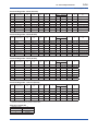
(6) Name Plate
2.9.4 IECEx Certification
Name plate
Model EJX Series pressure transmitters with
optional code /SU2 can be selected the type of
protection (IECEx Intrinsically Safe/type n or
flameproof) for use in hazardous locations.
Tag plate for flameproof type
No. KEMA 07ATEX0109 X
Ex d IIC T6...T4 Gb, Ex tb IIIC T85°C Db
Enlcosure : IP66/IP67
TEMP. CLASS
T6 T5
T4
MAX PROCESS TEMP.(Tp.)
85 100 120 °C
Tamb.
-50 to 75
80
75 °C
T85°C(Tamb.:-30(-15) to 75°C, Tp.:85°C)(for Dust)
D
*3
WARNING
AFTER DE-ENERGIZING, DELAY 5 MINUTES BEFORE
OPENING.
WHEN THE AMBIENT TEMP. ≥ 65°C, USE THE
HEAT-RESISTING CABLE & CABLE GLAND ≥ 90°C
POTENTIAL ELECTROSTATIC CHARGING HAZARD
Tag plate for intrinsically safe type
No. DEKRA 11ATEX 0228 X
Ex ia IIC T4 Ga Ta: -50 TO 60°C
Ex ia IIIC T85°C T100°C T120°C Db Ta:-30(-15) TO 60°C
IP66/IP67
MAX. PROCESS TEMP.(Tp.) 120°C
T85°C(Tp.:80°C), T100°C(Tp.:100°C), T120°C(Tp.:120°C)
Ui=30V, Ii=200mA , Pi=0.9W, Ci=27.6nF, Li=0µH
Note 1. For the installation of this transmitter,
once a particular type of protection is
selected, any other type of protection
cannot be used. The installation must be in
accordance with the description about the
type of protection in this instruction manual.
Note 2. In order to avoid confusion, unnecessary
marking is crossed out on the label other
than the selected type of protection when
the transmitter is installed.
a. IECEx Intrinsically Safe Type / type n
Caution for IECEx Intrinsically safe and type n.
Note 1. Model EJX Series differential, gauge,
and absolute pressure transmitters with
optional code /SU2 are applicable for use
in hazardous locations
• No. IECEx CSA 05.0005
• Applicable Standard: IEC 60079-0:2000,
IEC 60079-11:1999, IEC 60079-15:2001
• Ex ia IIC T4, Ex nL IIC T4
• Ambient Temperature: –50 to 60°C
• Max. Process Temp.: 120°C
• Enclosure: IP66/IP67
D
*3
*3: The identification number of Notified Body.
WARNING
POTENTIAL ELECTROSTATIC
CHARGING HAZARD
- SEE USER’S MANUAL
Tag plate for intrinsically safe Ex ic
Ex ic IIC T4 Gc
IP66
Tamb -30(-15) TO 60°C
MAX. PROCESS TEMP. 120°C
Ui=30V, Ci=27.6nF, Li=0µH
WARNING
POTENTIAL ELECTROSTATIC
CHARGING HAZARD
- SEE USER’S MANUAL
F0209.ai
MODEL: Specified model code.
STYLE: Style code.
SUFFIX: Specified suffix code.
SUPPLY: Supply voltage.
OUTPUT: Output signal.
MWP: Maximum working pressure.
CAL RNG: Specified calibration range.
NO.: Serial number and year of production*1.
TOKYO 180-8750 JAPAN:
The manufacturer name and the address*2.
Note 2. Entity Parameters
• Intrinsically safe ratings are as follows:
Maximum Input Voltage (Vmax/Ui) = 30 V
Maximum Input Current (Imax/Ii) = 200 mA
Maximum Input Power (Pmax/Pi) = 0.9 W
Maximum Internal Capacitance (Ci) = 10 nF
Maximum Internal Inductance (Li) = 0 µH
• Type "n" ratings are as follows:
Maximum Input Voltage (Vmax/Ui) = 30 V
Maximum Internal Capacitance (Ci) = 10 nF
Maximum Internal Inductance (Li) = 0 µH
IM 01C25C01-01E
• Installation Requirements
Uo ≤ Ui, Io ≤ Ii, Po ≤ Pi,
Co ≥ Ci + Ccable, Lo ≥ Li + Lcable
Voc ≤ Vmax, Isc ≤ Imax,
Ca ≥ Ci + Ccable, La ≥ Li + Lcable
Uo, Io, Po, Co, Lo, Voc, Isc, Ca and La are
parameters of barrier.
Note 3. Installation
• In any safety barrier used output current
must be limited by a resistor 'R' such that
Io=Uo/R.
• The safety barrier must be IECEx certified.
• Input voltage of the safety barrier must be
less than 250 Vrms/Vdc.
• The instrument modification or parts
replacement by other than authorized
representative of Yokogawa Electric
Corporation and will void IECEx Intrinsically
safe and type n certification.
[Intrinsically Safe]
Hazardous Location
Nonhazardous Location
Group IIC, Zone 0
Pressure Transmitters
+
Supply
IECEx certified
Safety Barrier
+
+
–
–
–
General
Purpose
Equipment
+
Nonhazardous Location
Group IIC, Zone 2
IECEx Certified
Equipment [nL]
Pressure Transmitters
+
–
Note 2. Wiring
• In hazardous locations, the cable entry
devices shall be of a certified flameproof
type, suitable for the conditions of use and
correctly installed.
• Unused apertures shall be closed with
suitable flameproof certified blanking
elements.
• Wiring connection for output signal code Q
(Low Power type) shall follow the diagram
below.
Pressure Transmitters
SUPPLY +
A
Voltmeter
Power Supply
+
+
–
–
SUPPLY –
Three-Wire Connection
[type n]
Hazardous Location
• Ambient Temperature: –50 to 75°C (T4),
–50 to 80°C (T5), –50 to 75°C (T6)
• Supply Voltage: 42 V dc max.
32 V dc max. (FOUNDATION Fieldbus and
PROFIBUS PA type)
9 to 28 V dc, 27 mW (Low Power type)
• Output Signal: 4 to 20 mA dc
15 mA (FOUNDATION Fieldbus and
PROFIBUS PA type)
1 to 5 V (Low Power type)
–
F0210-1.ai
Supply
2-13
<2. Handling Cautions>
Not Use
Safety Barrier
Pressure Transmitters
SUPPLY +
A
Voltmeter
Power Supply
+
+
+
–
–
–
SUPPLY –
F0210-2.ai
b. IECEx Flameproof Type
Four-Wire Connection
F0214.ai
Caution for IECEx flameproof type.
Note 1. Model EJX/EJA-E Series pressure
transmitters with optional code /SF2, /SU2
or /V1F are applicable for use in hazardous
locations:
• No. IECEx CSA 07.0008
• Applicable Standard: IEC60079-0:2011,
IEC60079-1:2007-4
• Flameproof for Zone 1, Ex d IIC T6...T4 Gb • Enclosure: IP66/IP67
• Maximum Process Temperature:
120°C (T4), 100°C (T5), 85°C (T6)
IM 01C25C01-01E
<2. Handling Cautions>
Note 3. Operation
• WARNING:
AFTER DE-ENERGIZING, DELAY 5
MINUTES BEFORE OPENING.
• WARNING: WHEN THE AMBIENT TEMP.≥65°C, USE
HEAT-RESISTING CABLE AND CABLE
GLAND ≥90°C.
• Take care not to generate mechanical
sparking when accessing to the instrument
and peripheral devices in a hazardous
location.
• Electrostatic charge may cause an explosion
hazard. Avoid any actions that cause the
generation of electrostatic charge, such as
rubbing with a dry cloth on coating face of the
product.
Note 4. Maintenance and Repair
• The instrument modification or parts
replacement by other than authorized
representative of Yokogawa Electric
Corporation is prohibited and will void IECEx
Certification.
• Electrical Connection
A mark indicating the electrical connection
type is stamped near the electrical
connection port. These marks are as
followed.
Screw Size
ISO M20 × 1.5 female
ANSI 1/2 NPT female
2.10 EMC Conformity Standards
EN61326-1 Class A, Table2 (For use in industrial
locations)
EN61326-2-3
EN61326-2-5 (for PROFIBUS only)
CAUTION
To meet EMC regulations, Yokogawa
recommends that customers run signal wiring
through metal conduits or use shielded twistedpair cabling when installing EJX/EJA-E series
transmitters in a plant.
2.11 Pressure Equipment
Directive (PED)
(1) General
• EJX/EJA-E Series pressure transmitters are
categorized as piping under the pressure
accessories section of directive 97/23/EC,
which corresponds to Article 3, Paragraph 3 of
PED, denoted as Sound Engineering Practice
(SEP).
(2) Technical Data
Article 3, Paragraph 3 of PED, denoted as
Sound Engineering Practice (SEP).
Marking
M
N or
2-14
(3) Operation
W
CAUTION
Location of the mark
F0215.ai
• The temperature and pressure of fluid should
be maintained at levels that are consistent
with normal operating conditions.
• The ambient temperature should be
maintained at a level that is consistent with
normal operating conditions.
• Please take care to prevent water hammer
and the like from inducing excessive
pressures in pipes and valves. If phenomena
are likely, install a safety valve or take
some other appropriate measure to prevent
pressure from exceeding PS.
• Take appropriate measures at the device or
system level to protect transmitters if they
are to be operated near an external heat
source.
IM 01C25C01-01E
<2. Handling Cautions>
2-15
2.12 Safety Requirement
Standards
Applicable standard : EN61010-1,
EN61010-2-30
(1) Pollution Degree 2
"Pollution degree" describes the degree to
which a solid, liquid, or gas which deteriorates
dielectric strength or surface resistivity is
adhering. " 2 " applies to normal indoor
atmosphere. Normally, only non-conductive
pollution occurs. Occasionally, however,
temporary conductivity caused by condensation
must be expected.
(2) Installation Category I
"Overvoltage category (Installation category)"
describes a number which defines a transient
overvoltage condition. It implies the regulattion
for impulse withstand voltage. " I " applies to
electrical equipment which is supplied from the
circuit when appropriate transient overvoltage
control means (interfaces) are provided.
(3) Altitude of installation site:
Max. 2,000 m above sea level
(4) Indoor/Outdoor use
IM 01C25C01-01E
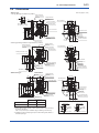
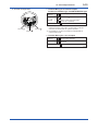
3.
3-1
<3. Component Names>
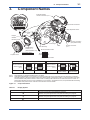
Component Names
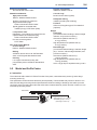
External indicator
conduit connection (Note 1)
Conduit connection
Zero-adjustment screw
Slide switch
(Note 2)
Integral
indicator (Note 1)
Mounting screw
Process connection
(low pressure side)
Cover flange
Range-setting
switch (Note 1)
(See Subsection 7.6)
Amplifier Cover
Transmitter section
Bolt
CPU assembly
Process connector
(Note 1)
Burnout direction switch
BO H
L
WR E
D
Write protection switch
Burnout direction switch (BO)
Burnout Direction
Switch Position
H
L
Hardware write protection switch (WR)
H
L
(Note 2)
Burnout Direction
Write Protection
Switch Position
(Note 2)
HIGH
LOW
Write Protection
H
L
H
L
E
D
E
D
NO
(Write enabled)
YES
(Write disabled)
F0301.ai
Note 1: See subsection 9.2, “Model and Suffix Codes,” for details.
Note 2: Applicable for BRAIN/HART communication type. Set the switches as shown in the figure above to set the burn-out direction
and write protection. The Burnout switch is set to the H side for delivery (unless option code /C1 or /C2 is specified in the order),
and the hardware write protection switch is set to E side. The setting of the switches can be confirmed via communication. An
external zero adjustment screw can only be disabled by communication. To disable the screw, set a parameter before activating
the hardware write protect function. See each communication manual for details.
Figure 3.1
Component Names
Table 3.1
Display Symbol
Display Symbol
Meaning of Display Symbol
The output signal being zero-adjusted is increasing.
Besides, this symbol lights when local parameter setting is in progress.
The output signal being zero-adjusted is decreasing.
Besides, this symbol lights when local parameter setting is in progress.
Write protect function is enabled.
F0302.ai
IM 01C25C01-01E
4.
4-1
<4. Installation>
Installation
4.1 Precautions
Before installing the transmitter, read the cautionary
notes in Section 2.4, “Selecting the Installation
Location.” For additional information on the
ambient conditions allowed at the installation
location, refer to Subsection 9.1 “Standard
Specifications.”
IMPORTANT
• When welding piping during construction,
take care not to allow welding currents to
flow through the transmitter.
• Do not step on this instrument after
installation.
• Never loosen the four bolts securing the
cover flanges (Refer to figure 3.1.) If the seal
liquid leaks, the transmitter cannot be used.
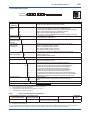
4.2 Mounting
The transmitter is mounted on a process using its
high-pressure side flange as shown in Figure 4.1.
The mating flange, gasket, stud bolts and nuts are
to be procured by the customer.
IMPORTANT
Please use a gasket with an inside diameter
(ød) that is greater than the diameter of the
diaphragm seal. If a gasket with a smaller
inside diameter is used, the diaphragm may
not function correctly. (Refer to Subsection 9.4
‘Dimensions’)
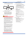
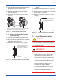
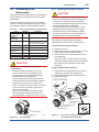
4.3 Rotating Transmitter Section
The transmitter section can be rotated in either
direction to any desired position. Note that there is
a stopper which prevents the transmitter from being
rotated more than 360°.
1) Using the Allen wrench, remove the two
setscrews securing the transmitter section to
the capsule assembly.
2) Rotate the transmitter section slowly to the
desired position.
3) Tighten the two setscrews to a torque of 1.5 N·m
{15 kgf·cm}.
IMPORTANT
Do not rotate the transmitter section more than
the above limit.
Transmitter section
Gasket
Rotate 180° segments
Conduit connection
Stud bolt
Nut
Figure 4.1
Pressure-detector section
F0402.ai
F0401.ai
Figure 4.2
Rotating Transmitter Section
Transmitter Mounting
IM 01C25C01-01E
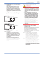
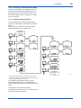
4.4 Changing Integral Indicator
Direction
IMPORTANT
• Always turn OFF power and shut off and
release pressures before disassembly.
• For changing the integral indicator direction,
the transmitter must be removed to a nonhazardous area.
An integral indicator can be installed in the following
three directions, Refer to subsection 8.4 for
attaching and removing the integral indicator.
F0403.ai
Figure 4.3
4-2
<4. Installation>
Integral Indicator Direction
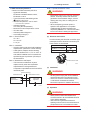
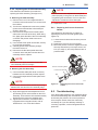
4.5 Mounting the Flushing
Connection Ring
4.5.1 Mounting to Pressure Detector
Section
The flushing connection ring is mounted to high
pressure side pressure detector section as shown
in Figure 4.4.
At the factory shipment, the flushing connection ring
is already assembled and attached to high pressure
side process detector section.
Pressure-detector section
Ring
Spiral gasket
Ring holder
Vent/Drain plug
Groove for installing
spiral gasket
View from pressure detector section side
F0404.ai
Figure 4.4
Mounting to Pressure Detector Section
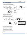
(1) Mount the ring holder on the ring and loosely
tighten the mounting screws.
(2) Place the spiral gasket in the ring groove. With
the ring correctly aligned and flush with the face
of the pressure detector, securely tighten each
ring holder’s mounting screws.
(3) Position the ring so that the vent/drain plugs are
aligned straight up and down.
IM 01C25C01-01E
4-3
<4. Installation>
4.5.2 Mounting to Process Flange
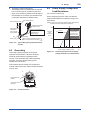
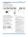
4.6 Affixing the Teflon Film
Tighten the bolts to completely close the gap
between the ring and the pressure detector section.
The FEP Teflon option includes a teflon film and
fluorinated oil. Before mounting the transmitter to
the process flange, affix the teflon film as follows:
The mating flange, gasket, stud bolts and nuts are
to be procured by the customer.
Spiral gasket
Mating flange
Ring
Diaphragm
Gasket
Pressure-detector
section
F0405.ai
Figure 4.5
Mounting to Process Flange
IMPORTANT
1) Position the diaphragm so that the
diaphragm is in a upward position.
2) Pour the fluorinated oil on the diaphragm
and gasket area covering it completely
and evenly. Be careful not to scratch the
diaphragm or change the its shape.
3) Affix the teflon film over the diaphragm and
gasket area.
4) Next, carefully inspect the cover and try
to identify any entrapped air between
the diaphragm and the teflon film. The
air must be removed to ensure optimum
performance. If air pockets are present, use
your fingers to remove the air by starting at
the center of the diaphragm and work your
way out.
5) Position the gasket on the Teflon film.
6) Mount the transmitter onto the process
flange.
IMPORTANT
Teflon film
• Confirm that there is no gap between the ring
and the process-detector section after they
are mounted on the process flange. A gap
can lead to a sudden, explosive release of
process fluids.
• When mounting or removing the ring,
take care not to tilt the pressure detector
downward as the ring can slip off and cause
injury.
• When re-mounting the ring, use the new
spiral gasket as shown in below table.
Table 4.1
Part number
F9350SV
F9970XF
F9350ST
F9970XD
F9346ZH
F9970XB
*:
**:
Fluorinated oil
[PART No. : F9145YN]
Diaphragm
Spiral Gasket for Pressure Detector
Section Side*
Size
ø100×ø120×t4.5
ø100×ø120×t4.5
ø70×ø90×t4.5
ø70×ø90×t4.5
ø60×ø75×t4.5
ø60×ø75×t4.5
Description
For 3-inch flange
For 3-inch flange**
For 2-inch flange
For 2-inch flange**
For 1 1/2-inch flange
For 1 1/2-inch flange**
Gasket area
Figure 4.6
PART No.
Prosess Flange size
F9347XA
3 inch (80mm)
F9347YD
2 inch (50mm)
F0406.ai
Affixing the Teflon Film
Material; 316SST (Hoop), PTFE Teflon (Filler)
For oil-prohibited use (Option code: /K1, /K2, /K5, /K6)
IM 01C25C01-01E
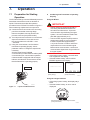
5.
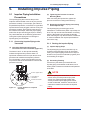
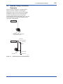
Installing Impulse Piping
5.1 Impulse Piping Installation
Precautions
The impulse piping that connects the process
outputs to the transmitter must convey the process
pressure accurately. If, for example, gas collects in
a liquid-filled impulse line, or the drain of a gas-filled
impulse line becomes plugged, it will not convey the
pressure accurately. Since this will cause errors in
the measurement output, select the proper piping
method for the process fluid (gas, liquid, or steam).
Pay careful attention to the following points when
routing the impulse piping and connecting the
impulse piping to a transmitter.
5.1.1 Connecting Impulse Piping to the
Transmitter
(1) Check the High and Low Pressure
Connections on the Transmitter (Figure 5.1)
The letters H and L on the capsule assembly
indicate the high and low pressure sides. For
liquid level measurement in an open tank, the low
pressure side measures atmospheric pressure.
For a closed tank, connect the impulse line to the
low pressure side of the transmitter to measure the
pressure in the tank.
H and L appear here
Low pressure
connection
Process connector
Bolt
F0501.ai
Figure 5.1
5-1
<5. Installing Impulse Piping>
H and L Symbols on a Capsule
Assembly
(2) Tightening the Process Connector
Mounting Bolts
After connecting the impulse line, tighten the
process connector mounting bolts uniformly.
(3) Removing the Impulse Piping Connecting
Port Dustproof Cap
The impulse piping connecting port of the
transmitter is covered with a plastic cap to keep out
dust. This cap must be removed before connecting
the line. (Be careful not to damage the threads
when removing this cap. Never insert a screwdriver
or other tool between the cap and port threads to
remove the cap.)
5.1.2 Routing the Impulse Piping
(1) Impulse Piping Slope
The impulse piping must be routed with only an
upward or downward slope. Even for horizontal
routing, the impulse piping should have a slope of
at least 1/10 to prevent condensate (or gases) from
accumulating in the pipes.
(2) Preventing Freezing
If there is any risk that the process fluid in the
impulse piping or transmitter could freeze, use a
steam jacket or heater to maintain the temperature
of the fluid.
NOTE
After completing the connections, close the
valves on the process pressure taps (main
valves), the valves at the transmitter (stop
valves), and the impulse piping drain valves,
so that condensate, sediment, dust and other
extraneous material cannot enter the impulse
piping.
IM 01C25C01-01E
<5. Installing Impulse Piping>
5-2
5.2 Impulse Piping Connection
Examples
Figure 5.2 shows examples of typical impulse
piping connections. Before connecting the
transmitter to the process, study the transmitter
installation location, the process piping layout,
and the characteristics of the process fluid
(corrosiveness, toxicity, flammability, etc.), etc. and
make appropriate changes and additions to the
connection configurations.
Open Tank
Pipe (opened to atmosphere
at low pressure side)
Closed Tank
Tap valve
Union or flange
Vent plug
Tee
Drain valve
Drain plug
F0502.ai
Figure 5.2
Impulse Piping Connection Examples
IM 01C25C01-01E
6.
6-1
<6. Wiring>
Wiring
6.1 Wiring Precautions
IMPORTANT
• Lay wiring as far as possible from electrical
noise sources such as large capacity
transformers, motors, and power supplies.
• Remove the electrical connection dust cap
before wiring.
• All threaded parts must be treated with
waterproofing sealant. (A non-hardening
silicone group sealant is recommended.)
• To prevent noise pickup, do not pass signal
and power cables through the same ducts.
• Explosion-protected instruments must
be wired in accordance with specific
requirements (and, in certain countries,
legal regulations) in order to preserve the
effectiveness of their explosion-protected
features.
• The terminal box cover is locked by an
Allen head bolt (a shrouding bolt) on ATEX
flameproof type transmitters. When the
shrouding bolt is driven clockwise using
an Allen wrench, it goes in. The cover lock
can then be released and the cover can
be opened by hand. See subsection 8.4
“Disassembly and Reassembly” for details.
• Plug and seal an unused conduit connection.
6.2 Selecting the Wiring
Materials
(a) Use stranded leadwires or cables which are
the same as or better than 600 V grade PVC
insulated wire (JIS C3307) or its equivalent.
(b) Use shielded wires in areas that are susceptible
to electrical noise.
(c) In areas with higher or lower ambient
temperatures, use appropriate wires or cables.
(d) In environment where oils, solvents, corrosive
gases or liquids may be present, use wires or
cables that are resistant to such substances.
(e) It is recommended that crimp-on solderless
terminal lugs (for 4 mm screws) with insulating
sleeves be used for leadwire ends.
6.3 Connections of External
Wiring to Terminal Box
● Terminal Configuration
Terminal
Terminal
1
Terminal
3
2
F0613.ai
● Terminal Wiring for 4 to 20 mA output,
FOUNDATION Fieldbus type, and
PROFIBUS PA type.
+
SUPPLY –
1
2
Power supply and output terminals
+
–
3
2
+
–
3
2
External indicator (ammeter) terminals*1*2
or
Status contact output terminals*2
(when /AL is specified)
CHECK
or
ALARM
Ground terminal
*1: When using an external indicator or check meter, the
internal resistance must be 10 Ω or less. A check meter
or indicator cannot be connected when /AL option is
specified.
*2: Not available for FOUNDATION Fieldbus and PROFIBUS
PA communication types.
● Terminal Wiring for 1 to 5 V output
+
SUPPLY –
1
2
Power supply terminals
+
–
3
2
1 to 5 V DC with HART communication
terminals
VOUT
Ground terminal
F0614.ai
Figure 6.1
Terminal
IM 01C25C01-01E
6-2
<6. Wiring>
6.3.1 Power Supply Wiring Connection
6.3.3 Communicator Connection
■ 4 to 20 mA output, BRAIN / HART
IMPORTANT
IMPORTANT
Connecting with the commercial AC power
supply will damage the device. Be sure to use
the DC power supply in the predetermined
range.
Connect the power supply wiring to the SUPPLY +
and – terminals. When /AL is specified, also refer to
subsection 6.3.5.
Power supply
+
Transmitter terminal box
Analog output may change temporally in
connecting with BRAIN terminal due to an initial
current flowed to it. To prevent communication
signal affecting the upper system, it is
recommended to install a low-pass filter
(approximately 0.1s)
Connect the BT200 or HART Communicator to the
SUPPLY + and – terminals. (Use hooks.)
Transmitter terminal box
–
Load resistance is not
necessary for 1 to 5 V output.
Figure 6.2
–
F0601.ai
Power Supply Wiring Connection
6.3.2 External Indicator Connection
Ignore the polarity since the
BT200 is AC-coupled to the
terminal box.
BT200
Available only for 4 to 20mA output type and when
/AL is not specified.
Connect wiring for external indicators to the CHECK
(+) and SUPPLY – terminals.
(Note)Use a external indicator whose internal resistance is 10 Ω
or less.
External indicator
Power supply
Power supply
+
F0603.ai
Figure 6.4
BT200 Connection
■ 1 to 5 V output, HART
Connect the HART communicator or configuration
tool to the SUPPLY - and VOUT (+) terminals. (Use
hooks.)
Power supply
+
Transmitter terminal box
+
USB
FieldMate Modem
–
+
Voltmeter
–
–
PC/FieldMate
Transmitter terminal box
Figure 6.3
External Indicator Connection
F0602.ai
Figure 6.5
Four wire connection
Transmitter terminal box
USB
FieldMate Modem
PC/FieldMate
Figure 6.6
F0615.ai
Power supply
+
–
+
Voltmeter
–
F0616.ai
Three wire connection
IM 01C25C01-01E
6-3
<6. Wiring>
6.3.4 Check Meter Connection
6.4 Wiring
Available only for 4 to 20mA output type and when
/AL is not specified.
6.4.1 Loop Configuration
Connect the check meter to the CHECK A (+) and
SUPPLY – terminals. (Use hooks.)
Since the DPharp uses a two-wire transmission
system for 4 to 20 mA output, signal wiring is also
used as power wiring.
• A 4 to 20 mA DC output signal from the CHECK
A (+) and SUPPLY – terminals.
(Note)Use a check meter whose internal resistance is 10 Ω or
less.
Check meter
Transmitter terminal box
Power supply
+
–
For 1 to 5 V output, three or four wire system is
used. See (3).
F0604.ai
Figure 6.7
DC power is required for the transmitter loop. The
transmitter and distributor are connected as shown
below.
For details of the power supply voltage and load
resistance, see section 6.6; for communications line
requirements, see section 9.1.
Check Meter Connection
(1) 4 to 20 mA output, General-use Type and
Flameproof Type
Hazardous Location
Transmitter terminal box
6.3.5 Status Output Connection
When option code /AL is specified, connect the
external wiring as shown in Figure 6.5.
To configure and activate the process alarm
function and status output, it is necessary to set
some parameters. Refer to each communication
manual for procedures.
Transmitter
terminal box Shielded cable
Nonhazardous Location
Distributor
(Power supply unit)
Receiver
instrument
F0606.ai
Figure 6.9
Connection between Transmitter and
Distributor
24V DC
+
–
250Ω
With the intrinsically safe type, a safety barrier must
be included in the loop.
Magnetic
valve
External power
supply 30V DC,
120mA max
Use two-wire separately shielded cables.
(2) 4 to 20 mA output, Intrinsically Safe Type
Distributor
Hazardous Location
Transmitter terminal box
AC power supply
Nonhazardous Location
Distributor
(Power supply unit)
F0605.ai
Figure 6.8
Status Output Connection
Receiver
instrument
Safety barrier
F0607.ai
Figure 6.10 Connection between Transmitter and
Distributor
IM 01C25C01-01E
6.4.2 Wiring Installation
(3) 1 to 5 V output
Either three or four wire system is used.
Power supply line and 1 to 5 V signal line commonly
use the SUPPLY - terminal.
NOTE
With three wire connection, the cable length
may affect the measurement accuracy of the
output signal. In either three-wire or four-wire
connection, recommended wiring distance is
200 m or less, and the use of shielded cable is
recommended.
■ Three wire connection
For three wire system, a negative wiring shall
be commonly used for power supply and signal
line.
Hazardous Location
Transmitter terminal box
6-4
<6. Wiring>
Nonhazardous Location
Distributor
(Power supply unit)
(1) General-use Type and Intrinsically Safe
Type
With the cable wiring, use a metallic conduit or
waterproof glands.
• Apply a non-hardening sealant to the terminal
box connection port and to the threads on the
flexible metal conduit for waterproofing.
Flexible metal conduit
Wiring metal
conduit
Apply a non-hardening
sealant to the threads for
waterproofing.
Tee
Drain plug
F0608.ai
Figure 6.13 Typical Wiring Using Flexible Metal
Conduit
(2) Flameproof Type
Wire cables through a flameproof packing adapter,
or use a flameproof metal conduit.
Receiver
instrument
F0617.ai
Figure 6.11 Connection between Transmitter,
Distributer and Receiver
■ Four wire connection
Fasten the negative side wiring of both power
supply and signal line to the SUPPLY - terminal.
Hazardous Location
Transmitter terminal box
■ Wiring cable through flameproof packing
adapter.
• Apply a non-hardening sealant to the terminal
box connection port and to the threads on the
flameproof packing adapter for waterproofing.
Flameproof packing
adapter
Flexible metal conduit
Wiring metal
conduit
Nonhazardous Location
Apply a non-hardening
sealant to the threads for
waterproofing.
Tee
Distributor
(Power supply unit)
Drain plug
F0609.ai
Figure 6.14 Typical Cable Wiring Using Flameproof
Packing Adapter
Receiver
instrument
F0618.ai
Figure 6.12 Connection between Transmitter,
Distributer and Receiver
IM 01C25C01-01E
■ Flameproof metal conduit wiring
• A seal fitting must be installed near the terminal
box connection port for a sealed construction.
• Apply a non-hardening sealant to the threads of
the terminal box connection port, flexible metal
conduit and seal fitting for waterproofing.
Non-hazardous area
Gas sealing device
Hazardous area
Flameproof
heavy-gauge
steel conduit
Drain plug
6.6 Power Supply Voltage and
Load Resistance
For 4 to 20 mA output only.
When configuring the loop, make sure that the
external load resistance is within the range in the
figure below.
(Note)In case of an intrinsically safe transmitter, external load
resistance includes safety barrier resistance.
Flameproof flexible
metal conduit
Tee
6-5
<6. Wiring>
Apply a non-hardening
sealant to the threads of
these fittings for
waterproofing
Seal fitting
After wiring, impregnate the fitting
with a compound to seal tubing.
600
External
load
resistance
R (Ω)
R=
E–10.5
0.0244
Communication
applicable range
BRAIN and HART
250
F0610.ai
Figure 6.15 Typical Wiring Using Flameproof Metal
Conduit
0
10.5
16.6
25.2
42
Power supply voltage E (V DC)
6.5 Grounding
Grounding is always required for the proper
operation of transmitters. Follow the domestic
electrical requirements as regulated in each
country. For a transmitter with a built-in lightning
protector, grounding should satisfy ground
resistance of 10Ω or less.
F0612.ai
Figure 6.17 Relationship between Power Supply
Voltage and External Load Resistance
Ground terminals are located on the inside and
outside of the terminal box. Either of these terminals
may be used.
Ground terminal
(inside)
Ground terminal
(outside)
F0611.ai
Figure 6.16 Ground Terminals
IM 01C25C01-01E
7.
7-1
<7. Operation>
Operation
7.1 Preparation for Starting
Operation
■
The EJ210 flange mounted differential pressure
transmitter measures the levels or densities of
liquids. This section describes the operation
procedure for the EJ210 as shown in Figure 7.1
when measuring a liquid level in an open tank.
Using the BT200
(a) Confirm that there is no leak in the connecting
part of the transmitter mounting flange.
Remove the plastic dust cap placed in the
process connector (low pressure side).
(b) Turn ON power and connect the communicator.
Open the terminal box cover and connect
the communicator to the SUPPLY + and
– terminals.
(c) Using the communicator, confirm that the
transmitter is operating properly. Check
parameter values or change the setpoints as
necessary.
See IM 01C25T03-01E (BRAIN
communication) or IM 01C25T01-06EN (HART
communication) for communicator operation.
If the transmitter is equipped with an integral
indicator, its indication can be used to confirm
that the transmitter is operating properly.
Confirming that Transmitter is Operating
Properly
IMPORTANT
• Analog output may change temporally in
connecting with BRAIN terminal due to
an initial current flowed to it. To prevent
communication signal affecting the upper
system, it is recommended to install a lowpass filter (approximately 0.1s).
• Communication signal is superimposed on
analog output signal. It is recommended
to set a low-pass filter (approximately
0.1s) to the receiver in order to reduce the
output effect from communication signal.
Before online-communication, confirm that
communication signal does not give effect on
the upper system.
• If the wiring system is faulty, ‘communication
error’ appears on the display.
• If the transmitter is faulty, ‘SELF CHECK
ERROR’ appears on the display.
PARAM
C60:SELF CHECK
ERROR
communication error
Open Tank
DATA
Communication error
(Faulty wiring)
DIAG
PRNT
Self-diagnostic error
(Faulty transmitter)
ESC
F0702.ai
Using the integral indicator
F0701.ai
Figure 7.1
Liquid Level Measurement
• If the wiring system is faulty, the display stays
blank.
• If the transmitter is faulty, an error code is
displayed.
Self-diagnostic error on the integral indicator
(Faulty transmitter)
F0703.ai
IM 01C25C01-01E
NOTE
If any of the above errors are indicated on
the display of the integral indicator or the
communicator, refer to subsection 8.5.3 for
corrective action.
■
7-2
<7. Operation>
To check the output signal, use a digital multimeter,
calibrator, or communicator.
(1) When you can obtain Low Range Value
from actual measured value of 0% (0 kPa,
atmospheric pressure);
Verify and Change Transmitter Parameter
Setting and Values
The parameters related to the following items are
set at factory as specified by the customer.
• Calibration range
• Integral indicator display
• Output mode
• Software damping (optional)
Other parameters like following are shipped with the
default setting.
• Low-cut
• Process alarm setting
• Static pressure range
• Signal characterizer
• Write protection
To confirm or change the values, see IM 01C25T0106EN or 01C25T03-01E.
7.2 Zero Point Adjustment
After completing preparations for operating the
transmitter, adjust the zero point.
Zero point adjustment can be done by turning the
transmitter’s zero-adjustment screw or by using
the communicator. This section describes the
procedure for the zero-adjustment screw. For the
communicator procedure, see the communication
manual.
IMPORTANT
Do not turn off the power to the transmitter
immediately after performing a zero point
adjustment. Powering off within 30 seconds of
performing this procedure will return the zero
point to its previous setting.
NOTE
Before performing this adjustment, make sure
that the external zero adjustment function has
NOT been disabled by a parameter setting.
Zero-adjustment
screw cover
F0704.ai
The zero-adjustment screw is located inside the
cover.
Use a slotted screwdriver to turn the zeroadjustment screw. Turn the screw clockwise
to increase the output or counterclockwise to
decrease the output. The zero point adjustment can
be made with a resolution of 0.01% of the setting
range. The degree of zero adjustments varies with
the screw turning speed; turn the screw slowly to
make a fine adjustment, quickly to make a rough
adjustment.
When adjusting the transmitter zero point, the
liquid level in a tank does not have to be set to
the low limit (0%) of the measuring range; use a
digital manometer or a glass gauge to match the
transmitter output signal with the actual measured
value.
(2) When you cannot obtain Low Range Value
from actual measured value of 0%;
Adjust the transmitter output to the actual measured
value obtained by a digital manometer or a glass
gauge.
[Example]
The measuring range of 50 to 250 kPa; the actual
measured value of 130 kPa.
Actual measured value=
130–50
x100=40.0%
250–50
(=10.4mA)
Turn the screw to match the output signal to the
actual measured value.
IM 01C25C01-01E
7.3 Starting Operation
After completing the zero point adjustment, follow
the procedure below to start operation.
1) Confirm the operating status. If the output
signal exhibits wide fluctuations (hunting) due to
periodic variation in the process pressure, use
the communicator to dampen the transmitter
output signal. Confirm the hunting using a
receiving instrument or the integral indicator,
and set the optimum damping time constant.
2) After confirming the operating status, perform
the following:
IMPORTANT
• Remove the communicator from the terminal
box, and confirm that none of the terminal
screws are loose.
• Close the terminal box cover and the
amplifier cover. Screw each cover in tightly
until it will not turn further.
• There are two covers that must be locked
on the ATEX Flameproof type transmitters.
An Allen head bolt (shrouding bolt) under
the edge of each cover is used to lock the
cover. When the shrouding bolt is driven
counterclockwise with an Allen wrench, the
bolt rotates upward and locks the cover. (See
page 8-3.) After locking the covers, confirm
that they are secure and cannot be opened
by hand.
• Tighten the zero-adjustment cover mounting
screw to fix the cover in position.
7.4 Shutting Down Operation
Turn off the power.
NOTE
7-3
<7. Operation>
7.5 Venting or Draining
Transmitter Pressuredetector Section
Since this transmitter is designed to be selfdraining and self-venting with vertical impulse
piping connections, neither draining nor venting
will be required if the impulse piping is configured
appropriately for self-draining or self-venting
operation.
If condensate (or gas) collects in the transmitter
pressure-detector section, the measured pressure
may be in error. If it is not possible to configure the
piping for self-draining (or self-venting) operation,
you will need to loosen the drain (vent) screw on the
transmitter to completely drain (vent) any stagnated
liquid (gas).
However, since draining condensate or bleeding off
gas gives the pressure measurement disturbance,
this should not be done when the loop is in
operation.
WARNING
Since the accumulated liquid (or gas) may be
toxic or otherwise harmful, take appropriate care
to avoid contact with the body, or inhalation of
vapors.
7.5.1 Draining Condensate
1) Gradually open the drain plug and drain the
transmitter pressure-detector section.
(See Figure 7.2)
2) When all accumulated liquid is completely
removed, close the drain plug.
3) Tighten the drain plug to a torque of 34 to 39
N·m {3.5 to 4 kgf·m}.
Whenever shutting down the transmitter for a
long period, detach the transmitter from the tank.
IM 01C25C01-01E
7-4
<7. Operation>
7.5.2 Venting Gas
1) Gradually open the vent screw to vent gas from
the transmitter pressur-detector section.
(See Figure 7.2)
2) When the transmitter is completely vented,
close the vent screw.
3) Tighten the vent screw to a torque of 10 N·m
{1 kgf·m}.
7.5.4 Venting Gas for Flushing Connection
Ring
1) Gradually open the vent screw to vent gas from
the flushing connection ring.
2) When the flushing connection ring is completely
vented, close the vent screw.
3) Tighten the vent screw to a torque of 10 N·m
{1 kgf·m}.
Vent screw
When you loosen the vent screw,
the accumulated liquid(or drain)
will be expelled in the direction
of the arrow.
Drain plug
Vent screw
When you loosen the drain plug or the vent screw, the accumulated
liquid (or gas) will be expelled in the direction of the arrow.
F0705.ai
Figure 7.2
Draining/Venting the Transmitter
7.5.3 Draining Condensate for Flushing
Connection Ring
1) Gradually open the drain screw to drain from
the flushing connection ring.
2) When the flushing connection ring is completely
drained, close the drain screw.
3) Tighten the drain screw to a torque of 10 N·m
{1 kgf·m}.
When you loosen the drain screw,
the accumulated liquid(or gas)
will be expelled in the direction of
the arrow.
Drain screw
F0706.ai
Figure 7.3
Draining for Flushing Connection Ring
F0707.ai
Figure 7.4
Venting for Flushing Connection Ring
7.6 Local Parameter Setting
WARNING
The local push button on the integral indicator
must not be used in a hazardous area. When it is
necessary to use the push button, operate it in a
non- hazardous location.
IMPORTANT
• Do not turn off the power to the transmitter
immediately after performing parameter
setting. Powering off within 30 seconds of
performing this procedure will return the
parameter to its previous setting.
• The parameter of Ext SW must be“Enabled”
to perform this configuration. See the user’s
manual IM 01C25T (HART/BRAIN) for the
setting procedure.
• The Local Parameter Setting function
is available with HART or BRAIN
communication type.
LCD update will be slower at low ambient
temperature, and it is recommended to use
LPS function at temperatures above -10
degrees C.
IM 01C25C01-01E
<7. Operation>
7-5
7.6.1 Local Parameter Setting (LPS)
Overview
Parameter configuration by the external adjustment
screw and push button (integral indicator code E)
offers easy and quick setup for parameters of Tag
number, Unit, LRV, URV, Damping,Output mode
(linear/square root), Display out 1, and Re-range
by applying actual pressure (LRV/URV). There is
no effect on measurement signal (analog output
or communication signal) when Local Parameter
Setting is carried out.
Integral indicator
External adjustment
screw cover
Push-button
F0708.ai
Figure 7.5
F0709.ai
External Adjustment Screw
Figure 7.6
Range –Setting Switch (push button)
screw
Process
Measurement
Display
push
Save/Cancel the value
Select Press unit
Save/Cancel the value
Edit Press LRV
Save/Cancel the value
Edit Press URV
Save/Cancel the value
Edit Damping time
Save/Cancel the value
Select Output mode
Save/Cancel the value
Edit Display Out1
Save/Cancel the value
8. LRV-Apply Press
Set LRV
Save/Cancel the value
9. URV-Apply Press
Set URV
Save/Cancel the value
10. Device Information
8, 9 : Re-range by applying actual pressure
10 : Displayed when output signal code is Q.
3. Press LRV
4. Press URV
5. Damping Time
6. Output Mode
push
push
*
Edit Tag number
2. Press Unit
push
push
Activate LPS mode
1. Tag Number
push
Zero adjustment
7. Display Out1
Process
Measurement
Display
*
*
*
*
*
*
F0710.ai
*:Note that the above 1 to 7 parameter configurations are available with the software revision (SOFT REV)2.03 or later.
Software revision can be checked via a field communicator (HART/BRAIN) or DTM. Please refer to IM 01C25T01 for HART parameter
“Software rev” and IM 01C25T03 for BRAIN “SOFT REV”.
Figure 7.7
IM 01C25C01-01E
<7. Operation>
7-6
7.6.2 Activating Local Parameter Setting
Press the push button on the integral indicator to
activate the Local Parameter Setting mode. The
transmitter will exit automatically from the Local
Parameter Setting mode if no operation is carried
out for 10 minutes.
7.6.3 Parameter Setting Review
Current setting value for the below parameters
are shown sequentially by each press of the push
button.
Tag number, Unit, LRV, URV, Damping,Output
mode (linear/square root), Display out 1.
Process
Measurement
Display
push
*
push
push
push
push
push
push
push
push
Process
Measurement
Display
F0711.ai
*:Up to 6 characters are shown in the bottom line. To review
after the 7th character, turn the external adjustment screw and
press the push button six times or more.
To configure each parameter value, turn the
external adjustment screw on each parameter
screen after activating the Local Parameter Setting
mode.
To cancel the Local Parameter Setting
configuration, please refer to 7.6.11 Save or Cancel
and 7.6.12 Abort Configuration.
IM 01C25C01-01E
<7. Operation>
7-7
7.6.4 TagNumberConfiguration
Tag Number is edited by turning the external
adjustmentscrew.Upto8alphanumericcharacters
for HART or 16 alphanumeric characters for BRAIN
can be set.
Save ?/
Cancel ?
Blinking
Blinking
Change the first Character
Go to the next Character
Set all other
characters in the
same way
screw
push
F0712.ai
7.6.5 PressureUnitConfiguration
Pressure unit for the below table can be changed
asbelow.Byturningtheexternaladjustmentscrew,
user can scroll between the various available
pressure units.
Save ?/
Cancel ?
Blinking
Blinking
Select by the push button
screw
push
[Available pressure units]
kPa bar
Torr mbar
atm
g/cm2
MPa kg/cm2
hPa Pa
mmHg
psi
inH2O@4degC(39.2degF)
inH2O@20degC(68degF)
inHg
ftH2O@4degC(39.2degF)
ftH2O@20degC(68degF)
mmH2O@4degC(39.2degF)
mmH2O@20degC(68degF)
In addition to the above units, mmAq@4degC,
mmAq@20degC, mmWG@4degC and mmWG@20degC
are available for BRAIN communication type.
F0713.ai
7.6.6 PressureLRV/URVConfiguration
Pressure LRV and URV can be set. The number
for each digit is changed by turning the external
adjustmentscrewandsetbypressingthepush
button. Please refer to 7.6.7 Damping Time
ConstantConfigurationforhowtochangethe
numerical value.
When the setting is out of the limit, an alarm will be
generated.
IM 01C25C01-01E
<7. Operation>
7-8
7.6.7 Damping Time Constant
Configuration
The damping time constant for the amplifier
assembly can be set. Quick Response Parameter
is automatically set to ON when the damping time
constant is set to less than 0.5 seconds. Damping
time constant is rounded off to two decimal places.
Save ?/
Cancel ?
Blinking
Blinking
Change the first digit
Blinking
Go to the next
Character
screw
Set all other
characters in the
same way
Setting range: 0.00 to 100.00 (seconds)
push
F0714.ai
7.6.8 Output Mode Configuration
[Example]
Pressure Output Mode (Linear or Sq root) can be
selected by turning the external adjustment screw.
Please refer to 7.6.5 Pressure Unit Configuration for
how to select and set the enumerated value.
Rerange LRV to 0 and URV to 3 MPa.
7.6.9 Display Out 1 Configuration
Display Out1 can be selected by turning the
external adjustment screw. Please refer to 7.6.5
Pressure Unit Configuration for how to select and
set the enumerated value.
7.6.10 Re-range by applying actual
pressure (LRV/URV).
This feature allows the lower and upper range
values to be setup with the actual input applied.
1) Connect the transmitter and apparatus as
shown in Figure 8.1 and warm it up for at least
five minutes.
2) Press the push-button. The integral indicator
then displays “LRV.SET.”
3) Apply a pressure of 0 kPa (atmospheric
pressure) to the transmitter. (Note 1)
4) Turn the external adjustment screw in the
desired direction. The integral indicator displays
the output signal in %. (Note 2)
5) Adjust the output signal to 0% (1 V DC) by
rotating the external adjustment screw. Press
the push button to save the value. Doing so
completes the LRV setting. (Note 3)
6) Press the push-button. The integral indicator
then displays “URV.SET.”
7) Apply a pressure of 3 MPa to the transmitter.
(Note 1)
F0715.ai
Follow the procedure below to change the LRV and
URV settings.
8) Turn the external adjustment screw in the
desired direction. The integral indicator displays
the output signal in %. (Note 2)
9) Adjust the output signal to 100% (5 V DC)
by rotating the external adjustment screw.
Press the button to save the value.Doing so
completes the URV setting.
10) Press the push-button. The transmitter then
switches back to the normal operation mode
with the measurement range of 0 to 3 MPa.
IM 01C25C01-01E
Note 1: Wait until the pressure inside the pressure-detector
section has stabilized before proceeding to the next
step.
Note 2: If the pressure applied to the transmitter exceeds the
previous LRV (or URV), the integral indicator may
display error number “AL.30” (In this case, the output
signal percent and “AL.30” are displayed alternately
every two seconds). Although “AL.30” is displayed,
you may proceed to the next step. However, should
any other error number be displayed, take the
appropriate measure in reference to , “Errors and
Countermeasures” in each communication manual.
Note 3 : Changing the lower range value (LRV) also
automatically changes the upper range value (URV),
keeping the span constant. New URV=previous
URV+(new LRV–previous LRV)
7.6.12 Abort Configuration
7.6.12.1Abort Configuration (Menu)
Hold down the push button for over 2 seconds to
exit the Local Parameter Setting mode.
Process Measurement Display
1. Tag Number
2. Press Unit
7.6.11 Save or Cancel
3. Press LRV
Save or Cancel
Save?
4. Press URV
Jump to the normal mode
At the end of each parameter setting, select “Save”
or “Cancel” by the external adjustment screw
and press the push button to save or cancel the
configuration.
After
parameter
setting
7-9
<7. Operation>
Hold down the button
for over 2 seconds
5. Damping Time
6. Output Mode
7. Display Out1
8. LRV-Apply Press
Saved
9. URV-Apply Press
push
screw
Process Measurement Display
Proccess Value
F0717.ai
Cancel?
Canceled
push
F0716.ai
7.6.12.2Abort Configuration (Parameter)
To exit the configuration while editing the value,
hold down the button for over 2 seconds and select
“Save” or “Cancel”.
Tag editing
(3rd Character)
Return to
parameter review window
Push for
Over 2 seconds
Save or Cancel?
F0718.ai
IM 01C25C01-01E
<7. Operation>
7-10
7.6.13 Local Parameter Setting Lock
To disable parameter changes by the Local
Parameter Setting there are three different ways.
Communication Parameter
Ext SW =disable
(EXT ZERO ADJ = disable)
Communication Parameter
Write Protect = On
(WRT PROTECT = Yes)
Hardware write protection
switch on CPU assembly =
D (Disable)
Locked features
• External Zero
Adjustment
• Local Parameter Setting
• Local Parameter Setting
• All Communication
Parameters *
• Local Parameter Setting
• All Communication
Parameters *
*External Zero Adjustment is unlocked.
The above parameter setting is carried out by
using field communicator or DTM. See the user’s
manual IM 01C25T (HART/BRAIN) for the setting
procedure.
Reviewing local parameter setting by push button
on the integral indicator is available at any time
even when the Local Parameter Setting is locked.
7.6.14 Others
• Difference between BRAIN and HART
Tag Number
Output Mode
(Linear/Sq root)
HART
Up to 8
characters can
be set
“TRNS.FC”
shown on the
integral indicator
BRAIN
Up to 16
characters can
be set
“OUT.MOD”
shown on the
integral indicator
• The degree of adjustment depends on the
speed of turning the adjustment screw. Turn the
screw slowly for fine tuning and turn the screw
fast for quick tuning.
IM 01C25C01-01E
8.
8-1
<8. Maintenance>
Maintenance
8.1 Overview
WARNING
Since the accumulated process fluid may be
toxic or otherwise harmful, take appropriate care
to avoid contact with the body or inhalation of
vapors when draining condensate or venting gas
from the transmitter pressure-detector section
and even after dismounting the instrument from
the process line for maintenance.
Maintenance of the transmitter is easy due to its
modular construction. This chapter describes the
procedures for calibration, adjustment, and the
disassembly and reassembly procedures required
for component replacement.
Transmitters are precision instruments. Please
carefully and thoroughly read the following sections
for information on how to properly handle them
while performing maintenance.
IMPORTANT
• As a rule, maintenance of this transmitter
should be done in a shop that has all the
necessary tools.
• The CPU assembly contains sensitive parts
that can be damaged by static electricity.
Take precautions such as using a grounded
wrist strap when handling electronic parts or
touching the board circuit patterns. Also be
sure to place the removed CPU assembly
into a bag with an antistatic coating.
8.3 Calibration
Use the procedure below to check instrument
operation and accuracy during periodic
maintenance or troubleshooting.
1) Connect the instruments as shown in figure 8.1
and warm up the instruments for at least five
minutes.
IMPORTANT
• To adjust the transmitter for highest
accuracy, make adjustments with the
power supply voltage and load resistance
including leadwire resistances set close to
the conditions under which the transmitter is
installed.
• If the measurement range 0% point is
0 kPa or shifted in the positive direction
(suppressed zero), the reference pressure
should be applied as shown in the figure.
If the measurement range 0% point is shifted
in the negative direction (elevated zero), the
reference pressure should be applied using
a vacuum pump.
2) Apply reference pressures of 0%, 50%,
and 100% of the measurement range to the
transmitter. Calculate the errors (differences
between digital voltmeter readings and
reference pressures) as the pressure is
increased from 0% to 100% and is decreased
from 100% to 0%, and confirm that the errors
are within the required accuracy.
8.2 Calibration Instruments
Selection
Table 8.1 lists the instruments that can be used
to calibrate a transmitter. When selecting an
instrument, consider the required accuracy level.
Exercise care when handling these instruments to
ensure they maintain the specified accuracy.
IM 01C25C01-01E
Table 8.1
8-2
<8. Maintenance>
Instruments Required for Calibration
Name
Power supply
Load resistor
Yokogawa-recommended Instrument
Model SDBT or SDBS distributor
Model 2792 standard resistor [250 Ω ±0.005%, 3 W]
Load adjustment resistor [100 Ω ±1%, 1 W]
Model 2501 A digital multimeter
Accuracy (10V DC range): ±(0.002% of rdg + 1 dgt)
Model MT220 precision digital manometer
1)For 10 kPa class
Accuracy:±(0.015% of rdg + 0.015% of F.S.) . . . . for 0 to 10 kPa
±(0.2% of rdg + 0.1% of F.S.) . . . . . . . . for -10 to 0 kPa
2)For 130 kPa class
Accuracy:±0.02% of rdg . . . . . . . . . . . . . . . . . . . . for 25 to 130 kPa
±5digits . . . . . . . . . . . . . . . . . . . . . . . . . for 0 to 25 kPa
±(0.2% of rdg + 0.1% of F.S.) . . . . . . . . for -80 to 0 kPa
3)For 700 kPa class
Accuracy:±(0.02% of rdg + 3digits) . . . . . . . . . . . . for 100 to 700 kPa
±5 digits . . . . . . . . . . . . . . . . . . . . . . . . . for 0 to 100 kPa
±(0.2% of rdg + 0.1% of F.S.) . . . . . . . . for -80 to 0 kPa
4)For 3000 kPa class
Accuracy: ±(0.02% of rdg + 10 digits) . . . . . . . . . . for 0 to 3000 kPa
±(0.2% of rdg + 0.1% of F.S.) . . . . . . . . for -80 to 0 kPa
5)For 130 kPa abs class
Accuracy:±(0.03% of rdg + 6 digits) . . . . . . . . . . . for 0 to 130 kPa abs
Model 7674 pneumatic pressure standard for 200 kPa {2 kgf/cm2}, 25 kPa
{2500 mmH2O}
Accuracy: ±0.05% of F.S.
Dead weight gauge tester 25 kPa {2500 mmH2O}
Accuracy: ±0.03% of setting
Voltmeter
Digital
manometer
Pressure
generator
Pressure
source
Model 6919 pressure regulator (pressure pump)
Pressure range: 0 to 133 kPa {1000 mmHg}
Remarks
4 to 20 mA DC signal
Select a manometer having
a pressure range close to
that of the transmitter.
Requires air pressure
supply.
Select the one having a
pressure range close to that
of the transmitter.
Prepare the vacuum pump
for negative pressure
ranges.
Note: The above table contains the instruments capable of performing calibration to the 0.2% level. Since special maintenance and
management procedures involving traceability of each instrument to higher-level standards are required for calibration to the 0.1%
or higher level, there may be difficulties in calibration to this level in the field. For calibration to the 0.1% level, contact Yokogawa
representatives from which the instrument was purchased or the nearest Yokogawa office.
Terminal box
Load resistance, 250Ω
Rc
R
Load adjusting
V
resistance, 100Ω
Digital voltmeter
Model 7674 pneumatic
pressure standards
Supply pressure
P
Power
supply
E
Mating calibration
Model MT220
flange
precision
digital manometer
P
Pressure source
Reference pressure
Figure 8.1
(Note)
(Note) For a diaphragm-extended type,
prepare a mating calibration flange
to match the diaphragm extension
length and outer diameter.
F0801.ai
Instrument Connections (4 to 20 mA output)
IM 01C25C01-01E
8.4 Disassembly and
Reassembly
8.4.1 Replacing the Integral Indicator
This section describes procedures for disassembly
and reassembly for maintenance and component
replacement.
Always turn OFF power and shut off and release
pressures before disassembly. Use proper tools for
all operations. Table 8.2 shows the tools required.
Table 8.2 8-3
<8. Maintenance>
Tools for Disassembly and Reassembly
Tool
Phillips
screwdriver
Slotted
screwdriver
Allen wrenches
Wrench
Torque wrench
Adjustable
wrench
Socket wrench
Socket driver
Tweezers
Quantity
Remarks
1
JIS B4633, No. 2
1
3
1
1
1
1
1
1
JIS B4648
One each, nominal 3, 4 and
2.5 mm Allen wrenches
Width across flats, 17 mm
Width across flats, 16 mm
Width across flats, 5.5 mm
CAUTION
Precautions for ATEX Flameproof Type
Transmitters
•Flameproof type transmitters must be, as
a rule, removed to a non-hazardous area
for maintenance and be disassembled and
reassembled to the original state.
•On the flameproof type transmitters the two
covers are locked, each by an Allen head bolt
(shrouding bolt). When a shrouding bolt is
driven clockwise by an Allen wrench, it is going
in and cover lock is released, and then the
cover can be opened.
When a cover is closed it should be locked
by a shrouding bolt without fail. Tighten the
shrouding bolt to a torque of 0.7 N·m {7 kgf·cm}.
CAUTION
Cautions for Flameproof Type Transmitters
Users are prohibited by law from modifying the
construction of a flameproof type transmitter.
This would invalidate the agency approval for the
use of the transmitter in a rated area.
It follows that the user is prohibited from using
a flameproof type transmitter with its integral
indicator removed, or from adding an integral
indicator to a transmitter. If such modification is
absolutely required, contact Yokogawa.
This subsection describes the procedure for
replacing an integral indicator. (See figure 8.3)
■ Removing the Integral Indicator
1) Remove the cover.
2) While supporting the integral indicator with one
hand, loosen its two mounting screws.
3) Dismount the LCD board assembly from the
CPU assembly.
When doing this, carefully pull the LCD board
assembly straight forward so as not to damage
the connector pins between it and the CPU
assembly.
■ Attaching the Integral Indicator
1) Align both the LCD board assembly and CPU
assembly connectors and engage them.
2) Insert and tighten the two mounting screws.
3) Replace the cover.
Output terminal cable
Press
forward
Slide
switch
Integral
indicator
Boss
Zeroadjustment
screw
CPU assembly
Bracket
(for zero-adjustment
screw pin)
Zero-adjustment
LCD board assembly
screw pin
Mounting screw
Amplifier Cover
Shrouding Bolt
F0803.ai
Shrouding Bolt
Figure 8.2
Shrouding Bolts
F0802.ai
Figure 8.3
Removing and Attaching LCD Board
Assembly and CPU Assembly
IM 01C25C01-01E
8.4.2 Replacing the CPU Board Assembly
This subsection describes the procedure for
replacing the CPU assembly. (See figure 8.3)
■ Removing the CPU Assembly
1) Remove the cover. If an integral indicator is
mounted, refer to subsection 8.4.1 and remove
the indicator.
2) Turn the zero-adjustment screw to the position
(where the screw head slot is horizontal) as
shown in figure 8.3.
3) Disconnect the output terminal cable (cable
with brown connector at the end). When doing
this, lightly press the side of the CPU assembly
connector and pull the cable connector to
disengage.
4) Use a socket driver (width across flats, 5.5mm)
to loosen the two bosses.
5) Carefully pull the CPU assembly straight
forward to remove it.
6) Disconnect the flat cable (cable with white
connector at the end) that connects the CPU
assembly and the capsule.
8-4
<8. Maintenance>
NOTE
Confirm that the zero-adjustment screw pin is
placed properly in the groove on the bracket prior
to tightening the two bosses. If it is not, the zeroadjustment mechanism will be damaged.
5) Replace the cover.
8.4.3 Replacing the Process Connector
Gasket
This subsection describes the procedure for
replacing the process connector gasket. (See
Figure 8.4)
1) Loosen the two bolts and remove the process
connector.
2) Replace the process connector gasket.
3) Mount the process connector. Tighten the bolts
securely and uniformly to a torque of 39 to 49
N·m {4 to 5 kgf·m}, and verify that there are no
pressure leaks.
NOTE
Be careful not to apply excessive force to the
CPU assembly when removing it.
■ Mounting the CPU Assembly
1) Connect the flat cable (with white connector)
between the CPU assembly and the capsule.
2) Connect the output terminal cable (with brown
connector).
NOTE
Make certain that the cables are free of pinching
between the case and the CPU assembly edge.
3) Align and engage the zero-adjustment screw
pin with the groove on the bracket on the CPU
assembly. Then insert the CPU board assembly
straight onto the post in the amplifier case.
4) Tighten the two bosses. If the transmitter is
equipped with an integral indicator, refer to
subsection 8.4.1 to mount the indicator.
Process connector gasket
Process connector
Bolt
F0804.ai
Figure 8.4
Replacing the Process Connector
Gasket
8.5 Troubleshooting
If any abnormality appears in the measured values,
use the troubleshooting flow chart below to isolate
and remedy the problem. Since some problems
have complex causes, these flow charts may
not identify all. If you have difficulty isolating or
correcting a problem, contact Yokogawa service
personnel.
IM 01C25C01-01E
8-5
<8. Maintenance>
8.5.1 Basic Troubleshooting
8.5.2 Troubleshooting Flowcharts
First determine whether the process variable
is actually abnormal or a problem exists in the
measurement system.
The following sorts of symptoms indicate that transmitter
may not be operating properly.
Example : • There is no output signal.
• Output signal does not change even though
process variable is known to be varying.
• Output value is inconsistent with value
inferred for process variable.
If the problem is in the measurement system,
isolate the problem and decide what corrective
action to take.
This transmitter is equipped with a self-diagnostic
function which will be useful in troubleshooting,
and the transmitter equipped with an integral
indicator will show an alarm code as a result of selfdiagnosis.
See subsection 8.5.3 for the list of alarms.
See also each communication manual.
Connect communicator and check self-diagnostics.
Does the self-diagnostic
indicate problem location?
NO
: Areas where self-diagnostic offers support
Refer to error message summary in
Subsection 8.5.3 or in each
communication manual to take actions.
Abnormalities appear in measurement.
NO
Is power supply
polarity correct?
YES
YES
Is process variable
itself abnormal?
NO
Inspect the
process system.
Measurement system problem
Isolate problem in
measurement system.
YES
YES
NO
Environmental conditions
Transmitter itself
Check/correct
environmental conditions.
Check transmitter.
Operating conditions
Check/correct operating
conditions.
F0805.ai
Figure 8.5 NO
Basic Flow and Self-Diagnostics
Fully close equalizing valve, and fully
open high pressure and low pressure
valves.
Is there any pressure leak?
NO
YES
Fix pressure leaks, paying particular
attention to connections for impulse
piping,pressure-detector section, etc.
Is there
continuity through the
transmitter loop wiring?
Do the loop numbers
match?
YES
NO
Refer to Section 6.6 for rated voltage
and load resistance.
Are valves opened or
closed correctly?
Does problem exist in
receiving instrument?
Inspect receiver.
Refer to Section 6.3 to check/correct
polarity at each terminal from power
supply to the terminal box.
Are power
supply voltage and load
resistance correct?
YES
YES
NO
Find/correct broken conductor or
wiring error.
Contact Yokogawa service personnel.
F0806.ai
IM 01C25C01-01E
8-6
<8. Maintenance>
Output travels beyond 0% or 100%.
Large output error.
Connect BRAIN TERMINAL and check self-diagnostics.
Connect BRAIN TERMINAL and check self-diagnostics.
Does the selfdiagnostic indicate problem
location?
NO
Refer to error message summary in each
communication manual to take actions.
Refer to Section 6.3 to check/correct
polarity at each terminal from power
supply to the terminal box.
Are valves opened or
closed correctly?
YES
NO
YES
YES
YES
NO
Refer to individual model user manuals
and connect piping as appropriate for
the measurement purpose.
NO
Adjust the zero point.
Contact Yokogawa service personnel.
F0807.ai
NO
Refer to Section 8.2 when selecting
instruments for calibration.
Is output adjusted correctly?
YES
YES
Provide lagging and/or cooling, or allow
adequate ventilation.
Were appropriate
instruments used for
calibration?
YES
NO
Refer to Section 6.6 for rated voltage
and load resistance.
Is transmitter
installed where there is
marked variation in
temperature?
NO
NO
Fully open the low pressure valve.
Are power supply
voltage and load resistance
correct?
YES
Fix pressure leaks, paying particular
attention to connections for impulse
piping, pressure-detector section, etc.
Is zero point
adjusted correctly?
YES
YES
Refer to error message summary in each
communication manual to take actions.
Is impulse piping
connected correctly?
NO
Fully open the low pressure valve.
Is there any pressure leak?
NO
Are valves opened or
closed correctly?
NO
Is power supply
polarity correct?
YES
Does the selfdiagnostic indicate problem
location?
YES
NO
Adjust the output.
Contact Yokogawa service personnel.
F0808.ai
IM 01C25C01-01E
8-7
<8. Maintenance>
8.5.3 Alarms and Countermeasures
Table 8.3 Indicator
None
AL. 01
CAP. ERR
AL. 02
AMP. ERR
AL. 10
PRESS
AL. 11
ST. PRSS
AL. 12
CAP. TMP
AL. 13
AMP. TMP
AL. 30
RANGE
AL. 31
SP. RNG
AL. 35 *1
P. HI
AL. 36 *1
P. LO
AL. 37 *1
SP. HI
AL. 38 *1
SP. LO
AL. 39 *1
TMP. HI
AL. 40 *1
TMP. LO
AL. 50
P. LRV
AL. 51
P. URV
AL. 52
P. SPN
AL. 53
P. ADJ
AL. 54
SP. RNG
AL. 55
SP. ADJ
AL. 60
SC. CFG
AL. 79
OV. DISP
Alarm Message Summary
Cause
Sensor problem.
Capsule temperature sensor
problem.
Capsule EEPROM problem.
Amplifier temperature sensor
problem.
Amplifier EEPROM problem.
Amplifier problem.
Input is outside measurement
range limit of capsule.
Static pressure exceeds limit.
Capsule temperature is outside
range (–50 to 130°C).
Amplifier temperature is outside
range (–50 to 95°C)
Output is outside upper or lower
range limit value.
Static pressure exceeds specified
range.
Input pressure exceeds specified
threshold.
Output Operation
during Error
Countermeasure
Outputs the signal (Hold, High, or Replace capsule when error
Low) set with parameter.
keeps appearing even after
restart.
Outputs the signal (Hold, High, or Replace amplifier.
Low) set with parameter.
Outputs high range limit value or
low range limit value.
Continues to operate and output.
Check input or replace capsule
when necessary.
Use heat insulation or make
lagging to keep temperature
within range.
Outputs high range limit value or
low range limit value.
Continues to operate and
output.
Check input and range setting,
and change them as needed.
Check input.
Input static pressure exceeds
specified threshold.
Detected temperature exceeds
specified threshold.
Specified value is outside of setting Holds output immediately before
range.
error occurred.
Check setting and change them
as needed.
Continues to operate and output.
Check input.
Continues to operate and output
holding static pressure in %.
Continues to operate and output.
Check setting and change them
as needed.
Check input.
Specified values or settings to
define signal characterizer function
do not satisfy the condition.
Displayed value exceeds limit.
Check setting and change
them as needed.
*1: These alarms may appear only when process alarm function is activated.
IM 01C25C01-01E
9.
<9. General Specifications>
General Specifications
9.1 Standard Specifications
Refer to IM 01C25T02-01E for FOUNDATION
Fieldbus communication type and IM 01C25T0401EN for PROFIBUS PA communication type for
the items marked with “◊”.
Performance Specifications
See General Specifications sheet,
GS 01C25C01-01EN or GS01C31C01-01EN.
Functional Specifications
Span & Range Limits
EJX210A
Measurement
Span/Range
M
H
Span
kPa
inH2O(/D1)
mbar(/D3)
mmH2O(/D4)
1 to 100
4 to 400
10 to 1000
100 to 10000
Range -100 to 100
-400 to 400
Span
20 to 2000
5 to 500
-1000 to 1000 -10000 to 10000
50 to 5000
Range -500 to 500 -2000 to 2000 -5000 to 5000
0.05 to 5 kgf/cm2
-5 to 5 kgf/cm2
EJA210E
Measurement
Span/Range
M
H
Span
9-1
kPa
inH2O(/D1)
mbar(/D3)
mmH2O(/D4)
1 to 100
4 to 400
10 to 1000
100 to 10000
Range -100 to 100
-400 to 400
Span
20 to 2000
5 to 500
-1000 to 1000 -10000 to 10000
50 to 5000
Range -500 to 500 -2000 to 2000 -5000 to 5000
0.05 to 5 kgf/cm2
-5 to 5 kgf/cm2
Output “◊”
For 4 to 20 mA output
(Output signal code D, E and J)
Two wire 4 to 20 mA DC output with digital
communications, linear or square root
programmable. BRAIN or HART FSK protocol
are superimposed on the 4 to 20 mA signal.
Output range: 3.6 mA to 21.6 mA
Output limits conform to NAMUR NE43 can be
pre-set by option C2 or C3.
For 1 to 5 V output
(Output signal code Q)
Three or four wire low power 1 to 5 V DC output
with HART, linear or square root programmable.
HART protocol is superimposed on the 1 to 5 V
DC signal.
Output range: 0.9 V to 5.4 V DC
Failure Alarm “◊”
For 4 to 20 mA output
(Output signal code D, E and J)
Analog output status at CPU failure and
hardware error;
Up-scale: 110%, 21.6 mA DC or more
(standard)
Down-scale: –5%, 3.2 mA DC or less
For 1 to 5 V output
(Output signal code Q)
Analog output status at CPU failure and
hardware error;
Up-scale: 110%, 5.4 V DC or more (standard)
Down-scale: −5%, 0.8 V DC or less
Damping Time Constant (1st order)
Amplifier damping time constant is adjustable
from 0 to 100.00 seconds and added to
response time.
Note: For BRAIN protocol type, when amplifier damping
is set to less than 0.5 seconds, communication
may occasionally be unavailable during the
operation, especially while output changes
dynamically. The default setting of damping
ensures stable communication.
Update Period “◊”
Differential Pressure: 45 ms
Static Pressure: 360 ms
Zero Adjustment Limits
Zero can be fully elevated or suppressed, within
the lower and upper range limits of the capsule.
External Zero Adjustment “◊”
External Zero is continuously adjustable with
0.01% incremental resolution of span. Re-range
can be done locally using the digital indicator
with range-setting switch.
Integral Indicator (LCD display)
5-digit Numerical Display, 6-digit Unit Display
and Bar graph.
The indicator is configurable to display one or
up to four of the following variables periodically.;
Differential pressure in %, Scaled Differential
pressure, Differential Pressure in Engineering
unit, Static Pressure in Engineering unit.
See “Setting When Shipped” for factory setting.
IM 01C25C01-01E
9-2
<9. General Specifications>
Normal Operating Condition
(Optional features or approval codes may
affect limits.)
Ambient Temperature Limits
–40 to 85°C (–40 to 185°F)
–30 to 80°C (–22 to 176°F) with LCD display
Ambient Humidity Limits
0 to 100% RH
Working Pressure Limits
See table 9.1.
For atmospheric pressure or below, see figure
9.1.
Note: The ambient temperature limits must be within the
fill fluid operating temperature range, see table
9.1.
Process Temperature Limits
High pressure side: See table 9.1.
Low pressure side: –40 to 120°C (–40 to 248°F)
Table 9.1
Process temperature, Ambient temperature, and Working pressure
Silicone oil
(high temperature use)
Silicone oil (general use)
Fluorinated oil
(Oil-prohibited use)
Plopylene glycol
*1:
*2:
*3:
*4:
*5:
Code
Process temperature*1*2
Ambient temperature*3
A
–10 to 250°C (14 to 482°F)*4
–10 to 85°C (14 to 185°F)
B
–40 to 120°C (–40 to 248°F)
–40 to 85°C (–40 to 185°F)
D
–20 to 120°C (–4 to 185°F)*5
–20 to 80°C (–4 to 176°F)
P
–10 to 120°C (14 to 248 °F)
–10 to 85°C (14 to 185°F)
Working pressure
2.7 kPa abs
(0.38 psi abs) to flange
rating pressure
51 kPa abs (7.4 psi abs)
to flange rating pressure
100 kPa abs
(atmospheric pressure) to
flange rating pressure
See figure 9.1 ‘Working Pressure and Process Temperature.’
Indicates high pressure side value. The process temperature limit for low pressure side is –40 to 120°C (–40 to 248°F).
This ambient temperature is the transmitter ambient temperature.
In case of wetted parts material code TW (Tantalum), process temperature limit is up to 200°C (392°F).
The process temperature limit for lower pressure side is –20 to 80°C (–4 to 176°F).
Process temperature
for fill fluid code B
Process temperature
Transmitter ambient
for fill fluid code A
temperature range
(for fill fluid code B)
Flange max.
working
pressure
100 (14.5)
Working
pressure
kPa abs
(psi abs)
Atmospheric
pressure
Supply & Load Requirements “◊”
(For output signal code D, E, and J. Optional
features or approval codes may affect
electrical requirements.)
With 24 V DC supply, up to a 550 Ω load can be
used. See graph below.
600
External
load
resistance
10 (1.4)
R=
E-10.5
0.0244
Digital
Communication
range
BRAIN and HART
250
2.7 (0.38)
R (Ω)
1 (0.14)
–50 0 50 100 150 200 250 300
(–58) (32) (122)(212)(302)(392) (482) (572)
Process Temperature °C (°F)
Figure 9.1
10.5
16.6
25.2
Power supply voltage E (V DC)
F0901.ai
Working Pressure and Process
Temperature (Fill fluid: silicone oil for
general and high temperature use )
42
F0902.ai
Figure 9.2
Relationship Between Power Supply
Voltage and External Load Resistance
IM 01C25C01-01E
Supply Voltage
For 4 to 20 mA output
(Output signal code D, E and J)
10.5 to 42 V DC for general use and flameproof
type.
10.5 to 32 V DC for lightning protector (Option
code /A).
10.5 to 30 V DC for intrinsically safe, type n or
nonincendive type.
Minimum voltage limited at 16.6 V DC for digital
communications, BRAIN and HART
For 1 to 5 V output
(Output signal code Q)
Power supply :
9 to 28 V DC for general use and flame proof
type.
Power Consumption :
0.96 mA to 3 mA, 27 mW
Load for 4 to 20 mA output
(Output signal code D, E and J)
0 to 1290 Ω for operation
250 to 600 Ω for digital communication
Output Load for 1 to 5 V output
(Output signal code Q)
1 MΩ or greater (meter input impedance)
Communication Requirements “◊”
(Safety approvals may affect electrical
requirements.)
BRAIN
Communication Distance
Up to 2 km (1.25 miles) when using CEV
polyethyleneinsulated PVC-sheathed cables.
Communication distance varies depending on
type of cable used.
Load Capacitance
0.22 µF or less
Load Inductance
3.3 mH or less
Input Impedance of communicating device
10 kΩ or more at 2.4 kHz.
HART
Communication Distance
Up to 1.5 km {1 mile} when using multiple
twisted pair cables. Communication distance
varies depending on type of cable used.
Use the following formula to determine cable
length for specific applications:
65 × 106 (Cf + 10,000)
L=
–
(R × C)
C
9-3
<9. General Specifications>
Where:
L = length in meters or feet
R = resistance in Ω (including barrier
resistance)
C = cable capacitance in pF/m or pF/ft
Cf = maximum shunt capacitance of receiving
devices in pF/m or pF/ft
EMC Conformity Standards
EN61326-1 Class A, Table2 (For use in industrial
locations)
EN61326-2-3
EN61326-2-5 (for PROFIBUS only)
Performance Specifications under EMI
Differential pressure: Output shift is specified
within ±1% of 1/20 Max span.
Static pressure: Output shift is specified within
±2% of 1MPa span.
PHYSICAL SPECIFICATIONS
Process connections
High pressure side:
Flange connected
See the following table.
Table 9.2
Flange size and rating
Process
connection style
Size
Flush type
3-inch
2-inch
1 1/2-inch*
Extended type
4-inch
3-inch
Flange
JIS 10K, 20K
ANSI Class 150, 300
JPI Class 150, 300
DIN PN10/16, 25/40
JIS 10K, 20K
ANSI Class 150, 300
JPI Class 150, 300
DIN PN10/16, 25/40
*: Flushing connection rings are always attached.
Low pressure side:
Threaded
See “Model and Suffix Codes.”
Gasket Contact Surface
See the following table.
Table 9.3
Gasket contact surface
Flange
Wetted parts material code
Gasket contact
Surface
Serration*1
Flat
(No serration)
JIS/JPI/
ANSI
DIN
SW
SW
SE HW SE HW
WW TW WW TW
WE
WE
—
—
—
: Applicable, —: Not applicable
*1: ANSI B16.5
IM 01C25C01-01E
<9. General Specifications>
Electrical Connections
See “Model and Suffix Codes.”
Degrees of Protection
IP66/IP67, NEMA TYPE 4X
Wetted Parts Material
High pressure side:
Refer to “Model and Suffix Codes”
Cover O-rings
Buna-N, fluoro-rubber (option)
Flushing connection ring (optional)
Ring and Vent/Drain plugs
Refer to “Model and Suffix Codes”
(Spiral) gasket for transmitter side
316SST (Hoop), PTFE Teflon (Filler)
Low pressure side:
Diaphragm, Cover Flange, Process Connector,
Capsule Gasket, and Vent/Drain plug
Refer to “Model and Suffix Codes”
Process connector gasket
PTFE Teflon
Non-wetted Parts Material
Process Flange
Refer to “Model and Suffix Codes”
Bolting
ASTM-B7 carbon steel, 316L SST stainless
steel, or ASTM grade 660 stainless steel
Housing
Low copper cast aluminum alloy with
polyurethane paint or ASTM CF-8M stainless
steel.
9-4
Nameplate and tag
316SST (including /N4 wired tag)
Fill Fluid
Silicone oil, Plopylene glycol, Fluorinated oil
(optional)
Weight
Flush type
(3-inch ANSI Class150 flange; without integral
indicator, and process connector.)
General use (fill fluid code B or P):
8.3 kg (18.3 lbs)
High temperature use (fill fluid code A):
9.0 kg (19.8 lbs)
Extended type
(4-inch ANSI Class150 flange, extension length
(X2) = 100 mm; without integral indicator, and
process connector.)
General use (fill fluid code B or P):
12.8 kg (28.2 lbs)
High temperature use (fill fluid code A):
13.5 kg (29.8 lbs)
Add 1.5 kg (3.3lb) for amplifier housing code 2.
9.2 Model and Suffix Codes
Instruction
The model and suffix codes for EJ210 consist of two parts; a transmitter body section (I) and a flange
mounting section (II).
This specification sheet introduces these two parts separately. The transmitter body section is shown in one
table, and the flange mounting section specifications are listed according to the flange size and the process
connection style. First select the model and suffix codes of transmitter body section and then continue on one
of the flange mounting section.
EJ210
I Transmitter body section
(See Page 9-5)
II Flange mounting section
• Flush type (3, 2, or 1 1/2-inch)
• Extended type (4 or 3-inch)
(See Page 9-6 to 9-10)
F0903.ai
IM 01C25C01-01E
9-5
<9. General Specifications>
I. Transmitter body section
EJ210
F0904-1.ai
Model
EJX210A
EJA210E
Output
signal
Suffix codes
......................
Description
Flange mounted differential pressure transmitter
-D · · · · · · · · · · · · · · · · · · · · ·
-E · · · · · · · · · · · · · · · · · · · · ·
-J · · · · · · · · · · · · · · · · · · · · ·
-F · · · · · · · · · · · · · · · · · · · · ·
-G · · · · · · · · · · · · · · · · · · · ·
-Q · · · · · · · · · · · · · · · · · · · ·
Measurement M · · · · · · · · · · · · · · · · · · ·
span (capsule) H · · · · · · · · · · · · · · · · · · ·
4 to 20mA DC with digital communication (BRAIN protocol)
4 to 20mA DC with digital communication (HART protocol)
4 to 20 mA DC with digital communication (HART 5/HART 7 protocol)
Digital communication (FOUNDATION Fieldbus protocol)
Digital communication (PROFIBUS PA protocol)
Low Power, 1 to 5 V DC with digital communication (HART 7 protocol)
1 to 100 kPa (4 to 400 inH2O)
5 to 500 kPa (20 to 2000 inH2O)
Low pressure
S · · · · · · · · · · · · · · · · ·
side wetted parts
material
0 · · · · · · · · · · · · · · ·
Low pressure
1 · · · · · · · · · · · · · · ·
side Process
2 · · · · · · · · · · · · · · ·
connections
3 · · · · · · · · · · · · · · ·
4 · · · · · · · · · · · · · · ·
► 5 · · · · · · · · · · · · · · ·
Coverflange bolts
J · · · · · · · · · · · · · ·
and nuts material
G · · · · · · · · · · · · · ·
C · · · · · · · · · · · · · ·
Installation
-9 · · · · · · · · · · · ·
Amplifier housing
1 · · · · · · · · · ·
2 · · · · · · · · · ·
3 · · · · · · · · · ·
Electrical connection
0 · · · · · · · ·
► 2 · · · · · · · ·
4 · · · · · · · ·
5 · · · · · · · ·
7 · · · · · · · ·
9 · · · · · · · ·
A · · · · · · · ·
C · · · · · · · ·
D · · · · · · · ·
Integral Indicator
D · · · · · · ·
E · · · · · · ·
► N · · · · · · ·
—
N · · · · ·
Flange mounting section
Refer to "Low Pressure Side Wetted Parts Materials" Table below.
without process connector (Rc 1/4 female on the cover flange)
with Rc 1/4 female process connector
with Rc 1/2 female process connector
with 1/4 NPT female process connector
with 1/2 NPT female process connector
without process connector (1/4 NPT female on the cover flange)
ASTM-B7M carbon steel
316SST (ISO A4-70)
ASTM grade660 stainless steel
Horizontal piping type and left side high pressure
Cast aluminum alloy
ASTM CF-8M Stainless steel*2
Cast aluminum alloy with corrosion resistance properties
G 1/2 female, one electrical connection without blind plugs
1/2 NPT female, two electrical connections without blind plugs
M20 female, two electrical connections without blind plugs
G 1/2 female, two electrical connections with a blind plug
1/2 NPT female, two electrical connections with a blind plug
M20 female, two electrical connections with a blind plug
G 1/2 female, two electrical connections with a 316 SST blind plug
1/2 NPT female, two electrical connections with a 316 SST blind plug
M20 female, two electrical connections with a 316 SST blind plug
Digital indicator *3
Digital indicator with the range setting switch (push button) *1
None
Always N
Continued on flange mounting section (II)
The “►” marks indicate the most typical selection for each specification.
*1: Not applicable for output signal code F.
*2: Not applicable for electrical connection code 0, 5, 7, and 9.
*3: Not applicable for output signal code G.
Table.
Low Pressure Side Wetted Parts Materials
Low pressure side wetted Cover flange and
parts material code
process connector
S#
ASTM CF-8M*1
Capsule
Capsule gasket
Hastelloy C-276*2 (Diaphragm)
Teflon-coated 316L SST
F316L SST, 316L SST (Others)
Vent/Drain
plug
316 SST
*1: Cast version of 316 SST. Equivalent to SCS14A.
*2: Hastelloy C-276 or N10276
The “#” marks indicate the construction materials conform to NACE material recommendations per MR01-75. For the use of 316 SST
material, there may be certain limitations for pressure and temperature. Please refer to NACE standards for details.
IM 01C25C01-01E
9-6
<9. General Specifications>
II. Flange mounting section (Flush type)
● Process flange size: 3-inch (80mm)
W
EJ210
3
F0905-1.ai
Model
EJ210
Process connection style
Flange rating
Flange size
Flange material
Gasket contact surface *1
Wetted parts material
(high pressure side)
Flushing connection ring *2
Extension
Fill fluid
Suffix codes
···················
-W · · · · · · · · · · · · · · · · ·
J1 · · · · · · · · · · · · · · ·
J2 · · · · · · · · · · · · · · ·
A1 · · · · · · · · · · · · · · ·
A2 · · · · · · · · · · · · · · ·
P1 · · · · · · · · · · · · · · ·
P2 · · · · · · · · · · · · · · ·
D2 · · · · · · · · · · · · · · ·
D4 · · · · · · · · · · · · · · ·
3 · · · · · · · · · · · · · ·
A · · · · · · · · · · · ·
► B · · · · · · · · · · · ·
C · · · · · · · · · · · ·
1 · · · · · · · · · ·
2 · · · · · · · · · ·
SW · · · · · · · ·
HW · · · · · · ·
TW · · · · · · · ·
► 0 · · · · · · ·
A · · · · · · ·
B · · · · · · ·
0 · · · · ·
-A · · ·
► -B · · ·
-D · · ·
-P · · ·
Option codes
Description
Transmitter body section (I)
Flush type
JIS 10K
JIS 20K
ANSI class 150
ANSI class 300
JPI class 150
JPI class 300
DIN PN10/16
DIN PN25/40
3-inch (80mm)
JIS S25C
304 SST*8
316 SST*8
Serration (for ANSI flange with wetted parts material SW only)
Flat (no serration)
[Diaphragm]
[Others]
316L SST #
316 SST #
Hastelloy C-276*7 #
Hastelloy C-276*7 #
Tantalum
Tantalum
[Ring]
[Vent/Drain plugs]
[Material]
None
—
—
Straight type
R 1/4 connections*6
316 SST #
Straight type
1/4 NPT connections
316 SST #
None
[Process temperature]*3 [Ambient temperature]
For high temperature use (Silicone oil)
–10 to 250°C*4*5
–10 to 85°C
For general use (Silicone oil)
–40 to 120°C
–40 to 85°C
For oil-prohibiteed use (fluorinated oil)
–20 to 120°C
–20 to 80°C
For sanitary use (Propylene glycol)
–10 to 120°C
–10 to 85°C
/ Optional specification
The “►” marks indicate the most typical selection for each specification. Example: EJX210A-DMS5G-912NN-WA13B1SW00-B/
*1: See Table 9.3 ‘Gasket contact surface’ on Page 9-3.
*2: When specified flushing connection ring code A or B, exclusive gasket is provided for transmitter side.
*3: Indicates the process temperature limit of high pressure side.
The process temperature limit for low pressure side is –40 to 120°C except fill fluid code -D.
*4: The distance ‘S’ is extended in 30mm.
*5: In case of wetted parts material code TW (Tantalum), the process temperature limit is –10 to 200°C.
*6: Not applicable for gasket contact surface code 1.
*7: Hastelloy C-276 or N10276
*8: Forged version of the material may be used.
The “#” marks indicate the construction materials conform to NACE material recommendations per MR01-75. For
the use of 316 SST material, there may be certain limitations for pressure and temperature. Please refer to NACE
standards for details.
S
F0905-2.ai
IM 01C25C01-01E
9-7
<9. General Specifications>
II. Flange mounting section (Flush type)
● Process flange size: 2-inch (50mm)
W
EJ210
2
F0906-1.ai
Model
EJ210
Process connection style
Flange rating
Flange size
Flange material
Gasket contact surface *1
Wetted parts material
(high pressure side)
Flushing connection ring *2
Extension
Fill fluid
Suffix codes
···················
-W · · · · · · · · · · · · · · · · ·
J1 · · · · · · · · · · · · · · ·
J2 · · · · · · · · · · · · · · ·
A1 · · · · · · · · · · · · · · ·
A2 · · · · · · · · · · · · · · ·
P1 · · · · · · · · · · · · · · ·
P2 · · · · · · · · · · · · · · ·
D2 · · · · · · · · · · · · · · ·
D4 · · · · · · · · · · · · · · ·
2 · · · · · · · · · · · · · ·
A · · · · · · · · · · · ·
► B · · · · · · · · · · · ·
C · · · · · · · · · · · ·
1 · · · · · · · · · ·
2 · · · · · · · · · ·
WW · · · · · · ·
HW · · · · · · ·
TW · · · · · · · ·
► 0 · · · · · · ·
A · · · · · · ·
B · · · · · · ·
0 · · · · ·
-A · · ·
► -B · · ·
-D · · ·
-P · · ·
Option codes
Description
Transmitter body section (I)
Flush type
JIS 10K
JIS 20K
ANSI class 150
ANSI class 300
JPI class 150
JPI class 300
DIN PN10/16
DIN PN25/40
2-inch (50mm)
JIS S25C
304 SST*8
316 SST*8
Serration (for ANSI flange with wetted parts material WW only)
Flat (no serration)
[Diaphragm]
[Others]
Hastelloy C-276*7 #
316 SST #
Hastelloy C-276*7 #
Hastelloy C-276*7 #
Tantalum
Tantalum
[Ring]
[Vent/Drain plugs]
[Material]
None
—
—
Straight type
R 1/4 connections*6
316 SST #
Straight type
1/4 NPT connections
316 SST #
None
[Process temperature]*3 [Ambient temperature]
For high temperature use (Silicone oil)
–10 to 250°C*4*5
–10 to 85°C
For general use (Silicone oil)
–40 to 120°C
–40 to 85°C
For oil-prohibiteed use (fluorinated oil)
–20 to 120°C
–20 to 80°C
For sanitary use (Propylene glycol)
–10 to 120°C
–10 to 85°C
/ Optional specification
The “►” marks indicate the most typical selection for each specification. Example: EJX210A-DMS5G-912NN-WA12B1WW00-B/
*1: See Table 9.3 ‘Gasket contact surface’ on Page 9-3.
*2: When specified flushing connection ring code A or B, exclusive gasket is provided for transmitter side.
*3: Indicates the process temperature limit of high pressure side.
The process temperature limit for low pressure side is –40 to 120°C except fill fluid code -D.
*4: The distance ‘S’ is extended in 30mm.
*5: In case of wetted parts material code TW (Tantalum), the process temperature limit is –10 to 200°C.
*6: Not applicable for gasket contact surface code 1.
*7: Hastelloy C-276 or N10276
*8: Forged version of the material may be used.
The “#” marks indicate the construction materials conform to NACE material recommendations per MR01-75. For
the use of 316 SST material, there may be certain limitations for pressure and temperature. Please refer to NACE
standards for details.
S
F0906-2.ai
IM 01C25C01-01E
9-8
<9. General Specifications>
II. Flange mounting section (Flush type)
● Process flange size: 1 1/2-inch (40mm)
W
EJ210
8
F0907-1.ai
Model
EJ210
Process connection style
Flange rating
Flange size
Flange material
Gasket contact surface *1
Wetted parts material
(high pressure side)
Flushing connection ring *2
Extension
Fill fluid
Suffix codes
···················
-W · · · · · · · · · · · · · · · · ·
J1 · · · · · · · · · · · · · · ·
J2 · · · · · · · · · · · · · · ·
A1 · · · · · · · · · · · · · · ·
A2 · · · · · · · · · · · · · · ·
P1 · · · · · · · · · · · · · · ·
P2 · · · · · · · · · · · · · · ·
8 · · · · · · · · · · · · · ·
A · · · · · · · · · · · ·
► B · · · · · · · · · · · ·
C · · · · · · · · · · · ·
1 · · · · · · · · · ·
2 · · · · · · · · · ·
WW · · · · · · ·
► 0 · · · · · · ·
C · · · · · · ·
D · · · · · · ·
0 · · · · ·
-A · · ·
► -B · · ·
-D · · ·
-P · · ·
Option codes
Description
Transmitter body section (I)
Flush type
JIS 10K
JIS 20K
ANSI class 150
ANSI class 300
JPI class 150
JPI class 300
1 1/2-inch (40mm)
JIS S25C
304 SST*7
316 SST*7
Serration (for ANSI flange only)
Flat (no serration)
[Diaphragm]
[Others]
Hastelloy C-276*6 #
316 SST #
[Ring]
[Vent/Drain plugs]
[Material]
None
—
—
Reducer type
R 1/4 connections*5
316 SST #
Reducer type
1/4 NPT connections
316 SST #
None
[Process temperature]*3 [Ambient temperature]
For high temperature use (Silicone oil)
–10 to 250°C*4
–10 to 85°C
For general use (Silicone oil)
–40 to 120°C
–40 to 85°C
For oil-prohibiteed use (fluorinated oil)
–20 to 120°C
–20 to 80°C
For sanitary use (Propylene glycol)
–10 to 120°C
–10 to 85°C
/ Optional specification
The “►” marks indicate the most typical selection for each specification. Example: EJX210A-DMS5G-912NN-WA18B1WW00-B/
*1: See Table 9.3 ‘Gasket contact surface’ on Page 9-3.
*2: When specified flushing connection ring code C or D, exclusive gasket is provided for transmitter side.
*3: Indicates the process temperature limit of high pressure side.
The process temperature limit for low pressure side is –40 to 120°C except fill fluid code -D.
*4: The distance ‘S’ is extended in 30mm.
*5: Not applicable for gasket contact surface code 1.
*6: Hastelloy C-276 or N10276
*7: Forged version of the material may be used.
The “#” marks indicate the construction materials conform to NACE material recommendations per MR01-75. For
the use of 316 SST material, there may be certain limitations for pressure and temperature. Please refer to NACE
standards for details.
S
F0907-2.ai
IM 01C25C01-01E
9-9
<9. General Specifications>
II. Flange mounting section (Extended type)
● Process flange size: 4-inch (100mm)
E
EJ210
4
F0908-1.ai
Model
EJ210
Process connection style
Flange rating
Flange size
Flange material
Gasket contact surface *1
Wetted parts material
(high pressure side)
Flushing connection ring
Extension
Fill fluid
Suffix codes
···················
-E · · · · · · · · · · · · · · · · · ·
J1 · · · · · · · · · · · · · · ·
J2 · · · · · · · · · · · · · · ·
A1 · · · · · · · · · · · · · · ·
A2 · · · · · · · · · · · · · · ·
P1 · · · · · · · · · · · · · · ·
P2 · · · · · · · · · · · · · · ·
4 · · · · · · · · · · · · · ·
A · · · · · · · · · · · ·
► B · · · · · · · · · · · ·
C · · · · · · · · · · · ·
1 · · · · · · · · · ·
2 · · · · · · · · · ·
SE · · · · · · · ·
0 · · · · · · ·
1 · · · · ·
3 · · · · ·
5 · · · · ·
-A · · ·
► -B · · ·
-D · · ·
-P · · ·
Option codes
Description
Transmitter body section (I)
Flush type
JIS 10K
JIS 20K
ANSI class 150
ANSI class 300
JPI class 150
JPI class 300
4-inch (100mm)
JIS S25C
304 SST*4
316 SST*4
Serration (for ANSI flange only)
Flat (no serration)
[Diaphragm]
[Others]
[Pipe]
316L SST #
316 SST #
316 SST #
None
Length (X2) = 50mm
Length (X2) = 100mm
Length (X2) = 150mm
[Process temperature]*2 [Ambient temperature]
For high temperature use (Silicone oil)
–10 to 250°C*3
–10 to 85°C
For general use (Silicone oil)
–40 to 120°C
–40 to 85°C
For oil-prohibiteed use (fluorinated oil)
–20 to 120°C
–20 to 80°C
For sanitary use (Propylene glycol)
–10 to 120°C
–10 to 85°C
/ Optional specification
The “►” marks indicate the most typical selection for each specification. Example: EJX210A-DMS5G-912NN-EA14B1SE01-B/
*1: See Table 9.3 ‘Gasket contact surface’ on Page 9-3.
*2: Indicates the process temperature limit of high pressure side.
The process temperature limit for low pressure side is –40 to 120°C except fill fluid code -D.
*3: The distance ‘S’ is extended in 30mm.
*4: Forged version of the material may be used.
The “#” marks indicate the construction materials conform to NACE material recommendations per MR01-75.
For the use of 316 SST material, there may be certain limitations for pressure and temperature. Please refer to
NACE standards for details.
S
F0908-2.ai
IM 01C25C01-01E
9-10
<9. General Specifications>
II. Flange mounting section (Extended type)
● Process flange size: 3-inch (80mm)
E
EJ210
3
F0909-1.ai
Model
EJ210
Process connection style
Flange rating
Flange size
Flange material
Gasket contact surface *1
Wetted parts material
(high pressure side)
Flushing connection ring
Extension
Fill fluid
Suffix codes
···················
-E · · · · · · · · · · · · · · · · · ·
J1 · · · · · · · · · · · · · · ·
J2 · · · · · · · · · · · · · · ·
A1 · · · · · · · · · · · · · · ·
A2 · · · · · · · · · · · · · · ·
P1 · · · · · · · · · · · · · · ·
P2 · · · · · · · · · · · · · · ·
3 · · · · · · · · · · · · · ·
A · · · · · · · · · · · ·
► B · · · · · · · · · · · ·
C · · · · · · · · · · · ·
1 · · · · · · · · · ·
2 · · · · · · · · · ·
WE · · · · · · · ·
0 · · · · · · ·
1 · · · · ·
3 · · · · ·
5 · · · · ·
-A · · ·
► -B · · ·
-D · · ·
-P · · ·
Option codes
Description
Transmitter body section (I)
Flush type
JIS 10K
JIS 20K
ANSI class 150
ANSI class 300
JPI class 150
JPI class 300
3-inch (80mm)
JIS S25C
304 SST*5
316 SST*5
Serration (for ANSI flange only)
Flat (no serration)
[Diaphragm]
[Others]
[Pipe]
Hastelloy C-276*4# 316 SST #
316 SST #
None
Length (X2) = 50mm
Length (X2) = 100mm
Length (X2) = 150mm
[Process temperature]*2 [Ambient temperature]
For high temperature use (Silicone oil)
–10 to 250°C*3
–10 to 85°C
For general use (Silicone oil)
–40 to 120°C
–40 to 85°C
For oil-prohibiteed use (fluorinated oil)
–20 to 120°C
–20 to 80°C
For sanitary use (Propylene glycol)
–10 to 120°C
–10 to 85°C
/ Optional specification
The “►” marks indicate the most typical selection for each specification. Example: EJX210A-DMS5G-912NN-EA13B1WE01-B/
*1: See Table 9.3 ‘Gasket contact surface’ on Page 9-3.
*2: Indicates the process temperature limit of high pressure side.
The process temperature limit for low pressure side is –40 to 120°C except fill fluid code -D.
*3: The distance ‘S’ is extended in 30mm.
*4: Hastelloy C-276 or N10276
*5: Forged version of the material may be used.
The “#” marks indicate the construction materials conform to NACE material recommendations per MR01-75.
For the use of 316 SST material, there may be certain limitations for pressure and temperature. Please refer to
NACE standards for details.
S
F0909-2.ai
IM 01C25C01-01E
9-11
<9. General Specifications>
9.3 Optional Specifications “◊”
Item
Factory Mutual (FM)
Description
FM Explosionproof *1
Explosionproof for Class I, Division 1, Groups B, C and D
Dust-ignitionproof for Class II/III, Division 1, Groups E, F and G
Hazardous (classified) locations, indoors and outdoors (NEMA 4X)
FM Intrinsically safe *1*2
Intrinsically Safe for Class I, Division 1, Groups A, B, C and D, Class II,
Division 1,Groups E, F and G and Class III, Division 1 Hazardous Locations.
Nonincendive for Class I, Division 2, Groups A, B, C and D, Class II,
Division 2, Groups F and G, Hazardous Locations.
Combined FF1 and FS1 *1*2
ATEX
ATEX Flameproof *1
II 2G, 2D Ex d IIC T6...T4 Gb, Ex tb IIIC T85°C Db
Special fastener: ClassA2-50(A4-50) or more
ATEX Intrinsically safe Ex ia *1*3
II 1G, 2D Ex ia IIC T4 Ga, Ex ia IIIC T85°C T100°C T120°C Db
Combined KF22, KS21 and ATEX Intrinsically safe Ex ic *1*3
Ex ic: II 3G Ex ic IIC T4 Gc
Canadian Standards
CSA Explosionproof *1
[For CSA C22.2]
Association (CSA)
Explosionproof for Class I, Division 1, Groups B, C and D
Dustignitionproof for Class II/III, Division 1, Groups E, F and G
[For CSA E60079]
Flameproof for Zone1, Ex d IIC T6...T4 Enclosure IP66/IP67
Process Sealing Certification
Dual Seal Certified by CSA to the requirement of ANSI/ISA 12.27.01
No additional sealing required
Primary seal failure annunciation: at the zero adjustment screw
CSA Intrinsically safe *1 *2
[For CSA C22.2]
Intrinsically safe for Class I, Division 1, Groups A, B, C and D, Class II,
Division 1, Groups E,F and G, Class III, Division 1
Nonincendive for Class I, Division 2, Groups A, B, C and D, Class II,
Division 2, Groups F and G, Class III, Division 1
[For CSA E60079]
Ex ia IIC T4, Ex nL IIC T4
Process Sealing Certification
Dual Seal Certified by CSA to the requirement of ANSI/ISA 12.27.01
No additional sealing required
Primary seal failure annunciation: at the zero adjustment screw
Combined CF1 and CS1 *1*2
IECEx
IECEx flameproof *1
Flameproof for Zone1, Ex d IIC T6...T4 Gb
Special fastener: ClassA2-50(A4-50) or more
IECEx Intrinsically safe, type n and flameproof Approval *1*2
Intrinsically safe and type n
Ex ia IIC T4, Ex nL IIC T4
Flameproof
Flameproof for Zone1, Ex d IIC T6...T4 Gb
Special fastener: ClassA2-50(A4-50) or more
Combination of Approval
Combination of KU22, FU1 and CU1
Painting
Color change
Amplifier cover only
Amplifier cover and terminal cover, Munsell 7.5 R4/14
Coating change Anti-corrosion coating*3
316 SST exterior parts
316 SST name plate, tag plate and zero adjustment screw
Fluoro-rubber O-ring
All O-rings of amplifier housing. Lower limit of ambient temperature: –15°C (5°F)
Lightning protector
Transmitter power supply voltage:
10.5 to 32 V DC (10.5 to 30 V DC for intrinsically safe type.)
Allowable current: Max. 6000 A (1×40 μs), Repeating 1000 A (1×40 μs) 100 times
Applicable Standards: IEC 61000-4-4, IEC 61000-4-5
Transistor output (open drain: sink type)
Status output *4
Contact rating: 10.5 to 30 V DC, 120 mA DC (max) Low level: 0 to 2 V DC
Oil-prohibited use
Degrease cleansing treatment.
Degrease cleansing treatment with fluorinated oil filled capsule.
Operating temperature –20 to 80°C
Code
FF1
FS1
FU1
KF22
KS21
KU22
CF1
CS1
CU1
SF2
SU2
V1U1
P
PR
X2
HC
HE
A
AL
K1
K2
IM 01C25C01-01E
Item
Oil-prohibited use
with dehydrating treatment
Calibration units *6
Teflon film *5 *15
Output limits and failure
operation *7
Gold-plate *8
Stainless steel tag plate
Data configuration at
factory *9
Advanced diagnostics *18
Material
certificate
9-12
<9. General Specifications>
For Flush
type
For Extended
type
Pressure test/Leak test
Certificate *16
Description
Degrease cleansing and dehydrating treatment.
Degrease cleansing and dehydrating treatment with fluorinated oil filled capsule.
Operating temperature –20 to 80°C
P calibration (psi unit)
(See Table for Span and
bar calibration (bar unit)
Range Limits.)
M calibration (kgf/cm2 unit)
Diaphragm protection from sticky process fluid by FEP Teflon film attached with
fluorinated oil.
Operation range: 20 to 120°C*17, 0 to 2 MPa (Not applicable for vacuum service).
Failure alarm down-scale: Output status at CPU failure and hardware error is
–5%, 3.2 mA DC or less.*20
NAMUR NE43 Compliant Failure alarm down-scale: Output status at CPU
failure and hardware error is –5%, 3.2 mA DC or less.
Output signal limits:
3.8 mA to 20.5 mA*21 Failure alarm up-scale: Output status at CPU
failure and hardware error is 110%, 21.6 mA or more.
Inside of isolating diaphragms (fill fluid side) are gold plated, effective for hydrogen
permeation.
304SST tag plate wired onto transmitter
Data configuration for HART
Software damping, Descriptor, Message
communication type
Data configuration for BRAIN
Software damping
communication type
Multi-sensing process monitoring
• Impulse line blockage detection *19
High Pressure side: Process flange, Block *10
Low Pressure side: Cover flange
High Pressure side: Process flange, Block *11
Low Pressure side: Cover flange, Process connector
High Pressure side: Process flange, Block, Ring *10 *12
Low Pressure side: Cover flange
High Pressure side: Process flange, Block, Ring *11 *12
Low Pressure side: Cover flange, Process connector
High Pressure side: Process flange, Block, Pipe, Base *10
Low Pressure side: Cover flange
High Pressure side: Process flange, Block, Pipe, Base *11
Low Pressure side: Cover flange, Process connector
(Flange rating)
(Test pressure)
JIS 10K
2 MPa (290 psi)
JIS 20K
5 MPa (720 psi)
Nitrogen (N2) Gas *14
ANSI/JPI Class 150
3 MPa (430 psi)
Retention time: 10 minutes
ANSI/JPI Class 300
8 MPa (1160 psi)*5
ANSI/JPI Class 300
7 MPa (1000 psi)*13
Code
K5
K6
D1
D3
D4
TF1
C1
C2
C3
A1
N4
CA
CB
DG6
M0W
M1W
M3W
M4W
M0E
M1E
T51
T54
T52
T56
T55
Contact Yokogawa representative for the codes indicated as ‘-’.
*1: Applicable for Electrical connection code 2, 4, 7, and 9.
*2: Not applicable for option code /AL.
*3: Not applicable with color change option.
*4: Check terminals cannot be used when this option is specified. Not applicable for output signal code F.
*5: Applicable for flush type (process connection style code W.)
*6: The unit of MWP (Max. working pressure) on the name plate of a housing is the same unit as specified by option code D1, D3, and D4.
*7: Applicable for output signal code D, E and J. The hardware error indicates faulty amplifier or capsule.
*8: Applicable for wetted parts material code SW, SE, WW, WE, and HW.
Consult Yokogawa in case gold-plated diaphragm is required for low pressure side.
*9: Also see ‘Ordering Information.’
*10: Applicable for Low Pressure Side Process connection code 0 and 5.
*11: Applicable for Low Pressure Side Process connection code 1, 2, 3, and 4.
*12: Applicable for flushing connection ring code A, B, C, and D.
*13: Applicable for extended type (process connection style code E.)
*14: Pure nitrogen gas is used for oil-prohibited use (option code K1, K2, K5, and K6.)
*15: Applicable for flushing connection ring code 0.
*16: The unit on the certificate is always MPa regardless of selection of option code D1, D3, or D4.
*17: 20 to 150°C for Fill fluid code -A.
*18: Applicable only for output signal code -E and -J.
*19: The change of pressure fluctuation is monitored and then detects the impulse line blockage. See TI 01C25A31-01E for detailed
technical information required for using this function.
*20: Output status at CPU failure and hardware error is −5%, 0.8V DC or less for output signal code Q.
*21: The 1 to 5 V voltage output corresponding to 4 to 20 mA current output is applied to output signal code Q which is non-compliant to
NAMUR NE43.
IM 01C25C01-01E
9-13
<9. General Specifications>
9.4 Dimensions
Flush type
Integral indicator
(optional)
67(2.64)
S
25
(0.98)
Electrical connection
for code 5, 9, A, and D.
External indicator
conduit connection
(optional)
95(3.74)
175(6.89)
145(5.71)
Process connection
Ground terminal
Vent plug
Drain plug
Process connector
(optional)
n-øh
Process flange
• With ring (Flushing connection ring code A, B, C, and D)
External indicator
conduit connection
(optional)
67(2.64)
S
95(3.74)
Integral indicator
(optional)
Zero adjustment
Conduit connection
54
(2.13)
Zero adjustment
39
(1.54)
Ground terminal
øA
Vent plug
n-øh
Process flange
Fill fluid code
S
General use
B and P
113(4.45)
High temperature use
A
143(5.63)
Process connection
Low pressure side
process connection
Process connector
(optional)
*1: Indicates inside diameter of gasket contact surface.
*2: When option code K1, K2, K5, or K6 is selected, add 15 mm(0.59 inch) to
the value in the flange.
Add 11 mm (0.36 inch) for Vent/Drain plugs of flushing connection ring.
*3: Available only when specifying the option code including ATEX, IECEx or
TIIS flameproof type.
54
(2.13)
38*1
(1.50)
*4: Flushing connection ring
Straight type
Spiral
gasket
For flange size 3 or 2 inch
Reducer type
ø44
41
(1.61)
Drain plug
ød
øg
12
(0.47)
ø70
(2.76)
Shrouding bolt*3
(1.50)
110(4.33)
Conduit connection
t
38*1
129
(5.08)
95(3.74)
Integral indicator
(optional)
ø78(3.07)
External indicator
conduit connection
(optional)
67(2.64)
S
145(5.71)
X2
Low pressure side
process connection
j
25
(0.98)
øD
ø78(3.07)
145(5.71)
175(6.89)
k
Drain plug
Process connector
(optional)
Process flange
175(6.89)
øC
øg
t
Vent plug
Process connection
n-øh
Extended type
øC
110(4.33)
Ground terminal
41
(1.61)
112(4.41)*1
øD
Vent/Drain plugs
Low pressure side
process connection
39
12
(0.47) (1.54)
Shrouding bolt*3
Flushing connection ring*2
38*2
(1.50)
54
(2.13)
129
(5.08)
41
(1.61)
ø70
(2.76)
øg
12
39
(0.47) (1.54)
Shrouding bolt*3
t
110(4.33)
ød*1
øC
øD
Zero adjustment
Conduit connection
ø78(3.07)
6
(0.24)
54
(2.13)
Unit: mm (Approx.: inch)
ø70
(2.76)
129
(5.08)
• No ring (Flushing connection ring code 0)
Spiral
gasket
For flange size 1 1/2 inch
F0910.ai
IM 01C25C01-01E
9-14
<9. General Specifications>
Unit: mm (Approx.: inch)
Process flange size: 4 inch (100 mm)
Code
J1
J2
A1
A2
P1
P2
D2
D4
Flange rating
øD
øC
øg
JIS 10K
210(8.27) 175(6.89) 155(6.10)
JIS 20K
225(8.86) 185(7.28) 155(6.10)
ANSI class 150 228.6(9.00) 190.5(7.50) 155(6.10)
ANSI class 300 254(10.00) 200.2(7.88) 155(6.10)
JPI class 150
229(9.02) 190.5(7.50) 155(6.10)
JPI class 300
254(10.0) 200.2(7.88) 155(6.10)
DIN PN10/16
220(8.66) 180(7.09) 155(6.10)
DIN PN25/40
235(9.25) 190(7.48) 155(6.10)
ød
t
—
—
—
—
—
—
—
—
18(0.71)
24(0.94)
23.9(0.94)
31.8(1.25)
24(0.94)
32(1.26)
20(0.79)
24(0.94)
ød*1
t
Bolt holes
No.(n) Dia.(øh)
8
19(0.75)
8
23(0.91)
8
19.1(0.75)
8
22.4(0.88)
8
19(0.75)
8
22(0.87)
8
18(0.71)
8
22(0.87)
j
k
øA
—
—
—
—
—
—
—
—
—
—
—
—
—
—
—
—
96±0.5(3.78±0.02)
96±0.5(3.78±0.02)
96±0.5(3.78±0.02)
96±0.5(3.78±0.02)
96±0.5(3.78±0.02)
96±0.5(3.78±0.02)
96±0.5(3.78±0.02)
96±0.5(3.78±0.02)
j
k
Process flange size: 3 inch (80 mm)
Code
Flange rating
øD
øC
øg
Bolt holes
No.(n) Dia.(øh)
øA
J1
JIS 10K
185(7.28)
150(5.91) 130(5.12) 90(3.54) 18(0.71)
8
19(0.75) 25(0.98) 27(1.06) 71±0.5(2.8±0.02)
J2
JIS 20K
200(7.87)
160(6.30) 130(5.12) 90(3.54) 22(0.87)
8
23(0.91) 25(0.98) 27(1.06) 71±0.5(2.8±0.02)
A1 ANSI class 150 190.5(7.50) 152.4(6.00) 130(5.12) 90(3.54) 23.9(0.94)
4
19.1(0.75) 25(0.98) 27(1.06) 71±0.5(2.8±0.02)
A2 ANSI class 300 209.6(8.25) 168.1(6.62) 130(5.12) 90(3.54) 28.5(1.12)
8
22.4(0.88) 25(0.98) 27(1.06) 71±0.5(2.8±0.02)
P1 JPI class 150
190(7.48) 152.4(6.00) 130(5.12) 90(3.54) 24(0.94)
4
19(0.75) 25(0.98) 27(1.06) 71±0.5(2.8±0.02)
P2 JPI class 300
210(8.27) 168.1(6.62) 130(5.12) 90(3.54) 28.5(1.12)
8
22(0.87) 25(0.98) 27(1.06) 71±0.5(2.8±0.02)
D2 DIN PN10/16
200(7.87)
160(6.30) 130(5.12) 90(3.54) 20(0.79)
8
18(0.71) 25(0.98) 27(1.06) 71±0.5(2.8±0.02)
D4 DIN PN25/40
200(7.87)
160(6.30) 130(5.12) 90(3.54) 24(0.94)
8
18(0.71) 25(0.98) 27(1.06) 71±0.5(2.8±0.02)
Process flange size: 2 inch (50 mm)
Code
Flange rating
øD
øC
øg
ød*1
t
Bolt holes
No.(n) Dia.(øh)
j
k
J1
JIS 10K
155(6.10)
120(4.72) 100(3.94) 61(2.40) 16(0.63)
4
19(0.75) 25(0.98) 27(1.06)
J2
JIS 20K
155(6.10)
120(4.72) 100(3.94) 61(2.40) 18(0.71)
8
19(0.75) 25(0.98) 27(1.06)
A1 ANSI class 150 152.4(6.00) 120.7(4.75) 100(3.94) 61(2.40) 19.1(0.75)
4
19.1(0.75) 25(0.98) 27(1.06)
A2 ANSI class 300 165.1(6.50) 127.0(5.00) 100(3.94) 61(2.40) 22.4(0.88)
8
19.1(0.75) 25(0.98) 27(1.06)
P1 JPI class 150
152(5.98) 120.6(4.75) 100(3.94) 61(2.40) 19.5(0.77)
4
19(0.75) 25(0.98) 27(1.06)
P2 JPI class 300
165(6.50) 127.0(5.00) 100(3.94) 61(2.40) 22.5(0.89)
8
19(0.75) 25(0.98) 27(1.06)
D2 DIN PN10/16
165(6.50)
125(4.92) 100(3.94) 61(2.40) 18(0.71)
4
18(0.71) 25(0.98) 27(1.06)
D4 DIN PN25/40
165(6.50)
125(4.92) 100(3.94) 61(2.40) 20(0.79)
4
18(0.71) 25(0.98) 27(1.06)
Process flange size: 1 1/2 inch (40 mm)
Code
Flange rating
øD
øC
øg
ød*1
t
Bolt holes
No.(n) Dia.(øh)
j
k
J1
JIS 10K
140(5.51)
105(4.13)
86(3.39) 44(1.73) 16(0.63)
4
19(0.75) 27(1.06) 30(1.18)
J2
JIS 20K
140(5.51)
105(4.13)
86(3.39) 44(1.73) 18(0.71)
4
19(0.75) 27(1.06) 30(1.18)
127(5.00)
98.4(3.87) 86(3.39) 44(1.73) 17.5(0.69)
4
15.9(0.63) 27(1.06) 30(1.18)
A2 ANSI class 300 155.4(6.12) 114.3(4.50) 86(3.39) 44(1.73) 20.6(0.81)
A1 ANSI class 150
4
22.4(0.88) 27(1.06) 30(1.18)
P1 JPI class 150
127(5.00)
98.6(3.88) 86(3.39) 44(1.73) 17.6(0.69)
4
16(0.63) 27(1.06) 30(1.18)
P2 JPI class 300
155(6.10) 114.3(4.50) 86(3.39) 44(1.73) 20.6(0.81)
4
22(0.87) 27(1.06) 30(1.18)
*1: Indicates inside diameter of gasket contact surface.
Extension length (X2)
Extension code
1
3
5
X2
50 (1.97)
100 (3.94)
150 (5.91)
IM 01C25C01-01E
9-15
<9. General Specifications>
● Terminal Wiring for 4 to 20 mA output,
FOUNDATION Fieldbus type, and PROFIBUS PA type.
● Terminal Configuration
SUPPLY
CHECK
or
ALARM
+
–
+
–
1
2
Power supply and output terminals
3
2
+
–
3
2
External indicator (ammeter) terminals*1*2
or
Status contact output terminals*2
(when /AL is specified)
Ground terminal
Terminal
Terminal
1
Terminal
2
3
*1: When using an external indicator or check meter, the internal
resistance must be 10 Ω or less. A check meter or indicator
cannot be connected when /AL option is specified.
*2: Not available for FOUNDATION Fieldbus and PROFIBUS PA
communication types.
● Terminal Wiring for 1 to 5 V output
SUPPLY
+
–
1
2
Power supply terminals
VOUT
+
–
3
2
1 to 5 V DC with HART communication
terminals
Ground terminal
F0911.ai
IM 01C25C01-01E
i
Revision Information
Title
: Flange Mounted Differential Pressure Transmitters
EJX210A and EJA210E
Manual No. : IM 01C25C01-01E
Edition
1st
2nd
Date
Oct. 2004
Feb. 2005
3rd
July 2006
4th
Feb. 2008
5th
Aug. 2009
6th
Apr. 2010
7th
8th
Aug. 2011
Mar. 2012
Page
—
2-5
2-6
9-5 to 9-7
9-10
2-3
2-3 to 2-9
2-6
2-9
2-10
2-11
9-3
9-4
9-10
9-11
—
General
1-1
2-1
2-5
2-6
2-7
2-8
2-9
2-10
9-3
9-4
9-10
9-11
9-14 to 9-20
2-1
2-6
2-11
8-2
9-4 to 9-9
9-10
9-11
2-1
2-3 to 2-11
9-4
9-11
9-6 to 9-10
2-3
9-4
9-5
Revised Item
New publication
• Add 2.9.2 ‘CSA Certification’.
2.9.3
• Delete WARNING on non-incendive power supply.
• Correct description. Rc 1/4 → R 1/4
9.3
• Add codes for CSA approval.
2.9
• Add note for Fieldbus communication.
2.9
• Add/change applicable standards.
2.9.2
• Add descriptions for Note 2.
• Add "2.9.4 IECEx Certification."
2.10
• Change reference number for Australian standard.
2.11
• Add descriptions for European Pressure Equipment Directive.
• Add "2.12 Low Voltage Directive."
9.1
• Add descriptions for stainless steel housing.
9.2
• Add amplifier housing code 2
9.3
• Add code of /SU2.
9.3
• Add note for amplifier housing code 2.
Change of the style code.
• Change the figure of amplifier housing.
1
• Add style code table.
2.1
• Update the Figure 2.2.
2.9.1
• Add code /V1U.
2.9.2
• Revise information for CSA Explosionproof type.
2.9.2
• Add code /V1U.
2.9.3
• Revise information for KEMA flameproof type. Add code /V1U.
2.9.3
• Revise Figure in (2) Electrical connection and (6) Nameplate.
2.9.4
• Revise information for IECEx flameproof type.
9.1
• Revise weight information.
9.2
• Add new suffix codes for 316 SST blind plugs.
9.3
• Remove /KF2 and /KU2. Add /KF21, /KU21, /SF2 and /V1U.
• Add /HC.
9.4
• Revise external dimensions.
2.1
• Replace a name plate.
2.9.2
• Correct certificate No. for CSA explosionproof type.
2.10
• Revise standards.
2.11
• Revise information of PED.
8.3
• Add note in Figure 8.1
9.2
• Modify descriptions of materials.
9.3
• Add process sealing statement for CSA approval.
9.3
• Add /DG6.
2.3
• Add limitation of ambient temperature for /HE.
2.9
• Add limitation of ambient temperature for /HE.
9.1
• Add material for cover O-rings.
9.3
• Add /HE.
9.2
• Add fill fluid code -D.
2.9
• Add note for blind plugs.
9.1
• Change description for a plate material and correct weight.
9.2
• Add amplifier housing code 3.
IM 01C25C01-01E
ii
Edition
9th
Date
June 2012
10th
June 2013
Page
—
1-1
2.3 to 2.12
2-7 to 2-10
9.1 to end
—
2-3
2-6, 2-7
2-8 to 2-11
9-2
9-5
9-11
11th
June 2014
9-13
1-2
Revised Item
• Add EJA210E.
• Add Note. Add model name of EJA210E.
2.9
• Delete /V1U.
2.9.3
• Delete /KS2, /KF21, and /KU21. Add /KS21, /KF22, and /KU22.
• Add information for EJA210E. Add output signal code –J.
Add note for PROFIBUS PA communication type.
Add note for multiple approval type.
2.9.2
• Correct CSA applicable standards.
2.9.3
• Replace ATEX type n by ATEX Intrinsically safe Ex ic.
• Add note for CE marking notified body number.
9.1
• Add code D in Table 9.1.
9.2
• Add PROFIBUS PA communication type.
9.3
• Replace ATEX type n by ATEX Intrinsically safe Ex ic.
• Add /V1U1.
9.4
• Add note for shrouding bolt.
1.
• Add note for symbols.
2-6
2.9.2
• Revise category for CSA Nonincendive.
2-13
2.12
• Update safety requirement standard.
6.
• Revise drawings and symbols for terminal.
6.3.1
• Add note for power supply.
6-1 to 6-4
6-1
6-2, 7-1
Add note for BRAIN communication.
7-4 to 7-9
7.6
• Add local parameter setting function.
9-5
9.2
• Revise wetted parts material for low pressure side.
9-13
9.4
• Revise a part of dimension for low pressure side.
9-15
12th
Oct. 2014
• Change terminal drawing.
2-3
2.8
• Add information for 1 to 5 V output.
2-5
2.9.1
• Add information for 1 to 5 V output.
2-7, 2-8
2.9.2
• Add information for 1 to 5 V output.
2-9 to 2-11
2.9.3
• Add information for 1 to 5 V output.
2-13 to 2-14
2.9.4
• Add EPL code. Revise applicable standard. Add information for
1 to 5 V output. Add note for electro static charge. Add electrical
connection.
2-14
2.10
• Add standard for PROFIBUS.
6-1
6.3
• Add Figure 6.1 Terminal.
6-2
6.3.3
• Add information for 1 to 5 V output.
6-3 to 6-4
6.4
• Add information for 1 to 5 V output.
6-5
6.6
• Add applicability.
7-5
7.6.1
• Add “10.Device information” in Figure 7.9.
7-6
7.6.3
• Add note in the figure.
7-7
7.6
• Add 7.6.6 Pressure LRV/URV Configuration.
7-8
7.6
• Add 7.6.8 Output Mode Configuration and 7.6.9 Display Out 1
Configuration.
8-7
9-1 to 9-3
8.5.3
• Correct AL31 output operation.
9.1
• Add information for 1 to 5 V output.
9-3
• Add EMC standard for PROFIBUS and EMI specification.
9-5
9.2
• Add output signal code Q
9-11
9.3
• Revise the description for SU2 and SF2.
9-15
9.4
• Add information for 1 to 5 V output.
IM 01C25C01-01E