1
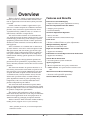
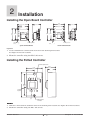
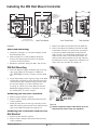
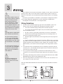
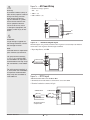
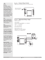
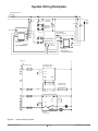
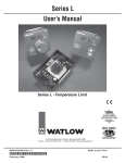
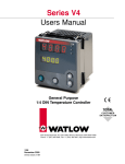
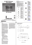
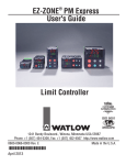
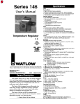
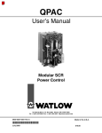
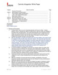
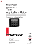
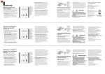
Series L
User’s Manual
Series L - Temperature Limit
TOTAL
TOTA
S
3Y
Year
ear Warranty
arranty
ISO 9001
Registered Company
1241 Bundy Boulevard., Winona, Minnesota USA 55987
Phone: +1 (507) 454-5300, Fax: +1 (507) 452-4507 http://www.watlow.com
0600-0044-0001 Rev. F
November 2006
Winona, Minnesota USA
Made in the U.S.A.
$5.00
Safety Information
We use note, caution and warning symbols throughout this book to draw your attention to
important operational and safety information.
A “NOTE” marks a short message to alert you to an important detail.
ç
CAUTION or
WARNING
Ó
Electrical
Shock Hazard
CAUTION or WARNING
A “CAUTION” safety alert appears with information that is important for protecting your
equipment and performance. Be especially careful to read and follow all cautions that apply to
your application.
A “WARNING” safety alert appears with information that is important for protecting you, others and equipment from damage. Pay very close attention to all warnings that apply to your
application.
The safety alert symbol, ç (an exclamation point in a triangle) precedes a general CAUTION
or WARNING statement.
The electrical hazard symbol, Ó (a lightning bolt in a triangle) precedes an electric shock hazard CAUTION or WARNING safety statement.
Technical Assistance
If you encounter a problem with your Watlow controller, review your configuration information to verify that your selections are consistent with your application: inputs, outputs, alarms,
limits, etc. If the problem persists, you can get technical assistance from your local Watlow representative (see back cover), by e-mailing your questions to [email protected] or by
dialing +1 (507) 494-5656 between 7 a.m. and 5 p.m., Central Standard Time (CST). Ask for for
an Applications Engineer. Please have the following information available when calling:
• Complete model number
• System wiring information
• Series L Limit User’s Manual
Warranty
These controllers are manufactured by ISO 9001-registered processes and are backed by a
three-year warranty.
Return Material Authorization (RMA)
1. Call Watlow Customer Service, (507) 454-5300, for a Return Material Authorization (RMA)
number before returning any item for repair. We need this information:
•
Ship to address
•
Bill to address
•
Contact name
•
Phone number
•
Method of return shipment
•
Your P.O. number
•
Detailed description of the problem
•
Any special instructions
•
Name and phone number of person returning the product.
2. Prior approval and an RMA number, from the Customer Service Department, is needed
when returning any unused product for credit. Make sure the RMA number is on the outside of
the carton, and on all paperwork returned. Ship on a Freight Prepaid basis.
3.
After we receive your return, we will examine it and try to verify the reason for the return.
4. In cases of manufacturing defect, we will enter a repair order, replacement order or issue
credit for material returned.
5. To return products that are not defective, goods must be be in new condition, in the original boxes and they must be returned within 120 days of receipt. A 20 percent restocking charge
is applied for all returned stock controls and accessories.
6.
If the unit is unrepairable, it will be returned to you with a letter of explanation.
7.
Watlow reserves the right to charge for no trouble found (NTF) returns.
The Series L Limit user’s manual is copyrighted by Watlow Winona, Inc., © November 2006
with all rights reserved.
1
Overview
Watlow's Series L family of temperature limit controllers* provide an economical limit controller solution for applications where thermal system protection
is needed.
A limit controller is added to applications to prevent over or under temperature conditions. The limit
provides safety assurances against instances where
a thermal runaway condition occurs as a result of a
failed sensor, controller or output device.
The Series L limit controller is recommended for
any application where thermal system runaway could
result in large product scrap costs, damage to system
equipment, potential fire hazard or risk to personnel.
All Series L limit controllers are Factory Mutual and
CSA approved.
These controllers are available with or without an
operator interface and can be ordered in square 1/8th
DIN panel mount, din rail mount, open board or potted module design configurations. Push-on, quick connect spade terminal or removable screw clamp style
terminal block ordering options provide the electrical
connections.
The microprocessor design platform provides improvements in the performance, repeatability, and accuracy offered by Watlow's current line of basic control
products.
The Series LV includes an operator interface to allow viewing and selection of the limit set point. A red
four character, seven-segment LED displays the limit
set point. The limit set point selection is made with
a continuous turn, velocity-sensitive rotary encoder.
Push-to-Set operation reduces accidental limit set
point adjustments. Limit set point operating range
temperature values are customer definable in the
product configuration part number.
The Series LF offers fixed limit set points. These
units are supplied without an operator interface. Limit
set point temperature values are customer definable in
the product configuration part number.
The features and performance of these products
make them ideally suited for a wide range of industrial
limit control applications in the food preparation, industrial machinery, packaging and plastic markets.
Watlow's Series L limit controllers include industryleading service, support and a 3-year warranty.
Features and Benefits
Four-Character LED Display
• Improves limit set point adjustment accuracy.
Fixed or Adjustable Limit Set Points
• Tamper proof operation.
• Control flexibility.
Set Point Adjustment Opetions
• Rotary encoder.
• Tactile increment and decrement keys.
Push to Set
• Reduce accidental limit set point adjustments.
Multiple Mounting Options
• Minimizes installation time.
High or Low Limit Operation
• Application flexibility.
Fahrenheit or Celsius Operation with Indication
• Application flexibility.
Sensor Break Protection
• Provides positive system shutdown.
Agency Approvals
• Meets requirements for agency certification.
• NEMA 4X/IP65 seal panel mount versions available.
Micro Processor Based Technology
• Accurate and repeatable protection.
Stock to Four-Day Delivery
*Also available, Series C, an on-off temperature
controller version.
Watlow Series L
• 1 •
Chapter 1: Overview
2
Installation
Installing the Open Board Controller
61.7 mm
(2.43 in)
61.7 mm
(2.43 in)
45.07 mm
(1.775 in)
56.3 mm
(2.22 in)
61.7 mm
(2.43 in)
45.07 mm
(1.775 in)
56.3 mm
(2.22 in)
SWDC+ .6
N.O.
55.9 mm
(2.20 in)
61.7 mm
(2.43 in)
SWDC- .7
COM
55.9 mm
(2.20 in)
N.C. .8
L2 .9
L1
.10
Terminal Designation Sticker
Use M2.5 (#4) mounting
hardware,
e, not included
Terminal Designation Sticker
Use M2.5 (#4) mounting
hardware,
e, not included
Screw Terminal Model
Spade Terminal Model
Figure 2a
1. Locate and drill four 3.2 mm (0.125 in) holes in the desired panel location.
See Figure 2a for hole locations.
2. Mount the controller using four M2.5 (#4) screws.
Installing the Potted Controller
Terminal Designation Sticker
46.6 mm
(1.84 in)
70.1 mm
(2.76 in)
35.1 mm
(1.38 in)
35.1 mm
(1.38 in)
102.9 mm
(4.05 in)
88.9 mm
(3.50 in)
Terminal
Designation
Sticker
Terminal Designation Sticker
Use [3.5M] #6 hardware,
not included
Figure 2b
1. Drill two 5 mm (0.187 in) diameter holes in the desired panel location. See Figure 2b for hole locations.
2. Mount the controller using two M3.5 (#6) screws.
Watlow Series L
• 2 •
Chapter 2: Installation
Installing the DIN Rail Mount Controller
94.7 mm
(3.73 in)
78.1 mm
(3.08 in)
90.7 mm
(3.57 in)
39.1 mm
(1.54 in)
81.8 mm
(3.22 in)
To install or remove,
press down here.
See Installing/ Removing
the DIN Rail Controller
procedures below.
Part Number Label
80.0 mm
(3.07 in)
DIN rail, upper
mounting clip
101.6 mm
(4.00 in)
80.3 mm
112.3 mm
(3.16 in)
(4.42 in)
1. SW-1
2. SW-2
35 mm x 7.5 mm
DIN rail is not included
with the assembly
3.TC-/S1
4.TC+/S2
5.
S3
Terminal Designation Sticker
Agency Label
Panel mounting the bracket requires
two M3.5 (#6) screws, not included
To install, press in here.
To remove, pull out here.
See Mounting/Removing the
DIN Rail Controller procedures below.
Spade Terminal Model
Screw Terminal Model
Tactile Key Model
Figure 3a
3. Remove the DIN rail bracket from the DIN rail.
Sub-Panel Mounting
4. Insert a flat blade screwdriver between the DIN
rail bracket and the case. Rotate the screwdriver
to release the DIN rail bracket hooks from the
ridges on the case, while firmly pushing the controller out the front of the DIN rail bracket. Alternate back and forth between the top and then
the bottom. Be sure to support the controller as it
comes out of the bracket. See Figure 3b.
1. Using the controller as a location template, mark
both mounting holes.
2. Drill and tap two 2.7 mm (0.106 in) diameter
holes in the desired panel location. See Figure
3a above for hole locations.
3. Mount the controller using two M3.5 (#6) screws.
DIN Rail Mounting
1. Place the DIN rail upper mounting clip on the top
edge of the DIN rail. See Figure 3a. DIN rail
spec, DIN 50022, 35 mm x 7.5 mm (1.38 in x 0.30
in).
2. Press down firmly on the top back edge of the DIN
rail bracket and push in on the bottom, front edge
of the bracket. The controller snaps securely onto
the rail. See Figure 3a. If the controller does
not snap on, check to see if the DIN rail is bent.
Minimum clipping distance is 34.8 mm (1.37 in),
the maximum is 35.3 mm (1.39 in).
Press forward
with thumb.
Removing the DIN Rail Controller
1. Remove power from the system.
Insert flat blade screwdriver here.
2. Remove all the wiring connections from the back
of the controller.
3. While pressing down on the top, back edge of the
DIN rail bracket, pull forward on the bottom, front
edge of the DIN rail bracket. See Figure 3a.
Figure 3b
ç Caution: FM approval requires limit switches to be suitably enclosed to restrict casual user adjustment.
Removing the Controller from the DIN
Rail Bracket
1. Remove power from the system.
2. Remove all the wiring connections from the back
of the controller.
Watlow Series L
• 3 •
Chapter 2: Installation
72.4 mm
(2.85 in)
68.0 mm
(2.68 in)
Panel Cutout
Panel Thickness
1.52 to 3.18 mm
(0.060 to 0.125 in)
72.4 mm
(2.85 in)
in
68.0 mm
(2.68 in)
19.1 mm
(0.75 in)
minimum
19.1 mm
(0.75 in)
minimum
Spade Terminal Model
Customer Front Panel
Part Number Label
84.5 mm square
(3.33 in)
Terminal Blocks Locations
on Screw Terminal Models
Mounting Bracket
6.4 mm
(0.25 in)
Tactile Key,
Screw Terminal Model
19.2 mm
(0.76 in)
51.7 mm
(2.04 in)
Spade Terminal Model
installation. See Figure 4. Slide the collar firmly
against the back of the panel, getting it as tight
as possible. To ensure a tight seal, use your thumb
to lock the tabs into place while pressing the case
from side to side. Don’t be afraid to apply enough
pressure to install the controller. The tabs on
each side of the collar have teeth that latch into
the ridges. Each tooth is staggered at a different
height, so only one of the tabs on each side are
ever locked into the ridges at a time. Confirm that
the tabs on one side of the collar correspond with
those on the opposite side. Make sure the two corresponding tabs are the only ones locked in the
ridges at the same time. If the corresponding tabs
are not supporting the case at the same time, you
will not have a NEMA 4X seal.
Figure 4
Installing the Square 1/8 DIN Panel
Mount Controller
1. Make the panel cutout using the mounting dimensions above.
2. Remove mounting bracket from the back of the
controller.
3. If your controller has a gasket, check to see that
the gasket is not twisted, and is seated within the
case bezel flush with the panel. Place the case in
the cutout. Make sure the gasket is between the
panel cutout and the case bezel.
4. While pressing the front of the case firmly against
the panel, slide the mounting collar over the back
of the control. The tabs on the collar must line up
with the mounting ridges on the case for secure
Watlow Series L
Screw Terminal Models
Contact your local Greenlee supplier for the appropriate
punch kit and cutout tool for rapid mounting.
5. Insert the control chassis into its case and press
the bezel to seat it. Make sure the inside gasket
• 4 •
Chapter 2: Installation
is also seated properly and not twisted. The hardware installation is complete. Proceed to the wiring section.
2. Insert the controller into the panel cutout.
3. While pressing the bezel firmly against the panel,
slide the mounting bracket over the back of the
controller. Be sure the levers on the mounting
bracket line up with the teeth on the case.
4. Press the bracket up to the back of the panel. The
controller should fit tightly in the panel cutout.
Removing the Panel Mount Square
1/8 DIN Controller
1. Remove power from the system.
2. Remove all the wiring connections from the back
of the controller.
3. Slide a thin, wide tool (putty knife) under all three
mounting tabs, top then bottom, while pushing forward on the back of the case. Be ready to support
the controller as it slides out of the panel cutout.
çCaution: FM approval requires limit switches to be
suitably enclosed to restrict casual user adjustment.
Watlow Series L
• 5 •
Chapter 2: Installation
3
Wiring
Ó
Warning:
Use National Electric (NEC) or
other country-specific standard
wiring and safety practices
when wiring and connecting this controller to a power
source and to electrical sensors or peripheral devices. Failure to do so may result in damage to equipment and property,
and/or injury or loss of life.
Note:
Insulated terminals required for
quick connect style terminals.
For quick connect terminals
1, 2, 6, 7, 8, 9, and 10, AMP
P/N 3-520406-2 or equivalent
recommended. Use Amp crimp
tool P/N 58078-3, insert 903913.
For quick connect terminals 3,
4, and 5, AMP P/N 2-520405-2
or equivalent recommended.
Amp crimp tool P/N 58078-3,
insert 58079-3.
ç
Caution:
FM approval requires limit
switches to be suitably enclosed to restrict casual user
adjustment.
The terminals on the back of the Series L limits are the same for all of the
package styles. They are 6.3 mm (0.25 in) quick connect, push on style terminals or removable screw terminal block. The terminal style is an ordering
option.
Check the part number to determine your hardware configuration. Refer
to the wiring diagrams appropriate for your controller’s configuration.
All outputs are referenced to a de-energized state.
Wiring Guidelines
1. Use the correct thermocouple type per the model number on the case
sticker of the unit. See dimension drawings for sticker locations.
•
Use correct thermocouple polarity. Red is usually negative.
• If you must extend thermocouple leads, use thermocouple extension
wire to minimize errors.
•
Be sure you have good crimp connections on all wire connections.
• Insulate the thermocouple mounting from the mounting surface to
prevent heat migration input errors.
• Thermocouple leads should be routed separately from any high voltage lines.
• Long lead lengths create electrical resistance. When using a two-wire
RTD, there will be an additional 2.6° C (4.7° F) error for every 1Ω of lead
length resistance. That resistance when added to the resistance of the
RTD element, can result in erroneous input to the temperature controller.
2. In electrically-noisy environments (heavy switching contactors, motors,
solenoids, etc.), use shielded thermocouple lead wire with the shield connected at the sensor end only.
3. Use a separate thermocouple to maintain the limit function of this
controller; do not parallel thermocouple input from the primary controller.
4. All wiring and fusing must conform to the National Electric Code (NEC)
NFPA70 and any other locally applicable codes.
5. Fuse the independent load voltage on the L1 (hot) side and connect it to
the common (C) side of the relay.
Note: The model number determines the connection terminal style. See below for terminal
locations.
1
2
3
4
5
Watlow Series L
6
7
8
9
10
• 6 •
1
2
3
4
5
Chapter 3: Wiring
ç
Warning:
Use National Electric (NEC) or
other country-specific standard
wiring and safety practices
when wiring and connecting this controller to a power
source and to electrical sensors or peripheral devices.
Failure to do so may result
in damage to equipment and
property, and/or injury or loss
of life.
Figure 7a — AC Power Wiring
• Nominal voltage options:
• 24VÅ (ac)
• 120VÅ (ac)
• 230 to 240VÅ (ac)
1
2
3
4
5
L2
L1
Ó
WARNING:
If high voltage is applied to a
low-voltage controller, irreversible damage will occur.
Figure 7b — Thermocouple Input
Thermocouples are polarity sensitive. The negative lead (usually red) must be
connected to the negative thermocouple terminal.
Note:
Insulated terminals required for
quick connect style terminals.
• Input impedance: >10 MΩ
For quick connect terminals
1, 2, 6, 7, 8, 9, and 10, AMP
P/N 3-520406-2 or equivalent
recommended. Use Amp crimp
tool P/N 58078-3, insert 903913.
1
2
For quick connect terminals 3,
4, and 5, AMP P/N 2-520405-2
or equivalent recommended.
Amp crimp tool P/N 58078-3,
insert 58079-3.
Thermocouple
Thermocouple
3
4
5
Figure 7c — RTD Input
(100 Ω Platinum DIN curve 0.00385 Ω/
Ω/Ω
/Ω/°C)
Ω/°C)
• Terminals S2 and S3 must be shorted for a two-wire RTD
• Nominal excitation current: 125 µA
3-Wire RTD*
2-Wire RTD
RTD S1
RTD S1
RTD S2
RTD S3
RTD S2
S3
1
*No lead resistance
compensation
Watlow Series L
• 7 •
Chapter 3: Wiring
ç
Warning:
Use National Electric
(NEC) or other countryspecific standard wiring
and safety practices when
wiring and connecting
this controller to a power
source and to electrical
sensors or peripheral devices. Failure to do so may
result in damage to equipment and property, and/or
injury or loss of life.
Note:
Use of an external reset
switch may affect FM approval. Only the use of a
momentary N.O. switch is
valid for approval.
Figure 8a — External Reset Switch
• Momentary normally open (N.O.), dry contact closure
Momentary N.O. Switch
(customer supplied)
SW-1
SW-2
1
2
3
4
5
Figure 8b — Mechanical Relay Output
• Form C contacts
• 8 A, resistive
• 250 VA pilot duty, 120/240VÅ (ac), inductive
Note:
Insulated terminals required for quick connect
style terminals.
• 240VÅ (ac) maximum
For quick connect terminals 1, 2, 6, 7, 8, 9, and
10, AMP P/N 3-520406-2
or equivalent recommended. Use Amp crimp tool P/
N 58078-3, insert 90391-3.
• Minimum load current 100 mA
For quick connect terminals 3, 4, and 5, AMP P/N
2-520405-2 or equivalent
recommended. Amp crimp
tool P/N 58078-3, insert
58079-3.
Quencharc Note:
Switching pilot duty loads
(relay coils, solenoids, etc.)
with the mechanical relay
output option requires use
of an R.C. suppressor.
• 30VÎ (dc) maximum
• See Quencharc note
• For use with ac or dc
• Output does not supply power
Customer supplied Quencharc
for pilot duty, inductive loads
only. See note.
External
Load
1
2
N.O. Normally Open
Common
Normally Closed
3
4
5
L2
L1
Mechanical Relay
10
N.O.
COM.
N.C.
Internal Circuitry
Watlow carries the R.C.
suppressor Quencharc
brand name, which is a
trademark of ITW Paktron.
Watlow Part No. 08040147-0000.
Watlow Series L
• 8 •
Chapter 3: Wiring
System Wiring Examples
Power Disconnect
Switch
L1
120V~(ac)
L2
Fuse
Customer
Supplied
Quencharc
Fuse
Not used
1
2
Fuse
High Limit
Mechanical
Contactor
coil
Fuse
6 SWDC+
SWDC7
8
L2
9
TC- 3
TC+ 4
5
10
Reset Switch
(customer supplied)
SW-1
SW-2
L1
+
SSR-240-10A-DC1
in out
Solid-State Relay
-
Series CV
Temperature Controller
Controlle
CVB1JH00000100C
1
2
TC-
N.O.
COM
7
N.C.
8
L2
9
6
3
TC+
4
5
L1
10
Heater
Series LF
Limit Control
LFC4JW0120AAAAA
Limit Sensor
Process Sensor
120VÅ (ac)
L1
L2
Series CV
Temperature Controller
CVB1JH00000100C
Power Disconnect
Switch
1
1
HighTemp.
Light
3
2
4 (+)
3
5 (-)
10
L1
4
TC+
3
TC-
L2 9
SWDC+
6
4
2
SWDC7
6
7
3 to 32
VÎ (dc) in
(+)
SSR-240-10A-DC1
Solid-State Relay
(-)
1 CR-1
5
6
1
1
8
48 to 260
VÅ out
9
10
11
L1
9
14 (+)
10
15 (-)
11
12
13
1
4
2
L2 9
7
8
Heater
10
TC+
SW-1
1
SW-2
2
N.O.
6
N.C.
8
3 TC7 COM
17
13
16
18
Series LF
Limit Controller
LFC4JW0120AAAAA
2
12
1 CR
R
2
2
High-Temperature Light
High-T
Figure 9 — System Wiring Examples
Watlow Series L
• 9 •
Chapter 3: Wiring
4
User Interface
LV _ (1, 2, 5 or 6) _ _ _ _ _ _ _ _ _ _ A
LIMIT LV
LED Display: Indicates
the limit set point.
SET/RESET Key: Press
and hold key to adjust the
limit set point temperature.
New limit set point is
entered 3 seconds after
the knob stops moving.
Press key to reset latched
limit output once
tempera-ture is back in
safe region. Can also be
reset through customer
supplied external reset
switch.
F
C
ALARM
°F or °C Indicator Light: Lit to
indicate if unit is configured for
degrees Fahrenheit or degrees
Celsius.
ALARM Indicator Light: Lit
when limit is tripped.
Finger Tip Indent: Insert
finger tip into indent for quick
and easy set point changes.
SET
Limit Set Point Knob: To
increase limit set point, turn
knob clockwise. To decrease
limit set point, turn knob
counter-clockwise. The new set
point is entered 3 seconds after
the knob stops moving. Limit
set point will not change unless
SET/RESET key is pressed.
RESET
Figure 10 — Variable Limit Set Point, Standard Interface
LV _ (A, B, C or D) _ _ _ _ _ _ _ _ _ _ A
LIMIT LV
F
C
LED Display: Indicates
the limit set point.
SET/RESET Key: Press
and hold key to adjust the
limit set point temperature.
New limit set point is
entered 3 seconds after
the last key press.
Press key to reset latched
limit output once
temperature is back in
safe region. Can also be
reset through customer
supplied external reset
switch.
ALARM
°F or °C Indicator Light: Lit to
indicate if unit is configured for
degrees Fahrenheit or degrees
Celsius.
ALARM Indicator Light: Lit
when limit is tripped.
Increment and Decrement
Keys: Press the Up-Arrow key
to increase the limit set point.
Press the Down-Arrow key to
decrease the limit set point.
The new set point is entered 3
seconds after the last key
press.
The limit set point will not
change unless the SET/RESET
key is presses.
SET
RESET
çCaution: FM approval requires limit switches to be suitably enclosed to restrict casual user adjustment.
To adjust the Calibration Offset on models with tactile
keys, first hold down both the Increment and Decrement keys for five seconds. The display will first show
[`CAL] for five seconds, then it will display the Calibration Offset value. Adjust the value with the Increment and Decrement keys (range: -30 to 30°). The new
value will take effect three seconds after the last key
stroke. The display will blink, then return to the primary display after five seconds.
Watlow Series L
To change the temperature units on models with
tactile keys, first hold down both the Increment and
Decrement keys for ten seconds. The display will show
[F``C] for two seconds. Adjust the units with the Increment and Decrement keys. The new value will take
effect three seconds after the last key stroke. The display will blink, then return to the primary display after
five seconds. The set point value, process value and
offset will automatically adjust to the new temperature
scale.
• 10 •
Chapter 4: User Interface
Troubleshooting
Indication
Probable Cause(s)
Corrective Action
On indicating limits, the display is not illuminated.
• Power supply switch off.
• Fuse blown.
• Breaker tripped.
• Safety interlock door switch activated.
• Wiring incorrect or open.
• Power supply voltage incorrect.
• Defective limit.
• Turn switch on.
• Replace fuse (check cause of failure).
• Reset breaker (check cause of failure).
• Close door.
• Check wiring.
• Verify input power
• Repair or replace limit.
Temperature reading is incorrect, showing a sensor error,
[Er;In] , or ALARM LED is
switching at the wrong temperature.
• Setting for degree C or F is incorrect. • Check the model part number for
Degree C or F. If the model has Increment/Decrement keys, then the C/F
setting is adjustable.
Troubleshooting thermocouple inputs
• Sensor or limit may be bad. Sensor
connections may be bad.
• Place a jumper wire across the thermocouple input terminals. The display
should indicate ambient temperature.
If it does, the limit is OK.
- For high limit: Start with limit set
point above ambient temperature,
ALARM LED should be off. Decrease
limit set point until ALARM LED goes
on. It should be approximately ambient temperature.
- For low limit: Start with limit set point
below ambient temperature, ALARM
LED should be off. Increase limit set
point until ALARM LED goes on. It
should be approximately ambient temperature.
• Ambient temperature in the control
cabinet is over 70°C.
• Measure temperature in cabinet to
ensure it is below 70C. Vent cabinet or
add fans if necessary.
• Ground loop problem. Can occur when
using a switched DC output and a
grounded thermocouple.
• Remove power from the system. Use
an ohm meter to measure resistance
between output DC- and the thermocouple sheath. If there is continuity,
replace sensor with an ungrounded
thermocouple.
Temperature seems to be decreasing, but actual process is
increasing.
• Thermocouple polarity is reversed. In
the US, red wire insulation denotes
the negative wire.
• Check thermocouple connections. All
connections, including extension wire
must maintain the correct polarity.
Correct polarity problems.
Temperature seems to be reading low and not increasing
while actual process temperature is increasing.
• Sensor is bad. Thermocouple is shorted. • Check thermocouple connections.
Check thermocouple wire insulation
to make sure it is not damaged, causing the wires to short (making a new
junction).
Temperature seems to be offset from actual process temperature, or the ALARM LED
switches on at the wrong temperature. The offset changes
with changes in process temperature.
• Copper wire was used instead of thermocouple extension wire. Connectors
of metals different than thermocouple
metal were used to splice or make
connections.
Watlow Series L
• 11 •
• Check thermocouple connections.
Check to make sure that only thermocouple extension wire of the correct
type was used to extend thermocouple
leads. Replace if necessary.
Chapter 5: Troubleshooting
Indication
Probable Cause(s)
Corrective Action
Troubleshooting RTD inputs
Temperature reading is incorrect,
showing a sensor error, [Er;In] , or
ALARM LED is switching at the
wrong temperature.
• Setting for degree C or F is incorrect.
Check model part number for Degree C or F. If the model has Increment/Decrement keys, then the C/F
setting is adjustable.
• Sensor or limit may be bad. Sensor
connections may be bad.
• Place a 110 ohm resistor across the
sensor input terminals.
- For high limit: Start with limit set
point above ambient temperature,
ALARM LED should be off. Decrease limit set point until ALARM
LED goes on. It should be approximately ambient temperature. If it
does, the limit is OK. Sensor or connections may be bad.
- For low limit: Start with limit set
point below ambient temperature,
ALARM LED should be off. Increase limit set point until ALARM
LED goes on. It should be approximately ambient temperature. If it
does, the limit is OK. Sensor or connections may be bad.
• Ambient temperature in the control
cabinet is over 70°C (158°F).
• Measure temperature in cabinet to
ensure it is below 70°C (158°F). Vent
cabinet or add fans if necessary.
• Sensor connections may be bad. Excessive lead wire resistance.
• Check sensor connections. Measure
lead wire resistance. There will be a
2.6C (4.7°F) error for every ohm of
lead wire resistance.
Troubleshooting limit outputs
ALARM is not tripped when it
should be. ALARM LED is not on
(relay is energized in safe condition,
N.O. contact is closed and N.C. contact is open).
• Temperature appears to be incorrect. See input troubleshooting.
• See input troubleshooting.
• Limit set point is not set correctly.
• Verify limit set point setting.
ALARM is tripped when it should
not be. ALARM LED is on (relay is
de-energized in limit condition, N.O.
contact is open and N.C. contact is
closed).
• Limit output is tripped (latched).
• Press RESET key to reset limit.
• Output wiring is incorrect.
• Verify wiring. Relay outputs act as
a switch, they do not source power.
• Temperature appears to be incorrect, see input troubleshooting.
• See input troubleshooting.
• Limit set point is not set correctly.
• Verify limit set point setting.
• Limit output is defective.
• Repair or replace limit.
• Temperature reading is incorrect
on display of indicating controls or
limit, see input troubleshooting.
• See input troubleshooting.
• Set point is not set correctly.
• Verify limit set point setting.
• Power switching device (mechanical relay, contactor, etc.) is shorted.
Limit output shorted.
• Remove wires from output of limit
to input of power switching device.
If load is still on, replace power
switching device. If load turns off,
replace limit or sensor. See input
troubleshooting.
• Output wiring is incorrect.
• Verify wiring.
Limit output signal is on when it
should not be on. Load LED is on.
Limit load is on when it should be
off. ALARM LED is off.
Watlow Series L
• 12 •
Chapter 5: Troubleshooting
Specifications
Controller
• Microprocessor based, limit controller.
• Nominal switching hysteresis, typically 1.7°C (3°F)
• High or low limit, factory selectable.
• Latching output requires manual reset upon over
or under temperature condition.
• Manual or automatic reset on power loss, factory
selectable.
• Internal front panel or external customer supplied
momentary reset switch.
• Input filter time: 1 second.
Operator Interface (model dependent)
• Four digit , 7 segment LED displays, .28" high.
• °F or °C indicator LED.
• ALARM indicator LED.
• Continuous turn, velocity sensitive rotary encoder
for limit set point adjustment.
• Front panel SET/RESET key on variable set point
models.
• No operator interface on fixed set point models.
Standard Conditions For Specifications
• Rated line voltage, 50 to 60Hz, 0 to 90% RH noncondensing, 15-minute warm-up.
Calibration ambient range: 25°C (77°F) ±3°C
Sensor Input
Thermocouple
• Grounded or ungrounded.
• Type E, J, K, T thermocouple types.
• >10 MΩ input impedance.
• 250 nV input referenced error per 1 Ω source resistance.
RTD
• 2-wire platinum, 100 Ω.
• DIN curve (.00385 curve).
• 125 µA nominal RTD excitation current.
Input Accuracy Span Range
Thermocouple Input
Type E
-200 to 800°C or -328 to 1,470°F
Type J:
0 to 750°C or
32 to 1,382°F
Type K:
-200 to 1,250°C or -328 to 2,282°F
Type T:
-200 to 350°C or -328 to 662°F
RTD (DIN): -200 to 800°C or -328 to 1,472°F
• Calibration accuracy: ±1% of input accuracy span,
±1° at standard conditions and actual calibration
ambient.
Exception: Type T, ±2.4% of input accuracy span
for -200 to 0°C (-328 to 32°F)
• Temperature stability: ±0.3 degree per degree
change in ambient.
Watlow Series L
RTD Input
• Calibration accuracy: ±1% of input accuracy span
±1° at standard conditions and actual calibration
ambient.
• Temperature stability: ±0.2 degree per degree
change in ambient
Allowable Operating Ranges
Type E
-200 to 800°C or -328 to 1,470°F
Type J:
-210 to 1,038°C or -346 to 1,900°F
Type K:
-270 to 1,370°C or -454 to 2,500°F
Type T:
-270 to 400°C or -454 to 750°F
RTD (DIN): -200 to 800°C or -328 to 1,472°F
External Reset Switch
• Momentary, dry contact closure. See wiring section.
Output Types
Electromechanical Relay, Form C
• Minimum load current: 100 mA.
• 8 A @ 240VÅ (ac) or 30VÎ (dc) maximum, resistive.
• 250 VA pilot duty, 120/240VÅ (ac) maximum, inductive.
• Use RC suppression for inductive loads.
• Electrical life 100,000 cycles at rated current.
Agency Approvals
Series LF (potted version only)
• UL 991 recognized temperature limit for food service industry.
Series LV and Series LF (including potted version)
• UL 873 recognized temperature regulator. File
#E43684.
• UL 197 reviewed for use in food service appliances.
• ANSI Z21.23 Gas appliance thermostat approval.
• CSA C22.2#24 approved temperature control. File
#30586.
• FM Class 3545 temperature limit switches. File
#3017239.
• NEMA 4X/IP65 on panel-mount versions with tactile keys for set point adjustment.
• CE - see Declaration of Conformity.
Terminals
• 6.4 mm (0.25 in) quick connect, push-on terminals. See order options. Refer to Wiring section for
crimp-on terminal recommendations.
• Removable screw clamp style terminal blocks. See
order options.
• Wire gauge 0.1 to 4 mm2 (30 to 12 AWG). Strip
length, 8 mm (0.30 in).
• Torque: 0.8 Nm (7 in-lb) maximum.
• 13 •
Appendix
Power
• 24VÅ (ac) +10%; -15%; 50/60 Hz, ±5%
• 120VÅ (ac) +10%; -15%; 50/60 Hz, ±5%
• 208 to 240VÅ (ac) +/-10%, Series LF and CF only
• 230 to 240VÅ (ac) +10%; -15%; 50/60 Hz, ±5%
• 10VA maximum power consumption.
• Data retention upon power failure via nonvolatile
memory.
Operating Environment
• 0 to 70°C (32 to 158°F)
• 0 to 90% RH, non-condensing.
• Storage temperature: -40 to 85°C (-40 to 185°F)
Dimensions
• DIN Rail model can be DIN rail or chassis mount
DIN rail spec, DIN 50022, 35 mm x 7.5 mm (1.38
in x 0.30 in)
Style
Width
Height
Depth
Open board
61.7 mm
(2.43 in)
61.7 mm
(2.43 in)
45.1 mm
(1.78 in)
Potted
70.1 mm
(2.76 in)
102.9 mm
(4.05 in)
46.6 mm
(1.84 in)
DIN Rail
78.1 mm
(3.08 in)
112.3 mm
(4.42 in)
90.7 mm*
(3.57 in)
Square
1/8DIN
Panel
72.4 mm
(2.85 in)
72.4 mm
(2.85 in)
Behind panel
51.7 mm
(2.04 in)
*Depth including DIN rail, 94.7 mm (3.73 in)
Note: These specifications are subject to change without
prior notice.
Watlow Series L
Glossary
automatic power reset — A feature in latching limit
controllers that does not recognize power outage as a
limit condition. When power is restored, the output is
re-energized automatically, as long as the temperature
is within limits.
latched output — Limit control output latches in deenergized condition when over or under temperature
condition occurs and cannot be reset unless temperature drops below set point.
limit or limit controller — A highly reliable, discrete
safety device (redundant to the primary controller) that
monitors and limits the temperature of the process or a
point in the process. When temperature exceeds or falls
below the limit set point, the limit controller interrupts
power through the load circuit. A limit controller can
protect equipment and people when it is correctly installed with its own power supply, power lines, switch
and sensor.
manual power reset — A feature in latching limit
controllers that does recognize power outage as a limit
condition. When power is restored, the output is not reenergized automatically, even if the process is within
limits. An operator must use the reset key or switch to
manually re-energize the output on power up.
manual reset — A feature on a limit controller that
requires human intervention to return the limit to normal operation after a limit condition has occurred.
safety limit — An automatic limit intended for use
in applications where an over-temperature fault may
cause a fire.
• 14 •
Appendix
Ordering Information and Model Numbers
Limit Control no user interface
L F
_ _ _ _
_ _ _ _
A A A A
_
Set Point Type
F
Fixed Limit Set Point
Line Voltage
C
120VÅ (ac)
E
230 to 240VÅ (ac)
G
24VÅ (ac)
Controller Package
1
Panel Mount, Square 1/8 DIN, Spade Terminals
2
DIN Rail Mount, Spade Terminals
3
Open Board, not potted, Spade Terminals
4
Potted Case, Spade Terminals
5
Panel Mount, Square 1/8 DIN, Screw Terminals
6
DIN Rail Mount, Screw Terminals
7
Open Board, not potted, Screw Terminals
Sensor and Sensor Operating Range
H
Type J -346 to 1,900°F
J
Type J -210 to 1,038°C
K
Type K -454 to 2,500°F
L
Type K -270 to 1,370°C
M
Type T -454 to 750°F
N
Type T -270 to 400°C
P
100 Ω RTD -328 to 1,472°F
R
100 Ω RTD -200 to 800°C
S
Type E -328 to 1,470°F
T
Type E -200 to 800°C
Limit Type
U
High Limit, External manual reset on power up, external manual reset on
over temperature
W
High Limit, Auto reset on power up, external manual reset on over temperature
Y
Low Limit, External manual reset on power up, external manual reset on
under temperature
Z
Low Limit, Auto reset on power up, external manual reset on under temperature
Fixed Limit Set Point Value *
XXXX
Limit Set Point Value**
Overlay/Custom Option
A
Standard
*Note: Limit set point must fall within the sensor operating range.
**Note: A (-) is used in the left digit of the operating range to indicate negative values.
Watlow Series L
• 15 •
Appendix
Ordering Information and Model Numbers
Limit Control, LED display,
front panel reset switch
L V
_ _ _ _
_ _ _ _
_ _ _ _
_
Set Point Type
V
Variable Limit Set Point
Line Voltage
C
120VÅ (ac)
E
230 to 240VÅ (ac)
G
24VÅ (ac)
Controller Package
1
Panel Mount, Square 1/8 DIN, Rotary Knob, Spade Terminals
2
DIN Rail Mount, Rotary Knob, Spade Terminals
5
Panel Mount, Square 1/8 DIN, Rotary Knob, Screw Terminals
6
DIN Rail Mount, Rotary Knob, Screw Terminals
A
NEMA 4X/IP65, Panel Mount, Tactile Keys, Spade Terms
B
DIN-rail Mount, Tactile Keys, Spade Terminals
C
NEMA 4X/IP65, Panel Mount, Tactile Keys, Screw Terms
D
DIN-rail mount, Tactile Keys, Screw Terminals
Sensor and Sensor Operating Range
H
Type J -346 to 1,900°F
J
Type J -210 to 1,038°C
K
Type K -454 to 2,500°F
L
Type K -270 to 1,370°C
M
Type T -454 to 750°F
N
Type T -270 to 400°C
P
100 Ω RTD -328 to 1,472°F
R
100 Ω RTD -200 to 800°C
S
Type E -328 to 1,470°F
T
Type E -200 to 800°C
Limit Type
U
High Limit, Manual Reset on power up, manual reset on over temperature
W
High Limit, Auto Reset on power up, manual reset on over temperature
Y
Low Limit, Manual Reset on power up, manual reset on under temperature
Z
Low Limit, Auto Reset on power up, manual reset on under temperature
Low Limit Set Point Range Limit*
XXXX
Low Limit Set Point Operating Range Value**
High Limit Set Point Range Limit*
XXXX
High Limit Set Point Operating Range Value
Overlay/Custom Option
A
Standard
*Note: Set point ranges must fall within the sensor operating range.
**Note: A (-) is used in the left digit of the operating range to indicate negative values.
Watlow Series L
• 16 •
Appendix
Declaration of Conformity
Series L
Watlow Winona, Inc.
1241 Bundy Blvd.
Winona, MN 55987 USA
Declares that the following product:
Designation:
Series L
Model Numbers:
LF - (C, E or G) (1, 2, 3, 4, 5, 6 or 7) (any letter) (U, W, Y or Z) (any four numbers or - and three numbers) - (AAAA) - may be followed by additional numbers or letters
LV - (C, E or G) (1, 2, 5 or 6) (any letter) (U, W, Y or Z) - (any four numbers or
- and three numbers) - (any four numbers) - may be followed by additional numbers or letters
Classification:
LF and LV = Temperature Regulator Installation Category II, Pollution degree 2
Rated Voltage:
24, 120, 230/240 V~ (ac)
Rated Frequency:
50 or 60 Hz
Rated Power Consumption:
10VA maximum
Meets the essential requirements of the following European Union Directives by using the relevant
standards shown below to indicate compliance.
89/336/EEC Electromagnetic Compatibility Directive
EN 61326: 1997 With A1, 1998:
Electrical equipment for measurement, control and laboratory use – EMC requirements (Industrial Immunity, Class B
Emissions).
A2:2001:
EN 61000-4-2:
1996 + A1, 1998
Electrostatic Discharge Immunity
EN 61000-4-3:
1997
Radiated Field Immunity
EN 61000-4-4:
1995
Electrical Fast-Transient / Burst Immunity
EN 61000-4-5:
1995 + A1, 1996
Surge Immunity
EN 61000-4-6:
1996
Conducted Immunity
EN 61000-4-11:
1994
Voltage Dips, Short Interruptions and Voltage Variations Immunity
EN 61000-3-2:
1995 + A1-3: 1999
Harmonic Current Emissions
EN 61000-3-3:
1995 + A1, 1998
Voltage Fluctuations and Flicker
73/23/EEC Low-Voltage Directive
EN 60730-1:2000 With A11:2002 and
EN 60730-2-9:2002:
Raymond D. Feller III
Automatic electric controls for household and similar use:
Particular requirements for temperature sensing controls.
Winona, Minnesota, USA
Name of Authorized Representative
Place of Issue
General Manager
February 2004
Title of Authorized Representative
Date of Issue
Signature of Authorized Representative
How to Reach Us
Your Authorized Watlow Distributor:
TOTAL
TOTA
CUST
CUS
TOMER
TOM
TO
SATISF
SA
ATISFA
ATISFA
TISFACTI
TISFACTI
CTIO
ON
3Y
Year
ear Warranty
arranty
Corporate Headquarters in the
U.S.:
Watlow Electric Manufacturing Co.
12001 Lackland Road
St. Louis, Missouri, USA 63146
Telephone: +1 (314) 878-4600
Fax: +1 (314) 878-6814
Europe:
Watlow GmbH
Industriegebiet Heidig
Lauchwasenstr. 1, Postfach 1165
Kronau 76709 Germany
Telephone: +49 (0) 7253-9400 0
Fax: +49 (0) 7253-9400-44
Watlow France S.A.R.L.
Immeuble Somag,16 Rue Ampère,
Cergy Pontoise CEDEX 95307 France
Telephone: +33 (1) 3073-2425
Fax: +33 (1) 3073-2875
Watlow Italy S.R.L.
Via Meucci 14,
20094 Corsico MI
Italy
Telephone: +39 (02) 4588841
Fax: +39 (02) 458-69954
Watlow Limited
Robey Close, Linby Industrial Estate,
Linby Nottingham England, NG15 8AA
Telephone: +44 (0) 115 9640777
Fax: +44 (0) 115 9640071
Latin America:
Watlow de México
Av. Fundición #5,
Col. Parques Industriales,
Querétaro, Qro. México CP-76130
Telephone: +52 (442) 217-6235
Fax: +52 (442) 217-6403
Asia/Pacific:
Watlow Australia Pty., Ltd.
23 Gladstone Park Drive,
Tullamarine, Victoria 3043 Australia
Telephone: +61 (39) 335-6449
Fax: +61 (39) 330-3566
Watlow China, Inc.
179, Zhong Shan Xi Road
Hong Qiao Cointek Bldg, Fl. 4, Unit P
Shanghai 200051 China
Telephone: +86 (21) 6229-8917
Fax: +86 (21) 6228-4654
Watlow Japan Ltd. K.K.
Azabu Embassy Heights 106,
1-11-12 Akasaka,
Minato-ku, Tokyo 107-0052 Japan
Telephone: +81 (03) 5403-4688
Fax: +81 (03) 5403-4646
Watlow Korea Co., Ltd.
3rd F. Taehong Bldg.
20-6, Seocho-gu Yangjae-dong
Seoul, Korea 137-130
Telephone: +82 (2) 575-9804
Fax: +82 (2) 575-9831
Watlow Malaysia Sdn Bhd
38B Jalan Tun Dr Awang
11900 Bayan Lepas
Penang Malaysia
Telephone: +60 (4) 641-5977
Fax: +60 (4) 641-5979
Watlow Singapore Pte. Ltd.
Ayer Rajah Crescent
#03-23, Ayer Rajah Industrial Estate
Singapore 139949
Telephone: +65 773 9488
Fax: +65 778 0323
Watlow Electric Taiwan
10F-1 No. 189
Chi-Shen 2nd Road,
Kaohsiung, Taiwan
Telephone: +886 (7) 288-5168
Fax: +886 (7) 288-5568