1
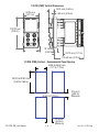
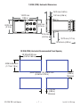
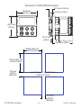
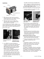
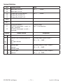
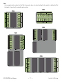
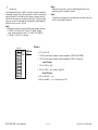
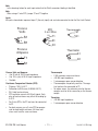
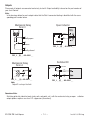
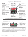
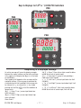
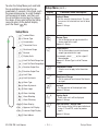
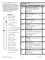
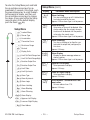
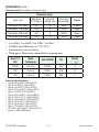
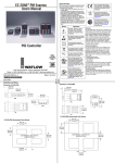
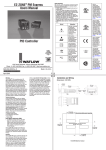
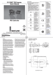
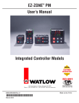
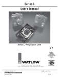
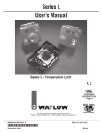
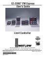
EZ-ZONE® PM Express User's Guide L I M I T L I M I T RESET RESET L I M I T RESET Limit Controller TOTAL CUSTOMER SATISFACTION 3 Year Warranty ISO 9001 Registered Company Winona, Minnesota USA 1241 Bundy Boulevard., Winona, Minnesota USA 55987 Phone: +1 (507) 454-5300, Fax: +1 (507) 452-4507 http://www.watlow.com 0600-0066-0000 Rev. E Made in the U.S.A. April 2013 Safety Information We use note, caution and warning symbols throughout this book to draw your attention to important operational and safety information. A “NOTE” marks a short message to alert you to an important detail. A “CAUTION” safety alert appears with information that is important for protecting your equipment and performance. Be especially careful to read and follow all cautions that apply to your application. A “WARNING” safety alert appears with information that is important for protecting you, others and equipment from damage. Pay very close attention to all warnings that apply to your application. The electrical hazard symbol, (a lightning bolt in a triangle) precedes an electric shock hazard CAUTION or WARNING safety statement. Further explanations follow: Symbol Explanation CAUTION – Warning or Hazard that needs further explanation than label on unit can provide. Consult users manual for further information. ESD Sensitive product, use proper grounding and handling techniques when installing or servicing product. Unit protected by double/reinforced insulation for shock hazard prevention. Do not throw in trash, use proper recycling techniques or consult manufacturer for proper disposal. Unit can be powered with either alternating current (ac) voltage or direct current (dc) voltage. Unit is a Listed device per Underwriters Laboratories®. It has been evaluated to United States and Canadian requirements for Process Control Equipment. UL 61010 and CSA C22.2 No. 61010. File E185611 QUYX, QUYX7. See: www.ul.com Unit is compliant with European Union directives. See Declaration of Conformity for further details on Directives and Standards used for Compliance. Unit has been reviewed and approved by Factory Mutual as a Temperature Limit Device per FM Class 3545 standard. See: www.fmglobal.com Unit has been reviewed and approved by CSA International for use as Temperature Indicating-Regulating Equipment per CSA C22.2 No. 24. See: www.csa-international.org Warranty This EZ-ZONE® PM is manufactured by ISO 9001 registered processes and is backed by a three year warranty to the first purchaser for use, providing that the units have not been misapplied. Watlow's obligations hereunder, at Watlow's option, are limited to replacement, repair or refund of purchase price, and parts which upon examination prove to be defective within the warranty period specified. This warranty does not apply to damage resulting from transportation, alteration, misuse or abuse. The purchaser must use Watlow parts to maintain all listed ratings. EZ-ZONE PM Limit Express • 2 • Technical Assistance You can get assistance from your local Watlow representative (see back cover), send an email with your questions to: [email protected] or dial +1 (507) 494-5656 between 7 a.m. and 5 p.m. Central Standard Time (CST) and ask for an Applications Engineer. Please have the following information available when calling: • Complete model number • All configuration information • User's Manual • Factory Page The EZ-ZONE PM Controller User’s Guide is copyrighted by Watlow Electric, Inc., © April 2013 with all rights reserved. The EZ-ZONE PM is covered by U.S. Patent No. 6,005,577 and Patents Pending Product Overview The EZ-ZONE PM Express single loop Limit controller is available in 1/4, 8th, 16th or 32nd DIN panel-mount packages. Ordering options include high or low voltage units with up to two outputs. EZ-ZONE PM Limit Express • 3 • Installation and Wiring 1/32 DIN (PM3) Dimensions 15.9 mm (0.63 in) 101.6 mm (4.00 in) 31.2 mm (1.23 in) 53.3 mm (2.10 in) Side 30.9 mm (1.22 in) Front Top 1/32 DIN (PM3) Recommended Panel Spacing 44.96 to 45.47 mm (1.77 to 1.79 in) 22.2 to 22.5 mm (0.87 to 0.89 in) 21.6 mm (0.85 in) minimum 21.6 mm (0.85 in) EZ-ZONE PM Limit Express • 4 • Ins ta ll & W i r i n g 1/16 DIN (PM6) Dimensions 15.8 mm 53.3 mm (0.62 in) 101.6 mm (2.10 in) (4.00 in) 53.3 mm (2.10 in) Side Front 51.2 mm (2.02 in) Top 1/16 DIN (PM6) Recommended Panel Spacing 44.96 to 45.47 mm (1.77 to 1.79 in) 44.96 to 45.47 mm (1.77 to 1.79 in) panel thickness 1.53 to 9.52 mm (0.060 to 0.375 in) 21.6 mm (0.85 in) minimum 21.5 mm (0.85 in) EZ-ZONE PM Limit Express • 5 • Ins ta ll & W i r i n g 1/8 DIN (PM8) Vertical Dimensions 15.75 mm (0.62 in) 53.34 mm 1.52 mm (0.06 in) (2.10 in) 100.33 mm (3.95 in) 54.8 mm (2.16 in) 10.16 mm (0.40 in) 30.73 mm (1.21 in) 101.60 mm (4.00 in) 1/8 DIN (PM8) Vertical - Recommended Panel Spacing 44.96 to 45.60 mm (1.77 to 1.79 in) 92.00 to 92.80 mm (3.62 to 3.65 in) panel thickness 1.53 to 9.52 mm (0.060 to 0.375 in) EZ-ZONE PM Limit Express • 6 • 21.6 mm (0.85 in) Minimum 21.6 mm (0.85 in) Minimum Ins ta ll & W i r i n g 1/8 DIN (PM9) Horizontal Dimensions 15.75 mm (0.62 in) 100.33 mm (3.95 in) 1.52 mm (0.06 in) 53.8 mm (2.16 in) 53.34 mm (2.10 in) 10.16 mm (0.40 in) 30.73 mm (1.21 in) 101.60 mm (4.00 in) 1/8 DIN (PM9) Horizontal Recommended Panel Spacing 92.00 to 92.80 mm (3.62 to 3.65 in) 44.96 to 45.6 mm (1.77 to 1.79 in) panel thickness 1.53 to 9.52 mm (0.060 to 0.375 in) 21.6 mm (0.85 in) Minimum 21.6 mm (0.85 in) Minimum EZ-ZONE PM Limit Express • 7 • Ins ta ll & W i r i n g Dimensions 1/4 DIN (PM4) Dimensions 15.75 mm (0.62 in) 100.33 mm (3.05 in) 1.52 mm (0.06 in) 100.33 mm (3.95 in) 12.70 mm (0.50 in) 30.73 mm (1.21 in) 100.84 mm (3.97 in) 92.00 to 93.0 mm (3.62 to 3.65 in) 92.00 to 93.0 mm (3.62 to 3.65 in) 21.6 mm (0.85 in) Minimum panel thickness 1.53 to 9.52 mm (0.060 to 0.375 in) 21.6 mm (0.85 in) Minimum EZ-ZONE PM Limit Express • 8 • Ins ta ll & W i r i n g Installation CASE BEZEL the ridges on the sides of the controller. Each tooth is staggered at a different depth from the front so that only one of the tabs, on each side, is locked onto the ridges at a time. Removing the Mounted Controller from Its Case 1. From the controller's face, pull out the tab on each side until you hear it click. RETENTION COLLAR PANEL GASKET 1. Make the panel cutout using the mounting template dimensions in this chapter. Insert the case assembly into the panel cutout. Pull out the tab on each side until you hear it click. 2. While pressing the case assembly firmly against the panel, slide the mounting collar over the back of the controller. Grab the unit above and below the face and pull forward. 2.Once the sides are released, grab the unit above and below the face with two hands and pull the unit out. If it is difficult to pull the unit out, remove the connectors from the back of the controller. This should make it easier to remove. If the installation does not require a NEMA 4X seal, slide the mounting collar up to the back of the panel tight enough to eliminate the spacing between the gasket and the panel. Ó Warning: Slide the mounting collar over the back of the controller. Place the blade of a screwdriver in the notch of the mounting collar assembly. 3. For a NEMA 4X seal, place the blade of a screwdriver in the notch of the mounting collar assembly and push toward the panel while applying pressure to the face of the controller. Don't be afraid to apply enough pressure to properly install the controller. The seal system is compressed more by mat- ing the mounting collar tighter to the front panel (see picture). If you can move the case assembly back and forth in the cutout, you do not have a proper seal. The tabs on each side of the mounting collar have teeth that latch into EZ-ZONE PM Limit Express All electrical power to the controller and con- trolled circuits must be disconnected before removing the controller from the front panel or disconnecting other wiring. Returning the Controller to its Case 1.Ensure that the orientation of the controller is correct and slide it back into the housing. 2. Using your thumbs push on either side of the controller until both latches click. Note: The controller is keyed so if it feels that it will not slide back in do not force it. Check the ori- entation again and reinsert after correcting. • 9 • Chemical Compatibility This product is compatible with acids, weak alkalis, alcohols, gamma radiation and ultraviolet radiation. This product is not compatible with strong alkalis, organic solvents, fuels, aromatic hydrocarbons, chlorinated hydrocarbons, esters and keytones. Ins ta ll & W i r i n g Terminal Definitions Slot C Terminal Function Model 98 99 power input: ac or dc+ power input: ac or dc- PM _L_ _ _ - AAAAB _ _ CF CD CE Standard Bus EIA-485 common Standard Bus EIA-485 T-/RStandard Bus EIA-485 T+/R+ PM _L_ _ _ - AAAAB _ _ S2 (RTD) or current +, S3 (RTD), thermocouple -, current - or volts -, thermistor S1 (RTD), thermocouple + or volts +, thermistor Universal Sensor input 1: all configurations Slot A Input 1 T1 S1 R1 Outputs 1 Terminal Function Configuration 2 X1 W1 Y1 common (Any switched dc output can use.) dc- (open collector) dc+ Switched dc/open collector, output 1: PM _L_ (C) _-_ AAAB _ _ L1 K1 J1 normally open common normally closed Mechanical Relay 5 A, Form C, output 1: PM _L_ (E) _-_ AAAB _ _ normally open common Mechanical Relay 5 A, Form A, output 2: PM _L_ _ (J)-_ AAAB _ _ L2 K2 EZ-ZONE PM Limit Express • 10 • Ins ta ll & W i r i n g Note: In the graphics below notice that the Slot A connector does not show labeling for the outputs. Labeling for Slot A outputs is based on the controller part number. PM3 PM6 98 Output 1 98 99 CF CD CE C 99 CF Output 2 CD A CE Output 1 T1 Output 2 T1 S1 R1 S1 R1 A PM4 C B 98 98 T1 99 S1 99 Communications Card Output 2 Output 1 Digital I/O 7 - 12 Output 1 PM8 CF CD CE R1 CF Output 2 A CD D E C Output 3 CE T1 Output 4 S1 R1 E C Input 2 A PM9 D D 99 CF Output 2 Input 2 B 98 Output 1 Output 4 Digital I/O 7 - 12 Output 3 B CD CE T1 S1 R1 A EZ-ZONE PM Limit Express B • 11 • D E C Ins ta ll & W i r i n g Ó Warning: Use National Electric (NEC) or other country-specific standard wiring and safety practices when wiring and connecting this controller to a power source and to electrical sensors or peripheral devices. Failure to do so may result in damage to equipment and property, and/or injury or loss of life. Note: Maximum wire size termination and torque rating: • 0.0507 to 3.30 mm2 (30 to 12 AWG) single- wire termination or two 1.31 mm2 (16 AWG) • 0.8 Nm (7.0 lb.-in.) torque Note: Adjacent terminals may be labeled differently, depending on the model number. Note: To prevent damage to the controller, do not connect wires to unused terminals. Power Slot C 98 99 power power CF CD CE fuse • 47 to 63 Hz • 10VA maximum power consumption (PM3 and PM6) • 14VA maximum power consumption (PM4, 8 and 9) Low Power • 12 to 40VÎ (dc) • 20 to 28VÅ (ac) Semi Sig F47 High Power Power EZ-ZONE PM Limit Express • 85 to 264VÅ (ac) •100 to 240VÅ (ac) Semi Sig F47 • 12 • Ins ta ll & W i r i n g Note: In the drawings below for each input notice that the Slot A connector labeling is identified. Note: When using a 2 wire RTD, jumper S1 and T1 together Inputs All inputs shown below represent input 1 (the only input) and are to be connected to slot A of the Limit Control. Process Volts - S1 RTD 2 or 3 Wire S2 T1 S3 + R1 S1 Thermocouple - S1 + R1 S1 R1 Process Amperes Thermistor S1 + T1 - R1 S1 Process Volts and Amperes • 4 to 20 mA @ 100 Ω input impedance • 0 to 10VÎ (dc) @ 20 kΩ input impedance • Scalable Resistance Temperature Detector (RTD) • Platinum, 100 Ω @ 0°C • Calibration to DIN curve (0.00385 Ω/Ω/°C) • 20 Ω total lead resistance • RTD excitation current of 0.09 mA typical. Each ohm of lead resistance may affect the reading by 0.03°C. • For 3-wire RTDs, the S1 lead must be connected to R1. • For best accuracy use a 3-wire RTD to compensate for lead-length resistance. All three lead wires must have the same resistance. EZ-ZONE PM Limit Express Thermocouple • 2 KΩ maximum source resistance • >20 MΩ input impedance • 3 microampere open-sensor detection • Thermocouples are polarity sensitive. The negative lead must be connected to S1. • To reduce errors, the extension wire for thermocouples must be of the same alloy as the thermocouple. Thermistor • >20 MΩ input impedance • 3 microampere open-sensor detection • 13 • Ins ta ll & W i r i n g Outputs Please note all outputs are connected exclusively to slot A. Output availability is based on the part number of your Limit Control. Note: In the drawings below for each output notice that the Slot A connector labeling is identified with the corresponding part number below. Mechanical Relay Form C Open Collector Power Supply common X1 L1 normally open dc W1 Load K1 common PM _ L _ (C) _ - A A A A B _ _ J1 normally closed PM _ L _ (E) _ - A A A A B _ _ Switched DC Mechanical Relay Form A common L2 dc W1 dc + Y1 K2 PM _ L _ _ (J) - A A A A B _ _ PM _ L _ (C) _ - A A A A B _ _ Note: Output 2 is always the limit. Quencharc Note: Switching pilot duty inductive loads (relay coils, solenoids, etc.) with the mechanical relay, or open output options requires use of an R.C. suppressor (Quencharc). EZ-ZONE PM Limit Express • 14 • collector Ins ta ll & W i r i n g Outputs (cont.) Switched DC • 22 to 32VÎ(dc) @ 30mA maximum supply current • short circuit limited to <50 mA • 22 to 32VÎ(dc) open circuit voltage • Use dc- and dc+ to drive external solid-state relay. • DIN-a-mite compatibility is for output 1 only. - single-pole: up to 4 in parallel or 4 in series - 2-pole: up to 2 in parallel or 2 in series - 3-pole: up to 2 in series Open Collector • 100 mA maximum output current sink • 30VÎ (dc) maximum supply voltage • Use an external power supply to control a dc load, with the load positive to the positive of the power supply, the load negative to the open collector and common to the power supply negative. See Quencharc note. Mechanical Relay Form C • 5 A at 240VÅ (ac) or 30VÎ (dc) maximum resistive load, output 1 • 20 mA at 24V minimum load • 125 VA pilot duty at 120/240VÅ (ac), 25 VA at 24VÅ (ac) • 100,000 cycles at rated load • Output does not supply power. • for use with ac or dc See Quencharc note. Mechanical Relay Form A • 5 A at 240VÅ (ac) or 30VÎ (dc) maximum resistive load, output 2 • 20 mV at 24V minimum load • 125 VA pilot duty @ 120/240VÅ (ac), 25 VA at 24VÅ (ac) • 100,000 cycles at rated load • Output does not supply power. • for use with ac or dc See Quencharc note (previous page). EZ-ZONE PM Limit Express • 15 • Ins ta ll & W i r i n g Keys & Displays 16th DIN LIMIT Controller Zone Display: When [2onE] (found in the Factory Page) is set to on, indicates the controller zone. [1] to [9] = zones 1 to 9 [A] = zone 10 [E] = zone 14 [b] = zone 11 [F] = zone 15 [C] = zone 12 [h] = zone 16 [d] = zone 13 Upper Display: On power up, displays the process value, otherwise displays the value of the parameter in the lower display. PM6 ® L I M I T Lower Display: Indicates the current state of the limit [Fail] or [Safe]. Output Activity: Number lights indicate activity of outputs 1 and 2. Communications Activity: Flashes when another device is communicating with this controller. EZ Key: Performs reset function. RESET Key: Press to reset limit after a trip condition has been cleared. Temperature Units Indicator Lights: Indicates whether the temperature is displayed in Fahrenheit or Celsius. Up and Down Keys: ¿ ¯ When in a menu scrolls through available options for any given prompt. In other menus can change set points and modify the upper display to a higher or lower value. Advance Key: ‰ Advances through parameter prompts. Upon power-up, the upper display will briefly indicate the firmware revision and the lower display will show PMb. The "b" in this case, reflects the B in the model number. 32nd DIN LIMIT Controller With a few exceptions, all of the key functions described above for the 16th DIN LIMIT apply to the 32nd DIN LIMIT controller as well. Left Display: On power up, displays the process value, otherwise displays the value of the parameter in the right display. PM3 L I M I T 1 2 ® Right Display: Indicates the current state of the limit [Fail] or [Safe]. Note: As shown in the graphics on the following page the PM4, 8 and 9 controls will include two "EZ" buttons (EZ1 and EZ2). The button identified as EZ1 is equivalent to the EZ button described above where the button identified as EZ2 has no functionality. Assuming the issue that caused the limit to trip has been rectified pushing the EZ1 will reset the limit as described for the Reset button above. All other buttons found on these controls, maintain the same functionality as described above for the 16th DIN. EZ-ZONE PM Limit Express • 16 • Ke y s & D i s p l a y s Keys & Displays for 1/8th or 1/4 DIN PID Controllers PM9 ® PM8 ® L I M I T L I M I T RESET PM4 ® RESET L I M I T Responding to a Displayed Message An active message will cause the display to toggle between the normal settings and the active message in the upper or left display and [Attn] in the lower or right display. Your response will depend on the message and the controller settings. If the message is generated by a latched alarm or limit condition, the message can be silenced [Sil] or cleared [CLr] by simply pushing the reset key when the condition no longer exists. [AL;L1] Alarm 1 Low (sensor input below low alarm set point) [AL;h1] Alarm 1 High (sensor input above high alarm set point) Alarm Error 1 EZ-ZONE PM Limit Express [AL;E1] Alarm 1 Error (alarm state cannot be determined due to lack of sensor input) [Er;i1] Error Input 1 (sensor is not providing a valid signal to the control) [Li;L1] Limit Low 1 (sensor input below low limit set point) [Li;h1] Limit High 1(sensor input above high limit set point) [Li;E1] Li mit Error 1 (limit state cannot be determined due to lack of sensor input, limit will trip • 17 • Ke y s & D i s p l a y s Upon power up of the control, using the advance key will scroll through the various prompts found in the Operations Menu. At any point within the Operations menu to return to the default display push the Reset key. Operations Menu Display [`LL;S] [ LL.S] Limit Low Set Point Set the low process value that will trigger the limit. Appears if: Limit sides set to low or both. [`Lh;S] [ Lh.S] Limit High Set Point Set the high process value that will trigger the limit. Appears if: Limit sides set to high or both. [`A;Lo] [ A.Lo] Alarm Low Set Point Process - set the process value that will trigger a low alarm. Appears if: Alarm Type (A.ty) is set to Process Alarm [`A;hi] [ A.hi] Alarm High Set Point Process - set the process value that will trigger a high alarm. Appears if: Alarm Type (A.ty) is set to Process Alarm [`i;CA] [ i.CA] Calibration Offset Set an offset value for a process output. Appears if: Always Operations Menu [````] PAr1 ‰ [````] PAr2 [`ll;s] Limit Low Set Point [`lh;s]Limit High Set Point [`A;lo]Alarm Low Point [`A;hi]Alarm High Point [`i;Ca]Calibration Offset EZ-ZONE PM Limit Express Parameter Name Description • 18 • Ope r a ti o n s Me n u Range Defaults are shown bold -1,999.000 to 9,999.000°F or units -1,128.000 to 5,537.000°C Units, 0.0°F or -18.0°C -1,999.000 to 9,999.000°F or units -1,128.000 to 5,537.000°C Units, 0.0°F or -18.0°C -1,999.000 to 9,999.000°F or units -1,128.000 to 5,537.000°C Units, 32.0°F or 0.0°C -1,999.000 to 9,999.000°F or units -1,128.000 to 5,537.000°C Units, 300.0°F or 150.0°C -1,999.000 to 9,999.000°F or units -1,110.555 to 5,555.000°C 0.0 EZ-ZONE PM Limit Express • 19 • Ope r a ti o n s Me n u To enter the Setup Menu push and hold the up and down arrow keys for approximately 3 seconds. Once there, push the green advance key to scroll through to the prompt of choice and then use the up and down arrow keys to change the range. At any point within the Setup menu to return to the default display push the Reset key. Setup Menu Display LoC [LoC] Parameter Name Description Lockout Menu Set the security clearance level. The user can access the selected level and all lower levels. Appears if: Always Setup Menu [`loC] Lockout Menu ‰ [`SEn] Sensor Type [Sen] [ SEn] [`Lin] Linearization [``t;C] Thermistor Curve [``r;r] Resistance Range [`deC] Decimal [Lin] [ Lin] Linearization Set the linearization to match the thermocouple type wired to this input. For example, select [```H] for a type K thermocouple. Appears if: Sensor Type is set to Thermocouple. [``t;C] [ t.C] Thermistor Curve Select a curve to apply to the thermistor input. [``r;r] [ r.r] Resistance Range Set the maximum resistance of the thermistor input. [`C_F] Display Units [`r;lo] Limit Set Point Range Low [`r;hi] Limit Set Point Range High [`fn1] Function Output One [`fn2] Function Output Two [`l;sd] Limit Sides [`l;hy] Limit Hysteresis [`A;ty] Alarm Type [`A;hy] Alarm Hysteresis [`A;lg] Alarm Logic [`dEC] [ dEC] Decimal Set the precision of the displayed value. Appears if: Always. [`C_F] [ C_F] Display Units Select which units will be displayed. Appears if: Always. [`r;Lo] [ r.Lo] Limit Set Point - Range Low Sets the low limit of the set point adjustment using a T/C and RTD; scales for process inputs. Appears if: Always. [`A;lA] Alarm Latching [`A;bl] Alarm Blocking [`A;si] Alarm Silencing [A;dsp] Alarm Display [par1] Upper or Left Display [par2] Lower or Right Display [`Ad;s] Zone Address EZ-ZONE PM Limit Express Sensor Type Set the analog sensor type to match the device wired to this input. Appears if: Always. • 20 • Se tu p Me n u Range (Defaults are shown bold) 1 to 5 1 Operations Menu (read only)* 2 Operations Menu (Set point R/W)* 3 Operations Menu (Set point R/W, Control Mode R/W)* 4 Operations Menu R/W access)* 5 Operations Menu and Setup Menu full R/W access *You can change the security level at any level [``tC] Thermocouple [uolT] Volts dc [`b] [`c] [`d] [`e] [`f] B C D E F [`J] [`H] [`n] [`r] [`S] J K N R S [`MA] Milliamps dc [r0;1H] RTD 100 Ω [`t] T [```A] Curve A, [```b] Curve B, [```C] Curve C [CUSt] Custom [```5] 5K, [``10] 10K, [``20] 20K, [``40] 40K [```0] Whole [``0;0] Tenths [`0;00] Hundredths [```F] °F [```C] °C -1,999.00 to 9,999.000 °F or Units -1,110.555 to 5,555.000 °C 0.0 EZ-ZONE PM Limit Express • 21 • Se tu p Me n u To enter the Setup Menu push and hold the up and down arrow keys for approximately 3 seconds. Once there, push the green advance key to scroll through to the prompt of choice and then use the up and down arrow keys to change the range. At any point within the Setup menu to return to the default display push the Reset key. Setup Menu [`loC] Lockout Menu ‰ Setup Menu (cont.) Display Parameter Name Description [`r;hi] [ r.hi] Limit Set Point - Range High Sets the high limit of the set point adjustment using a T/C and RTD; scales for process inputs. Appears if: Always. [`fn1] [ fn1] Function of Output 1 Select which function will drive this output. Appears if: Always. [`fn2] [ fn2] Function of Output 2 Select which function will drive this output. Appears if: Always. [`L;Sd] [ L.Sd] Limit Sides Select which side or sides of the process value will be monitored. Appears if: Always. [`L;hy] [ L.hy] Limit Hysteresis Set the hysteresis for the limit function. This determines how far into the safe range the process value must move before the limit turns the output back on. Appears if: Always. [`A;ty] [ A.ty] Alarm Type Select how the alarm will or will not track the set point. Appears if: Always. [`A;hy] [ A.hy] Alarm Hysteresis Set the hysteresis for an alarm. This determines how far into the safe region the process value needs to move before the alarm can be cleared. Appears if: When alarm type is set to process. [a;lg] [A.Lg] Alarm Logic Select what the output condition will be during the alarm state. Appears if: Always [`SEn] Sensor Type [`Lin] Linearization [``t;C] Thermistor Curve [``r;r] Resistance Range [`deC] Decimal [`C_F] Display Units [`r;lo] Limit Set Point Range Low [`r;hi] Limit Set Point Range High [`fn1] Function Output One [`fn2] Function Output Two [`l;sd] Limit Sides [`l;hy] Limit Hysteresis [`A;ty] Alarm Type [`A;hy] Alarm Hysteresis [`A;lg] Alarm Logic [`A;lA] Alarm Latching [`A;bl] Alarm Blocking [`A;si] Alarm Silencing [A;dsp] Alarm Display [par1] Upper or Left Display [par2] Lower or Right Display [`Ad;s] Zone Address EZ-ZONE PM Limit Express • 22 • Se tu p Me n u Range (Defaults are shown bold) -1,999.00 to 9,999.000 °F or Units -1,110.555 to 5,555.000 °C [`oFF] Off, [LiM] Limit*, [ALM] Alarm *Note: Switched DC/Open Collector option should only be used to control an external mechanical relay if Limit function is selected. [`LiM] Limit Note: Output 2 (only) is FM approved as a limit. [both] Both [high] High [LoW] Low 0.001 to 9,999.0°F or units 0.001 to 5,555.0°C Units, 3.0°F or 2°C [`oFF] Off [PR;AL] Process Alarm 0.001 to 9,999.000°F or units 0.001 to 5,555.000°C Units, 1.0°F or 1.0°C [`a;lC] Close on Alarm [`a;lo] Open on alarm EZ-ZONE PM Limit Express • 23 • Se tu p Me n u To enter the Setup Menu push and hold the up and down arrow keys for approximately 3 seconds. Once there, push the green advance key to scroll through to the prompt of choice and then use the up and down arrow keys to change the range. At any point within the Setup menu to return to the default display push the Reset key. Setup Menu (cont.) Display LoC [LoC] Parameter Name Description Lockout Menu Set the security clearance level. The user can access the selected level and all lower levels. Appears if: Always Setup Menu [`loC] Lockout Menu ‰ [`SEn] Sensor Type [Sen] [ SEn] [`Lin] Linearization [``t;C] Thermistor Curve [``r;r] Resistance Range [`deC] Decimal [Lin] [ Lin] Linearization Set the linearization to match the thermocouple type wired to this input. For example, select [```H] for a type K thermocouple. Appears if: Sensor Type is set to Thermocouple. [``t;C] [ t.C] Thermistor Curve Select a curve to apply to the thermistor input. [``r;r] [ r.r] Resistance Range Set the maximum resistance of the thermistor input. [`C_F] Display Units [`r;lo] Limit Set Point Range Low [`r;hi] Limit Set Point Range High [`fn1] Function Output One [`fn2] Function Output Two [`l;sd] Limit Sides [`l;hy] Limit Hysteresis [`A;ty] Alarm Type [`A;hy] Alarm Hysteresis [`A;lg] Alarm Logic [`dEC] [ dEC] Decimal Set the precision of the displayed value. Appears if: Always. [`C_F] [ C_F] Display Units Select which units will be displayed. Appears if: Always. [`r;Lo] [ r.Lo] Limit Set Point - Range Low Sets the low limit of the set point adjustment using a T/C and RTD; scales for process inputs. Appears if: Always. [`A;lA] Alarm Latching [`A;bl] Alarm Blocking [`A;si] Alarm Silencing [A;dsp] Alarm Display [par1] Upper or Left Display [par2] Lower or Right Display [`Ad;s] Zone Address EZ-ZONE PM Limit Express Sensor Type Set the analog sensor type to match the device wired to this input. Appears if: Always. • 24 • Se tu p Me n u Range (Defaults are shown bold) 1 to 5 1 Operations Menu (read only)* 2 Operations Menu (Set point R/W)* 3 Operations Menu (Set point R/W, Control Mode R/W)* 4 Operations Menu R/W access)* 5 Operations Menu and Setup Menu full R/W access *You can change the security level at any level [``tC] Thermocouple [uolT] Volts dc [`b] [`c] [`d] [`e] [`f] B C D E F [`J] [`H] [`n] [`r] [`S] J K N R S [`MA] Milliamps dc [r0;1H] RTD 100 Ω [`t] T [```A] Curve A, [```b] Curve B, [```C] Curve C [CUSt] Custom [```5] 5K, [``10] 10K, [``20] 20K, [``40] 40K [```0] Whole [``0;0] Tenths [`0;00] Hundredths [```F] °F [```C] °C -1,999.00 to 9,999.000 °F or Units -1,110.555 to 5,555.000 °C 0.0 EZ-ZONE PM Limit Express • 25 • Se tu p Me n u To enter the Setup Menu push and hold the up and down arrow keys for approximately 3 seconds. Once there, push the green advance key to scroll through to the prompt of choice and then use the up and down arrow keys to change the range. At any point within the Setup menu to return to the default display push the Reset key. Setup Menu [`loC] Lockout Menu ‰ Setup Menu (cont.) Display Parameter Name Description [`r;hi] [ r.hi] Limit Set Point - Range High Sets the high limit of the set point adjustment using a T/C and RTD; scales for process inputs. Appears if: Always. [`fn1] [ fn1] Function of Output 1 Select which function will drive this output. Appears if: Always. [`fn2] [ fn2] Function of Output 2 Select which function will drive this output. Appears if: Always. [`L;Sd] [ L.Sd] Limit Sides Select which side or sides of the process value will be monitored. Appears if: Always. [`L;hy] [ L.hy] Limit Hysteresis Set the hysteresis for the limit function. This determines how far into the safe range the process value must move before the limit turns the output back on. Appears if: Always. [`A;ty] [ A.ty] Alarm Type Select how the alarm will or will not track the set point. Appears if: Always. [`A;hy] [ A.hy] Alarm Hysteresis Set the hysteresis for an alarm. This determines how far into the safe region the process value needs to move before the alarm can be cleared. Appears if: When alarm type is set to process. [a;lg] [A.Lg] Alarm Logic Select what the output condition will be during the alarm state. Appears if: Always [`SEn] Sensor Type [`Lin] Linearization [``t;C] Thermistor Curve [``r;r] Resistance Range [`deC] Decimal [`C_F] Display Units [`r;lo] Limit Set Point Range Low [`r;hi] Limit Set Point Range High [`fn1] Function Output One [`fn2] Function Output Two [`l;sd] Limit Sides [`l;hy] Limit Hysteresis [`A;ty] Alarm Type [`A;hy] Alarm Hysteresis [`A;lg] Alarm Logic [`A;lA] Alarm Latching [`A;bl] Alarm Blocking [`A;si] Alarm Silencing [A;dsp] Alarm Display [par1] Upper or Left Display [par2] Lower or Right Display [`Ad;s] Zone Address EZ-ZONE PM Limit Express • 26 • Se tu p Me n u Range (Defaults are shown bold) -1,999.00 to 9,999.000 °F or Units -1,110.555 to 5,555.000 °C [`oFF] Off, [LiM] Limit*, [ALM] Alarm *Note: Switched DC/Open Collector option should only be used to control an external mechanical relay if Limit function is selected. [`LiM] Limit Note: Output 2 (only) is FM approved as a limit. [both] Both [high] High [LoW] Low 0.001 to 9,999.0°F or units 0.001 to 5,555.0°C Units, 3.0°F or 2°C [`oFF] Off [PR;AL] Process Alarm 0.001 to 9,999.000°F or units 0.001 to 5,555.000°C Units, 1.0°F or 1.0°C [`a;lC] Close on Alarm [`a;lo] Open on alarm EZ-ZONE PM Limit Express • 27 • Se tu p Me n u To enter the Setup Menu push and hold the up and down arrow keys for approximately 3 seconds. Once there, push the green advance key to scroll through to the prompt of choice and then use the up and down arrow keys to change the range. At any point within the Setup menu to return to the default display push the Reset key. Setup Menu Setup Menu (cont.) Display Alarm Latching Turn alarm latching on or off. A latched alarm has to be turned off by the user. Appears if: When alarm type is set to process. `A;bL] [ A.bL] Alarm Blocking Select when an alarm will be blocked. After startup and/or after the set point changes, the alarm will be blocked until the process value enters the normal range. Appears if: When alarm type is set to process. [`A;si] [ A.Si] Alarm Silencing Turn alarm silencing on to allow the user to disable the output tied (configured) to this alarm Appears if: Always. [A;dSP] [A.dSP] Alarm Display Display an alarm message when an alarm is active. Appears if: When alarm type is set to process. [PAr1] [PAr1] Upper or Left Display Select parameter to display. Appears if: Always. [PAr2] [PAr2] Lower or Right Display Select parameter to display. Appears if: Always. [`ad;s] [ Ad.S] Zone Address - Standard Bus Communication Set zone address from 1-16. Appears if: Always. [`loC] Lockout Menu ‰ [`SEn] Sensor Type [`Lin] Linearization [``t;C] Thermistor Curve [``r;r] Resistance Range [`deC] Decimal [`C_F] Display Units [`r;lo] Limit Set Point Range Low [`r;hi] Limit Set Point Range High [`fn1] Function Output One [`fn2] Function Output Two [`l;sd] Limit Sides [`l;hy] Limit Hysteresis [`A;ty] Alarm Type [`A;hy] Alarm Hysteresis [`A;lg] Alarm Logic Parameter Name Description [`A;LA] [ A.LA] [`A;lA] Alarm Latching [`A;bl] Alarm Blocking [`A;si] Alarm Silencing [A;dsp] Alarm Display [par1] Upper or Left Display [par2] Lower or Right Display [`Ad;s] Zone Address EZ-ZONE PM Limit Express • 28 • Se tu p Me n u Range (Defaults are shown bold) [nLAt] Non-Latching [`LAt] Latching [`oFF] Off [`Str] Startup [StPt] Set Point [both] Both [`oFF] Off [``on] On [`oFF] Off [``on] On [AC;Pu] Active Process Value [none] None [`Ls;t] Limit State [`Lh;S] Limit High Set Point [`LL;S] Limit Low Set Point [`A;hi] Alarm High Set Point [`A;lo] Alarm Low Set Point [none] None 1-16 1 EZ-ZONE PM Limit Express • 29 • Se tu p Me n u Specifications Line Voltage/Power • All voltage levels represent minimums and maximums • 85 to 264V~(ac), 47 to 63Hz • 20 to 28VÅ(ac), +10/-15 percent; 50/60Hz, ±5 percent • 12 to 40VÎ(dc) • 10VA maximum power consumption (PM3 and PM6) • 14VA maximum power consumption (PM4, 8 and 9) • Data retention upon power failure via nonvolatile memory • Compliant with SEMI F47-0200, Figure R1-1 voltage sag requirements @ 24VÅ(ac) or higher Environment • -18 to 65°C (0 to 149°F) operating temperature • -40 to 85°C (-40 to 185°F) storage temperature • 0 to 90 percent RH, non-condensing Accuracy • Calibration accuracy and sensor conformity: ±0.1 percent of span, ±1°C @ the calibrated ambient temperature and rated line voltage • Type S, 0.2 percent • Type T, below -50°C; 0.2 percent • Calibration ambient temperature @ 25°C ±3°C (77°F ±5°F) • Accuracy span: 540°C (1000°F) minimum • Temperature stability: ±0.1°C/°C (±0.1°F/°F) rise in ambient maximum Agency Approvals • cULus® UL/EN/CSA C22.2 No. 61010-1 Listed File E185611 • cULus® ANSI/ISA 12.12.01-2007, CSA-C22.2 No.213-1987, Class 1 Division 2 Groups A, B, C and D, Temperature Code T4A, File E184390 (optional) • UL® 50, 4X indoor locations, NEMA 4X, IP66 front seal • CSA C22.2 No. 24 File 158031 (1/32 and 1/16 DIN sizes) • CE, RoHS by design, W.E.E.E. • FM Class 3545 File 3029084 • SEMI F47-0200 Serial Communications • Isolated communications • Standard Bus Configuration Protocol Wiring Termination—Touch-Safe Terminals • Input, power and controller output terminals are touch safe removable 12 to 22 AWG • Use 75°C, Cu conductor only Universal Input • Thermocouple, grounded or ungrounded sensors • >20MΩinput impedance • Maximum of 2KΩ source resistance (applies to T/C only) • RTD 2- or 3-wire, platinum, 100Ω @ 0°C calibration to DIN curve (0.00385 Ω/Ω/°C) • Process, 4-20mA @ 100Ω, or 0-10VÎ(dc) @ 20kΩ input impedance; scalable EZ-ZONE PM Limit Express • 30 • Spec i fi c a ti o n s Specifications (cont.) Thermistor Input (Not included with Universal Input) Thermistor Input Input Type Max Error @ 25 Deg C Accuracy Range Low Accuracy Range High Units Thermistor, 5K range ±5 0 5000 Ohms Thermistor, 10K range ±10 0 10000 Ohms Thermistor, 20K range ±20 0 20000 Ohms Thermistor, 40K range ±40 0 40000 Ohms • • • • 0 to 40KΩ, 0 to 20KΩ, 0 to 10KΩ, 0 to 5KΩ 2.252KΩ and 10KΩ base at 77°F (25°C) Linearization curves built in Third party Thermistor compatibility requirements Base R @ 25C Alpha Techniques Beta THERM YSI Prompt [``tC] 2.252K Curve A 2.2K3A 004 A 10K Curve A 10K3A 016 B 10K Curve C 10K4A 006 C Functional Operating Range • Type B: -50 to 1816°C (-58 to 3301°F) • Type C: 0 to 2315°C (32 to 4199°F) • Type D: 0 to 2315°C (-328 to 4199°F) • Type E: -270 to 1000°C (-454 to 1832°F) • Type F: 0 to 1343°C (32 to 2449°F) • Type J: -210 to 1200°C (-346 to 2192°F) • Type K: -270 to 1371°C (-454 to 2500°F) • Type N: -200 to 1300°C (-328 to 2372°F) • Type R: -50 to 1767°C (-58 to 3213°F) • Type S: -50 to 1767°C (-58 to 3213°F) • Type T: -270 to 400°C (-454 to 752°F) • RTD (DIN): -200 to 800°C (-328 to 1472°F) • Process: -1999 to 9999 units EZ-ZONE PM Limit Express • 31 • Spec i fi c a ti o n s Specifications (cont.) Output Hardware • Switched dc - 22 to 32VÎ(dc) @ 30mA • Open collector, maximum sink current 100 mA, @ 30VÎ(dc) • Electromechanical relay, Form C, 5A, 24 to 240VÅ(ac) or 30VÎ(dc) maximum, resistive load, 100,000 cycles at rated load • Electromechanical relay, Form A, 5A, 24 to 240VÅ(ac) or 30VÎ(dc) maximum, resistive load, 100,000 cycles at rated load Operator Interface • Dual 4 digit, 7 segment LED displays • Typical display update rate 1Hz • Advance, RESET, up and down keys plus an EZ-Key/s (not available in 1/32 DIN) Ordering Part Number (Part number digits 1 through 14)PMXLXXX-AAAABXX All Models include: *Universal Sensor Input, Standard Bus Configuration Communications *Dual line Red over Green 7 Segment displays Package Size (Digit #3) 3 = 1/32 DIN 6 = 1/16 DIN 8 = 1/8 DIN vertical 9 = 1/8 DIN horizontal 4 = 1/4 DIN Primary Function (Digit #4) L = Limit Controller w/ Universal Input Power Supply (Digit #5) 1 = 100-240 VAC 3 = 12-28 VAC/DC Output 1 and 2 Hardware Options (Digits #6 and #7) Output 1 Output 2 AJ=None Mechanical relay 5A, Form A CJ =Switched dc/open collector Mechanical relay 5A, Form A EJ =Mechanical Relay 5 Amp form C Mechanical relay 5A, Form A Future Options (Digits #8 thru #11) AAAA=None Menu Type (Digits #12) B =Express Additional Options (Digits #13 and #14) AA= Standard EZ-ZONE face plate AB= EZ-ZONE logo and no Watlow name AC= No logo and no Watlow name EZ-ZONE PM Limit Express • 32 • Spec i fi c a ti o n s Declaration of Conformity Series EZ-ZONE® PM WATLOW an ISO 1241 Bundy Blvd. Winona, MN 55987 USA 9001 approved facility since 1996. Declares that the following product: Designation: Series EZ-ZONE® PM (Panel Mount) Model Numbers: PM (3, 6, 8, 9 or 4)(Any Letter or number) – (1, 2, 3 or 4)(A, C, E, F or K) (A, C, H, J or K)(Any letter or number) – (Any letter or number)(A, C, E, F or K)(A, C, H, J or K) (Any three letters or numbers) Classification: Temperature control, Installation Category II, Pollution degree 2, IP66 Rated Voltage and Frequency: 100 to 240 V~ (ac 50/60 Hz) or 15 to 36 V�dc/ 24 V~ac 50/60 Hz Rated Power Consumption: 10 VA maximum PM3, PM6 Models. 14 VA maximum PM8, PM9, PM4 Models Meets the essential requirements of the following European Union Directives by using the relevant standards show below to indicate compliance. 2004/108/EC Electromagnetic Compatibility Directive EN 61326-1 2006 EN 61000-4-2 EN 61000-4-3 EN 61000-4-4 EN 61000-4-5 EN 61000-4-6 EN 61000-4-11 EN 61000-3-2 EN 61000-3-31 SEMI F47 1996 +A1,A2 2006 2004 2006 1996 +A1,A2,A3 2004 2006 2005 2000 Electrical equipment for measurement, control and laboratory use – EMC requirements (Industrial Immunity, Class B Emissions). Electrostatic Discharge Immunity Radiated Field Immunity 10V/M 80–1000 MHz, 3 V/M 1.4–2.7 GHz Electrical Fast-Transient / Burst Immunity Surge Immunity Conducted Immunity Voltage Dips, Short Interruptions and Voltage Variations Immunity Harmonic Current Emissions Voltage Fluctuations and Flicker Specification for Semiconductor Sag Immunity Figure R1-1 1 For mechanical relay loads, cycle time may need to be extended up to 160 seconds to meet flicker requirements depending on load switched and source impedance. EN 61010-1 2006/95/EC Low-Voltage Directive 2001 Safety Requirements of electrical equipment for measurement, control and laboratory use. Part 1: General requirements Compliant with 2002/95/EC RoHS Directive Per 2002/96/EC W.E.E.E Directive Please Recycle Properly. Raymond D. Feller III Name of Authorized Representative Winona, Minnesota, USA Place of Issue General Manager Title of Authorized Representative June 2009 Date of Issue Signature of Authorized Representative CE DOC EZ-ZONE PM-06-09 EZ-ZONE PM Limit Express • 33 • How to Reach Us Corporate Headquarters Watlow Electric Manufacturing Company 12001 Lackland Road St. Louis, MO 63146 Sales: 1-800-WATLOW2 Manufacturing Support: 1-800-4WATLOW Email: [email protected] Website: www.watlow.com From outside the USA and Canada: Tel: +1 (314) 878-4600 Fax: +1 (314) 878-6814 Latin America Watlow de México S.A. de C.V. Av. Fundición No. 5 Col. Parques Industriales Querétaro, Qro. CP-76130 Mexico Tel: +52 442 217-6235 Fax: +52 442 217-6403 Europe Watlow France Tour d'Asnières. 4 Avenue Laurent Cély 92600 Asnières sur Seine France Tél: + 33 (0)1 41 32 79 70 Télécopie: + 33(0)1 47 33 36 57 Email: [email protected] Website: www.watlow.fr Watlow GmbH Postfach 11 65, Lauchwasenstr. 1 D-76709 Kronau Germany Tel: +49 (0) 7253 9400-0 Fax: +49 (0) 7253 9400-900 Email: [email protected] Website: www.watlow.de Watlow Italy S.r.l. Viale Italia 52/54 20094 Corsico MI Italy Tel: +39 024588841 Fax: +39 0245869954 Email: [email protected] Website: www.watlow.it Asia and Pacific Watlow Ibérica, S.L.U. C/Marte 12, Posterior, Local 9 E-28850 Torrejón de Ardoz Madrid - Spain T. +34 91 675 12 92 F. +34 91 648 73 80 Email: [email protected] Website: www.watlow.es Watlow UK Ltd. Linby Industrial Estate Linby, Nottingham, NG15 8AA United Kingdom Telephone: (0) 115 964 0777 Fax: (0) 115 964 0071 Email: [email protected] Website: www.watlow.co.uk From outside The United Kingdom: Tel: +44 115 964 0777 Fax: +44 115 964 0071 Watlow Singapore Pte Ltd. 16 Ayer Rajah Crescent, #06-03/04, Singapore 139965 Tel: +65 6773 9488 Fax: +65 6778 0323 Email: [email protected] Website: www.watlow.com.sg Watlow Korea Co., Ltd. #1406, E&C Dream Tower, 46, Yangpyeongdong-3ga Yeongdeungpo-gu, Seoul 150-103 Republic of Korea Tel: +82 (2) 2628-5770 Fax: +82 (2) 2628-5771 Website: www.watlow.co.kr Watlow Australia Pty., Ltd. 4/57 Sharps Road Tullamarine, VIC 3043 Australia Tel: +61 3 9335 6449 Fax: +61 3 9330 3566 Website: www.watlow.com Watlow Malaysia Sdn Bhd No. 14-3 Jalan 2/114 Kuchai Business Centre Jalan Kuchai Lama 58200 Kuala Lumpur Malaysia Tel: +60 3 7980 7741 Fax: +60 3 7980 7739 Watlow Electric Manufacturing (Shanghai) Company 1118 Fangyuan Road, Anting Industrial Park, Jiading, Shanghai, PRC 201203 People’s Republic of China Tel: +86 21 39509510 Fax: +86 21 5080-0906 Email: [email protected] Website: www.watlow.cn 䝵䔈爜榊㳮匰㦘棟⏻⚇ 浧楓ゑⓜ摠●ₒ影ℛ恾壮㲢⃚ 榊崀 ⍂䦮 Watlow Electric Taiwan Corporation 10F-1 No.189 Chi-Shen 2nd Road Kaohsiung 80143 Taiwan Tel: +886-7-2885168 Fax: +886-7-2885568 ዌእዊዙዘንዀኮዐ㪹㆞↩䯍 ᇽ㨀℻掌◒ⅲ䞿◉␔䯭䞿 Your Authorized Watlow Distributor ⥪⦌ኰወ⒴殷椝 Tel: 03-3518-6630 Fax: 03-3518-6632 Email: [email protected] Website: www.watlow.co.jp Watlow Japan Ltd. 1-14-4 Uchikanda, Chiyoda-Ku Tokyo 101-0047 Japan Tel: +81-3-3518-6630 Fax: +81-3-3518-6632 Email: [email protected] Website: www.watlow.co.jp TOTAL CUSTOMER SATISFACTION 3 Year Warranty EZ-ZONE PM Limit Express • 34 •