1
ENDAT-7703 USERS MANUAL
UNICORN COMPUTER CORP.
ENDAT-7703
User’s Manual
For ENDAT-7703 PCB ver. A2 or later
Sep.09.2015
1
ENDAT-7703 USERS MANUAL
UNICORN COMPUTER CORP.
Copyright Notice
The content of this manual has been checked for accuracy. The manufacturer
assumes no responsibility for any inaccuracies that may be contained in this
manual. The manufacturer reserves the right to make improvements or
modification to this document and/or the product at any time without prior
notice. No part of this document may be reproduced, transmitted, photocopied or
translated into any language, in any form or by any means, electronic, mechanical,
magnetic, optical or chemical, without the prior written permission of the
manufacturer.
Realtek is registered trademark of Realtek Technologies Inc.
Multiscan is a trademark of Sony Corp of America
IBM, EGA, VGA, PC/XT, PC/AT, OS/2 and PS/2 are registered trademarks of
International Business Machines Corporation
Intel® is a registered trademark of Intel Corporation
VIA is registered trademark of VIA Technology Incorporation
Plug and Play is registered trademarks of Intel Corporation
Microsoft, Windows and MS-DOS are trademarks of Microsoft Corporation
Award is a trademark of Phoenix Software Inc.
PCI is a registered trademark of PCI Special Interest Group
Other product names mentioned herein are used for identification purpose only and
may be trademarks and/or registered trademarks of their respective companies.
Installation Notice
The manufacturer recommends using a grounded plug to ensure proper
motherboard operation. Care should be used in proper conjunction with a
grounded power receptacle to avoid possible electrical shock. All integrated
circuits on this motherboard are sensitive to static electricity. To avoid
damaging components from electrostatic discharge, please do not remove
the board from the anti-static packing before discharging any static
electricity to your body, by wearing a wrist-grounding strap. The
manufacturer is not responsible for any damage to the motherboard due to
improper operation.
2
ENDAT-7703 USERS MANUAL
UNICORN COMPUTER CORP.
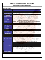
Specification:
Model
System Chipset
ENDAT-7703
Mobile Intel QM77 Express Chipset
Intel Ivy Bridge Core i3/i5/i7/Celeron mobile processor
CPU Supporting
Intel Sandy Bridge Core i3/i5/i7/Celeron mobile processor
2 x 204-Pin DDR3 SODIMM sockets
Memory
support DDR3-1066/1333/1600 up to 16 GB
2 x Intel Gb LAN support by 82583V + 82579LM (PHY)
Ethernet
Ivy Bridge CPU Built-In Intel HD Graphics 4000/2500
Sandy Bridge CPU Built-In Intel HD Graphics 3000/2000
VGA
Maximum resolution up to 2048x1536
Support 18/24/36/48bit LVDS with backlight control by standard
LVDS interface
(maximum resolution 1920 x 1200 )
CRT + DVI, CRT + LVDS, DVI+LVDS
Dual view
4 ports RS-232 with power selector (+12V / Ring-in / +5V)
Serial
feature by COM2
RS 422 / 485
TPM Security Chip SLB9635 (optional)
TPM
8.0
iAMT
1 x LPT with 2.0mm Box Header
LPT
2 ports SATA2 + 2 ports SATA3
SATA
USB 2.0 x 8 (4 external + 4 internal) & USB 3.0 (4 external)
USB
1 x 16 lanes PCIE slot +1 x single lane mini-PCIE socket
Expansion
On-chip supports 1 to 255 seconds / minutes
Watch Dog Timer
HD Audio with 1.2W amplifier
AUDIO
1 x 4 ports USB 2.0 connector
2 x USB 3.0 (2 ports) + 2 x RJ-45 connector
Back Panel I/O
1 x double deck D-SUB connector support COM1 + COM2
1 x double deck D-SUB connector support VGA + DVI
3 x Port Phone Jack for SPK-OUT/MIC/LINE-IN
PS2 Keyboard / Mouse with 2.54mm Pin Header
Speaker out, Line-in, CD-in, MIC-in with 2.54mm Pin Header
VGA / COM3 ~ COM4 / LPT1 with 2.0mm Box Header
4 x USB with 2.54mm Pin Header
Internal I/O
8-bits digital I/O for CMOS/TTL level
(4 bit input / 4 bit output) with 2.0mm Pin Header
1 x SPDIF with 2.0mm Pin Header
SIM Card Socket (optional)
ATX
Power Supply
MINI-ITX (170mm x 170mm) with 8 Layers PCB
Form Factor
3
ENDAT-7703 USERS MANUAL
UNICORN COMPUTER CORP.
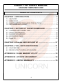
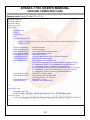
TABLE OF CONTENTS
CHAPTER 1. INTRODUCTION....................................................... 5
1-1.
1-2.
1-3.
1-4.
FEATURES ................................................................................................ 6
UNPACKING .............................................................................................. 7
ELECTROSTATIC DISCHARGE PRECAUTIONS .................................... 7
MOTHERBOARD LAYOUT........................................................................ 8
CHAPTER 2. SETTING UP THE MOTHERBOARD ....................... 9
2-1. JUMPERS AND CONNECTORS ............................................................... 9
2-2. INSTALLING MEMORY............................................................................ 23
2-3. SHARED VGA MEMORY......................................................................... 23
2-4. WATCH DOG TIMER ............................................................................... 23
2-5. Digital I/O……………………………………………………………………….25
CHAPTER 3. Phoenix UEFI BIOS SETUP .................................. 27
CHAPTER 4. VGA, SDVO AND DRIVERS................................... 31
4-1. VGA FEATURE......................................................................................... 31
4-2. DRIVER UTILITY INSTALLATION GUIDE............................................... 32
APPENDIX A: FLASH MEMORY UTILITY ................................... 33
APPENDIX B: LVDS PIN ASSIGNMENT ..................................... 34
APPENDIX C: LIMITED WARRANTY .......................................... 35
4
ENDAT-7703 USERS MANUAL
UNICORN COMPUTER CORP.
Chapter 1. Introduction
In order to cope with the challenges of the system performance issues and demand of much
more visually embedded system in diverse application, ENDAT-7703 system board provide
the ultimate solution with Intel® 32nm / 22nm Core i7/i5/i3/Celeron Processor with Socket
988 (FCPGA988) / Socket 988B (FCPGA988B).
This package offers a high performance Intel® CPU with optimal power efficiency on the
embedded market.
ENDAT-7703 supports Dual channel DDR3 1066/1333/1600 MHz memory. The
maximal capacity is up to 16GB.
ENDAT-7703
Intel Ivy Bridge CPU Intel HD Graphics 4000/2500 GPU core with 650MHz of base
frequency, Microsoft DirectX 11 support.
Intel Sandy Bridge CPU Intel HD Graphics 3000/2000 GPU core supports Microsoft DirectX
10.1 and OpenGL 3.0.
ENDAT-7703 supports not only Single Channel LVDS but also various kinds of
display include VGA and LVDS; Dual display is also feasible.
ENDAT-7703 provides one PCIe x16 slot and one Mini-PCIe x1 slot to support one
standard PCIe x16 and Mini-PCIe x1 interface.
The ideal solutions of ENDAT-7703
- POS system
- KIOSK
- Vehicle system
- Interactive system
- Industrial controller
- Gaming system
- Medical system
- Embedded system equipment
5
ENDAT-7703 USERS MANUAL
UNICORN COMPUTER CORP.
1-1.
Features
Basic Feature:
Intel® 32nm/ 22nm Core i7/i5/i3/Celeron Processor with Socket 988
(FCPGA988) / Socket 988B (FCPAG988B).
Dual channel DDR3 SO-DIMM socket supports 1066/1333/1600
MHz up to 16GB.
Dual PCI Express interface Gigabit Ethernet chip on-board.
Intel Ivy Bridge CPU Built-In Intel HD Graphics 4000/2500
Intel Sandy Bridge CPU Built-In Intel HD Graphics 3000/2000
PCI-E & Mini-PCIe slot support.
Built-in HD Audio with 1.2W amplifier.
Four fully functional serial ports.
Tow SATA 3.0 ports & Tow SATA 2.0 ports With SATA RAID 0/1/5/10
or AHCI.
Software Support
Drivers for major embedded operating systems: Linux, Windows7,
Windows XP, Windows XP embedded.
Ordering information:
Standard edition:
ENDAT-7703
6
ENDAT-7703 USERS MANUAL
UNICORN COMPUTER CORP.
1-2.
Unpacking
The motherboard comes securely packaged in a sturdy cardboard shipping carton. In
addition to the User's Manual, the motherboard package includes the following items:
ENDAT-7703 System Board
One SATA HDD Cable
LCD cable (Optional)
CD with Driver utilities for on-board chipsets, VGA and LAN adapter
If any of these items is missing or damage, please contact the dealer whom you purchase
the motherboard from. Save the shipping material and carton in the event that you want to
ship or store the board in the future.
Note: Leave the motherboard in its original package until you are ready to install it!
1-3.
Electrostatic Discharge Precautions
Make sure you properly ground yourself before handling the motherboard, or other system
components. Electrostatic discharge can easily damage the components. Note: You must
take special precaution when handling the motherboard in dry or air-conditioned
environments.
7
ENDAT-7703 USERS MANUAL
UNICORN COMPUTER CORP.
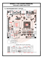
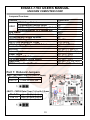
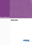
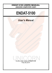
1-4. MOTHERBOARD LAYOUT.
8
ENDAT-7703 USERS MANUAL
UNICORN COMPUTER CORP.
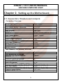
Chapter 2. Setting up the Motherboard
2-1. Connectors / Headers and Jumpers
Connectors Overview:
Function
Cooling Fan Connector
ATX Power Supply Connector
USB 2.0 Port
USB 3.0 Port
LAN Port
SATA Connector
DDR3 RAM Socket
CRT Output Connector
COM1,COM2 Connector
HD Audio Speaker Output
LCD Panel Connector
PCI-E x16 Slot
Mini PCI-E x1 Slot
Battery Socket
Connectors
FAN1, FAN2
ATXPWR
CN1
CN6, CN8
CN6, CN8
SATA1, SATA2, SATA3, SATA4
DIMM1, DIMM2
CN5
CN2
CN10
LVDS1
PCI-E1
MPCIE1
BAT1
Box Headers, Pin Headers Overview:
Function
PS/2 Mouse/KB Pin Header
External PS/2 Device Header
SPDIF Pin Header
Line-Out, CD-In Pin Header
Line-In、MIC-In Pin Header
USB Port Header
Reserved Power for LVDS1 (+3.3V)
VGA Box Header
Printer Port Box Header
COM Port Box Header
DIGITAL I/O Pin Header
Connectors
J1
JKBMS1
J8
J3
J7
J4, J6
JP6
VGA1
LPT1
CN3, CN4
J2
9
ENDAT-7703 USERS MANUAL
UNICORN COMPUTER CORP.
Jumpers Overview:
Function
LCD Voltage Select
LCD Backlight Voltage Select
LVDS1
LCD Backlight Control Voltage Select
LCD Backlight for +3.3 Voltage use
Clear CMOS
ME Clear
PS/2 Mouse/KB Voltage Selector
COM1/2/3/4 Voltage Selector
RS232 / 485 Selector for COM2
SATA1, 2, 3, 4, Pin7 Power/GND Select
Header for Case Panel
HDD LED
External Speaker
Buzzer On/Off
Hardware Reset Switch
ATX Power Supply On/Off Switch
Power LED
WDT Function Enable/Disable
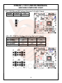
Part 1: Onboard Jumpers
JME1: ME Data Clear (1x3 with 2.0mm)
Normal
Pin 2-3 *
Close for clear ME
Pin 1-2
JBAT1: CMOS Data Clear (1x3 with 2.0mm)
Normal
Pin 2-3 *
Pin 1-2 Close for clear CMOS
10
Connectors
JP7
JP8
JP5
JP6
JBAT1
JME1
JP1
JP2, JP3
BIOS Setting
SATA12, SATA34
JP9
JP9: Pin 1(-), Pin 2(+)
JP9: Pin 4(-), Pin 10(+)
JP9: Pin 6, Pin 8
JP9: Pin 3, Pin 5
JP9: Pin 7, Pin 9
JP9: Pin 11(-), Pin 12(+)
JP9: Pin 13, Pin 14
ENDAT-7703 USERS MANUAL
UNICORN COMPUTER CORP.
JP1: PS/2 Mouse/KB Voltage Selector (1x3 with 2.0mm)
Voltage +5VSUS*
+5V
JP1
1-2
2-3
JP2, JP3: COM Port Voltage Selector (2x6 with 2.0mm)
Voltage
+12V(DC)
R.I. *
+5V(DC)
JP2 (COM1)
1-2
3-4
5-6
JP2 (COM2)
7-8
9-10
11-12
JP3 (COM3)
1-2
3-4
5-6
JP3 (COM4)
7-8
9-10
11-12
11
ENDAT-7703 USERS MANUAL
UNICORN COMPUTER CORP.
JP7: LCD Voltage Select (2x3 with 2.0mm)
Voltage
+3.3V *
+5V
JP7 (LVDS1)
1-2
3-4
+12V
5-6
JP8: LCD Backlight Voltage Select (1x3 with 2.0mm)
Voltage
+5V *
+12V
JP8 (LVDS1)
1-2
2-3
JP5: LCD Backlight Control Voltage Select (1x3 with 2.0mm)
Voltage
+3.3V *
+5V
JP5
1-2
2-3
JP6 LCD Backlight Voltage (for +3.3V)
Voltage
+3.3V
JP6
Output
12
ENDAT-7703 USERS MANUAL
UNICORN COMPUTER CORP.
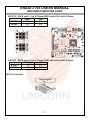
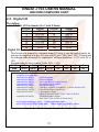
SATA12: SATA port1, 2 pin7 Power/GND select (2x3 with 2.0mm)
GND*
+5V
SATA1
1-3
3-5
SATA2
2-4
4-6
SATA34: SATA port3, 4 pin7 Power/GND select (2x3 with 2.0mm)
GND*
+5V
SATA3
1-3
3-5
SATA4
2-4
4-6
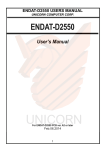
SATA Connector:
13
ENDAT-7703 USERS MANUAL
UNICORN COMPUTER CORP.
Part 2: Onboard Connectors and Headers
J1: PS/2 Keyboard / Mouse Header (2x5 with 2.54mm)
Pin No.
Signal
Pin No.
Signal
KB Data
MS Data
1
2
KEY
KEY
3
4
GND
GND
5
6
+5V(DC)
+5V(DC)
7
8
KB_CLK
MS_CLK
9
10
J8: SPDIF Header (1 x 5 with 2.0mm)
Pin No.
Signal
Pin No.
+5V
1
4
N.C
2
5
SPDIF-OUT
3
14
Signal
GND
SPDIF-IN
ENDAT-7703 USERS MANUAL
UNICORN COMPUTER CORP.
J3: LINE-OUT & CD-IN Header (2 x 4 with 2.54mm)
Pin No.
Signal
Pin No.
Signal
LINE_OUT_L
CD_IN_R
1
2
JACK_DETECT
GND_AUD
3
4
GND_AUD
GND_AUD
5
6
LINE_OUT_R
CD_IN_L
7
8
J7: LINE-IN & MIC-IN Header (2 x 4 with 2.54mm)
Pin No.
Signal
Pin No.
Signal
LINE_IN_R
MIC_ R
1
2
JACK_DETECT
JACK_DETECT
3
4
GND_AUD
GND_AUD
5
6
LINE_IN_L
MIC_ L
7
8
Notice: Please connect the jack detect pin to “GND_AUD” if the actual
connector cannot support the jack detect function!
15
ENDAT-7703 USERS MANUAL
UNICORN COMPUTER CORP.
CN10: 3 Ports Audio Jack
LINE IN
SPK OUT
MIC
J4, J6: Pin Header for USB ports (2x5 with 2.54mm)
Pin No.
Signal
Pin No.
Signal
USB_VCC
USB_VCC
1
2
USBD4-/6USBD5-/73
4
USBD4+/6+
USBD5+/7+
5
6
USB_GND
USB_GND
7
8
KEY
USB_GND
9
10
16
ENDAT-7703 USERS MANUAL
UNICORN COMPUTER CORP.
CN2: D-SUB Type Connector for COM1, 2 port (RS-232)
Pin No.
Signal
Pin No.
Signal
DCD
DSR
1
6
RXD
RTS
2
7
TXD
CTS
3
8
DTR
RI
4
9
GND
5
D-SUB Type Connector for COM2 port (RS-422 4 Wire)
Pin No.
Signal
Pin No.
Signal
–TXD
NA
1
6
+RXD
NA
2
7
+TXD
NA
3
8
–RXD
NA
4
9
NA
5
D-SUB Type Connector for COM2 port (RS-485 2 Wire)
Pin No.
Signal
Pin No.
Signal
Data –
NA
1
6
Data +
NA
2
7
NA
NA
3
8
NA
NA
4
9
NA
5
17
ENDAT-7703 USERS MANUAL
UNICORN COMPUTER CORP.
CN3 (COM3), CN4 (COM4): COM3~COM4 Box Headers (2x5 with 2.0mm)
Pin No.
Signal
Pin No.
Signal
DCD
DSR
1
6
RXD
RTS
2
7
TXD
CTS
3
8
DTR
RI
4
9
GND
N.C.
5
10
LPT1: Printer Port Box Header (2x13 with 2.0mm)
Pin No.
Signal
Pin No.
Signal
STB#
ACK#
1
10
PD0
BUSY
2
11
PD1
PE
3
12
PD2
SLCT
4
13
PD3
AFD#
5
14
PD4
ERR#
6
15
PD5
INIT#
7
16
PD6
SLIN#
8
17
PD7
GND
9
18-25
18
ENDAT-7703 USERS MANUAL
UNICORN COMPUTER CORP.
VGA1: CRT Box Header Connector (2x8 with 2.0mm)
Pin No.
Signal
Pin No.
Signal
RED
N.C.
1
9
GREEN
GND
2
10
BLUE
N.C.
3
11
N.C.
DDC DAT
4
12
GND
H-Sync
5
13
GND
V-Sync
6
14
GND
DDC CLK
7
15
GND
8
FAN1, FAN2: Cooling Fan Connector
Pin No.
Signal
GND
1
+12V
2
Sensor Pin
3
PWM(Fan1 Only)
4
19
ENDAT-7703 USERS MANUAL
UNICORN COMPUTER CORP.
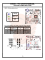
J2: DIGITAL I/O Pin Header (2 x 7 with 2.0mm)
Pin No.
Signal
Pin No.
Signal
+5V
+5V
1
2
DIO-O0
DIO-I0
3
4
DIO-O1
DIO-I1
5
6
GND
GND
7
8
DIO-O2
DIO-I2
9
10
DIO-O3
DIO-I3
11
12
+3.3V
+3.3V
13
14
20
ENDAT-7703 USERS MANUAL
UNICORN COMPUTER CORP.
LVDS1: Single /Dual Channel LVDS (18/24/36/48 bit, 1.25mm)
MB: DF-13A-40DP-1.25V / Map: DF13-40DS-1.25C
Pin No.
Signal
Pin No.
Signal
VBL
VBL
1
2
GND
GND
3
4
DISP.ON/OFF
GND
5
6
LCD POWER
LCD POWER
7
8
GND
GND
9
10
Odd 0+
Odd 011
12
Odd 1+
Odd 113
14
Odd 2+
Odd 215
16
Odd 3+
Odd 317
18
Odd CLK+
Odd CLK 19
20
GND
KEY
21
22
24
23
Even 0+
Even 0-.
25
26
Even 1+
Even 127
28
Even 2+
Even 229
30
Even 3+
Even 331
32
Even CLK+
Even CLKLCD POWER
LCD POWER
33
34
GND
GND
35
36
GND
GND
37
38
VBL
VBL
39
40
Please make sure the Pin 1 location before plug-in LCD connector.
Please leave pin 23rd ~ pin 32nd unconnected if the single channel LVDS
function is needed.
Please double check "jumper setting & LCD cable's orientation" before
power-on, any incorrect installation may caused damaged of the LCD.
21
ENDAT-7703 USERS MANUAL
UNICORN COMPUTER CORP.
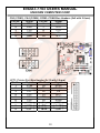
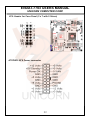
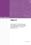
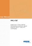
JP9: Header for Case Panel (2 x 7 with 2.54mm)
ATXPWR: ATX Power connector
22
ENDAT-7703 USERS MANUAL
UNICORN COMPUTER CORP.
2-2. Installing Memory
The DDR3 SO-DIMM sockets of ENDAT-7703 support up to 16GB. The speed of DDR3
memory can be DDR3 1066/1333/1600 MHz.
2-3. Shared VGA Memory
The ENDAT-7703 built-in Intel® HD graphic share memory; please refer to INTEL web site
link:
http://www.intel.com/support/graphics/sb/CS-029090.htm?wapkw=%22intel++graphics+me
dia+accelerator+3150+intel++gma+3150%22+hd+graphics+3000
2-4. Watch Dog Timer
Watch dog Timer (WDT) is a special design for system monitoring to secure the
system work normally. WDT has an independent clock from the oscillator and could
set time and clear/refresh WDT counter function. When time is up, WDT will send
hardware RESET signal to reset system.
Timeout Value Range
-1 to 255
-Second or Minute
23
ENDAT-7703 USERS MANUAL
UNICORN COMPUTER CORP.
Sample code (using TurboC/C++ 3.0):
#include <stdio.h>
#include <dos.h>
#include <dir.h>
void show_ver();
void main()
{
unsigned int tt;
clrscr();
show_ver();
tt=0;
while((tt==0)||(tt>255))
{
printf("\n\nPlease key in how many seconds you want to reset system (1~255):");
scanf("%d",&tt);
}
outportb(0x2e,0x87);
//Unlock register
outportb(0x2e,0x87);
//Unlock register
outportb(0x2e,0x07);
//set Logic Device number pointer
outportb(0x2f,0x08);
//set Logic Device number
outportb(0x2e,0x30);
//set WDTO active
outportb(0x2f,0x01);
//set reg value active (bit0 =1 active,0 inactive )
outportb(0x2e,0xf2);
//set WDTO Control Mode
outportb(0x2f,0x00);
//set register value Default :00h
//bit7 Mouse interrupt reset enables watch-dog timer reload
// 0: Watchdog Timer I is not affected by mouse interrupt.
// 1: Watchdog Timer I is reset by mouse interrupt.
// bit6 Keyboard interrupt reset enables watch-dog timer reload
// 0: Watchdog Timer I is not affected by keyboard interrupt.
// 1: Watchdog Timer I is reset by keyboard interrupt.
outportb(0x2e,0xf0);
//set WDTO Control Mode
outportb(0x2f,0x00);
//set register value Default :00h
// (bit3=1: minute. =0: second)
outportb(0x2e,0xf1);
//set WDT Counter
outportb(0x2f,tt);
//set time out value of WDT
}
void show_ver()
{
unsigned char tmp0;
printf("Designed by attila of UNICORN computer corp. \n2012/04/05 release
version:1.0a\n");
printf("This program is design for test Watch Dog Timer for ENADT-7703 (NCT6106D).\n");
}
24
ENDAT-7703 USERS MANUAL
UNICORN COMPUTER CORP.
2-5. Digital I/O
Pin define:
J2: DIGITAL I/O Pin Header (2 x 7 with 2.0mm)
Pin No.
Signal
Pin No.
+5V
1
2
DIO-O0
3
4
DIO-O1
5
6
GND
7
8
DIO-O2
9
10
DIO-O3
11
12
+3.3V
13
14
Signal
+5V
DIO-I0
DIO-I1
GND
DIO-I2
DIO-I3
+3.3V
Digital I/O port address:
This function is support by onboard super I/O chip; it can be control easily by
change the register of super I/O chip via I/O port “2Eh” and “2Fh”. Please see
the sample code of below for implement. Voltage tolerance: +/- 5% with 0V to
+5V.
Sample code for input (using Turbo C/C++ 3.0):
bit No
7
6
5
4
3
2
1
0
DIO-I3
DIO-I2
DIO-I1
DIO-I0
NA
NA
NA
NA
Map
Sample code for input (using Turbo C/C++ 3.0)
#define input_port 0x2f // Digital input data port
Unsigned char read_data;
outportb(0x2e,0x87);
//Unlock register
outportb(0x2e,0x87);
//Unlock register
outportb(0x2e,0x07);
//set Logic Device number pointer
outportb(0x2f,0x07);
//set Logic Device number
outportb(0x2e,0x30);
//set Device Active
outportb(0x2f,0x02);
// set Bit 2 =GPIO2 ; 0=Inactive / 1= Active Default: DFh
outportb(0x2e,0xE8);
// set GPIO Output / Input Port
outportb(0x2f,0xF0);
// 0=Output/ 1=Input
// Bit 0~3 DIO-O0~ DIO3 / Bit4~7 DIO-I0~DIO-I3.
outportb(0x2e,0xE9);
//Read DIO-Input register.
//Bit7~Bit4 = DIO-I3~DIO-I0.(Read Only)
read_data=inportb(input_port); // Read digital input data
printf("DIO-Input=%02X\n",read_data); //Show digital input data on screen
25
ENDAT-7703 USERS MANUAL
UNICORN COMPUTER CORP.
Sample code for output (using Turbo C/C++ 3.0):
bit No
7
6
5
4
3
2
NA
NA
NA
NA
DIO-O3
DIO-O2
Map
1
0
DIO-O1
DIO-O0
Sample code for output (using Turbo C/C++ 3.0)
outportb(0x2e,0x87);
outportb(0x2e,0x87);
outportb(0x2e,0x07);
outportb(0x2f,0x07);
outportb(0x2e,0x30);
outportb(0x2f,0x02);
outportb(0x2e,0xE8);
outportb(0x2f,0xF0);
outportb(0x2e,0xE9);
outportb(0x2f,0xnm);
//Unlock register
//Unlock register
//set Logic Device number pointer
//set Logic Device number
//set Device Active
// set Bit 2 =GPIO2 ; 0=Inactive / 1= Active Default: DFh
// set GPIO Output / Input Port
// 0=Output/ 1=Input
// Bit 0~3 DIO-O0~ DIO3 / Bit4~7 DIO-I0~DIO-I3.
//Read DIO-Input register.
// n=DIO-I0~DIO-I3 / m=DIO-O0~DIO-O3.
Bit7~Bit3 = DIO-I3~DIO-I0.(Read Only)
26
ENDAT-7703 USERS MANUAL
UNICORN COMPUTER CORP.
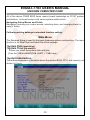
Chapter 3. Phoenix UEFI BIOS SETUP
Phoenix SecureCore Tiano Setup
BIOS menu screen
Setup Menu
The menu bar on top of the screen has the following main items:
> Main
For changing the basic system configuration.
> Advanced
For changing the advanced system setting.
> Super IO
For changing the system IO configuration.
> Security
For changing the security system setting.
> Boot
For changing the system boot configuration.
> Exit
For select the exit options and loading default setting.
Use the BIOS CMOS setup program to modify the system parameters to reflect the
environment installed in your system and to customize the system as desired.
Press the <F2> key to enter into the BIOS CMOS setup program when you turn on
the power. Settings can be accessed via arrow keys. Press <Enter> to choose an
option to configure the system properly.
In the main menu, press F10 or “Exit Saving Changes” to save your changes and
reboot the system. Choose “Exit Discarding Changes” to ignore the changes and
exit the setup procedure. Pressing <ESC> at anywhere during the setup will return
to the main menu.
27
ENDAT-7703 USERS MANUAL
UNICORN COMPUTER CORP.
All of the above CMOS BIOS items require board knowledge on PC/AT system
architecture. Incorrect setup could cause system malfunctions.
Navigating Setup Menus and Fields
Navigation (moving your cursor around, selecting items, and changing them) is
easy in Setup.
Following setting belongs to standard function setting:
Main Menu
The Standard Setup is used for the basic hardware system configuration. The main
function is for Data/Time and Hard Disk Drive settings.
˙System Date (mm:dd:yy)
˙System Time (hh:mm:ss)
Allows you to set the system date and time
(Use the TAB and BACKTAB (SHIFT + TAB) keys.)
˙System Information
This submenu provides information about the system BIOS, CPU, and memory, as
shown in Figure
28
ENDAT-7703 USERS MANUAL
UNICORN COMPUTER CORP.
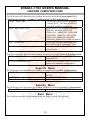
The following table describes the settings associated with the Boot Features.
Quick Boot
Enables OEM Logo
High Resolution Graphics
Enables high resolution graphics.
Diagnostic Splash Screen
Enables graphical POST, including
animation, sound, icons,
advertisements, and other multimedia
objects that may be configured by the
OEM.
Diagnostic Summary Screen
Enables the diagnostic summary
screen.
UEFI Boot
Enables the Unified Extensible
Firmware Interface.
Legacy Boot
Enable this option to bypass some
drivers and speed up POST.
Advanced Menu
The following table describes the settings associated with the Silicon Information.
This submenu provides information about the CPU.
The following table describes the settings associated with the HDD Configuration menu.
Interface Combination
Select the SATA controllers operation
mode.(IDE, AHCI, RAID0,1,5,10)
The following table describes the settings associated with the System Agent (SA)
Configuration menu – Graphics Configuration.
Primary Display Selection.
Select the primary display device.
29
ENDAT-7703 USERS MANUAL
UNICORN COMPUTER CORP.
The following table describes the settings associated with the System Agent (SA)
Configuration menu – Graphics Configuration- IGD Configuration.
IGD – Boot Type
Select the Video Device activated
during POST. This has no effect if
external graphics are present.
IGD – LCD Panel Type
Select LCD (LFP/LVDS) resolution.
640x480, 800x600, 1024x768,
1280x1024, 1440x1050, 1920x1080,
1600x1200, 1366x768, 1680x1050,
1920x1200, 1440x900, 800x480,
1024x600, 2048x1536, OEM resolution.
IGD – Active LFP
No LVDS: Disable OnBoard LVDS
Int-LVDS:Enable OnBoard LVDS
Panel Color Depth
Select the LCD (LFP/LVDS) Panel
Color Depth.
The following table describes the settings associated with the Network Configuration.
PCH Internal LAN
En/Disable PCH (Intel 82579LM)
Internal LAN.
LAN OPROM Selection
This is used to select LAN OPROM for
quick boot minimal configuration.
Super IO Menu
The following table describes the settings associated with the SIO Configuration.
COM2 Type
Select Serial 2 type: RS232, RS485,
RS422.
UART2 Termination
For RS485, RS422 Termination.
Power Failure – Power Control
Select Always On/Off, Former State.
Security Menu
The following table describes the settings associated with the Security Configuration.
Trusted Platform Module (TPM)
No support for ENDAT-7703.
Boot Menu
This submenu provides information about the Boot devices boot priority.
30
ENDAT-7703 USERS MANUAL
UNICORN COMPUTER CORP.
Chapter 4. VGA, SDVO and drivers
4-1.
Graphic controller Feature
• The Processor Graphics contains a refresh of the sixth generation graphics core
enabling substantial gains in performance and lower power consumption.
• Next Generation Intel Clear Video Technology HD support is a collection of video
playback and enhancement features that improve the end user’s viewing
experience.
— Encode/transcode HD content
— Playback of high definition content including Blue-ray Disc*
— Superior image quality with sharper, more colorful images
• DirectX* Video Acceleration (DXVA) support for accelerating video processing
— Full AVC/VC1/MPEG2 HW Decode
• Advanced Scheduler 2.0, 1.0, XPDM support
• Windows* 7, XP, Windows Vista*, OSX, Linux OS Support
• DX10.1, DX10, DX9 support
• OGL 3.0 support
31
ENDAT-7703 USERS MANUAL
UNICORN COMPUTER CORP.
4-2.
Driver Utility Installation Guide
1.
When finishing the installation of Windows XP, Vista, please install the relative Intel®
chipsets, display and audio driver manually for compliance compatibility of hardware
environment.
2.
Please contact sales department of UNICORN for Embedded OS user driver
(Linux, Windows CE and Windows XP embedded). All of embedded OS driver
is not be included in any versions of driver DVD-ROM from UNICORN.
Please download or check from Intel® web site: www.intel.com for more
information or last versions of driver as needs!
32
ENDAT-7703 USERS MANUAL
UNICORN COMPUTER CORP.
Appendix A: FLASH MEMORY UTILITY
Using this package to update the system BIOS from a disk file to the on board Flash memory.
Be aware any improper update of the system BIOS will cause the malfunction of the system.
Method of update BIOS:
1.
Please contact one of the Sales Representative on behalf of Unicorn to acquire
“BIOS update package”, and process following procedures for the BIOS UPDATE.
2.
Prepare a bootable storage that can boot under MS-DOS, (such as HDD, USB
sticker…etc)
3.
Unzip “BIOS Update package” into the bootable storage.
4.
Run the Flash file.
5.
Once the BIOS is Flash successfully, Reboot the system.
6.
Press <F2> to enter BIOS Setup, Load BIOS setup default <F9>, save BIOS
default and exit <F10>.
33
ENDAT-7703 USERS MANUAL
UNICORN COMPUTER CORP.
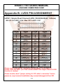
Appendix B: LVDS PIN ASSIGNMENT
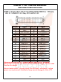
LVDS1: Single /Dual Channel LVDS (18/24/36/48 bit, 1.25mm)
MB: DF-13A-40DP-1.25V / Map: DF13-40DS-1.25C
Pin No.
Signal
Pin No.
Signal
VBL
VBL
1
2
GND
GND
3
4
DISP.ON/OFF
GND
5
6
LCD POWER
LCD POWER
7
8
GND
GND
9
10
Odd 0+
Odd 011
12
Odd 1+
Odd 113
14
Odd 2+
Odd 215
16
Odd 3+
Odd 317
18
Odd CLK+
Odd CLK 19
20
GND
KEY
21
22
23
24
Even 0+
Even 0-.
25
26
Even 1+
Even 127
28
Even 2+
Even 229
30
Even 3+
Even 331
32
Even CLK+
Even CLKLCD POWER
LCD POWER
33
34
GND
GND
35
36
GND
GND
37
38
VBL
VBL
39
40
Please make sure the Pin 1 location before plug-in LCD connector.
Please leave pin 23rd ~ pin 32nd unconnected if the single channel LVDS
function is needed.
Please double check "jumper setting & LCD cable's orientation" before
power-on, any incorrect installation may caused damaged of the LCD.
34
ENDAT-7703 USERS MANUAL
UNICORN COMPUTER CORP.
Appendix C: LIMITED WARRANTY
Standard Two years limited warranty on all our ENDAT series all-in-one
motherboards and embedded board. Products that become defective during the
warranty period shall be repaired, or subject to manufacturer’s option, replaced.
The limited warranty applies to normal proper usage of the hardware and does not
cover products that have been modified or subjected to unusual electrical or
physical stress. Unicorn Computer Corp is not liable to repair or replace defective
goods caused by improper using or use of unauthorized parts. The following
situations will be charged:
1. The products during the warranty but defective caused by improper using or
artificial external pressure and result in the components damages. According to
the damage situation, the manufacturer has the rights to decide to repair or not.
The manufacturer will charge the parts/repair cost and the returning shipping
charge.
2. The products out of warranty will charge the parts/repair cost and the returning
shipping charge as per the repair status.
3. The manufacturer has the rights to decide to repair or not based on the stock of
parts for the products which are phased out of the production.
4. Please e-mail or fax the RMA Service Request Form when have the defective
products.
35
ENDAT-7703 USERS MANUAL
UNICORN COMPUTER CORP.
RMA SERVICE REQUEST FORM
When requesting RMA service, please fill out this “RMA Service Request Form”.
This form needs to be shipped with your returns. Service cannot begin until we
have this information.
RMA NO.:
Company:
Person to Contact:
Phone No:
Purchase Date :
Fax No. :
Applied Date :
Return Shipping Address:
Model No.
Serial No.
Problem Description
Please specify the following when returning the RMA boards:
(1) Hardware Configuration (2) OS or Software (3) Testing Program
___________________
Authorized Signature
36