1
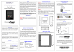
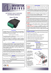
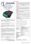
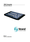
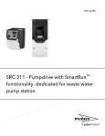
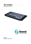
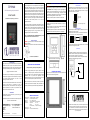
SAFETY OPTIPAD OLED Remote Keypad Option Module User Guide Installation and Operating Instructions Optipad is designed to be used in conjunction with the Optidrive variable speed drive ranges listed. It is intended for professional incorporation into complete equipment or systems. The Optipad can be used to control the operation of the Optidrive ranges ODE-2, ODP2 and ODV-2 (hereafter referred to as Optidrive). The drive must be installed correctly to prevent a safety hazard. The Optidrive uses high voltages and currents, carries a high level of stored electrical energy, and is used to control mechanical plant that may cause injury. Close attention is required to system design and electrical installation to avoid hazards in either normal operation or in the event of equipment malfunction. System design, installation, commissioning and maintenance must be carried out only by personnel who have the necessary training and experience. They must read carefully this safety information and the instructions in this and the Optidrive User Guides and follow all information regarding transport, storage, installation and use, including the specified environmental limitations. ELECTRICAL INSTALLATION MECHANICAL INSTALLATION WARNING When installing the Optipad, all Optidrives should be disconnected and ISOLATED before attempting any work. High voltages are present at the terminals and within the drive for up to 10 minutes after disconnection of the electrical supply. The Optidrives should be installed by qualified electrical persons and in accordance with local and national regulations and codes of practice. Refer to the relevant Optidrive user manual for further details. CAUTION Carefully inspect the Optipad before installation to ensure it is undamaged. Store the Optipad in its box until required. Storage should be clean o o and dry. Temperature range -40 C to +60 C. Install the Optipad on a flat, flame-resistant vibration-free surface. Flammable material should not be placed close to the Optipad. DIMENSIONS Please read the IMPORTANT SAFETY INFORMATION below, and all Warning and Caution boxes within this document. Electrical Interface The Optipad uses a standard RJ45 8-Way connector as its electrical interface, which provides a simple solution for the user to setup their system using a standard RJ45 8-Way data cable. The signal layout of the connector is as follows: NC NC 0V RS485 - / Optibus RS485 + / Optibus +24V NC NC RJ45 Interface Signal Layout Cable Requirements Standard 8-way data cables with plugs are available from your local Invertek Drives stockist on request. If the data cable is made up on site, ensure that the connection pin out is correct: Pin 1 to Pin 1, through Pin 8 to Pin 8. 1 1 SAFETY NOTICES WARNING is given where there is a hazard that could lead to injury or death of personnel. CAUTION is given where there is a hazard that could lead to damage to equipment. CAUTION Incorrect cable connection may damage the drive. Extra care should be taken when using third party cable. System Setup The Optidrive provides the +24V power supply to the Optipad via the RJ45 connection. Once the physical connection has been setup, the system is ready to operate. See picture below: Note: The location of the RJ45 connector on the Optidrive will vary depending on the Optidrive range and model. Dr David Jones, R&D Director DECLARATION All rights reserved. No part of this User Guide may be reproduced or transmitted in any form or by any means, electrical or mechanical including photocopying, recording or by any information storage or retrieval system without permission in writing from the publisher. Copyright Invertek Drives Ltd © 2012 The manufacturer accepts no liability for any consequences resulting from inappropriate, negligent or incorrect installation, or adjustment of the optional operating parameters of the drive or from mismatching of the drive to the motor. The contents of this User Guide are believed to be correct at the time of printing. In the interests of a commitment to a policy of continuous improvement, the manufacturer reserves the right to change the specification of the product or its performance or the contents of the User Guide without notice. IMPORTANT SAFETY INFORMATION Optidrive Safety of machinery, and safety-critical applications The level of integrity offered by the Optipad / Optidrive control functions – for example stop/start, forward/reverse and maximum speed, is not sufficient for use in safety-critical applications without independent means of protection. All applications where malfunction could cause injury or loss of life must be subject to a risk assessment and further protection provided where needed. THROUGH PANEL MOUNT The panel on to which the Optipad is to be mounted should be cut out in accordance with the diagram below. RJ45 Port Within the European Union, all machinery in which this product is used must comply with Directive 98/37/EC, Safety of Machinery. In particular, the electrical equipment should comply with EN60204-1. WARRANTY All Invertek Drives Ltd (IDL) products carry a 2-year warranty, valid from the date of manufacture. Complete Warranty Terms and Conditions are available upon request to your IDL Authorized Distributor. INVERTEK DRIVES LTD Offa’s Dyke Business park Welshpool Powys SY21 8JF UK Tel +44 (0) 1938 556868 Fax +44 (0) 1938 556869 Internet www.invertek.co.uk Part No. 82-OPT-2-OPPAD-IN V 1.00 July 2012 GENERAL SPECIFICATION Compatible Drives: Signal Interface: Supply Input: RS485 signal: Environmental: Protection rating: Max cable length: Optidrive ODE-2, ODP-2, and ODV-2 Standard 8-way RJ45 connector 24V + / - 10%, DC, 30mA Industry standard 2-wire +5V differential Operational: -10 … 50 C Storage: -40 C … 60 C Relative Humidity < 95% (non condensing) IP54 25m / 82.5ft shielded twisted pair Invertek Drives Ltd adopts a policy of continuous improvement and whilst every effort has been made to provide accurate and up to date information, the information contained in this User Guide should be used for guidance purposes only and does not form the part of any contract. USER INTERFACE Navigate Up Start Down Stop Auto Hand NAVIGATE: Used to display real-time information, to access and exit parameter edit mode and to store parameter changes UP: Used to increase speed in real-time mode or to increase parameter values in parameter edit mode DOWN: Used to decrease speed in real-time mode or to decrease parameter values in parameter edit mode RESET / STOP: When drive is in trip mode, this button is used to reset a tripped drive. When operating in Keypad or Hand mode (Optidrive HVAC only), this button is used to stop the drive when enabled and running. START: When operating in Keypad mode or Hand mode (Optidrive HVAC only), the button is used to start a stopped drive or to reverse the direction of rotation if bi-directional keypad mode is enabled (See drive user guide for more information). Hand (Optidrive HVAC Only) : Used to select Hand Mode Operation Auto (Optidrive HVAC Only) : Used to select Auto Mode Operation Allowed System Configurations Depending on the requirement of the application, Optipad can be used in the following different ways: One Optipad with one drive One Optipad with multiple Optidrives (up to 63 max) Two Optipads with one drive EASY STARTUP DRIVE OPERATION To setup the Optidrive communication address By default, the Optipad will try to communicate with the drive that has Address 1 in the network after powering up for the first time. The Optipad will display “Scanning for Drive 01.” after power up, which indicates that the Optipad is searching for the drive with the correct drive address in the network. Once the drive has been found, the message “Load...” will be displayed on the Optipad, which indicates that the Optipad is reading the configuration information from the drive. Usually it will take 1~2 seconds for the Optipad to read this information. After the data has been loaded, the Optipad will display the drive real time status. If the Optipad cannot find the drive in the network, i.e. there is no drive in the network with address equal to 1, the Optipad will display “Select drive address 01”. The user can then adjust the address from 1 to 63 by using the UP or DOWN buttons on the Optipad. Once the address has been changed to a value to match that of a connected drive, the STOP button must be pressed to enable the Optipad to search for the drive again. Working with Multiple Drive Networks When the Optipad is used on networks with multiple drives, the user can change the drive address to set up communication with another drive in the same drive network at anytime. Briefly pressing the STOP and DOWN buttons together results in the message “Select drive address xx” being displayed, where “xx” represents the present drive address. Use the UP or DOWN button to select the desired drive address. After selecting the new address, pressing STOP and DOWN button together again will result in Optipad establishing communications with the drive that has this address. NOTE For detailed parameter listing and functional setup, please refer to the corresponding Optidrive user guide Networks with 2 Optipads connected A maximum of 2 Optipads can be connected within the same drive network to communicate with the same drive or different drives. When using two Optipads simultaneously on a network, the user must change the Optipad Device Number on the second Optipad to ensure correct operation. All Optipad units are set to Device Number 1 by default. To change the Device Number, press the NAVIGATE, STOP and DOWN buttons together. The message “Select OptiPad ID xx” (xx = 01 or 02) will be displayed. The User can then use the UP or DOWN buttons to change the Optipad Device Number to 1 or 2 as required. Press the STOP button to return to normal operation. Note: Once the User has set the Optipad as Device Number 2, Optistore or OptiTools software cannot be used on the same drive network. The Optipad Device Address should only be changed to 2 if 2 Optipad units are connected on a network. An Optipad with Device Number 1 must always be present for the network to function correctly. To change parameter group (ODP-2 & ODV-2 drives only) Ensure that extended parameter group access is enabled. The default extended parameter access code is 101 and this should be entered in P114 to enable the extended parameter group access. Enter parameter edit mode with parameter number PX-XX displayed. Press NAVIGATE button and then simultaneously press and release the UP or DOWN key to change the parameter group number until the required parameter group is displayed. Locking access to the parameters To prevent unauthorised access to the parameters via the Optipad set the following parameter values based on the Optidrive product range in use: ODP-2 or ODV-2 Range: P2-39 = 1 ODE-2 Range: P-39 = 1 Once this parameter has been set, access to parameters via the Optipad will be prevented. The operational information (e.g. speed, current, power etc.) can be still accessed as normal and the drive can still be controlled from the keypad. To unlock parameter access, change parameter listed above back to 0 via the drive keypad directly. Pre-setting target speed in keypad mode Set the following parameter values based on the Optidrive product range in use: ODP-2 or ODV-2 Range: P1-12 = 1 or 2 ODE-2 Range: P-12 = 1 or 2 Setting a value of 1 enables keypad mode with forward direction only, whilst a value of 2 enables keypad mode with forward and reverse rotation (Except Optidrive HVAC). Ensure the following parameters are also set based on the Optidrive product range in use to enable the drive to start from the keypad speed: ODP-2 or ODV-2 Range: P2-37 = 1 or 5 ODE-2 Range: P-31 = 1 or 3 Whilst the drive is stopped, press the STOP key. The value of the digital potentiometer will be displayed, indicating target speed. Use the UP and DOWN keys to select the required target speed. Press the STOP key to return to the real time display showing “Stop”, or the START key to start the drive ramping up to the target speed. To vary the speed in real time in keypad control mode Press the START key. The drive will ramp up to the preset speed set in the digital potentiometer (assuming P2-37 / P-31 = 1). Press UP to increase speed. The drive will run forward, increasing speed until the UP button is released. The maximum speed is the speed set in: ODP-2 or ODV-2 Range: P1-01 ODE-2 Range: P-01 Press DOWN to decrease speed. The drive will decrease speed until the STOP button is released. The minimum speed is the speed set in: ODP-2 or ODV-2 Range: P1-02 ODE-2 Range: P-02 Press the STOP key to stop the drive. The drive will decelerate to stop at the selected deceleration ramp. The display will finally show “Stop” at which point the drive is disabled. Pressing the START key once more results in the drive running back up to the speed at which it was previously running (assuming P2-37 / P-31 = 1). To reverse direction of rotation with P1-12 = 2 (Not Optidrive HVAC) Set the following parameter values based on the Optidrive product range in use to select keypad mode with reverse direction enabled: ODP-2 or ODV-2 Range: P1-12 = 2 ODE-2 Range: P-12 = 2 Press the START key. The drive ramps up to the preset speed as set in the digital potentiometer (assuming P2-37 / P-31 = 1). Press UP or DOWN to increase or decrease the speed. Press the START key again. The motor will reverse its direction of rotation. Press the STOP key to decelerate the motor to standstill. Whenever the drive is started, it will start with a positive speed unless the direction is negated by the digital inputs on the user terminals. REAL TIME OPERATION Two Optipads with multiple Optidrives (up to 63 max) Different drive models can be used on the same Optipad network provided a unique communications address is assigned to each. Note: Cable splitter available from Invertek Drives Ltd on request. Once the communication has been established between the drive and Optipad, the user can operate and monitor the drive by using the control buttons on the front panel of the Optipad. To monitor or change a parameter value Press and hold the NAVIGATE key for more than 1s when the drive is displaying “Stop”. The display changes to the first parameter in the Optidrive parameter menu. Press and release the NAVIGATE key to display the value of the parameter to be edited. Change to the required value using the UP and DOWN keys. Press and release the NAVIGATE key once more to store the change. Press and hold the NAVIGATE key for more than 1s to return to realtime mode. The display shows “Stop” if the drive is stopped or the real-time information (e.g. speed, current or power) if the drive is running. CHANGING THE DISPLAY LANGUAGE Optipad supports multiple languages for the displayed text. To select a different language, simultaneously press the Start and Up keys. A list of available languages will be displayed, which can be selected using the Up and Down keys. To activate the chosen language, press the Navigate key. DRIVE FAULT MESSAGES AND TRIP CODES In the event of a drive fault or trip, the Optipad will display the fault code information from the connected drive. For a full list of the trip codes, and diagnosis and remedy information, please refer to the relevant Optidrive User Guide. OPTIPAD DISPLAY MESSAGES Optipad uses various display messages to indicate different working status. See the following table for more information. Message Explanation Scanning for Drive The Optipad is searching for the drive with xx address ‘xx’ in the network. Load… The Optipad has found the drive in the network and is loading the initialisation information from the drive. SC-OBS The communication link between the Optidrive and Optipad has failed. Select Language Displayed in the language selection screen, with a list of available languages. Press the Navigate key to select a language Select drive address Displayed when selecting the address of xx the Optidrive that the Optipad should try to communicate with. Press the Stop key to select the drive address. Select OptiPad ID Displayed when selecting the Optipad ID (1 or 2) so that two Optipads can be connected to a single drive, or network of multiple drives. TROUBLE SHOOTING Symptom Select drive address xx displayed after ‘SCAN..’ message Display ‘Err-id’ on power up Display ‘Err-id’ during normal operation Display ‘SC-OBS’ Explanation The Optipad failed to successfully communicate with the specified drive address in the network. Check that the RJ45 data cable connection is correct. Check that the drive with address XX is available in the network. If XX > 1 and only one Optipad is connected, then check the Optipad device number, make sure the number is 1. This normally occurs when there are two Optipad units in the same drive network and both of them have the same device number. Check and change the device number of one Optipad. This normally occurs when the user plugs a second Optipad into the drive network. Change the device number of one of the Optipad units. Communication link between the Optipad and Optidrive has failed during operation. Check the electrical connection, and make sure the cable is connected correctly between the Optipad and the drive. Press ‘STOP’ button to enable the Optipad to search for the drive again.