1
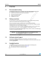
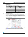
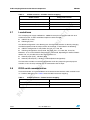
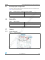
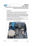
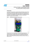
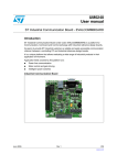
UM1005
User manual
IV
E
STEVAL-IHP002V1: PLM smartplug demonstration board
Introduction
NA
CT
This demonstration board is a smartplug based on the STM32F10x microcontroller, ST7540
PLM, and STPM01 energy metering ICs. The board is a node of a PLM network which
allows the final user to monitor and manage the plugged load energy consumption.
-I
The board has been developed to provide a guideline to build a home/building automation
subsystem for energy management. It is designed to fit the dimension of a standard box for
wall installation and easy integration into home/building electrical plants. The current, power,
energy and other information related to the electrical load connected to the smartplug board
are sent to a PLM data concentrator through the home/building PLM network. The board
includes the following functions shown in the block diagram of Figure 1:
Energy measurement
■
Power line communication up to 4.8 kbps
■
RS232 connectivity
■
Load driver with relay/Triac options
■
Auxiliary relay output
IV
CT
Block diagram
IN
AC
TI
VE
-I
NA
Figure 1.
E
■
January 2011
Doc ID 18006 Rev 1
1/34
www.st.com
Contents
UM1005
Contents
Recommended reading . . . . . . . . . . . . . . . . . . . . . . . . . . . . . . . . . . . . . . . 6
1.2
Safety precautions . . . . . . . . . . . . . . . . . . . . . . . . . . . . . . . . . . . . . . . . . . . 6
1.3
Getting technical support . . . . . . . . . . . . . . . . . . . . . . . . . . . . . . . . . . . . . . 6
1.4
Package checklist . . . . . . . . . . . . . . . . . . . . . . . . . . . . . . . . . . . . . . . . . . . . 6
Microcontroller . . . . . . . . . . . . . . . . . . . . . . . . . . . . . . . . . . . . . . . . . . . . . . 8
2.2
Debug . . . . . . . . . . . . . . . . . . . . . . . . . . . . . . . . . . . . . . . . . . . . . . . . . . . . . 8
2.3
Reset . . . . . . . . . . . . . . . . . . . . . . . . . . . . . . . . . . . . . . . . . . . . . . . . . . . . . 8
2.4
Power supplies . . . . . . . . . . . . . . . . . . . . . . . . . . . . . . . . . . . . . . . . . . . . . . 8
2.5
Power line communication . . . . . . . . . . . . . . . . . . . . . . . . . . . . . . . . . . . . . 8
2.6
Energy measurement . . . . . . . . . . . . . . . . . . . . . . . . . . . . . . . . . . . . . . . . . 9
2.7
Load drivers . . . . . . . . . . . . . . . . . . . . . . . . . . . . . . . . . . . . . . . . . . . . . . . 10
2.8
RS32 serial communication . . . . . . . . . . . . . . . . . . . . . . . . . . . . . . . . . . . 10
2.9
General purpose configuration . . . . . . . . . . . . . . . . . . . . . . . . . . . . . . . . . 11
2.10
Status LEDs . . . . . . . . . . . . . . . . . . . . . . . . . . . . . . . . . . . . . . . . . . . . . . . 11
2.11
Jumpers . . . . . . . . . . . . . . . . . . . . . . . . . . . . . . . . . . . . . . . . . . . . . . . . . . 11
E
IV
CT
NA
2.11.1
Jumper placement . . . . . . . . . . . . . . . . . . . . . . . . . . . . . . . . . . . . . . . . . 11
2.11.2
Jumper positions . . . . . . . . . . . . . . . . . . . . . . . . . . . . . . . . . . . . . . . . . . 12
2.11.3
Jumper description and default value . . . . . . . . . . . . . . . . . . . . . . . . . . 12
Pushbutton description . . . . . . . . . . . . . . . . . . . . . . . . . . . . . . . . . . . . . . . 13
Connector description . . . . . . . . . . . . . . . . . . . . . . . . . . . . . . . . . . . . . . . 13
Connectors . . . . . . . . . . . . . . . . . . . . . . . . . . . . . . . . . . . . . . . . . . . . . . . 14
STM32 JTAG connector . . . . . . . . . . . . . . . . . . . . . . . . . . . . . . . . . . . . . . 14
IN
AC
3.1
3.2
2/34
-I
2.1
2.13
4
NA
CT
PLM smartplug demonstration board components . . . . . . . . . . . . . . . . 8
2.12
3
IV
E
1.1
-I
2
Overview . . . . . . . . . . . . . . . . . . . . . . . . . . . . . . . . . . . . . . . . . . . . . . . . . . 6
TI
VE
1
Energy meter IC calibration connector . . . . . . . . . . . . . . . . . . . . . . . . . . . 14
Board configuration . . . . . . . . . . . . . . . . . . . . . . . . . . . . . . . . . . . . . . . . 15
4.1
Boot . . . . . . . . . . . . . . . . . . . . . . . . . . . . . . . . . . . . . . . . . . . . . . . . . . . . . 15
4.2
STPM01 calibration configuration . . . . . . . . . . . . . . . . . . . . . . . . . . . . . . 15
4.3
STPM01 data line configuration . . . . . . . . . . . . . . . . . . . . . . . . . . . . . . . . 15
Doc ID 18006 Rev 1
UM1005
Contents
Bill of material . . . . . . . . . . . . . . . . . . . . . . . . . . . . . . . . . . . . . . . . . . . . . 16
6
Schematics . . . . . . . . . . . . . . . . . . . . . . . . . . . . . . . . . . . . . . . . . . . . . . . 26
7
Revision history . . . . . . . . . . . . . . . . . . . . . . . . . . . . . . . . . . . . . . . . . . . 33
IN
AC
TI
VE
-I
NA
CT
IV
E
-I
NA
CT
IV
E
5
Doc ID 18006 Rev 1
3/34
List of tables
UM1005
List of tables
NA
CT
IV
E
STM32 resources – ST7540 function mapping . . . . . . . . . . . . . . . . . . . . . . . . . . . . . . . . . . 9
STM32 resources – STPM01 function mapping . . . . . . . . . . . . . . . . . . . . . . . . . . . . . . . . . 10
STM32 resources – RS232 function mapping . . . . . . . . . . . . . . . . . . . . . . . . . . . . . . . . . . 10
STM32 resources – configuration jumpers mapping . . . . . . . . . . . . . . . . . . . . . . . . . . . . . 11
LED description . . . . . . . . . . . . . . . . . . . . . . . . . . . . . . . . . . . . . . . . . . . . . . . . . . . . . . . . . 11
Jumper description . . . . . . . . . . . . . . . . . . . . . . . . . . . . . . . . . . . . . . . . . . . . . . . . . . . . . . . 12
Pushbutton description . . . . . . . . . . . . . . . . . . . . . . . . . . . . . . . . . . . . . . . . . . . . . . . . . . . . 13
Connector description . . . . . . . . . . . . . . . . . . . . . . . . . . . . . . . . . . . . . . . . . . . . . . . . . . . . . 13
STPM01 calibration connector description . . . . . . . . . . . . . . . . . . . . . . . . . . . . . . . . . . . . . 14
Boot modes. . . . . . . . . . . . . . . . . . . . . . . . . . . . . . . . . . . . . . . . . . . . . . . . . . . . . . . . . . . . . 15
BOM list . . . . . . . . . . . . . . . . . . . . . . . . . . . . . . . . . . . . . . . . . . . . . . . . . . . . . . . . . . . . . . . 16
Document revision history . . . . . . . . . . . . . . . . . . . . . . . . . . . . . . . . . . . . . . . . . . . . . . . . . 33
IN
AC
TI
VE
-I
NA
CT
IV
E
-I
Table 1.
Table 2.
Table 3.
Table 4.
Table 5.
Table 6.
Table 7.
Table 8.
Table 9.
Table 10.
Table 11.
Table 12.
4/34
Doc ID 18006 Rev 1
UM1005
List of figures
List of figures
NA
CT
IV
E
Block diagram . . . . . . . . . . . . . . . . . . . . . . . . . . . . . . . . . . . . . . . . . . . . . . . . . . . . . . . . . . . . 1
PLM smartplug board . . . . . . . . . . . . . . . . . . . . . . . . . . . . . . . . . . . . . . . . . . . . . . . . . . . . . . 7
Wiring diagram . . . . . . . . . . . . . . . . . . . . . . . . . . . . . . . . . . . . . . . . . . . . . . . . . . . . . . . . . . . 9
Jumper placement . . . . . . . . . . . . . . . . . . . . . . . . . . . . . . . . . . . . . . . . . . . . . . . . . . . . . . . 11
Jumper positions. . . . . . . . . . . . . . . . . . . . . . . . . . . . . . . . . . . . . . . . . . . . . . . . . . . . . . . . . 12
Auto-calibration mode connection diagram . . . . . . . . . . . . . . . . . . . . . . . . . . . . . . . . . . . . 13
STM32 JTAG connector . . . . . . . . . . . . . . . . . . . . . . . . . . . . . . . . . . . . . . . . . . . . . . . . . . . 14
STPM01 calibration connector . . . . . . . . . . . . . . . . . . . . . . . . . . . . . . . . . . . . . . . . . . . . . . 14
Top page. . . . . . . . . . . . . . . . . . . . . . . . . . . . . . . . . . . . . . . . . . . . . . . . . . . . . . . . . . . . . . . 26
RS232 communication section . . . . . . . . . . . . . . . . . . . . . . . . . . . . . . . . . . . . . . . . . . . . . . 27
Power supply section . . . . . . . . . . . . . . . . . . . . . . . . . . . . . . . . . . . . . . . . . . . . . . . . . . . . . 28
Power line communication section . . . . . . . . . . . . . . . . . . . . . . . . . . . . . . . . . . . . . . . . . . . 29
MCU section . . . . . . . . . . . . . . . . . . . . . . . . . . . . . . . . . . . . . . . . . . . . . . . . . . . . . . . . . . . . 30
Energy meter . . . . . . . . . . . . . . . . . . . . . . . . . . . . . . . . . . . . . . . . . . . . . . . . . . . . . . . . . . . 31
Output drivers . . . . . . . . . . . . . . . . . . . . . . . . . . . . . . . . . . . . . . . . . . . . . . . . . . . . . . . . . . . 32
IN
AC
TI
VE
-I
NA
CT
IV
E
-I
Figure 1.
Figure 2.
Figure 3.
Figure 4.
Figure 5.
Figure 6.
Figure 7.
Figure 8.
Figure 9.
Figure 10.
Figure 11.
Figure 12.
Figure 13.
Figure 14.
Figure 15.
Doc ID 18006 Rev 1
5/34
Overview
UM1005
1
Overview
1.1
Recommended reading
ST devices datasheets referenced in this document
●
Third party device datasheets
●
AN3287 application notes
●
UM1006 user manual.
NA
CT
1.2
●
IV
E
This document describes how to configure and use the PLM smartplug demonstration
board. Additional information can be found in the following documents:
Safety precautions
The board must be used only by expert technicians. Due to the high voltage (220 Vac)
special care should be taken with regard to human safety.
-I
There is no protection against accidental human contact with high voltages.
E
After disconnection of the board from the mains, none of the live parts should be touched
immediately because of the energized capacitors.
IV
It is mandatory to use a mains insulation transformer to perform any tests on the board in
which test instruments such as spectrum analyzers or oscilloscopes are used.
NA
Getting technical support
TI
VE
1.3
ST assumes no responsibility for any consequences which
may result from the improper use of this tool
-I
Warning:
CT
Do not connect any oscilloscope probes to high voltage sections in order to avoid damaging
instruments and demonstration tools.
Technical assistance is provided free to all customers. For technical assistance,
documentation, upgrades and information about products and services, please refer to your
local ST distributor/office.
Package checklist
IN
AC
1.4
The PLM smartplug demonstration board package includes the following items:
6/34
●
The PLM smartplug demonstration board (Figure 2)
●
A CD-ROM with software and documentation
Doc ID 18006 Rev 1
UM1005
Overview
PLM smartplug board
IN
AC
TI
VE
-I
NA
CT
IV
E
-I
NA
CT
IV
E
Figure 2.
Doc ID 18006 Rev 1
7/34
PLM smartplug demonstration board components
UM1005
2
PLM smartplug demonstration board components
2.1
Microcontroller
IV
E
The system is managed by the STM32F103CB microcontroller. It is based on the 32-bit
ARM Cortex -M3 core with 72 Mhz maximum frequency, 128 KB flash and 20 KB SRAM
embedded memories. For further details please refer to the STM32F103x4 STM32F103x6
and the STM32F103x8 STM32F103xB datasheets.
2.2
NA
CT
The microcontroller is driven by an external 8 MHz crystal for the high speed main clock.
Some jumpers are connected to the microcontroller GPIOs in order to allow firmware
configuration.
Debug
Reset
IV
2.3
E
-I
Software debug is via a standard 20-pin JTAG connection. The JTAG connector is not
insulated, so for debugging use the JTAG opto-insulation board (order code: AIJTAG/OPTO-1/A), a battery supplied notebook, or supply the board through an insulated AC
source.
The Reset sources are:
●
Pushbutton reset
●
JTAG reset from an in-circuit emulator
Power supplies
CT
Power on reset
NA
2.4
●
-I
The board is powered directly by the mains. It includes an insulated extended range power
supply and both 50 Hz and 60 Hz frequencies.
2.5
TI
VE
The power supply consists of an SPAC265-3W AC/DC module; it provides 12 Vdc with
250 mA maximum current. The 5 Vdc and the 3.3 Vdc are generated by an LD1117XX50
and an LD1117ADT33TR linear regulator starting from 12 Vdc.
Power line communication
IN
AC
The board allows digital data communication through power line modulation using the
ST7540 power line modem. For more details about the modem please refer to the ST7540
datasheet. The ST7580 supports B-FSK modulation up to 4800 bps; it is compliant with
CENELEC band A, B, and C, supports preamble and unique word reception
synchronization, and has a 500 mArms output current with 12 Vpp single-ended thanks to
its integrated amplifier. The modem is coupled with the mains by a non-insulated topology
using a capacitor. The ST7540 is managed by an SPI and two control lines: the REG_DATA
line, which is used to select the access to the configuration register or to the data, and the
RxTx line which is used to select the reception or transmission mode. Moreover, the ST7540
provides information about the preamble/unique-word detection (CD/PD) and the carrier
8/34
Doc ID 18006 Rev 1
UM1005
PLM smartplug demonstration board components
sensing (BU) by two digital outputs. Table 1 shows the MCU resources mapping used for
ST7540 management:
STM32 resources – ST7540 function mapping
ST7540 function
PA1
REG_DATA
PA2
CD/PD
PA3
BU
PA4
RxTx
IV
E
STM32 resource
NA
CT
Table 1.
SPI1-SCK (PA5)
SCK
SPI1-MISO (PA6)
TXD
SPI1-MOSI (PA7)
-I
Energy measurement
CT
Wiring diagram
TI
VE
-I
NA
Figure 3.
IV
E
The energy meter section is based on the STPM01 programmable single-phase energy
meter IC. The STPM01 supports 50÷60 Hz - IEC62052-11, IEC62053-2X specifications with
less than 0.1 % error. For further details please refer to the STPM01 datasheet. The current
sensing is done by the current transformer; the STPM01 also measures the mains voltage.
The image in Figure 3 shows the wiring diagram.
IN
AC
2.6
RXD
The STPM01 is controlled by the MCU with an SPI communication bus and digital control
line. Table 2 shows the MCU resources mapping for energy meter IC management:
Doc ID 18006 Rev 1
9/34
PLM smartplug demonstration board components
Table 2.
STM32 resources – STPM01 function mapping
Energy meter function
PA11
SYN
SPI2-MOSI/MISO (PB15/PB14)
SDA
SPI2-SCK (PB13)
SCL
PB12
SCS
IV
E
STM32 resource
NA
CT
2.7
UM1005
Load drivers
The smartplug can supply 110/230 Vac - 50/60 Hz mono-phase resistive load with 16 A
maximum current. It offers two different options to drive the load:
●
ON/OFF by a relay
●
Dimming by Triac
-I
The default configuration is the dimming one. Configuration selection is done by changing
the fitted component into the output section of the board, as described in the following:
ON/OFF configuration: fit only R104, Q4, D12, k1, C116, R3
●
Dimming configuration: fit only R104, Q4, R101, D11, C1, R102, Q3, C116, R3
E
●
IV
Moreover, as far as the ON/OFF configuration is concerned, depending on whether R103 is
fitted or not, it is possible to have the output contacts as:
Normally open (N.O.), if R103 is fitted
●
Normally closed (N.C.), if R103 is not fitted (default configuration)
CT
●
RS32 serial communication
-I
2.8
NA
The board also includes an auxiliary independent 16 A relay output for general purpose
function, in fact, the relay contacts are not connected to the AC input.
TI
VE
The board includes an insulated RS232 serial communication interface which could be used
as a runtime debugging port. Table 3 shows the MCU resources mapping:
STM32 resources – RS232 function mapping
STM32 resource
Serial communication function
USART1-TX (PA9)
RS232-TX
USART1-RX (PA10)
RS232-RX
IN
AC
Table 3.
10/34
Doc ID 18006 Rev 1
UM1005
2.9
PLM smartplug demonstration board components
General purpose configuration
The boards support three general purpose configuration jumpers for the STM32 firmware,
Table 4 shows the resource mapping:
2.10
STM32 resources – configuration jumpers mapping
Jumpers
PB5
CONF0
PB6
CONF1
PB7
CONF2
IV
E
STM32 resource
NA
CT
Table 4.
Status LEDs
Table 5.
LED description
-I
LED
DL1
E
D1
2.11.1
Jumper placement
Energy measurement
Jumper placement
IN
AC
TI
VE
-I
Figure 4.
General purpose bi-color
CT
Jumpers
5 V power supply
NA
2.11
IV
DL2
Description
Doc ID 18006 Rev 1
11/34
PLM smartplug demonstration board components
2.11.2
UM1005
Jumper positions
Figure 5.
Jumper positions
.OTFITTED
$ONOTFIT
&ITTED
!-V
Jumper
Default
SW2, SW5
Boot option
- Fitted (1-2): boot option bit 0
- Fitted (2-3): boot option bit 1
Fitted (1-2)
NA
CT
Description
General purpose configuration
bit
- Fitted (1-2): configuration bit 1
- Fitted (2-3): configuration bit 0
Fitted (2-3)
STPM01 calibration mode
- Fitted (1-2): normal mode
- Fitted (2-3): calibration mode
Fitted (1-2)
Energy meter data line option
- Fitted (1-2): data line
connected to SPI2-MISO
- Fitted (2-3): data line
connected to SPI2-MOSI
Fitted (1-2)
-I
SW3, SW6, SW7,
TI
VE
SW8, SW10, SW11, SW12
IN
AC
SW9
12/34
.OTFITTED
IV
Jumper description
E
Jumper description and default value
Table 6.
&ITTED
&ITTED
.OTFITTED
2.11.3
IV
E
NA
CT
-I
Doc ID 18006 Rev 1
UM1005
Pushbutton description
Description
S3
General purpose button
S4
General purpose button
SW4
STM32 reset button
IV
E
Switch
Connector description
Auto-calibration mode connection diagram
Table 8.
Connector description
NA
CT
IV
E
-I
Figure 6.
TI
VE
Connector
IN
AC
2.13
Pushbutton description
NA
CT
Table 7.
-I
2.12
PLM smartplug demonstration board components
Description
J6
STPM01 calibration connector
J2
JTAG connector for STM32
CN1
RS232 connector
J9
220 VAC IN/OUT
W3 W1
AC LOAD connector
J7
220 VAC IN/OUT
J4
Auxiliary relay output
Doc ID 18006 Rev 1
13/34
Connectors
UM1005
3
Connectors
3.1
STM32 JTAG connector
STM32 JTAG connector
$EBUG*4!'PORT
!-V
-I
E
Energy meter IC calibration connector
Figure 8.
STPM01 calibration connector
Table 9.
STPM01 calibration connector description
Description
Pin
Description
1
VOTP
6
SCLK_CAL
2
SBG
7
LED
3
GND
8
SYN_CAL
4
SDA_CAL
9
SBG
5
SCS_CAL
10
Not connected
IN
AC
TI
VE
Pin
-I
NA
CT
IV
3.2
NA
CT
IV
E
Figure 7.
14/34
Doc ID 18006 Rev 1
UM1005
Board configuration
4
Board configuration
4.1
Boot
Table 10.
Boot modes
Boot mode selection pins
Aliasing
BOOT0
x
0
Main Flash memory
Main Flash memory is
selected as boot space
0
1
System memory
System memory is
selected as boot space
1
1
Embedded SRAM
Embedded SRAM is
selected as boot space
E
-I
BOOT1
STPM01 calibration configuration
IV
4.2
NA
CT
Boot mode
IV
E
The board allows configuration of the boot options of the STM32 by setting the jumpers
SW5 and SW2: SW2 drives BOOT0 and SW5 drives BOOT1.
NA
STPM01 data line configuration
TI
VE
-I
It is possible to configure if using the SPI2 MOSI or SPI2 MISO as the energy meter data
line, setting SW9 according to Table 6.
IN
AC
4.3
CT
To calibrate the STPM01, the SW8, SW10, SW11, and SW12 must be set according to
Table 6. When these switches are set in calibration mode, the STPM01 can be driven by an
external programmer using the connector J6.
Doc ID 18006 Rev 1
15/34
Reference
Part /
value
Tolerance
%
Voltage
current
IV
E
BOM list
Technology
information
Watt
Packagefoot-print
9-way r/a PCB D
plug, US footprint Through hole
8.1mm
2.2 µF
+/-10 %
50 V
Ceramic
capacitor X7R
C5,C6
22 pF
+/-10 %
50 V
Ceramic
capacitor X7R
C7
470 nF
+/-10 %
50 V
Ceramic
capacitor X7R
C11, C12
33 pF
+/-10 %
50 V
Ceramic
capacitor X7R
C14, C27,
C103
10 nF
±10 %
50 V
Ceramic
capacitorX7R
SMD 0603
C114,
C115
10 nF
+/-10 %
50 V
Ceramic
capacitor X7R
SMD 0805
C15, C17,
C24
10 µF
±10 %
16 V
Ceramic
capacitorX7R
C16, C18,
C25
100 nF
±10 %
50 V
C22
10 µF
±10 %
C116
47 nF
+/-10 %
C101
10 µF
10 %
-I
C1
Manufacturer
Any
Manufacturer
code
RS/Distrelec/
other
code
More
info
RS code: 1602590
IV
E
SMD 0805
SMD 0805
NA
CT
SMD 0805
SMD 0805
GRM188R71H10 RS code: 2043KA01D
0779
SMD 1206
Kemet
C1206C106K4PA RS code: 648C7800
0755
Ceramic
capacitorX7R
SMD 0603
muRata
GRM188R71H10 RS code: 6244KA93D
2480
10 V
Ceramic
capacitor X5R
SMD 0805
muRata
GRM21BR61A10 RS code: 1066KE19L
846
300 V
X2 Capacitor
Through
Hole
Any
RS code: 4419600
10 V
Tantalium
capacitor
SMD
Any
RS code: 4647619
CT
IV
E
-I
muRata
Bill of material
16/34
PORT 0
IN
A
Doc ID 18006 Rev 1
CN1
CT
Table 11.
NA
Bill of material
UM1005
5
IV
E
BOM list (continued)
Manufacturer
±20 %
300 V
X2 Capacitor
Through
Hole
Any
C26
6.8 nF
±5 %
50 V
Ceramic
capacitor COG
SMD 1206
C30
15 pF
±5 %
50 V
Ceramic
capacitor COG
SMD 0402
C31
22 pF
±5 %
50 V
Ceramic
capacitor COG
SMD 0402
C32
270 pF
±5 %
50 V
Ceramic
capacitor COG
C21,C33
100 pF
±5 %
50 V
Ceramic
capacitor COG
C68, C69,
C70, C71,
C102,
C105,
C106,
C107, C93,
C97, C98,
C99, C100,
C104,
C109,
C110,
C111,
C112,
C113
100 nF
+/-10 %
50 V
Ceramic
capacitor X7R
SMD 0805
C91, C92
47 nF
+/-10 %
50 V
Ceramic
capacitor X7R
SMD 0805
C94, C95
10 µF
+/-20 %
50 V
Electrolytic
capacitor
SMD
NA
68 nF
NA
-I
CT
IV
E
Doc ID 18006 Rev 1
IN
A
Manufacturer
code
RS/Distrelec/
other
code
Distrelec
code: 821885
muRata
GRM3195C1H68 RS code: 6242JA01D
2597
muRata
GRM1555C1H15 RS code: 6240JZ01D
2935
muRata
GRM1555C1H22 RS code: 6240JZ01D
2187
SMD 0603
Kemet
C0603C271J5GA RS code: 147C7867
207
SMD 0603
muRata
GRM1885C1H10 RS code: 6531JA01D
0327
-I
C23
CT
Packagefoot-print
Any
RS code: 5369859
More
info
UM1005
Technology
information
Watt
E
Voltage
current
IV
Tolerance
%
CT
Part /
value
Reference
Bill of material
17/34
Table 11.
+/-10 %
50 V
Ceramic
capacitor X7R
SMD 0805
C117,C118
470 µF
+/-20 %
25 V
Electrolytic
capacitor low
ESR
Through hole
C96, C119
47 µF
+/-20 %
25 V
Electrolytic
capacitor
SMD
C120
33 nF
+/-10 %
275 V
X2 capacitor
Through hole
DL1
Red
Chip LED
DL2
Blue
Chip LED
D1
Bi-color
LED red
/ green
D6, D12,
D13
LL4148
D8, D10
BAT54S
D9
SM6T15
CA
D11
STPS14
0U
F1
1A
F2
15 A
Manufacturer
code
RS/Distrelec/
other
code
Any
Distrelec
code: 801846
Any
RS code: 565712
Any
RS code: 118148
Any
Distrele code:
250154
SMD 0805
Any
Distrele code:
250159
LED Bi-Red,
Green
SMD
Any
RS code: 419053
Switching diode_
SOD-80
Any
Distrelec
code: 601496
Small signal
Schottky diodes
SOT-23
STMicroelectronics
BAT54SFILM
Transil
SMB
STMicroelectronics
SM6T15CA
Power Schottky
rectifier
SMB
STMicroelectronics
STPS140U
TR5 anti-surge
submin PCB T
fuse
Through hole
Any
NA
-I
CT
IV
E
18/34
IN
A
Doc ID 18006 Rev 1
250
V/15 A
CT
1 nF
-I
C108
Manufacturer
NA
Packagefoot-print
SMD 0805
Min fuse 15 A
5x20 mm
RS code: 6110658
RS code: 5414599
More
info
Bill of material
Technology
information
Watt
E
Voltage
current
IV
Tolerance
%
CT
Part /
value
Reference
IV
E
BOM list (continued)
UM1005
Table 11.
IV
E
Tolerance
%
Voltage
current
Watt
Packagefoot-print
Manufacturer
Socket for F2
Through hole
Wickmann
Manufacturer
code
RS/Distrelec/
other
code
652
Distrelec
code: 273260
Wickmann
655
Distrelec
code: 273262
STMicroelectronics
ST3232EBDR
Cap for socket
IC1
ST3232
EBDR
RS-232 drivers
and receivers
SO-16
IC2
LD1117
DT50TR
Low drop fixed
and adjustable
positive voltage
regulators
DPAK
STMicroelectronics
LD1117DT50TR
IC3
LD1117
ADT33T
R
Low drop fixed
and adjustable
positive voltage
regulators
DPAK
STMicroelectronics
LD1117ADT33T
R
JP4, JP5
Close
Do not fit
Do not fit
Do not fit
Do not fit
J1
Peak
meter
connect
or
5-way single-row
strip line
connector (male
connector) 2,54
mm pitch
Vertical
through hole
Any
RS code:4958470
4-way single-row
strip line
connector (male
connector) 2,54
mm pitch
Vertical
through hole
Any
RS code:4958470
20-way IDC low
profile boxed
header 2,54 mm
pitch
Vertical
through hole
Any
RS code:
461770
J2
Rfid
reader
JTAG
E
CT
Do not fit
-I
NA
More
info
UM1005
CT
IV
E
J8
-I
Cap for
socket
IN
A
Doc ID 18006 Rev 1
Cap for
socket
IV
Socket for
F2
Technology
information
CT
Part /
value
NA
Reference
BOM list (continued)
Bill of material
19/34
Table 11.
IV
E
Tolerance
%
Voltage
current
Watt
Technology
information
Packagefoot-print
Vertical
through hole
CON3
3-way screw
terminal block
5.08 mm pitch
J6
CAL
CON
10-way IDC low
profile boxed
header 2.54 mm
pitch
Vertical
through hole
J7, J9
CON2
2-way screw
terminal block
7.5 mm pitch
L1
2x10
mH
L5
22 µH
±10 %
2.1 A
L6
220 µH
±10 %
240 mA
L7,L9
1 mH
±10 %
L8
10 µH
±10 %
Q1, Q2
BC857B
code
RS/Distrelec/
other
code
Any
RS code:4958470
Through hole
Any
RS code:1895865
E
J4
Manufacturer
Any
RS code: 461742
-I
IV
CT
Phoenix Contact
NA
RS code: 5487301
Through hole
Line filter
Through hole
Any
Smd inductor
SMD
EPCOS
B82464A4223K
RS code: 4960445
Smd inductor
SMD
EPCOS
B82462A4224K
RS code: 4958048
330 mA
Smd inductor
SMD
EPCOS
B82464A4105K
RS code: 4960530
1A
Smd inductor
SMD
EPCOS
B82442H1103K
RS code: 4961268
PNP transistor
SOT23
Any
20/34
CT
IV
E
-I
0.5 A
1988105
More
info
Distrelec
code: 351276
RS code: 4452051
Bill of material
CON2
IN
A
Doc ID 18006 Rev 1
J3
2-way single-row
strip line
connector (male
connector) 2.54
mm pitch
Manufacturer
CT
Part /
value
NA
Reference
BOM list (continued)
UM1005
Table 11.
IV
E
Voltage
current
Watt
Packagefoot-print
Manufacturer
D2PAK
ST Microelectronics
T2035H-6G-TR
ST Microelectronics
2STR1215
Q4, Q5
2STR12
15
Low voltage fastswitching NPN
power transistor
SOT-23
R3
1 kΩ
+/-5 %
1/2 W
Resistor
Axial through
hole
R6
1.1 kΩ
+/-1 %
0.1 W
Resistor
SMD 0603
R7
47 kΩ
+/-1 %
0.1 W
Resistor
R8
15 kΩ
+/-1 %
0.1 W
Resistor
R9
4.7 kΩ
+/-1 %
0.1 W
Resistor
SMD 0603
R88, R108,
R109
4.7 kΩ
+/-5 %
1/8 W
Resistor
SMD 0805
R10
13 kΩ
+/-1 %
0.1 W
Resistor
SMD 0603
R12
1 kΩ
+/-1 %
0.1 W
Resistor
SMD 0603
R62, R68,
R104,
R106
1 kΩ
+/-5 %
1/8 W
R13
2.7 kΩ
+/-1 %
R14
1.8 kΩ
+/-1 %
R17
470 Ω
+/-1 %
R19
2.4 kΩ
+/-1 %
R85, R86,
R87
2.4 kΩ
+/-5 %
R20
56 kΩ
code
RS/Distrelec/
other
code
More
info
IV
E
-I
T2035H
SMD 0603
-I
NA
CT
SMD 0603
SMD 0805
0.1 W
Resistor
SMD 0603
0.1 W
Resistor
SMD 0603
0.1 W
Resistor
SMD 0603
0.1 W
Resistor
SMD 0603
1/8 W
Resistor
SMD 0805
0.1 W
Resistor
SMD 0603
UM1005
Resistor
CT
IV
E
Doc ID 18006 Rev 1
Q3
High
temperature 20 A
Snubberless™
Triacs
+/-1 %
Manufacturer
Technology
information
CT
Tolerance
%
NA
Part /
value
IN
A
Reference
BOM list (continued)
Bill of material
21/34
Table 11.
IV
E
R21, R96,
R97
261 kΩ
+/-1 %
R59, R60
0
R61, R89
Voltage
current
Packagefoot-print
1/4 W
Resistor
SMD 1206
+/-5 %
1/8 W
Resistor
SMD 0805
560 Ω
+/-5 %
1/8 W
Resistor
SMD 0805
R63, R64,
R65, R66,
R71, R72,
R73, R74,
R76, R77,
R80, R81,
R82, R83,
R84
10 kΩ
+/-5 %
1/8 W
Resistor
SMD 0805
R67
(Not
mounted
)
+/-5 %
1/8 W
Resistor
SMD 0805
R69, R70
82 Ω
+/-5 %
1/4 W
Resistor
SMD 1206
R75
1 MΩ
+/-5 %
1/8 W
Resistor
SMD 0805
R91, R92
6.8 Ω
+/-1 %
1/4 W
Resistor
SMD 1206
R94
2 MΩ
+/-1 %
1/8 W
Resistor
SMD 0805
R98
475 Ω
+/-1 %
1/4 W
Resistor
SMD 1206
R99
43 kΩ
+/-1 %
1/8 W
Resistor
SMD 0805
R100
100 Ω
+/-1 %
1/8 W
Resistor
SMD 0805
R101
1 kΩ
+/-1 %
1/4 W
Resistor
SMD 1210
R102
22 Ω
+/-1 %
1/4 W
Resistor
SMD 1210
R103,
R105
1 kΩ (do
not fit)
+/-1 %
1/4 W
Resistor
SMD 1210
R90, R93
1 kΩ
+/-1 %
1/8 W
Resistor
SMD 0805
Watt
Manufacturer
CT
Tolerance
%
Manufacturer
code
RS/Distrelec/
other
code
More
info
CT
-I
CT
IV
E
Bill of material
22/34
IN
A
Doc ID 18006 Rev 1
IV
E
-I
Part /
value
Reference
NA
Technology
information
NA
BOM list (continued)
UM1005
Table 11.
+/-1 %
1/8 W
Resistor
SMD 0805
R107
10
5%
1W
Fuse resistor
Axial through
hole
RV1
S14K51
0
10 %
Disk-shaped
metal-oxide
varistors
Through hole
BOOT_0
3-way single-row
strip line
connector (male
connector) 2.54
mm pitch
Vertical
through hole
SW3
CONF3
3-way single-row
strip line
connector (male
connector) 2.54
mm pitch
SW4
Rst
BOOT_1
SW6
CONF0
Any
EPCOS
Manufacturer
code
RS/Distrelec/
other
code
More
info
RS code: 2140879
B72214S0511K1
Distrelec
01
code: 730933
Any
RS code:4958470
Single
strip
line 3
poles
Vertical
through hole
Any
RS code:4958470
Single
strip
line 3
poles
Surface mount
tactile switch
SMD
Any
RS code
183701
3-way single-row
strip line
connector (male
connector) 2.54
mm pitch
Vertical
through hole
Any
RS code:4958470
Single
strip
line 3
poles
3-way single-row
strip line
connector (male
connector) 2.54
mm pitch
Vertical
through hole
Any
RS code:4958470
Single
strip
line 3
poles
UM1005
NA
-I
CT
IV
E
Doc ID 18006 Rev 1
SW5
IN
A
SW2
510 VAC
CT
0
Manufacturer
NA
Packagefoot-print
-I
Technology
information
Watt
E
R95
Voltage
current
IV
Tolerance
%
CT
Part /
value
Reference
IV
E
BOM list (continued)
Bill of material
23/34
Table 11.
Vertical
through hole
SW8, SW9,
Calibrati
SW10,
on
SW11,
settings
SW12
3-way single-row
strip line
connector (male
connector) 2.54
mm pitch
Vertical
through hole
U1
SPAC26
5-3W
U3
ST7540
code
SMD
RS/Distrelec/
other
code
More
info
Any
RS code:4958470
Single
strip
line 3
poles
Any
RS code:4958470
Single
strip
line 3
poles
Any
RS code
183701
E
Current
transfor
mer
IV
T1
Manufacturer
NA
CT
Test
point
Manufacturer
Test point
Test point
Test point
Current
Transformer
Through
Hole
VAC
T60404-E 4622X503
AC-DC switch
mode power
supply
Through hole
ST Microelectronics
SPAC265BC12P
0.30
FSK power line
transceiver
HTSSOP28
ST Microelectronics
ST7540TR
Test point
CT
IV
E
-I
Test point
Bill of material
24/34
TP8,TP9,
TP10,TP11
,TP12,
TP13,TP14
,TP15,
TP16,TP17
,TP18,
TP19,TP20
,TP21,
TP22,TP23
,TP25,
TP26,TP27
Watt
Surface mount
tactile switch
IN
A
Doc ID 18006 Rev 1
SW
push
Voltage
current
CT
CONF1
3-way single-row
strip line
connector (male
connector) 2.54
mm pitch
S3,S4
Tolerance
%
NA
Packagefoot-print
SW7
Part /
value
-I
Technology
information
Reference
IV
E
BOM list (continued)
UM1005
Table 11.
IV
E
Tolerance
%
Voltage
current
Watt
Technology
information
Packagefoot-print
Manufacturer
Traco Power
DC-DC converter
SOIC-14
U10
IL712S1E
Bi-directional
Digi Isolator
MSOP8
U11
STM32F
103CBT
6
Medium-density
performance line
ARM-based 32bit MCU
LQFP48
U12
STPM01
Programmable
single-phase
energy metering
IC with tamper
detection
W1 W3
Load
2-way screw
terminal block
7.5 mm pitch
X1
16 MHz
Y1
8 MHz
k1
16 A 12
Vdc coil
(Do not
fit)
k2
16 A 12
Vdc coil
code
RS code: 5105431
NVE
IL712S-1E
RS code: 418436
ST Microelectronics
STM32F103CBT
6
ST Microelectronics
STPM01FTR
Through hole
Phoenix contact
1988105
16 MHz crystal
SMD
Any
RS code: 5476531
16 MHz crystal
SMD
Any
RS code: 6719242
(Do not fit)
(Do not fit)
(Do not fit)
(Do not fit)
(Do not fit)
OMRON
G2RL-1-E 12DC
RS code: 3650535
More
info
E
IV
TSSOP20
CT
NA
-I
12 V/16
A
code
RS/Distrelec/
other
Low profile
Through hole
SPDTpowerrelay
RS code: 5487301
(Do not
fit)
UM1005
CT
IV
E
(Do not
fit)
Manufacturer
TSM0505S
-I
TSM050
5S
IN
A
Doc ID 18006 Rev 1
U9
CT
Part /
value
NA
Reference
BOM list (continued)
Bill of material
25/34
Table 11.
Schematics
UM1005
IV
E
,
5!24?48
5!24?28
53!24?48
53!24?28
-I
23
#,24
2X$
4X$
34-
0,-?3#+
0,-?28
0,-?48
%!24(
NA
'.$?0,#/.
*
#/.
*
"54(%2#$0$
2X4X
2%'?$!4 !
-I
TI
VE
3+
26
&
!
IN
AC
26/34
0##OMM
NA
CT
42)!#2ELAY
/04?/54?#-$
E
IV
0,-?"5
0,-?#$0$
0,-?2X4X
0,-?2%'$!4 !
CT
340-
340-?39.
340-?3#3
340-?3#+
340-?-)3/
340-?-/3)
-#5
.
39.?-#5
30)?3#3
30)?#,+
30)?-)3/
30)?-/3)
,
%NERGY-EASUREMENT
30! #7
.
,
0OWER3UPPLY
:#2
-#/
/04?#-$
42)!#?#-$
/54?#-$
$IMMER3WITCH
.
:#2
#,+
34
Top page
.
Figure 9.
,
Schematics
0,-
6
!-V
Doc ID 18006 Rev 1
5!24?28
5!24?48
2
2
6
#
N&
6
6O
),3%
'.$
/54
).
6$$
5
6O
.#
.#
'.$
).
/54
6$$
#
N&
#
N&
#
N&
E
IV
6?)3/,
CT
6?)3/,
NA
43-3
6IN
.#
.#
6IN
-I
5
)#
#
#
#
2/54
2/54
4).
4).
#
-I
# N&
# N&
28
34%"$2
2).
2).
4/54
48
NA
CT
4/54
6
6
6?)3/,
6##
'.$
Doc ID 18006 Rev 1
TI
VE
IN
AC
IV
E
48
28
0/24
#.
UM1005
Schematics
Figure 10. RS232 communication section
!-V
27/34
Doc ID 18006 Rev 1
.
,
M(
,
#
N&8
&)4
,
2
7
6/54
30! #7
!#?).
6/54 U(
U&6
#
,
E
U&6
#
IV
U&6
#
CT
6##?6
NA
-I
5
!#?).
TI
VE
6).
-I
#
N&
U&6
#
6
$,
2%$
2
NA
CT
)#
6/54
,$$442
'.$
6).
IV
E
U&6
#
)#
6/54
,$!$442
'.$
28/34
IN
AC
U&6
#
6##?6
Schematics
UM1005
Figure 11. Power supply section
!-V
Doc ID 18006 Rev 1
$IGITAL
'ROUND
#
U&
0! ?).
0! ?).
0! ?/54
4X?/54
#$0$
6SENSE
!NALOG
3IGNAL
'ROUND
6DD
#
N&
40
40
!NALOG
0OWER
'ROUND
40
40
40
40
40
40
40
40
4X$
#
U&
40
40
40
40
6$#
*0
#,/3%
#
N&
6$#
4X?/54
6$#
6DD
6DD
2
K
2
K
6CC
#
N&
#$0$
2%'?$!4!
2
K
#,
2
K
6DD
-#,+
234/
5!2430)
7$
0! ?).
2X$
2X4X
4X$
"54(%2#,24
#
N&
4X?/54
2
K
2
+
34
0! ?/54
4X?/54
0! ?).
2X?).
#,
6SENSE
4%34
4%34
#
U&
$
6CC
2
6$#
6CC
#
N&
,
M(
"!433/4
#
P&
8
-HZ
/3#).
#
P&
,
U(
6CC
6$#
*
0%!+-%4%2#/..%#4/2
36SS
2X?).
$
3-4#!
#
N&8
IV
E
4%34
4%34
NA
CT
,
U(
2
K
#
N&
6CC
4%34
4%34
6$#
2X?).
#,
6SENSE
8
8?/3#).
36SS
4X?/54
0!?).
6CC
6SS
0!?/54
"!433/4
-I
6$#
#$0$
2%'?$!4!
'.$
2X$
2X4X
4X$
"54(%2#,24
6DD
-#,+
234/
5!2430)
7$
0!?).
6SENSE
0! ?/54
2X?).
2
K
#
P&
$
0!
E
#
P&
5
0! ?).
0! ?).
2
K
#
P&
#
P&
IV
CT
#
P&
2
K
6##?6
NA
-I
'.$?0,-
#
U&
TI
VE
40
40
40
40
40
*0
#,/3%
2X?).
6DD
234/
#,
7$
#,24
2X4X
2X$
IN
AC
6CC
"54(%2-
5!2430)
-#,+
2%'?$!4!
6$#
4%340!$ 3
.
,
UM1005
Schematics
Figure 12. Power line communication section
!-V
29/34
Schematics
UM1005
Figure 13. MCU section
6
6
2
K
"#"
1
2
2
2
2
2
+
+
+
+
./4-/5.4%$
*4.4234
"#"
1
*44-3
2
2
*44#+
*44$/
6
2%3%4
2
+
2%3%4
9
6
-(Z
"//4?
0"
0"
0"
*4.4234
*44$/
*44$)
*44#+
6$$
633
0"
0"
"//4
0"
0"
0"
0"
0"
0! 0! #
N&
*44-3
53!24?28
53!24?48
30)?-/3)
30)?-)3/
30)?3#+
0! 0! 0! 0! 0! 0"
0"
0"
0"
0"
633
6$$
#
P&
6$$
633
0!
0!
0!
0!
0!
0!
0"
0"
0"
0"
6"!4
0#4!-024#
0#
0#
0$/3#).
0$/3#/54
.234
633!
6$$!
0!7+50
0!
0!
#
N&
0! 0! 30)?3#+
30)?-)3/
30)?-/3)
4)-?#(
4)-?#(
"//4?
)#?3#,
)#?3$!
#
P&
6
6
#
N&
E
2
37 2ST
3 4- &# " 4 0! 0! 0! 0! 30)?3#+
30)?-/3)
30)?-)3/
CT
:#2
42)!#?#-$
6
2
K
37 2
K
"//4? 37 6
6
NA
#
U&
"//4?
#
N&
#
N&
2
K
0"
2
K
#/.&
37 0#
0#
#/.&
37 30/34
*
*4!'
2
+
/04?#-$
340-?39.
53!24?28
53!24?48
-#/
340-?-/3)
340-?-)3/
340-?3#+
340-?3#3
6
2
K
2
K
*
)#?3$!
)#?3#,
2&)$2%!$%2
4! -0
6
2
3
K
#
N
7 +50
6
2
#/.
3
K
#
N
!-V
IN
AC
#/.&
TI
VE
2
K
2
+
0,-?2X4X
0,-?3#+
0,-?28
0,-?48
*
0"
0"
-I
6
37 0,-?2%'$! 4!
0,-?#$0$
0,-?"5
IV
2%3%4
6
4! -0
0#
0#
7 +50 0! 0! 2
+
-I
5 #
N&
#
N&
6
NA
CT
$
")#/,/2,%$2%$'2%%.
"//4?
6##?6
IV
E
*44$)
"//4?
6
2
K
Doc ID 18006 Rev 1
,
Doc ID 18006 Rev 1
.
.
,
4 2
2
#URRENT4RANSFORMER
$
.
#
N&
#
N&
N&
#
2 K
2 K
+
2
N&
#
N&
#
6##?6
+
2
N&
#
NF
#
+
2
-
5
340-
LED
-/.
-/0
6DDD
6SS
6CC
6DDA
6OTP
)LP
)LN
2
:#2 3DA
3CL
3CS
3YN
#,+OUT
#,+IN
6IN
6IP
)LN
)LP
TI
VE
#,+
2 +
2
2
2
2
#
N&
K
2
K
2
$,
2
E
IV
CT
NA
-I
K
2
6##?6
IN
AC
3#3
-I
39.
3#,+
3$!
6/40
3"'
'.$
3$!
3#3
3#,+
,%$
39.
3"'
37 37 37 37 3#3?#!,
30)?#3
39.?#!,
39.?-#5
3#,+?#!,
30)?#,+
3$!?#!,
3$!?-#5
6/40
3"'
'.$
3$!?#!,
3#3?#!,
3#,+?#!,
,%$
39.?#!,
3"'
37 30)?3#3
39.?-#5
30)?#,+
#,+
:#2
30)?-/3)
30)?-)3/
IV
E
#!,#/.
*
NA
CT
2
+
6##?6
30)?-/3)
30)?-)3/
#,+
:#2
UM1005
Schematics
Figure 14. Energy meter
!-V
31/34
.
.
/04?/54?#-$
/54?#-$
CT
IV
E
32/34
IN
A
K
2
K
2
+$/./4&)4
6##?6
2
2
+$/./4&)4
6##?6
342
1
342
$
.
6##?6
1
$
.
&
!
E
2
7 7 ,OAD
2
IV
CT
6##?6
U&
$
34035
#
2
K
6##?6
NA
-I
,
.
24$30$4
+
CT
2
K7
#
N&
NA
-I
24$30$4$O.OT&IT
+
1
4(
IV
E
#/.
*
UM1005
Doc ID 18006 Rev 1
,
Figure 15. Output drivers
Schematics
!-V
UM1005
Revision history
Document revision history
Date
Revision
13-Jan-2011
1
Changes
Initial release.
TI
VE
-I
NA
CT
IV
E
-I
NA
CT
IV
E
Table 12.
IN
AC
7
Revision history
Doc ID 18006 Rev 1
33/34
NA
CT
IV
E
UM1005
Please Read Carefully:
Information in this document is provided solely in connection with ST products. STMicroelectronics NV and its subsidiaries (“ST”) reserve the
right to make changes, corrections, modifications or improvements, to this document, and the products and services described herein at any
time, without notice.
-I
All ST products are sold pursuant to ST’s terms and conditions of sale.
Purchasers are solely responsible for the choice, selection and use of the ST products and services described herein, and ST assumes no
liability whatsoever relating to the choice, selection or use of the ST products and services described herein.
CT
IV
E
No license, express or implied, by estoppel or otherwise, to any intellectual property rights is granted under this document. If any part of this
document refers to any third party products or services it shall not be deemed a license grant by ST for the use of such third party products
or services, or any intellectual property contained therein or considered as a warranty covering the use in any manner whatsoever of such
third party products or services or any intellectual property contained therein.
NA
UNLESS OTHERWISE SET FORTH IN ST’S TERMS AND CONDITIONS OF SALE ST DISCLAIMS ANY EXPRESS OR IMPLIED
WARRANTY WITH RESPECT TO THE USE AND/OR SALE OF ST PRODUCTS INCLUDING WITHOUT LIMITATION IMPLIED
WARRANTIES OF MERCHANTABILITY, FITNESS FOR A PARTICULAR PURPOSE (AND THEIR EQUIVALENTS UNDER THE LAWS
OF ANY JURISDICTION), OR INFRINGEMENT OF ANY PATENT, COPYRIGHT OR OTHER INTELLECTUAL PROPERTY RIGHT.
-I
UNLESS EXPRESSLY APPROVED IN WRITING BY AN AUTHORIZED ST REPRESENTATIVE, ST PRODUCTS ARE NOT
RECOMMENDED, AUTHORIZED OR WARRANTED FOR USE IN MILITARY, AIR CRAFT, SPACE, LIFE SAVING, OR LIFE SUSTAINING
APPLICATIONS, NOR IN PRODUCTS OR SYSTEMS WHERE FAILURE OR MALFUNCTION MAY RESULT IN PERSONAL INJURY,
DEATH, OR SEVERE PROPERTY OR ENVIRONMENTAL DAMAGE. ST PRODUCTS WHICH ARE NOT SPECIFIED AS "AUTOMOTIVE
GRADE" MAY ONLY BE USED IN AUTOMOTIVE APPLICATIONS AT USER’S OWN RISK.
TI
VE
Resale of ST products with provisions different from the statements and/or technical features set forth in this document shall immediately void
any warranty granted by ST for the ST product or service described herein and shall not create or extend in any manner whatsoever, any
liability of ST.
ST and the ST logo are trademarks or registered trademarks of ST in various countries.
Information in this document supersedes and replaces all information previously supplied.
IN
AC
The ST logo is a registered trademark of STMicroelectronics. All other names are the property of their respective owners.
© 2011 STMicroelectronics - All rights reserved
STMicroelectronics group of companies
Australia - Belgium - Brazil - Canada - China - Czech Republic - Finland - France - Germany - Hong Kong - India - Israel - Italy - Japan Malaysia - Malta - Morocco - Philippines - Singapore - Spain - Sweden - Switzerland - United Kingdom - United States of America
www.st.com
34/34
Doc ID 18006 Rev 1