1
UM1529
User manual
Single-phase energy meter with 80 A maximum current based on STPM10
metering IC and STM8L152C6 MCU with dual interface EEPROM
Introduction
This document describes the functioning of a single-phase energy meter based on the
STPM10 metering IC and STM8L152C6 microcontroller.
The demonstration board STEVAL-IPE020V1 is a fully functional single-phase solution with
parameter display, tamper management, maximum demand (MD) calculation, with dual
interface (RF and I2C interface) EEPROM data logging and low-power management. The
meter specifications are:
■
Accuracy: class 1 with dynamic range 200:1
■
Nominal voltage: 240 V
■
Nominal current: 10 A (ITYP)
■
Maximum current: 80 A (IMAX)
■
Operating range: 0.6 Vb to 1.2 Vb
■
Meter constant: 1600 impulses/kWh
■
Power frequency range: 45 Hz to 65 Hz
■
Sensor: primary side CT and secondary side shunt
■
Communication interface: IrDA
Figure 1.
September 2012
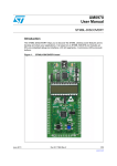
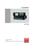
Single-phase energy meter solution based on STPM10 and STM8L152C6
with dual interface EEPROM
Doc ID 022953 Rev 1
1/35
www.st.com
Contents
UM1529
Contents
1
Features . . . . . . . . . . . . . . . . . . . . . . . . . . . . . . . . . . . . . . . . . . . . . . . . . . . 7
2
Overview . . . . . . . . . . . . . . . . . . . . . . . . . . . . . . . . . . . . . . . . . . . . . . . . . . 8
3
2.1
Safety rules . . . . . . . . . . . . . . . . . . . . . . . . . . . . . . . . . . . . . . . . . . . . . . . . 8
2.2
Recommended readings . . . . . . . . . . . . . . . . . . . . . . . . . . . . . . . . . . . . . . 8
2.3
Getting technical support . . . . . . . . . . . . . . . . . . . . . . . . . . . . . . . . . . . . . . 8
Getting started . . . . . . . . . . . . . . . . . . . . . . . . . . . . . . . . . . . . . . . . . . . . . . 9
3.1
Package . . . . . . . . . . . . . . . . . . . . . . . . . . . . . . . . . . . . . . . . . . . . . . . . . . . 9
3.2
Hardware installation . . . . . . . . . . . . . . . . . . . . . . . . . . . . . . . . . . . . . . . . . 9
3.3
Software installation . . . . . . . . . . . . . . . . . . . . . . . . . . . . . . . . . . . . . . . . . . 9
3.3.1
System requirements for demonstration GUI . . . . . . . . . . . . . . . . . . . . . 10
4
Hardware layout . . . . . . . . . . . . . . . . . . . . . . . . . . . . . . . . . . . . . . . . . . . . 11
5
Hardware details . . . . . . . . . . . . . . . . . . . . . . . . . . . . . . . . . . . . . . . . . . . 12
5.1
Metering IC U1 . . . . . . . . . . . . . . . . . . . . . . . . . . . . . . . . . . . . . . . . . . . . . 12
5.1.1
5.2
5.3
5.4
Microcontroller U2 . . . . . . . . . . . . . . . . . . . . . . . . . . . . . . . . . . . . . . . . . . 12
5.2.1
LED D10 . . . . . . . . . . . . . . . . . . . . . . . . . . . . . . . . . . . . . . . . . . . . . . . . 12
5.2.2
Switch SW1, SW2 . . . . . . . . . . . . . . . . . . . . . . . . . . . . . . . . . . . . . . . . . 12
5.2.3
Jumper J2 . . . . . . . . . . . . . . . . . . . . . . . . . . . . . . . . . . . . . . . . . . . . . . . 12
5.2.4
Clocking Y2 . . . . . . . . . . . . . . . . . . . . . . . . . . . . . . . . . . . . . . . . . . . . . . 12
Power supply section . . . . . . . . . . . . . . . . . . . . . . . . . . . . . . . . . . . . . . . . 13
5.3.1
Programmable voltage reference U5 . . . . . . . . . . . . . . . . . . . . . . . . . . . 13
5.3.2
Current sensor CT1 . . . . . . . . . . . . . . . . . . . . . . . . . . . . . . . . . . . . . . . . 13
5.3.3
Shunt RS1 . . . . . . . . . . . . . . . . . . . . . . . . . . . . . . . . . . . . . . . . . . . . . . . 13
Neutral missing power supply section . . . . . . . . . . . . . . . . . . . . . . . . . . . 13
5.4.1
2/35
Clocking Y1 . . . . . . . . . . . . . . . . . . . . . . . . . . . . . . . . . . . . . . . . . . . . . . 12
Current sensor CT2 . . . . . . . . . . . . . . . . . . . . . . . . . . . . . . . . . . . . . . . . 13
5.5
EEPROM U3 section . . . . . . . . . . . . . . . . . . . . . . . . . . . . . . . . . . . . . . . . 13
5.6
LCD section . . . . . . . . . . . . . . . . . . . . . . . . . . . . . . . . . . . . . . . . . . . . . . . 13
5.7
Battery management section . . . . . . . . . . . . . . . . . . . . . . . . . . . . . . . . . . 14
5.7.1
Coin cell BT1 . . . . . . . . . . . . . . . . . . . . . . . . . . . . . . . . . . . . . . . . . . . . . 14
5.7.2
Rechargeable battery BT2 . . . . . . . . . . . . . . . . . . . . . . . . . . . . . . . . . . . 14
Doc ID 022953 Rev 1
UM1529
Contents
5.8
6
5.7.3
Small signal Schottky diode D11, D12, D13, D14, D5 . . . . . . . . . . . . . . 14
5.7.4
Switch SW3 . . . . . . . . . . . . . . . . . . . . . . . . . . . . . . . . . . . . . . . . . . . . . . 14
IRDA section . . . . . . . . . . . . . . . . . . . . . . . . . . . . . . . . . . . . . . . . . . . . . . 14
5.8.1
IRDA transceiver U6 . . . . . . . . . . . . . . . . . . . . . . . . . . . . . . . . . . . . . . . 14
5.8.2
Jumper J6 . . . . . . . . . . . . . . . . . . . . . . . . . . . . . . . . . . . . . . . . . . . . . . . 14
5.9
Magnetic sensor U4 . . . . . . . . . . . . . . . . . . . . . . . . . . . . . . . . . . . . . . . . . 15
5.10
Connector section . . . . . . . . . . . . . . . . . . . . . . . . . . . . . . . . . . . . . . . . . . 15
Single-phase energy meter features . . . . . . . . . . . . . . . . . . . . . . . . . . . 16
6.1
Auto-calibration mode . . . . . . . . . . . . . . . . . . . . . . . . . . . . . . . . . . . . . . . 16
6.1.1
Steps for auto-calibration . . . . . . . . . . . . . . . . . . . . . . . . . . . . . . . . . . . . 16
6.2
EEPROM data log . . . . . . . . . . . . . . . . . . . . . . . . . . . . . . . . . . . . . . . . . . 17
6.3
Power management . . . . . . . . . . . . . . . . . . . . . . . . . . . . . . . . . . . . . . . . . 17
6.4
6.3.1
Meter run mode . . . . . . . . . . . . . . . . . . . . . . . . . . . . . . . . . . . . . . . . . . . 17
6.3.2
Meter low-power mode . . . . . . . . . . . . . . . . . . . . . . . . . . . . . . . . . . . . . 17
LCD display modes . . . . . . . . . . . . . . . . . . . . . . . . . . . . . . . . . . . . . . . . . 18
6.4.1
Meter run mode display . . . . . . . . . . . . . . . . . . . . . . . . . . . . . . . . . . . . . 18
6.4.2
Auto-scroll mode . . . . . . . . . . . . . . . . . . . . . . . . . . . . . . . . . . . . . . . . . . 18
6.4.3
Pushbutton mode . . . . . . . . . . . . . . . . . . . . . . . . . . . . . . . . . . . . . . . . . . 18
6.5
Meter low-power mode display . . . . . . . . . . . . . . . . . . . . . . . . . . . . . . . . . 19
6.6
Tamper detection . . . . . . . . . . . . . . . . . . . . . . . . . . . . . . . . . . . . . . . . . . . 19
6.7
6.8
6.6.1
Tamper types . . . . . . . . . . . . . . . . . . . . . . . . . . . . . . . . . . . . . . . . . . . . . 19
6.6.2
LCD symbol for tamper condition . . . . . . . . . . . . . . . . . . . . . . . . . . . . . . 19
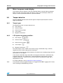
62056-21 IRDA protocol mode C . . . . . . . . . . . . . . . . . . . . . . . . . . . . . . . 20
6.7.1
IRDA modes . . . . . . . . . . . . . . . . . . . . . . . . . . . . . . . . . . . . . . . . . . . . . . 20
6.7.2
SerialIO GUI . . . . . . . . . . . . . . . . . . . . . . . . . . . . . . . . . . . . . . . . . . . . . 20
Pulse-out LED . . . . . . . . . . . . . . . . . . . . . . . . . . . . . . . . . . . . . . . . . . . . . 21
Appendix A EEPROM log data structure . . . . . . . . . . . . . . . . . . . . . . . . . . . . . . . 22
6.9
Size overview . . . . . . . . . . . . . . . . . . . . . . . . . . . . . . . . . . . . . . . . . . . . . . 23
6.10
Entry structure . . . . . . . . . . . . . . . . . . . . . . . . . . . . . . . . . . . . . . . . . . . . . 23
Appendix B Tamper definitions . . . . . . . . . . . . . . . . . . . . . . . . . . . . . . . . . . . . . . . 26
Appendix C Schematics . . . . . . . . . . . . . . . . . . . . . . . . . . . . . . . . . . . . . . . . . . . . . 27
C.1
Schematics . . . . . . . . . . . . . . . . . . . . . . . . . . . . . . . . . . . . . . . . . . . . . . . . 27
Doc ID 022953 Rev 1
3/35
Contents
UM1529
Appendix D Bill of material . . . . . . . . . . . . . . . . . . . . . . . . . . . . . . . . . . . . . . . . . . 29
Revision history . . . . . . . . . . . . . . . . . . . . . . . . . . . . . . . . . . . . . . . . . . . . . . . . . . . . 34
4/35
Doc ID 022953 Rev 1
UM1529
List of tables
List of tables
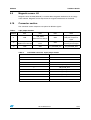
Table 1.
Table 2.
Table 3.
Table 4.
Table 5.
Table 6.
Table 7.
Table 8.
Table 9.
Table 10.
Table 11.
Table 12.
Table 13.
Table 14.
3-pin jumper header . . . . . . . . . . . . . . . . . . . . . . . . . . . . . . . . . . . . . . . . . . . . . . . . . . . . . . 12
Pin jumper headers. . . . . . . . . . . . . . . . . . . . . . . . . . . . . . . . . . . . . . . . . . . . . . . . . . . . . . . 14
4-pin jumper headers . . . . . . . . . . . . . . . . . . . . . . . . . . . . . . . . . . . . . . . . . . . . . . . . . . . . . 15
J7 STPM10 connector, 10-pin jumper header . . . . . . . . . . . . . . . . . . . . . . . . . . . . . . . . . . 15
EEPROM parameter size overview . . . . . . . . . . . . . . . . . . . . . . . . . . . . . . . . . . . . . . . . . . 23
Calibration data log . . . . . . . . . . . . . . . . . . . . . . . . . . . . . . . . . . . . . . . . . . . . . . . . . . . . . . . 23
Total cumulative energy log . . . . . . . . . . . . . . . . . . . . . . . . . . . . . . . . . . . . . . . . . . . . . . . . 24
Cumulative energy till last month . . . . . . . . . . . . . . . . . . . . . . . . . . . . . . . . . . . . . . . . . . . . 24
Monthly maximum demand. . . . . . . . . . . . . . . . . . . . . . . . . . . . . . . . . . . . . . . . . . . . . . . . . 24
Current monthly cumulative energy . . . . . . . . . . . . . . . . . . . . . . . . . . . . . . . . . . . . . . . . . . 24
Monthly average PF . . . . . . . . . . . . . . . . . . . . . . . . . . . . . . . . . . . . . . . . . . . . . . . . . . . . . . 24
Monthly tamper log . . . . . . . . . . . . . . . . . . . . . . . . . . . . . . . . . . . . . . . . . . . . . . . . . . . . . . . 25
BOM . . . . . . . . . . . . . . . . . . . . . . . . . . . . . . . . . . . . . . . . . . . . . . . . . . . . . . . . . . . . . . . . . . 29
Document revision history . . . . . . . . . . . . . . . . . . . . . . . . . . . . . . . . . . . . . . . . . . . . . . . . . 34
Doc ID 022953 Rev 1
5/35
List of figures
UM1529
List of figures
Figure 1.
Figure 2.
Figure 3.
Figure 4.
Figure 5.
Figure 6.
Figure 7.
Figure 8.
Figure 9.
6/35
Single-phase energy meter solution based on STPM10 and STM8L152C6 with dual interface
EEPROM . . . . . . . . . . . . . . . . . . . . . . . . . . . . . . . . . . . . . . . . . . . . . . . . . . . . . . . . . . . . . . . 1
Electricity meter connection diagram . . . . . . . . . . . . . . . . . . . . . . . . . . . . . . . . . . . . . . . . . . 9
Hardware layout: top view . . . . . . . . . . . . . . . . . . . . . . . . . . . . . . . . . . . . . . . . . . . . . . . . . 11
Hardware layout: bottom view . . . . . . . . . . . . . . . . . . . . . . . . . . . . . . . . . . . . . . . . . . . . . . 11
Auto-calibration mode connection diagram . . . . . . . . . . . . . . . . . . . . . . . . . . . . . . . . . . . . 16
SerialIO GUI hardware setup . . . . . . . . . . . . . . . . . . . . . . . . . . . . . . . . . . . . . . . . . . . . . . . 21
SerialIO GUI with protocol mode C settings . . . . . . . . . . . . . . . . . . . . . . . . . . . . . . . . . . . . 21
Schematics (1 of 2) . . . . . . . . . . . . . . . . . . . . . . . . . . . . . . . . . . . . . . . . . . . . . . . . . . . . . . . 27
Schematics (2 of 2) . . . . . . . . . . . . . . . . . . . . . . . . . . . . . . . . . . . . . . . . . . . . . . . . . . . . . . . 28
Doc ID 022953 Rev 1
UM1529
1
Features
Features
●
Low cost single-phase energy meter solution
●
Supports IEC 61036:1996 + A1: 2000, static meter for active energy classes 1 for
Ib=10 A
●
Less than 4 VA power consumption for voltage circuit at reference voltage
●
Less than 1 VA power consumption for current circuit at reference basic current
●
Multiple tamper detection: earth, neutral missing, reverse, case tamper, magnetic
tamper detection
●
Case tamper detection in power-down also
●
Detects, signals and continues to measure accurately under tamper condition
●
Rechargeable battery is available onboard for showing LCD parameters in case of
power-down mode
●
Active energy pulse output 1600 impulses/kWh
●
Software based auto-calibration without the need of reference meter, only reference
source is required
●
Microcontroller in-built RTC for date and time display
●
Microcontroller STM8L152C6T6 is responsible for all the data management, display
and power management
●
STPM10 metering IC with 1st order sigma-delta ADC for energy measurements
●
Single point and fast calibration of the STPM10 for class 1 meter
●
External EEPROM used to store calibration parameters, tampering information,
cumulative energy, MD and power factor (PF) data
●
Active power, current, voltage, power factor and line frequency measurements
●
Numeric display precision (except cumulative energy): 5+2 digits
●
Numeric display precision for cumulative energy: 5+1 digits
●
Energy EEPROM log precision: 0.01 kWh.
Doc ID 022953 Rev 1
7/35
Overview
UM1529
2
Overview
2.1
Safety rules
This board can be connected to mains voltage (240 V). In the case of improper use, wrong
installation or malfunction, there is a danger of serious personal injury and damage to
property. All operations such as transport, installation and commissioning, as well as
maintenance, should be carried out only by skilled technical personnel (regional accident
prevention rules must be observed).
Danger:
2.2
Due to the risk of death when using this prototype on mains
voltage (240 V), only skilled technical personnel who are
familiar with the installation, mounting, commissioning and
operation of power electronic systems and have the
qualifications needed to perform these functions, may use
this prototype.
Recommended readings
This documentation describes how to use the multi-tariff meter reference board.
Additional information can be found in the following documents:
2.3
●
STPM10 datasheet
●
STM8L152C6T6 datasheet
●
Component datasheets
●
IEC 62056-21 IrDA protocol mode C.
Getting technical support
For technical assistance, documentation, information and updates about products and
services, please refer to your local ST distributor/office.
8/35
Doc ID 022953 Rev 1
UM1529
Getting started
3
Getting started
3.1
Package
The demonstration kit package includes the following items:
●
Hardware content
–
●
–
●
3.2
STEVAL-IPE020V1 demonstration board
Software
SerialIO GUI for IRDA communication testing
Documentation:
–
User manual
–
Presentation
–
Schematic
–
BOM.
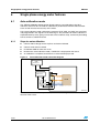
Hardware installation
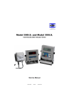
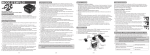
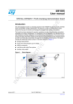
Connect the STEVAL-IPE020V1 demonstration board with the mains supply before load.
Please refer to Figure 2 for connection with mains power and load.
Auto-scrolling LCD display indicates successful power-up of the board.
Figure 2.
Electricity meter connection diagram
,#$
0HASE
.EUTRAL
0HASE
.EUTRAL
,OAD
,OAD
!-V
3.3
Software installation
The demonstration kit supports the SerialIO GUI for RS232 testing to check 62056-21 IRDA
protocol mode C implementation.
Doc ID 022953 Rev 1
9/35
Getting started
3.3.1
UM1529
System requirements for demonstration GUI
For demonstration board communication with the GUI, a recent version of Windows®,
Windows XP must be installed on the PC.
The SerialIO GUI does not require any driver installation.
The version of the Windows OS installed on PC can be determined by clicking on the
system icon in the control panel.
10/35
Doc ID 022953 Rev 1
UM1529
4
Hardware layout
Hardware layout
The demonstration kit hardware is designed in a sectional approach to offer multiple
functionalities to users.
Figure 3.
Hardware layout: top view
Figure 4.
Hardware layout: bottom view
Doc ID 022953 Rev 1
11/35
Hardware details
UM1529
5
Hardware details
5.1
Metering IC U1
The programmable single-phase energy metering IC STPM10BTR (package: TSSOP20) is
interfaced to the microcontroller using a three-wire SPI interface. Active energy, apparent
energy, instantaneous voltage, instantaneous current values are obtained from the STPM10
metering IC. For calibration of the STPM10, auto-calibration is implemented.
5.1.1
Clocking Y1
A 4.194 MHz crystal is used as clock generator input for the metering IC.
For more details about auto-calibration, please refer to Section 6.1: Auto-calibration mode.
5.2
Microcontroller U2
The microcontroller STM8L152C6T6 (package: LQFP48, 32 K Flash, 2 KB RAM, 48-pin) is
responsible for all the data management and power management tasks. MCU consumes
much lower power and has in-built RTC for date and time management.
5.2.1
LED D10
LED D10 is the pulse-out LED for cumulative energy. This is used for testing energy meter
energy calculation accuracy.
5.2.2
Switch SW1, SW2
Switch SW1 is the reset switch for the microcontroller.
Switch SW2 is the case tamper switch. This is used to detect case tampering of the energy
meter solution. For more details, refer to Section 6.4: LCD display modes.
5.2.3
Jumper J2
Table 1.
5.2.4
3-pin jumper header
Jumper
Close: 1-2
Close: 2-3
Default
J2
Microcontroller pin PA1
is connected to reset
switch SW1.
Microcontroller pin PA1
is connected to LED
D10.
Close: 2-3
Clocking Y2
A 32.768 kHz crystal is used as clock input for LSE (low speed external) for the
microcontroller RTC block. The microcontroller core is clocked by HSI (high speed internal)
clock.
12/35
Doc ID 022953 Rev 1
UM1529
5.3
Hardware details
Power supply section
Capacitive power supply is used to build 3.6 V for the metering IC and microcontroller
section.
5.3.1
Programmable voltage reference U5
U5 TL431AI (package TO-92) is used to regulate the 3.6 V supply.
5.3.2
Current sensor CT1
CT1 E4626-X002 (2500 turns, series resistance: 41.7 Ω) is the sensor for primary current
channel.
5.3.3
Shunt RS1
RS1 300 µΩ is the sensor for the secondary current channel.
5.4
Neutral missing power supply section
The neutral missing power supply section is operational in the case of neutral missing
tamper. In the case of neutral missing tamper condition, neutral is disconnected from the
energy meter. Hence, there is no voltage input and therefore no output would be generated
by the main capacitive power supply. However, in the case of load present, there would be a
valid input signal on the current channel so energy would be consumed. Since the voltage
on the neutral channel is zero, so is the power (P = V x I). In order to take account of energy
consumed in this case, the neutral missing power supply section provides voltage supply to
the STPM10 metering IC. A zero crossing signal of 50 Hz is provided to the VIP pin of the
STPM10, so it now calculates the energy consumption at a nominal voltage level of 230 V.
5.4.1
Current sensor CT2
CT2 is used to develop the power supply for the board using a diode full-wave rectifier circuit
in neutral missing condition.
5.5
EEPROM U3 section
Dual interface EEPROM M24LR64-RMN6T/2 (package: SO8, 64 Kbit) is interfaced to the
microcontroller using the I2C bus. This is a dual interface EEPROM and we can
communicate with this device using I2C communication (wired) as well as RF interface
(wireless) using an RF reader. Cumulative energy, MD, average PF and tamper information
for seven consecutive months are logged as months in EEPROM. For more details about
EEPROM data logging, refer to Section 6.2: EEPROM data log.
5.6
LCD section
LCD J3 is the connector for external 18* 4 LCD glass.
LCD glass OPT6089A (operating voltage 3 V, duty 1/4, Bias 1/3) offers various energy meter
specific symbols. LCD glass is driven by the microcontroller internal LCD driver.
Doc ID 022953 Rev 1
13/35
Hardware details
5.7
UM1529
Battery management section
Two batteries are used in the circuit.
5.7.1
Coin cell BT1
BT1 CR2032 (3 V, 225 mAh) is the microcontroller power source in halt mode to keep RTC
running.
5.7.2
Rechargeable battery BT2
BT2 VL2330 (3 V, 50 mAh) for pushbutton and IRDA operation when mains power is OFF.
5.7.3
●
The rechargeable battery acts as power source for the microcontroller section when the
pushbutton is pressed during mains power-off.
●
It is charged based on trickle charging mode during mains power-on.
Small signal Schottky diode D11, D12, D13, D14, D5
Diodes (D11, D12, D13, D14, D5) BAT30KFILM (SOD - 523) based circuit is used to select
power source for the microcontroller.
5.7.4
Switch SW3
Switch SW3 is the pushbutton switch. SW3 is used to control LCD display modes.
When mains power is ON, on pressing the pushbutton, the LCD display is executed as per
the pushbutton run mode.
When mains power is OFF, on pressing the pushbutton, the LCD display is executed as per
the pushbutton low-power mode.
5.8
IRDA section
5.8.1
IRDA transceiver U6
IRDA transceiver TFDU6300 is used for IRDA communication.
5.8.2
Jumper J6
Using jumper J6, IRDA transmit and receive pins allow the testing of the IRDA section using
the SerialIO GUI.
For more details, refer to Section 6.7.2: SerialIO GUI.
Table 2.
14/35
Pin jumper headers
Jumper
Pin1
Pin2
J6
PC3_IRDA_Tx
IRDA transmit pin
PC2_IRDA_Rx IRDA receive pin
Doc ID 022953 Rev 1
UM1529
5.9
Hardware details
Magnetic sensor U4
Magnetic sensor AH180 (SC59-3L) is used to detect magnetic interference in an energy
meter solution. Magnetic sensor outputs low on magnetic interference on the board.
5.10
Connector section
The connector section comprises test points for different signals.
Table 3.
4-pin jumper headers
Jumper
Pin1
Pin2
Pin3
Pin4
J1
VDD
PA0_SWIM
SWIM interface data pin
GND
PA1_NRST_PULSE_LED
LED pulse output/reset
signal
J5
PA0_SWIM
SWIM interface data pin
PE6
GPIO
GND
PE7_STPM_ZCR
metering IC ZCR signal
J4
GND
VDD
PC1_EEPROM_SCL
PC0_EEPROM_SDA
Table 4.
J7 STPM10 connector, 10-pin jumper header
Pin number
Details
1
VOTP
2
SBS
3
GND
4
PB7_STPM_SDA
5
PB6_STPM_SCS
6
PB5_STPM_SCL
7
PD6_STPM_LED
8
PA3_STPM_SYN
9
SBS
10
VDD
Doc ID 022953 Rev 1
15/35
Single-phase energy meter features
UM1529
6
Single-phase energy meter features
6.1
Auto-calibration mode
The STEVAL-IPE020V1 demonstration board supports auto-calibration using ideal
reference source for 10 A and 240 V. Calibration is performed to minimize measurement
errors and to increase the accuracy of the meter.
Using auto-calibration mode, calibration parameters (CHV, CHS, and CHP) are calculated
and programmed in the registers of the metering IC. The procedure for meter calibration is
explained below by firstly giving an overview of the hardware setup, and then by describing
how to connect a calibration board.
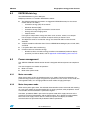
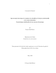
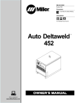
6.1.1
Steps for auto-calibration
●
Connect 240 V voltage source to phase and neutral of board
●
Connect 10 A source to board
●
Pushbutton SW3 for more than 4 sec
●
Board enters auto-calibration mode; “CALIB ON” is displayed on the board
●
As calibration is complete, board returns to auto-scroll display mode.
Figure 5.
Auto-calibration mode connection diagram
6
!#3OURCE
0
.
!3OURCE
3(5.4
340#4
!-V
For more details of calibration parameters, refer to the metering IC datasheet which can be
found on www.st.com.
16/35
Doc ID 022953 Rev 1
UM1529
6.2
Single-phase energy meter features
EEPROM data log
Total EEPROM data log size: 920 bytes.
Multiple parameters are stored in EEPROM as below:
●
The following metering parameters are logged in EEPROM memory for the current
month and last six months.
–
Cumulative energy (CE) till last month
–
Maximum demand (MD)
–
Cumulative energy (CE) consumed in current month
–
Average PF and averaging count
–
Tamper entries
Four types of tamper data storage are done: earth, reverse, neutral, case tamper.
For each type of tamper, the number of tamper entries per month is four.
●
Two duplicate entries of cumulative energy are stored with CRC-8 value for error
detection
●
10 bytes stored for calibration data @ start of EEPROM including 3 bytes of CHV, CHP,
and CHS
●
Last power-down date and time log
●
Overflow count for cumulative energy
–
6.3
Number of times cumulative energy overflows from 99999.9 (maximum display
precision), for further details, refer to Appendix A: EEPROM log data structure.
Power management
The STEVAL-IPE020V1 demonstration board is designed with board power consumption 4
VA.
The board supports two modes of operation:
6.3.1
●
Meter run mode
●
Meter lower power mode.
Meter run mode
When mains power is ON, the board operates in run mode. The board components are
powered using capacitive supply using the main power line as the source. In this mode, the
rechargeable battery is in charging mode based on trickle charging technique.
6.3.2
Meter low-power mode
When mains power goes down, the onboard microcontroller enters halt mode and metering
IC is off. In this mode, the microcontroller RTC is running and low, other peripherals are off.
In halt mode, the microcontroller is powered using BT1.
Therefore, pushbutton SW3 is pressed in low-power mode; BT2 supply connects to the
supply input of the microcontroller and the IRDA section. So, in button pressed condition,
BT2 is the main supply source. Now, the meter low-power LCD display and IRDA
communication are operational till pushbutton SW3 is operational.
Doc ID 022953 Rev 1
17/35
Single-phase energy meter features
6.4
UM1529
LCD display modes
The STEVAL-IPE020V1 demonstration board offers different parameters to the user.
The metering parameters display is configured in a specific manner based on the power
mode of the meter.
6.4.1
●
Meter run mode LCD display
●
Meter low-power LCD display.
Meter run mode display
During main power-on condition, all the critical parameters with details of last month logs for
metering parameters are available on the display.
Parameter display is classified in the manner below for mains ON condition:
6.4.2
●
Auto-scroll mode
●
Pushbutton display mode.
Auto-scroll mode
In auto-scroll mode, the following parameters are displayed on the LCD display one by one.
●
Cumulative active energy (kWh)
●
Max. demand (kW) of last month
●
Average PF of last consumption month.
Note:
Auto-scroll mode interval (8sec) is configurable in “autoscroll_display.h” in firmware.
6.4.3
Pushbutton mode
In pushbutton mode, the following parameters are displayed on the LCD on pressing
pushbutton SW3. Each button push displays the next pushbutton parameter.
If the pushbutton is in a pressed condition for 4sec, the board enters auto-calibration mode.
For more details on auto-calibration, refer to Section 6.1: Auto-calibration mode.
In pushbutton mode, the following parameters are displayed on the LCD.
●
All LCD segments ON
●
Date and time
●
Max. demand since last reset
●
Cumulative energy for last six months
●
Max. demand for last six months
●
Instantaneous PF
●
Instantaneous voltage
●
Instantaneous current
●
Instantaneous load in Watt.
When the pushbutton SW3 is released, the LCD display returns to auto-scroll mode after
pushbutton mode interval (10sec).
Note:
18/35
Pushbutton mode interval (8sec) is configurable in “pushbutton_display.h” in firmware.
Doc ID 022953 Rev 1
UM1529
6.5
Single-phase energy meter features
Meter low-power mode display
In low-power mode, the display is OFF till pushbutton SW3 is pressed. When pushbutton
SW3 is pressed in low-power mode, the display is ON in auto-scroll display mode. The
display is active till pushbutton SW3 is in pressed condition.
6.6
Tamper detection
STEVAL-IPE020V1 demonstration board supports multiple tamper detection and their
logging in EEPROM.
6.6.1
Tamper types
The following five types of tamper detection are:
6.6.2
●
Earth tamper
●
Reverse tamper
●
Neutral missing tamper
●
Case tamper
●
Magnetic interference.
LCD symbol for tamper condition
●
Earth tamper:
●
Reverse tamper:
●
Neutral missing tamper:
●
Case tamper:
●
Magnetic interference:
The three tampers (earth, reverse and neutral missing) are detected using a software
algorithm based on meter readings from metering IC.
In the case of neutral missing tamper detection, the board starts recording energy when the
load current is 2 A or higher.
Case tamper is detected using switch SW2 and magnetic interference is detected using
magnetic sensor U4. The symbol 'BP' is shared for displaying case tamper as well as
magnetic interference. It means that if any of the tampers are detected, symbol 'BP' is
displayed on the LCD.
For tamper definitions, refer to Appendix B: Tamper definitions.
Note:
In the present solution, magnetic tamper is not logged in EEPROM. Logging can be easily
done modifying the EEPROM log structure.
Doc ID 022953 Rev 1
19/35
Single-phase energy meter features
6.7
UM1529
62056-21 IRDA protocol mode C
The STEVAL-IPE020V1 demonstration board supports 62056-21 IRDA protocol mode C.
IRDA is used as a communication channel for reading meter data. In such systems, a
handheld unit (HHU) or a unit with equivalent functions is connected to a tariff device
(energy meter). The protocol offers five alternative protocol modes, A, B, C, D and E. This
solution covers mode C use. In mode C, data exchange is bi-directional and is always
initiated by the HHU with the transmission of a request message. In this mode, the HHU acts
as a master and the tariff device acts as a slave. These protocol modes permit meter
reading, manufacturer specific operation and programming mode. It is designed to be highly
suitable for electricity metering environments, particularly with regards to electrical isolation
and data security.
6.7.1
IRDA modes
●
Data readout mode
In data readout mode, the tariff device responds with all the data logged in EEPROM as per
EEPROM data structure (refer to Appendix A: EEPROM log data structure). Each data block
consists of a sequence of data lines separated by CR carriage return and LF linefeed.
●
Manufacturer specific mode
In manufacturer specific mode, RTC date and time setting is done.
●
Programming mode
In programming mode, as per the protocol, data read and write can be done at different
locations of EEPROM.
6.7.2
SerialIO GUI
The SerialIO GUI can be used as the test GUI for 62056-21 IRDA protocol mode C
implementation. Here, the protocol is tested using serial communication. For this testing, a
daughterboard with an RS232 converter is required to map the PC serial data signals to 3.4
V data signals of the board.
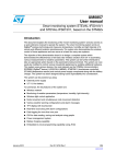
Steps for serial communication based protocol testing
20/35
●
Disconnect R41, R42 from board.
●
Comment “#defines IRDA_MODE_ENABLE” in “emter_irda.h”.
●
Connect the RS232 daughterboard as shown in Figure 6
●
Write data in the SerialIO GUI data box and send.
Doc ID 022953 Rev 1
UM1529
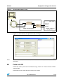
Figure 6.
Single-phase energy meter features
SerialIO GUI hardware setup
0#
4X
34
6##6
4X
*UMPER*
2X
2X
/PTO #OUPLER
4X0#
2X0#
3ERIAL#OMMUNICATION
34%6!, )0%6
%NERGY-ETER
!-V
Figure 7.
SerialIO GUI with protocol mode C settings
Note:
For more details about IRDA mode C, refer to the 62056-21 IRDA protocol mode C
document.
6.8
Pulse-out LED
LED D10 is used as pulse-out for cumulative energy. It works on a meter constant of 1600
impulses/kWh.
LED output can be used to test the accuracy of the meter.
Doc ID 022953 Rev 1
21/35
EEPROM log data structure
Appendix A
UM1529
EEPROM log data structure
All the below parameters are stored in EEPROM
●
Calibration data (10 bytes)
(3 bytes of CHV, CHP, CHS, then 7 times 0x00)
●
Total cumulative energy
(at two locations - to keep duplicate entries)
●
Total cumulative till last month
(month-wise for last six months and current month)
●
Maximum demand
(month-wise for last six months and current month)
●
Cumulative energy
(month-wise for last six months and current month)
●
Average PF and averaging count
(month-wise for last six months and current month)
●
Tamper information - earth, reverse, neutral missing, case tamper
(month-wise for last six months and current month and four entries per month with
count for tamper and date and time details)
●
Count of cumulative energy overflow
Count of cumulative energy overflow
●
Date and time of last power down
Total size required: 920 bytes.
Data storage structure in EEPROM as follows
●
Calibration data (CHV, CHP, CHS)
●
CE main entry with CRC
●
N month: CE till last month: MD: CE current month: average PF: tamper
●
N-1 month: CE till last month: MD: CE current month: average PF: tamper
●
N-2 month: CE till last month: MD: CE current month: average PF: tamper
●
N-3 month: CE till last month: MD: CE current month: average PF: tamper
●
N-4 month: CE till last month: MD: CE current month: average PF: tamper
●
N-5 month: CE till last month: MD: CE current month: average PF: tamper
●
N-6 month: CE till last month: MD: CE current month: average PF: tamper
●
CE duplicate copy with CRC
●
Count for cumulative energy overflow
●
Power-down date and time.
Where N is the current month
22/35
●
All parameters are logged for a total of 7 months including the current month and the
last 6 months
●
In current month log, data is updated at day end and on power-down
●
Total cumulative energy log is updated half-hourly
●
Month serial order is updated at 24:00 of last date of each calendar month.
Doc ID 022953 Rev 1
UM1529
6.9
EEPROM log data structure
Size overview
Table 5.
EEPROM parameter size overview
Parameter
Size (in bytes)
Calibration data
10 (3 bytes (CHV, CHP, CHS +7 dummy bytes for
future use))
Total cumulative energy duplicate entry 1
7 (4 bytes + 2 bytes + 1 byte (CRC))
Cumulative energy till last month
42 (7*6): without CRC
Maximum demand log
63 (7*(3+3+3))
Monthly cumulative energy
42 (7*6)
Average PF log
42 (7*4+7*2)
Earth tamper log
175 (7*((4*(3+3)) +1))
Reverse log
175 (7*((4*(3+3)) +1))
Neutral missing log
175 (7*((4*(3+3)) +1))
Case tamper log
175 (7*((4*(3+3)) +1))
Total cumulative energy duplicate entry 2
7 (4 bytes + 2 bytes + 1 byte (CRC))
Count for CE overflow
1 byte
Power down entry
6 bytes
Note:
EEPROM data structuring is done in a modular way to support future updates. Reconfigure
parameters in header file “emeter_datamgmt.h” to modify log structure entry count.
6.10
Entry structure
●
Calibration data log
CHV, CHP, CHS are calibration parameters for current and voltage channel for metering IC.
Table 6.
Calibration data log
Calibration data
(CHV, CHP, CHS, 7 times 0x00)
Start address
Size
0x00
10
For more details on calibration parameters, refer to the metering IC datasheet on
www.st.com.
●
Total cumulative energy log
Two duplicate entries are stored. One at the start of EEPROM and another at the end of
EEPROM.
This is done to make sure that, if EEPROM is corrupted at one point, another entry with
correct CRC is considered as valid value.
Doc ID 022953 Rev 1
23/35
EEPROM log data structure
Table 7.
UM1529
Total cumulative energy log
7 bytes (4 bytes: kWh, 2byte: impulse count & 1byte: CRC)
Total cumulative energy entry
●
Cumulative energy till last month
Cumulative energy till last month states energy consumed till the last calendar month reset.
Table 8.
Cumulative energy till last month
6 bytes (4 bytes: kWh & 2byte: impulse count)
Cumulative energy entry till last month
●
Monthly maximum demand
Table 9.
●
Monthly maximum demand
3 bytes (1 byte: integer value & 2byte: impulse count)
3 bytes
3 bytes
MD Value
Date
Time
Current monthly cumulative energy
Current monthly cumulative energy states energy consumed in that particular current month
till the last calendar month reset.
Table 10.
Current monthly cumulative energy
6 bytes (4 bytes: kWh & 2byte: impulse count)
Current cumulative energy entry
●
Monthly average PF
PF average value is sum of PF readings and PF averaging count is number of PF readings.
Table 11.
24/35
Monthly average PF
4 bytes
2 bytes
PF average value
PF averaging value
Doc ID 022953 Rev 1
UM1529
EEPROM log data structure
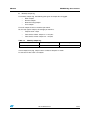
●
Monthly tamper log
For monthly tamper log, the following four types of tamper data is logged.
–
Earth tamper
–
Reverse tamper
–
Neutral missing tamper
–
Case tamper
For each tamper, there are 4 entries per month.
So, for each type of tamper, the storage per month is:
–
Tamper count: 1 byte
–
Four entries of date: 3 bytes x 4 : 12 bytes
–
Four entries of time: 3 bytes x 4 : 12 bytes
Table 12.
Monthly tamper log
1 byte
3 bytes
3 bytes
Tamper count
Date
Time
In one tamper entry log, tamper count: number of tampers in month
D: date and T: time each is of 3 bytes.
Doc ID 022953 Rev 1
25/35
Tamper definitions
Appendix B
●
If an attempt is made to open the meter body, the meter logs the date/time of
meter opening tamper
Magnetic tamper
–
26/35
When neutral is disconnected, the board is not powered. During this condition
(single wire conditions), power supply is generated by a CT for powering up the
board.
Case tamper
–
●
Reversal of phase and neutral at mains
Neutral missing tamper
–
●
Using earth in place of neutral (load current is passed partially or fully through
earth)
Reverse connection
–
●
Tamper definitions
Earth tamper
–
●
UM1529
When a magnet comes near to the board, it pulls magnetic sensor output IO low.
Doc ID 022953 Rev 1
Doc ID 022953 Rev 1
&21
3&B,5'$B7;
3&B,5'$B5;
5
N
5
(
,5'$B5['
,5'$B7['
&
X)
9''
'
%$7.),/0
9''
5
&
&
Q) X)
3(
9''
&
Q)
*1'
,5'$B7['
,5'$B5['
5
(
,5'$02'8/(
3$B%$7B(;7B/&'B386+
%$7.),/0
'
&
Q)
9''
5
5
6:
/&'B386+
'
%$7.),/0
7)'8
8
$12'(
&$7+2'(
7['
5['
6'
9&&
9/2*,&
*1'
%7
9B&5)1
%$77(5<6(&7,21
&
Q)
3'
3'
3'
3'
3)
3%
3%
3%
3%
3%
3%
3%
X)
&
3&B/6(B287
3'B+=B3:0
3'B+=B3:0
3'B670B/('
3'B/&'B6(*
3'B/&'B6(*
3)B06
3%B670B6'$
3%B670B6&6
3%B670B6&/
3%B/&'B6(*
3%B/&'B6(*
3%B/&'B6(*
3%B/&'B6(*
3&B/6(B,1
5
N
287387
$+B6&/
*1'
9''
8
-
&21
-
$170/5$B&21
9''
.OTE$O.OT-OUNT*
3)B06
&
S)
3$B670B6<1
3%B6730B6&/
6730B9,3
9''
3&B((3520B6&/ 3&B((3520B6'$ 5
N
&
S)
<
.+]
3(B3:5B'1
3$B6:,0
3(
0$*1(7,&6(1625
7(6732,17
73
9''
3$B6:,0
*1'
3$B1567B38/6(B/('
9''
&211(&7256(&7,21
3'B670B/(' 6:,0&211
-
3%B/&'B6(*
3'B/&'B6(*
3'B/&'B6(*
3'B/&'B&20
3'B/&'B6(*
3(B/&'B6(*
3(B/&'B6(*
3(B/&'B6(*
3(B/&'B6(*
3(B/&'B6(*
3(B/&'B6(*
%7
9B9/9&1
5
N
'
%$7.),/0
&
X)
'
%$7.),/0
9&&B6730
&
Q)
9/&'
3%
3'
3'
3'
3'
3(
3(
3(
3(
3(
3(
9/&'
X)
670/&7
/4)3
3$ 15673$ 3$ 3$ 3$ 3$ 3$ 3$ 95()
9''
9''$
95()
3&
3&
9'',2
966,2
3&
3&
3&
3&
3&
3&
3(
3(
&
Q)
9''$
&
3&B((3520B6'$
3&B((3520B6&/
9''
*1'
3&B,5'$B5;
3&B,5'$B7;
3&B&$6(B7$03(5
3&B/6(B,1
3&B/6(B287
3&B/&'B6(*
3(
3(B3:5B'1
X+B%(('
3$B6:,0
3$B1567B38/6(B/('
3$B%$7B(;7B/&'B386+
3$B670B6<1
3$B/&'B&20
3$B/&'B&20
3$B/&'B&20
3$B/&'B6(*
*1'
9''
9''$
8
3%B670B6&6
5
5
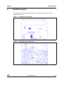
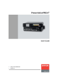
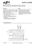
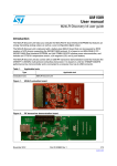
Schematics (1 of 2)
/
3&B&$6(B7$03(5
&
Q)
5
3%B6730B6&6
3$B6730B6<1
3%B670B6&/
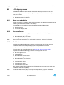
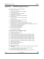
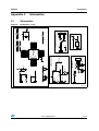
Figure 8.
-
6:
/('
'
6:
5(6(7
5
N
3%B670B6'$
3'B670B/('
Schematics
&$6(7$03(5
5
N
3$B1567B38/6(B/('
5
3%B6730B6'$
C.1
&
X)
9''
5
5
3'B6730B/('
Appendix C
&
Q)
9''
&21
-
9''
0,&52&21752//(56(&7,21
UM1529
Schematics
Schematics
!-V
27/35
28/35
Doc ID 022953 Rev 1
3$B/&'B6(*
3(B/&'B6(*
3(B/&'B6(*
3(B/&'B6(*
3(B/&'B6(*
3(B/&'B6(*
3(B/&'B6(*
3'B/&'B6(*
3'B/&'B6(*
3'B/&'B6(*
3%B/&'B6(*
3%B/&'B6(*
3%B/&'B6(*
3%B/&'B6(*
3%B/&'B6(*
3'B/&'B6(*
3'B/&'B6(*
3&B/&'B6(*
3$B/&'B&20
3$B/&'B&20
3$B/&'B&20
3'B/&'B&20
'
1
1
'
5
5
5
(
(
(
6&/
:&
9&&
966 6'$
0&50173B62
8
&
X)9
(:
5
3&B((3520B6'$
3&B((3520B6&/
((35206(&7,21
X)9
&
5
N
5
N
9&&B6730
9''
&
Q)
1(875$/0,66,1*32:(56833/<6(&7,21
1(875$/0,66,1*
&7
3+$6(
3
&
Q)
1(875$/
1
(:
5
9$&
X+
/
5
(
029
9
-OUNTONLYONE9OR2
.OTE$ONOTMOUNT#
6KXQW%.:05X2KP
%/$&.
5('
56
&7
7(;
&
X)
5
(
&
X)
5
(:
9$&
&
Q)
&
Q)
&
Q)9
5
5
.
5
.
5
5
.
5
.
9&&B6730
&
X)
5
0
5
N
5
NB
&
Q)9
5
NB
5
0
9&&B6730
$*1'
9273
3%B6730B6&6
/('
,,3
,,1
9,3
9,1
6<1
&/.,1
&/.287
6&/
6'$
'
1
5
(
'
1
&
X)9
'
1
6730B9,3
&
Q)
$*1'
&
X)9
'
1
3$B6730B6<1
6730B&/.,1
3%B6730B6&/
3%B6730B6'$
3'B6730B/('
&
X)
5
N
5
8
7/B72
5
(
5
N
32:(56833/<6(&7,21
4
%&%
5
NB
6730%75B76623
,,1
,,3
9''$
9273
9&&
966
9'''
6&6
023
021
8
(
5
&
S)
-
&
S)
5
N
/
X+
73
&
Q)
(;76833/<
$*1'
*1'
6%6
6%6
3%B6730B6'$
3%B6730B6&/
3$B6730B6<1
9''
9&&B6730
&
X)9
5
3(B3:5B'1
5
N
&21$3
.+]
5
0
<
9273
*1'
3%B6730B6&6
3'B6730B/('
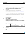
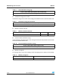
Figure 9.
/&'B*/$66&211
-
/&'6(&7,21
67306(&7,21
Schematics
UM1529
Schematics (2 of 2)
!-V
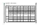
Table 13.
Category
Doc ID 022953 Rev 1
ST devices
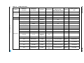
Bill of material
BOM
Reference
designator
Component
description
Package
Manufacturer
Manufacturer’s
ordering code /
orderable part number
U1
STPM metering
engine
TSSOP20
ST
STPM10BTR
STPM10BTR
U2
STM8L
microcontroller
LQFP48
ST
STM8L152C6T6
STM8L152C6T6
U3
EEPROM 32 Kb
SO8
ST
M24C32-RMN6TP
M24C32-RMN6TP
U5
Voltage reference
TO92
ST
TL431AIZ
TL431AIZ
D5,D11,D12,D13,D14
Small signal diode
SOD-523
ST
BAT30KFILM
BAT30KFILM
D6,D7
Diode Schottky
40 V 1 A
DO-41
ST
1N5819
1N5819
Dual interface
EEPROM to be
mounted on
daughterboard and
connected to J4
M24LR64-R dual
interface EEPROM
SO-8
ST
M24LR64-RMN6T/2
M24LR64-RMN6T/2
Y1
4194.304 kHz
oscillator
2-pin (3.5mm)
ECS Inc
ECS-42-12-4X
Digi-Key
X1046-ND
Y2
32.768 kHz
oscillator
2-pin
(Cylindrical)
Abracon
Corporation
AB26T-32.768KHZ
Digi-Key
535-9032-ND
J1
Swim connector
(SMT, 4-pin, 1.27
mm pitch)
SMD
ERNI
ERNI
ERNI
284697
J2
3-pin connector
3-pin (2.54 mm)
Crystal and
oscillator
Any
Supplier
Supplier ordering
code
29/35
Bill of material
Connectors
and jumpers
UM1529
Appendix D
Category
Connectors
and jumpers
LEDs
Doc ID 022953 Rev 1
Capacitors
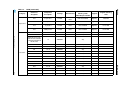
BOM (continued)
Manufacturer’s
ordering code /
orderable part number
Reference
designator
Component
description
Package
J4,J5
4-pin connector
4-pin (2.54 mm)
Any
J6
2-pin connector
2-pin (2.54 mm)
Any
J7
10 way, 2x5-pin
2x5 (2.54 mm)
Any
D10
LED
Leaded (3 mm)
HLMP-K150
C1,C3,C4,C20,C23,C
27
1 µF
SMD0805
Any
C2,C29
1 nF
SMD0805
Any
C5,C14,C15,C17,C21,
C22,C24,C28,C31
100 nF
SMD0805
Any
C6,C8
15 pF
SMD0805
Any
C7,C10
10 nF
SMD0805
Any
C9,C11
12 pF
SMD0805
Any
C12
4.7 µF
SMD1206
Any
C16,C30
4.7 µF
Tantulum SMD
EIA 321618/Size A
C13
22 nF
SMD0805
C18
200 nF/630 V
Leaded
Vishay/BC
Components
C19
220 µF/16 V
Leaded
C25
1 nF/500 V
C26
100 µF/50 V
Supplier
Supplier ordering
code
Digi-Key
516-1311-ND
BFC2 383 20204
Digi-Key
BC1857-ND
Panasonic ECG
EEU-FC1C221
Digi-Key
P11199-ND
Leaded
Vishay/BC
Components
D102K25Y5PL63L6R
Digi-Key
1457PH-ND
Leaded
Panasonic ECG
ECE-A1HN101U
Digi-Key
P1284-ND
Manufacturer
Bill of material
30/35
Table 13.
Any
Any
UM1529
Category
BOM (continued)
Component
description
Package
Manufacturer
Manufacturer’s
ordering code /
orderable part number
Supplier
Supplier ordering
code
C32
6.8 µF/16 V
Leaded
Panasonic ECG
ECE-A1CKG6R8
Digi-Key
P909-ND
C33
470 µF/35 V
Leaded
Nichicon
UVR1V471MPD
Digi-Key
493-1084-ND
C34
47 µF/50 V
Leaded
Panasonic ECG
ECA-1HM470
Digi-Key
P5181-ND
C35
1000 µF/16 V
Leaded
Panasonic ECG
ECA-1CM102
Digi-Key
P5142-ND
R1,R13,R32,R36,R37
10 kΩ
SMD0805
Any
R2
1 MΩ
SMD0805
Any
R3,R8,R11,R17,R18,
R20,R21,R27,R33,R3
4,R35,R42,R43,R44,R
46,R47,R49
0
SMD0805
Any
R4,R10,R14,R19
1 kΩ
SMD0805
Any
R5
6.8 Ω
SMD0805
Any
R6
5.1 Ω
SMD0805
Any
R7
42.2 kΩ
SMD0805
Any
R9,R15
2 MΩ
SMD0805
Any
R12
100 Ω
SMD0805
Any
R16
2.2 kΩ
SMD0805
Any
R22,R41
100 kΩ
SMD0805
Any
R23,R24,R25
261 kΩ
SMD1206
Any
R26
475 Ω
SMD0805
Any
R28
82, 2 W
Leaded
Digi-Key
82W-2-ND
R29
15 kΩ
SMD0805
Any
R30
22 kΩ
SMD0805
Any
Capacitors
Doc ID 022953 Rev 1
Resistors
Yageo
RSF200JB-82R
31/35
Bill of material
Reference
designator
UM1529
Table 13.
Category
BOM (continued)
Manufacturer’s
ordering code /
orderable part number
Reference
designator
Component
description
Package
R31
47 Ω
SMD0805
Any
R38
5.1 Ω
SMD0805
Any
R39
10E, 2 W
Leaded
R40
8 kΩ
SMD0805
Any
R45
27E, 5 W
R48
12 kΩ
SMD0805
Any
L1
220 µH
SMD
Panasonic ECG
L2, L3
1 µH
SMD
D1,D2,D3,D4,
DIODE GPP 1A
1000 V DO41
U6
Supplier
Supplier ordering
code
Digi-Key
PPC150W-2CT-ND
ELJ-FB221JF
Digi-Key
PCD1469CT-ND
Panasonic ECG
ELJ-FC1R0JF
Digi-Key
PCD1228CT-ND
Leaded
Fairchild
Semiconductor
1N4007
Digi-Key
1N4007FSCT-ND
Infrared transceiver
module (SIR, 115.2
kbit/s)
SMD-8-pin
Vishay
Electronics
TFDU6300-TR3
Digi-Key
751-1082-1-ND
U4
Micropower
omnipolar Halleffect sensor
switch
SC-59-3L
Diodes Inc.
AH180_SC59-3L
Digi-Key
AH180-WGDICT-ND
SW1
RESET switch for
micro
Leaded
Tyco
Electronics
1555986
Farnell
FSM10JH
SW2
CASE TAMPER
switch
Leaded
Tyco
Electronics
1555986
Farnell
FSM10JH
Resistors
Manufacturer
Vishay/BC
Components
PR02000201500JR500
Bill of material
32/35
Table 13.
Doc ID 022953 Rev 1
Inductors
Diode
Misc.
components
UM1529
Category
Misc.
components
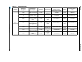
BOM (continued)
Doc ID 022953 Rev 1
Reference
designator
Component
description
Package
Manufacturer
Manufacturer’s
ordering code /
orderable part number
Supplier
Supplier ordering
code
SW3
LCD_PUSH switch
Leaded
Tyco
Electronics
1555986
Farnell
FSM10JH
J3
LCD glass 18x4
22-pin
connector
OPT6089A
PIE
Electronics
PIE Electronics
MOV1
SUR absorber 10
mm 750 V 2500 A
ZNR
Leaded
Panasonic ECG
ERZ-V10D751
Digikey
P7260-ND
RS1
Current sensing
resistors
5WATT.0003OHM
1%
Leaded
ISABELLENH
UTTE
BKW-M-R0003-5.0
Electric
center
BKW-M-R0003-5.0
CT1
Current transformer
Leaded
VACUUMSCH
MELZE (VAC)
T60404-E4626-X002
Vacuumsc
hmelze
T60404-E4626-X002
BT1
BATTERY LITHIUM
COIN 3 V W/TABS
Leaded
Panasonic BSG
CR-2032/F4N
Digi-Key
P245-ND
BT2
BATT LITH COIN 3
V 23 MM 50 MA
VERT
Leaded
Panasonic BSG
VL-2330/VCN
Digi-Key
P086-ND
UM1529
Table 13.
Bill of material
33/35
Revision history
UM1529
Revision history
Table 14.
34/35
Document revision history
Date
Revision
18-Sep-2012
1
Changes
Initial release.
Doc ID 022953 Rev 1
UM1529
Please Read Carefully:
Information in this document is provided solely in connection with ST products. STMicroelectronics NV and its subsidiaries (“ST”) reserve the
right to make changes, corrections, modifications or improvements, to this document, and the products and services described herein at any
time, without notice.
All ST products are sold pursuant to ST’s terms and conditions of sale.
Purchasers are solely responsible for the choice, selection and use of the ST products and services described herein, and ST assumes no
liability whatsoever relating to the choice, selection or use of the ST products and services described herein.
No license, express or implied, by estoppel or otherwise, to any intellectual property rights is granted under this document. If any part of this
document refers to any third party products or services it shall not be deemed a license grant by ST for the use of such third party products
or services, or any intellectual property contained therein or considered as a warranty covering the use in any manner whatsoever of such
third party products or services or any intellectual property contained therein.
UNLESS OTHERWISE SET FORTH IN ST’S TERMS AND CONDITIONS OF SALE ST DISCLAIMS ANY EXPRESS OR IMPLIED
WARRANTY WITH RESPECT TO THE USE AND/OR SALE OF ST PRODUCTS INCLUDING WITHOUT LIMITATION IMPLIED
WARRANTIES OF MERCHANTABILITY, FITNESS FOR A PARTICULAR PURPOSE (AND THEIR EQUIVALENTS UNDER THE LAWS
OF ANY JURISDICTION), OR INFRINGEMENT OF ANY PATENT, COPYRIGHT OR OTHER INTELLECTUAL PROPERTY RIGHT.
UNLESS EXPRESSLY APPROVED IN WRITING BY TWO AUTHORIZED ST REPRESENTATIVES, ST PRODUCTS ARE NOT
RECOMMENDED, AUTHORIZED OR WARRANTED FOR USE IN MILITARY, AIR CRAFT, SPACE, LIFE SAVING, OR LIFE SUSTAINING
APPLICATIONS, NOR IN PRODUCTS OR SYSTEMS WHERE FAILURE OR MALFUNCTION MAY RESULT IN PERSONAL INJURY,
DEATH, OR SEVERE PROPERTY OR ENVIRONMENTAL DAMAGE. ST PRODUCTS WHICH ARE NOT SPECIFIED AS "AUTOMOTIVE
GRADE" MAY ONLY BE USED IN AUTOMOTIVE APPLICATIONS AT USER’S OWN RISK.
Resale of ST products with provisions different from the statements and/or technical features set forth in this document shall immediately void
any warranty granted by ST for the ST product or service described herein and shall not create or extend in any manner whatsoever, any
liability of ST.
ST and the ST logo are trademarks or registered trademarks of ST in various countries.
Information in this document supersedes and replaces all information previously supplied.
The ST logo is a registered trademark of STMicroelectronics. All other names are the property of their respective owners.
© 2012 STMicroelectronics - All rights reserved
STMicroelectronics group of companies
Australia - Belgium - Brazil - Canada - China - Czech Republic - Finland - France - Germany - Hong Kong - India - Israel - Italy - Japan Malaysia - Malta - Morocco - Philippines - Singapore - Spain - Sweden - Switzerland - United Kingdom - United States of America
www.st.com
Doc ID 022953 Rev 1
35/35