1
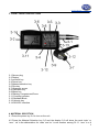
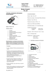
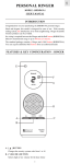
www.pce-industrial-needs.com
Tursdale Technical Services Ltd
Unit N12B
Tursdale Business Park
Co. Durham
DH6 5PG
United Kingdom
Phone: +44 ( 0 ) 191 377 3398
Fax: +44 ( 0 ) 191 377 3357
[email protected]
http://www.industrial-needs.com/
Manual Thickness meters
PCE-TG 50
[email protected]
Manual Thickness meters ........................................................................................................ 1
PCE-TG 50 .............................................................................................................................. 1
1. FEATURES ......................................................................................................................... 3
2. SPECIFICATIONS ............................................................................................................... 3
3. FRONT PANEL DESCRIPTIONS ........................................................................................ 4
4. MATERIAL SELECTION ..................................................................................................... 4
5. CALIBRATION ..................................................................................................................... 6
6. MEASURING PROCEDURE ............................................................................................... 6
7. MEASURING BY VELOCITY SETTING .............................................................................. 6
8. BATTERY REPLACEMENT ................................................................................................ 7
This thickness meter is small in size, light in weight, easy to carry. Although complex and
advanced, it is convenient to use and operate. Its ruggedness will allow many year of use if
proper operating techniques are followed. Please read the following instructions carefully and
always keep this manual within easy reach.
2
[email protected]
1. FEATURES
• Used the exclusive micro-computer LSI circuit and crystal time base to offer high
accuracy measurement.
•
With high power emission and broad band of receiving sensitivity, the gauge can match
probe of different frequencies.That makes it easy to measure the rough surface, even
cast iron. It is widely used in almost all kinds of industries.
•
Applicable to measure the thickness of many materials, e.g. Steel, Cast iron, Aluminium,
Red copper, Brass, Zinc, Quartz glass, Polyethylene, PVC, Gray cast iron, Nodular cast
iron.
•
Automatic power off to conserve power.
•
Can communicate with PCE computer for statistics an printing by the opcitonal cable
and the software for RS-232C interface.
2. SPECIFICATIONS
Display: 4 digits, 10 mm LCD
Range: 1.0 -200mm (45# steel)
Resolution: 0.1mm/0.00 linch
Accuracy: + (0.5%n+0.1)
Sound velocity: 500-9000 m/s
Power supply 4x1.5v AAA(UM-4) battery
Operating condition: Temp. 0-50ºC
Humidity<80%
Size: 120x62x30mm(4.7 x 2.4 x 1.2 inch)
Weight: about 164g (not including batteries)
Accessory:
Carrying case…..……1 pc
Operation manual…...1 pc
Ultrasonic sensor……1 pc
Optional accessories:
Cable & software for RS-232C
3
[email protected]
3. FRONT PANEL DESCRIPTIONS
3-1 Sensor plug
3-2 Display
3-3 mm/inch key
3-4 Power key
3-5 Material selection key
3-6 Plus key
3-7 Ultrasonic sensor
3-8 Calibration key
3-9 Minus key
3-10 Battery Compartment/Cover
3-11 Coupling indicator
3-12 Standard Block
3-13 Velocity key
3-14 RS-232C interface
4. MATERIAL SELECTION
4.1 Press the power key 3-4 to turn on the unit.
4.2 Press the Material Selection key 3-5 and the display 3-2 will show the code ‘cdxx’ or
‘xxxx’. ‘cd’ is the abbreviation for ‘code’ and ‘xx’ is one number among 01-11. ‘xxxx’ is a 4
4
[email protected]
digit number which is the sound velocity of material defined by the user. The ‘cdxx’ material
relationship is as follow.
No. CODE Material
1
cd01
Steel
2
cd02
Cast iron
3
cd03
Aluminium
4
cd04
Rep copper
5
cd05
Brass
6
cd06
Zinc
7
cd07
Quartz glass
8
cd08
Polyethylene
9
cd09
PVC
10
cd10
Gray cast iron
11
cd11
Nodular cast iron
12
cd12
Sound velocity
4.3 Press the Plus key 3-6 or Minus key 3-9 to select the material code to measure and press
the Material Selection key to confirm. The display will show 0. If you select a material code
but do no confirm the selection, the code will automatically change to 0 after several
seconds. In such case, the meter will still reserve the material code before exiting.
4.4 A 4 digit number will be shown on the Display if pressing the plus key 3-6 when
displaying ‘cd11’ or pressing the Minus key 3-9 when displaying ‘cd01’. The 4 digit number is
last sound velocity to define by the user. By selecting this velocity, you could measure the
thickness of the same material as last.
4.5 It is unnecessary to select the material code once the material code is confirmed(
automatically stored to the memory of the meter) unless the material to measure is diferrent
from that before.
4.6 To browse the material code selected, if only press the Select key 3-5 again or wait till
the code automatically change to 0 after several seconds or the meter will automatically
return to measurement state if measuring.
5
[email protected]
5. CALIBRATION
5.1 Drop a little oil on the 5 mm standard block 3-12.
5.2 Press the Calibration key 3-8, the ‘CAL’ be shown on the Display. ‘CAL’ is the short for
calibration.
5.3 Press the sensor 3-7 on the standard block. The coupling symbol ((●)) is on if coupling
well. 5mm ( or 0.197 inch) and ‘CAL’ will be shown on the Display in turn. When steady,
Press CAL key 3-8 to confirm and then the unit return to the state of measurement.
5.4 The calibration result will be auto-saved to the unit once confirmation. It is unnecessary to
calibrate often unless you suspect the accuracy measurement.
6. MEASURING PROCEDURE
6.1 Press the power key 3-4 to turn on the unit.
6.2 Press the mm/inch key 3-3 to select the right measurement unit.
6.3 Press the Sensor 3-7 onto the material surface to measure on the premise that the
material code selected is right. Be sure that coupling is well and the symbol ((●)) is on. The
reading on display is the measurement value.
6.4 The reading is held till a new measurement value is coming. The last value is held on the
display till the power is off.
6.5 2 modes to turn off the power.
Manual off at any time by pressing the power key or Auto power off after about 1 minutes
from last key operation.
7. MEASURING BY VELOCITY SETTING
7.1 Press the VEL key 3-13 and the display shows the velocity set last time.
7.2 How to measure its thickness by the velocity known?
The velocity can be changed by pressing the plus key or minus key to the value of known
velocity the increment is 10m/s every time. When pressing the plus or minus key. And the
increment is 100/ms if depressing the key formore than about 4 seconds.
7.3 Drop a little oil into the material to measure and press the Sensor 3-7 onto the surface.
The reading on the display is the thickness. The reading on the display is the thickness if
coupling well. So if we have known the velocity of a certain material, it is easy to measure the
thickness by 7.2.
6
[email protected]
7.4 How to measure the thickness by a sample of known thickness?
Just get a sample of known thickness. Then repeat 7.2 and 7.3 till the measurement value is
totally same as the known thickness. In such a case, the set value is the velocity of the
material to measure, by which you can measure any unknown thickness of same material.
7.5 To browse the velocity, if only press the VEL key 3-13. To quit browsing, if only press the
VEL key 3-13 again or wait till the meter automatically show 0.
7.6 By use of velocity measurement, it is easy to measure the thickness of any hard
materials.
8. BATTERY REPLACEMENT
8.1 When the battery symbol appears on the display, it is time to replace the batteries.
8.2 Slide the Battery Cover away from the instrument and remove the batteries.
8.3 Install batteries paying careful attention to polarity.
In this direction will find a vision of the measurement technique:
http://www.industrial-needs.com/measuring-instruments.htm
NOTE: "This instrument doesn’t have ATEX protection, so it should not be used in potentially explosive
atmospheres (powder, flammable gases)."
7