1
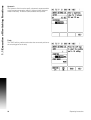
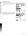
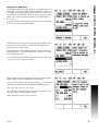
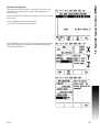
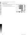
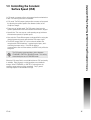
Operating Instructions IFB 48 English (en) 4/2013 1 Operating Instructions ..... 5 1 General Information ..... 6 Installation ..... 6 Connecting the IFB 48 to X101 ..... 6 1.1 Execution of Switching Functions ..... 7 Switching inputs ..... 7 Switching outputs ..... 7 1.2 Spindle Speed Control (RPM) ..... 11 Milling Systems ..... 11 Mill Spindle Installation setup ..... 12 Voltage / RPM Setup ..... 14 1.3 Controlling the Constant Surface Speed (CSS) ..... 17 Configuration of CSS ..... 18 CSS operating mode ..... 19 Activating the DAC output ..... 20 Connecting the IFB 48 to the inverter of the lathe ..... 21 1.4 Diagnostics ..... 22 General Information ..... 22 Switching I/O functions ..... 22 CSS, and Mill Spindle ..... 23 IFB 48 3 4 Operating Instructions General Information General Information Installation Refer to the IFB 48 Mounting Instructions document ID 1065244-xx for details. Connecting the IFB 48 to X101 For executing switching functions (milling), or controlling the constant surface speed CSS (turning) When the IFB 48 is connected to the DRO that support this feature, the functionality described above are available. The DRO automatically recognizes when the IFB 48 is connected and displays the CSS SETUP option or the SWITCHING OUTPUTS option in the INSTALLATION SETUP menu. These options can be used to configure all functions of the switching unit. 6 I Operating Instructions 1.1 Execution of Switching Functions 1.1 Execution of Switching Functions If you want to use both the IFB 48 and the KT 130 edge finder at the same time, or if you want to transmit measured values via the external switching output, the distribution cable with ID 532909-01 is required. Switching inputs The IFB 48 provides four inputs that are used to zero the actual value of the assigned axis. A low-to-high transition at the input causes the value for that axis to be set to zero. Switching outputs The switching outputs consist of integrated relays available for generic usage. The number of switching outputs available is dependent on the configuration options chosen. When the system is configured for a Mill, and the spindle speed control (RPM) is disabled, 8 switching outputs are available. If RPM is enabled, then only 6 switching outputs are available. See "Spindle Speed Control (RPM)" on page 11. When the system is configured for a Lathe, and the constant surface speed (CSS) is disabled, 8 switching outputs are available. If CSS is enabled, then only 5 switching outputs are available. See "Controlling the Constant Surface Speed (CSS)" on page 17. The switching outputs are activated depending on “position”. The relays can be configured to activate when a position display reaches a specific value, or within a specified range of zero. The ninth output relay indicates readiness. Select SWITCHING OUTPUTS from the INSTALLATION SETUP menu to open the SWITCHING OUTPUTS table in which the configuration of the outputs are stored. If you want to change the configuration of an output, select it with the arrow keys, and press ENTER to confirm your selection. This opens the OUTPUT SETTINGS form in which you define the switching conditions. To reset a relay, select the relay in the table and press the CLEAR RELAY soft key, followed by the YES soft key for confirmation. IFB 48 7 1.1 Execution of Switching Functions The AXIS field is used to assign an axis to the output. The CONDITION field is used to assign an axis to the output and to specify whether the axis position is an actual-value or distance-to-go position. You also specify the position display value at which the relay is activated, and the required condition. The POINT/RANGE field is used to define whether the conditions refers to a point on the axis or refers to a range about zero. If the condition is set to equal, the relay will activate momentarily even if the switching point is crossed over too quickly for the value to appear. Possible switching states of the relays. 8 I Operating Instructions 1.1 Execution of Switching Functions In PULSED mode, the relay is activated (ON or OFF) for a specific period of time. After the period has timed out, the relay is deactivated. The pulse time is 0.1 to 999 seconds. Relay Continuous mode shown: The time period begins whenever the switching condition transitions from FALSE to TRUE. If the switching conditions transitions to TRUE before the period has timed out, the timer will start over. Condition Pulsed mode shown: Relay Condition IFB 48 9 1.1 Execution of Switching Functions Hysteresis The Hysteresis field is used to specify a hysteresis range around the switching output target point, and axis. Hysteresis helps eliminate chatter in the relay. A value of 0 (zero) disables the Hysteresis. Teach The TEACH soft key can be used to select the current axis position as the switching point for the relay. 10 I Operating Instructions 1.2 Spindle Speed Control (RPM) 1.2 Spindle Speed Control (RPM) Milling Systems The Mill Spindle Speed Control is for milling systems only, and provides an open loop spindle speed control. The spindle speed control requires the IFB 48 box. The spindle speed control is only available for milling systems. If the DRO is configured for a turning system, then no Spindle Settings will be displayed. Define the last axis as a rotary encoder axis. Display Define the display as a speed display. IFB 48 11 1.2 Spindle Speed Control (RPM) Mill Spindle Installation setup The configuration parameters are found under Installation Setup. The Spindle Settings only appear in the list if the IFB 48 box is detected. Select Spindle Settings from the Installation Setup menu, and press the ENTER key. The spindle (RPM) status field allows the user to enable, or disable the spindle (RPM) functionality. If it is disabled, then no spindle (RPM) operations are available for usage. If the spindle (RPM) is enabled, then all of the following setup must be completed. Six (6) generic switching outputs will then be available. 12 I Operating Instructions 1.2 Spindle Speed Control (RPM) Voltage Offset / RPM Source The voltage offset field is used to adjust for any inherent offset in the DAC output. This value is added to the calculated DAC output. Use a voltmeter to measure the actual voltage at the DAC output. Press the INCREASE, or DECREASE soft key to adjust the offset until the output is 0 V. The offset range is limited to 0 - 50, (approximately 0 - 122 mV). Press ENTER to save the settings, and exit the form, or press the C key to exit without saving the changes. The RPM source allows the user to define whether the RPM source is from an actual rotary encoder, or calculated by the software as a replacement for a rotary encoder. User speed limits can be established to limit how fast, or slow the spindle may be run. These are run time limits, and must fit in within the actual hardware limits. Press ENTER to save the settings, and exit the form, or press the C key to exit without saving the changes. When in Setup mode, the status bar will display the current spindle speed in RPM’s shown in the S: field on the status bar. To set a specific spindle speed, the DAC output SOut uses this linear relationship to determine the corresponding output voltage VOut: VOut = 10 • (SOut - S0) / (S10 - S0) + VOffset Press ENTER to save the parameters and exit the input form. Press the C key to exit without saving the changes. These are the physical limits of the machine. IFB 48 13 1.2 Spindle Speed Control (RPM) Voltage / RPM Setup The voltage setup fields are used to establish the relationship between the DAC output signal (0 - 10 V), and the spindle speed for each gear. Enter min, and max voltage levels for each gear. Press ENTER to save the settings, and exit the form, or press the C key to exit without saving the changes. This screen allows the spindle to have min, and max RPM settings defined. This limits the spindle not to exceed the limits set at start up. The spindle speed can then be manually incremented above the “Run Time” limits. After selecting Spindle Settings from the Installation Setup menu, use the RIGHT or LEFT arrow hard keys to scroll to this menu. 14 I Operating Instructions 1.2 Spindle Speed Control (RPM) Operation / Job Execution The operation of the Mill Spindle is associated with the use of the selected tool from the tool table, and the spindle parameters for running the tool. Refer to the DRO User’s Manual for setting up, and using a tool from the tool table. Select the desired tool from the tool table. Press ENTER to open the tool setup form. Press the RPM calc key to specify a surface speed, and get a resultant RPM spindle speed that is automatically loaded into the tool table when exiting the RPM calc. IFB 48 15 1.2 Spindle Speed Control (RPM) A tool can be run from the tool table, or by pressing enter after defining the spindle parameters for a tool. Mill Spindle Feature Run With all tool, job, and installation setups entered, the Mill Spindle job can be run by toggling the Spindle ON/OFF soft key. Select the tool to be used, and the required gear. The spindle speed can be adjusted using the SPEED +/- soft keys. 16 I Operating Instructions 1.3 Controlling the Constant Surface Speed (CSS) 1.3 Controlling the Constant Surface Speed (CSS) In CSS mode, a constant surface cutting speed can be maintained on a lathe. The following functions are available: CSS mode: The DAC output signal provides constant surface speed by adjusting the spindle speed as the diameter (radius) of the workpiece changes. Direct entry of spindle speed: The DAC output signal sets the spindle speed based on the value entered via the numeric keypad. Speed limits: The user may set a safe operating range (minimum and maximum speeds) for spindle speed. Gear selection: Three different gears can be specified for varying the relation between the actual speed and the DAC output signal. The READY output (X103-12) is active when the readout has recognized the IFB 48 hardware, is monitoring the inputs, and is controlling the output relays. If the IFB 48 detects a communications error with the readout, the READY relay will be deenergized. The CSS setting screen provides a choice between STANDARD, LIMITED or DISABLED mode. This setting should always be set to STANDARD mode. When the CSS status field is set to disabled, then no CSS functionality is available. Eight (8) generic switching outputs are available for useage. When STANDARD, or LIMITED is selected, then the remaining setup options must be completed. Only 5 generic switching outputs will be available for usage. IFB 48 17 1.3 Controlling the Constant Surface Speed (CSS) Configuration of CSS To use the CSS functionality, the last axis must be defined as a rotary axis. Define the display as a speed display, and configure them accordingly. The spindle control configuration parameters are set up in the INSTALLATION SETUP menu. Select the CSS SETTINGS parameter to open the associated input form The CSS ON/OFF CONTROL field is used to specify whether the CSS mode is operated by soft key or by an external hardware signal. The current gear may be selected by local control (MANUAL via CSS / DIRECT RPM in the JOB SETUP menu) or remote control (EXTERNAL; via switches in the machine gear). This is defined in the CSS GEAR SELECT field. The VOLTAGE OFFSET function is used to adjust for any inherent offset in the DAC signal. Using a voltmeter, measure the actual voltage at the DAC output. Press INCREASE or DECREASE to adjust the offset until the output is 0 V. The offset range is limited from 0 to 100 (approximately 0 to 244mV). The VOLTAGE / RPM fields are used to establish the relationship between the DAC output signal (0 to 10 V) and the spindle speed. The minimum and maximum limits for each gear are entered. If the position display of the third axis is configured to be used for the spindle speed, the rpm in the SETTING field can be set to the current spindle speed by pressing the TEACH soft key. To set a specific spindle speed, the DAC output SOut uses this linear relationship to determine the corresponding output voltage VOut: VOut = 10 · (SOut - S0) / (S10 - S0) + VOffset Press ENTER to save the parameters and exit the input form. Press the C key to exit without saving the changes you made. 18 I Operating Instructions 1.3 Controlling the Constant Surface Speed (CSS) CSS operating mode The operating parameters are set in the CSS / DIRECT RPM form. Press the CSS SETUP soft key to open the form or select the parameter from the JOB SETUP menu. The SETTINGS field is used to select the mode of operation and the control settings. The spindle is controlled by selecting CSS or by entering the spindle speed directly. The values to be entered depend on the selected option. If CSS was selected to maintain a constant surface speed, the surface speed entered with the numeric keys is maintained. As the diameter of the part changes, the spindle speed will be adjusted. To set a specific spindle speed, select DIRECT / RPM and enter the value with the numeric keypad. If the position display of the third axis is configured to be used for the spindle speed, the rpm in the SETTING field can be set to the current spindle speed by pressing the TEACH soft key. Select OFF when spindle control is not needed. The GEAR SELECTION field is used to manually enter the operating gear with the numeric keypad. If the gear control parameter in INSTALLATION SETUP is set to EXTERNAL, the field will show the current gear selection based on the external inputs. The field can then not be selected and is skipped. The LIMITS field is used to establish the minimum and maximum limits of the controlled spindle speed. When operating in the CSS or DIRECT RPM modes, the DAC output will not be set to a speed above or below these limits. Press ENTER to save the parameters and exit the input form. Press the C key to exit without saving the changes you made. The “Spindle Speed” will default to the OFF position when ever the Readout power is cycled, and the run mode must be reselected to use. No settings are lost when power is cycled. The Max RPM field is discarded between runs in Limited mode only, requiring to teach a new max RPM each time. IFB 48 19 1.3 Controlling the Constant Surface Speed (CSS) Activating the DAC output After selecting the operating mode and entering its parameters, the DAC output must be enabled to begin controlling the spindle. The output to the spindle inverter drive is an open loop signal. The system does not monitor the actual spindle speed. The output signal is based solely on the inverter's speed input versus the input voltage profile. Depending on the operating mode selected, the RPM or CSS soft key is displayed on the fourth page of the soft key menu. If the current state indicated on the soft key is ON, the DAC output is active. Press the soft key to OFF to disable the spindle control. If CSS is active, the CSS icon appears next to the X-axis display. If the entered surface speed or rpm cannot be maintained because the speed is outside the range for the current gear or outside the limits from the CSS/RPM SETTINGS form, an arrow will appear after the CSS icon ( or ). The direction of the arrow indicates whether the speed is at the upper or lower limit. The soft key to enable CSS or RPM control will not appear if the operating mode is set to OFF. If the CSS control parameter under INSTALLATION SETUP is set to EXTERNAL, the CSS or RPM operation cannot be controlled by soft key. The soft key will show the current state, but pressing it will have no effect. The SPEED + and SPEED – soft keys are used to increase or decrease the current surface speed or spindle speed. The value is increased or decreased by 5% each time the soft key is pressed. 20 I Operating Instructions 1.3 Controlling the Constant Surface Speed (CSS) Connecting the IFB 48 to the inverter of the lathe IFB 48 Example of gear detection and switching to manual spindle speed control IFB 48 Example of switching to manual spindle speed control IFB 48 21 1.4 Diagnostics 1.4 Diagnostics General Information When the IFB 48 box is connected to the DRO, the DIAGNOSTICS menu under INSTALLATION SETUP provides further diagnostic possibilities. The information available varies depending on the configuration of the system, Switching I/O, CSS, or Mill Spindle functions. Switching I/O functions The SWITCHING I/O DIAGNOSTICS shows the status of the communication via the CAN bus and the state of the switching inputs and outputs to provide monitoring of the switching functions. The CAN STATUS field shows the state of the bus communication between the DRO and the IFB 48. The status information has the following meaning: Information Meaning NOT PRESENT No communication with hardware NOR Communication – normal operation CAL Communication – Hardware in calibration mode Wen Watchdog active Wds Watchdog inactive Wto Watchdog time-out Tx Data is transmitted to hardware Rx Data is received by hardware The SWITCHING I/O field shows the state of the inputs and the switch position of the relays. All currently active inputs (1 to 3) are shown in the ON field. All currently active relay outputs (1 to 9) are shown in the OFF field. The CALIBRATE soft key is used to re-synchronize the communication with the IFB 48. This, however, is only required if the module is not detected upon power on. 22 I Operating Instructions 1.4 Diagnostics CSS, and Mill Spindle CSS / MS DIAGNOSTICS shows the status of the communication via the CAN bus and the state of the DAC output to provide monitoring of the interfaces for operation with constant surface speed. The state of the switching inputs and outputs is also shown. The CAN STATUS field shows the state of the bus communication between the DRO, and the IFB 48. The status information has the following meaning: Information Meaning NOT PRESENT No communication with hardware NOR Communication – normal operation CAL Communication – Hardware in calibration mode Wen Watchdog active Wds Watchdog inactive Wto Watchdog time-out Tx Data is transmitted to hardware Rx Data is received by hardware The DAC OUTPUT field shows the current value of the transmitted voltage. The value is between 0 and 4095, which corresponds to a voltage of 0 to 10 V at X102-11. The corresponding CSS icon will be displayed if the spindle speed is at the upper or lower limit ( or ). The CSS INPUT/OUTPUT field shows the state of the switching inputs, and relay outputs. IFB 48 23 1.4 Diagnostics The MS INPUT/OUTPUT field shows the state relay outputs. The IN: field of the switching inputs is not used, and will be blank. The status information has the following meaning: Information about the inputs Meaning EXT External switch is active (X102-12) G1 Switch for gear 1 is active (X102-3,4) G2 Switch for gear 2 is active (X102-5,6) G3 Switch for gear 3 is active (X102-7,8) Information about the outputs Meaning POT Potentiometer relay is active (X102-10) DAC DAC output relay is active (X102-11) The CALIBRATE soft key is used to re-synchronize the communication with the IFB 48. This, however, is only required if the module was not detected at switch-on. 24 I Operating Instructions Index A Activating the DAC output ... 20 C Configuration of CSS ... 12, 18 Connecting the CSS I/O to the inverter of the lathe ... 21 Connecting the CSS I/O to X101 ... 6 Controlling the constant surface speed (CSS) ... 11, 17 CSS ... 23 CSS DIAGNOSTICS ... 23 CSS operating mode ... 19 D Diagnostics ... 22 E Execution of switching functions ... 7 G General Information ... 6, 7 M Mill Spindle Installation setup ... 12 Mill Spindle Job Run ... 16 O Operation / Job Execution ... 15 S Spindle Speed Control (RPM) ... 11 SWITCHING I/O DIAGNOSTICS ... 22 Switching I/O functions ... 22 Switching inputs ... 7 Switching outputs ... 7 V Voltage / RPM Setup ... 14 Voltage Offset / RPM Source ... 13 IFB 48 25 Index DISTRIBUTION CONTACTS Austria Corporate Head Quarters United Kingdom Switzerland China USA France RSF Elektronik Ges.m.b.H. A-5121 Tarsdorf +43 (0) 62 78 81 92-0 +43 (0) 62 78 81 92-79 e-mail: [email protected] internet: www.rsf.at Italy HEIDENHAIN (GB) Ltd. 200 London Road Burgess Hill West Sussex RH15 9RD +44 (0)1444 238550 +44 (0)1444 870024 e-mail: [email protected] Slovenia RSF Elektronik (Schweiz) AG Vieristrasse 14 CH-8603 Schwerzenbach +41 44 955 10 50 +41 44 955 10 51 e-mail: [email protected] internet: www.rsf.ch RSF Elektronik GmbH Tian Wei San Jie, Area A, Beijing Tianzhu Airport Industrial Zone Shunyi District 101312 Beijing P.R. China +86 (0) 10 80 42 02 88 +86 (0) 10 80 42 02 90 e-mail: [email protected] internet: www.rsf.cn Korea HEIDENHAIN FRANCE sarl 2 Avenue de la Christallerie 92310 Sèvres +33 1 41 14 30 00 +33 1 41 14 30 30 e-mail: [email protected] HEIDENHAIN ITALIANA S.r.l. Via Asiago, 14 20128 Milano (MI) +39 02 27075-1 +39 02 27075-210 e-mail: [email protected] RSF Elektronik prodaja, d.o.o. Jozeta Jame 14 SI-1210 Ljubljana +386 (0) 1 519 88 80 +386 (0) 1 519 88 80 e-mail: [email protected] HEIDENHAIN LTD. 201 Namsung Plaza, 9th Ace Techno Tower, 345-30, Gasan-Dong, Geumcheon-Gu, Seoul, Korea 153-782 +82 (0) 2 20 28 74 30 e-mail: [email protected] internet: www.rsf.co.kr HEIDENHAIN CORPORATION 333 East State Parkway Schaumburg, IL 60173-5337 +1 847 490 11 91 e-mail: [email protected] internet: www.rsf.net Technical adjustments in reserve! Ges.m.b.H. A-5121 Tarsdorf 1073173-20 · Ver00 · 4/2013 Linear Encoders Digital Readouts Precision Graduations Cable Systems +43 (0)6278 / 8192-0 Certified acc. to DIN EN ISO 9001 DIN EN ISO 14001 +43 (0)6278 / 8192-79 e-mail: [email protected] internet: www.rsf.at